US7621367B2 - Electric power steering apparatus - Google Patents
Electric power steering apparatus Download PDFInfo
- Publication number
- US7621367B2 US7621367B2 US11/434,222 US43422206A US7621367B2 US 7621367 B2 US7621367 B2 US 7621367B2 US 43422206 A US43422206 A US 43422206A US 7621367 B2 US7621367 B2 US 7621367B2
- Authority
- US
- United States
- Prior art keywords
- steering apparatus
- electric power
- connector
- set forth
- power steering
- Prior art date
- Legal status (The legal status is an assumption and is not a legal conclusion. Google has not performed a legal analysis and makes no representation as to the accuracy of the status listed.)
- Expired - Fee Related, expires
Links
Images


Classifications
-
- B—PERFORMING OPERATIONS; TRANSPORTING
- B62—LAND VEHICLES FOR TRAVELLING OTHERWISE THAN ON RAILS
- B62D—MOTOR VEHICLES; TRAILERS
- B62D5/00—Power-assisted or power-driven steering
- B62D5/04—Power-assisted or power-driven steering electrical, e.g. using an electric servo-motor connected to, or forming part of, the steering gear
- B62D5/0403—Power-assisted or power-driven steering electrical, e.g. using an electric servo-motor connected to, or forming part of, the steering gear characterised by constructional features, e.g. common housing for motor and gear box
- B62D5/0406—Power-assisted or power-driven steering electrical, e.g. using an electric servo-motor connected to, or forming part of, the steering gear characterised by constructional features, e.g. common housing for motor and gear box including housing for electronic control unit
-
- B—PERFORMING OPERATIONS; TRANSPORTING
- B62—LAND VEHICLES FOR TRAVELLING OTHERWISE THAN ON RAILS
- B62D—MOTOR VEHICLES; TRAILERS
- B62D5/00—Power-assisted or power-driven steering
- B62D5/04—Power-assisted or power-driven steering electrical, e.g. using an electric servo-motor connected to, or forming part of, the steering gear
- B62D5/0409—Electric motor acting on the steering column
-
- B—PERFORMING OPERATIONS; TRANSPORTING
- B62—LAND VEHICLES FOR TRAVELLING OTHERWISE THAN ON RAILS
- B62D—MOTOR VEHICLES; TRAILERS
- B62D5/00—Power-assisted or power-driven steering
- B62D5/04—Power-assisted or power-driven steering electrical, e.g. using an electric servo-motor connected to, or forming part of, the steering gear
- B62D5/0457—Power-assisted or power-driven steering electrical, e.g. using an electric servo-motor connected to, or forming part of, the steering gear characterised by control features of the drive means as such
- B62D5/046—Controlling the motor
- B62D5/0463—Controlling the motor calculating assisting torque from the motor based on driver input
-
- B—PERFORMING OPERATIONS; TRANSPORTING
- B60—VEHICLES IN GENERAL
- B60Y—INDEXING SCHEME RELATING TO ASPECTS CROSS-CUTTING VEHICLE TECHNOLOGY
- B60Y2400/00—Special features of vehicle units
- B60Y2400/30—Sensors
- B60Y2400/307—Torque sensors
-
- B—PERFORMING OPERATIONS; TRANSPORTING
- B60—VEHICLES IN GENERAL
- B60Y—INDEXING SCHEME RELATING TO ASPECTS CROSS-CUTTING VEHICLE TECHNOLOGY
- B60Y2410/00—Constructional features of vehicle sub-units
- B60Y2410/12—Production or manufacturing of vehicle parts
- B60Y2410/124—Welded parts
Definitions
- the present invention relates to an electric power steering apparatus equipped with an electric motor for outputting assist torque to the steering wheel of a vehicle, and a control unit for controlling the driving of the electric motor.
- This electric power steering apparatus includes a power board on which a bridge circuit is mounted for switching the current of the electric motor, a control board on which a microcomputer is mounted for generating a drive signal to control the bridge circuit, and a high current board on which a conductive plate forming a high current wiring pattern is insert molded and on which a capacitor is mounted for absorbing current ripples, wherein the power board, the high current board and the control board are stacked or laminated one over another in this order so as to form a three-layer structure.
- the control unit has a substrate comprising the three boards, i.e., the power board, the high current board and the control board, which are laminated one over another in this order to form the three-layer structure. Accordingly, the height of the control unit becomes large, and connecting members for connecting these boards with one another are required at the same time, resulting in increased connection or joint portions.
- the present invention is intended to obviate the problem as referred to above, and has its object to provide an electric power steering apparatus which can be reduced in size and cost, and improved in reliability of electrical connections by constructing a power board, a high current board and a control board by the use of a single substrate.
- an electric power steering apparatus including an electric motor for outputting assist torque to a steering wheel of a vehicle, and a control unit for controlling the driving of the electric motor.
- the control unit includes: a power main body that includes a bridge circuit composed of a plurality of semiconductor switching elements for switching a current supplied to the electric motor in accordance with torque assisting the steering wheel; a control main body that generates a drive signal to control the bridge circuit based on the steering torque of the steering wheel; a metal substrate that is composed of a plurality of insulating layers and a plurality of conductive layers having wiring patterns respectively formed thereon, the insulating layers and the conductive layers being alternately laminated one over another on a metal plate; and a heat sink with the metal substrate being fixedly attached thereto.
- the power main body and the control main body are arranged on the same surface of the metal substrate, and the power main body and the control main body are electrically connected to each other through the metal substrate.
- the power main body and the control main body are mounted on the single metal substrate, so the apparatus can be reduced in size and cost, and the reliability of electrical connections can be improved.
- FIG. 1 is a cross sectional view showing an electric power steering apparatus according to a first embodiment of the present invention.
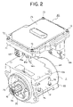
- FIG. 2 is an exploded perspective view showing the electric power steering apparatus in FIG. 1 .
- FIG. 3 is an exploded perspective view showing a control unit of the electric power steering apparatus in FIG. 1 .
- FIG. 4 is a partial cross sectional view showing a metal substrate of the electric power steering apparatus in FIG. 1 .
- FIG. 5 is a partial cross sectional view showing a modified form of the metal substrate of the electric power steering apparatus in FIG. 1 .
- FIG. 6 is a plan view showing a part of the metal substrate of the electric power steering apparatus in FIG. 1 .
- FIG. 7 is a partial cross sectional view of the control unit of FIG. 1 .
- FIG. 8 is another partial cross sectional view of the control unit of FIG. 1 .
- FIG. 9 is a cross sectional view showing an electric power steering apparatus according to a second embodiment of the present invention.
- FIG. 10 is an exploded perspective view showing a control unit of the electric power steering apparatus in FIG. 2 .
- FIG. 1 is a cross sectional view that shows an electric power steering apparatus according to a first embodiment of the present invention.
- FIG. 2 is an exploded perspective view that shows the electric power steering apparatus in FIG. 1
- FIG. 3 is an exploded perspective view that shows a control unit 20 in FIG. 2 .
- an electric motor 1 in the form of a three-phase brushless motor of this electric power steering apparatus is provided with an output shaft 2 , a rotor 4 with a permanent magnet 3 having eight magnetic poles fixedly attached to the output shaft 2 , a stator 5 arranged around the rotor 4 , and a rotational position sensor 6 arranged at an output side of the output shaft 2 for detecting the rotational position of the rotor 4 .
- the stator 5 has twelve salient poles 7 arranged in opposition to the outer periphery of the permanent magnet 3 , insulators 8 attached to these salient poles 7 , respectively, and armature windings 9 of three phases U, V and W wound around the insulators 8 , respectively.
- the armature windings 9 have their three end portions connected with three winding terminals 10 , respectively, extending in an axial direction at the output side of the output shaft 2 .
- the rotational position sensor 6 is composed of a resolver, and has a resolver rotor 6 a and a resolver stator 6 b .
- the outside diameter or contour of the resolver rotor 6 a is formed into a special curve so that the permeance of a diametral clearance or gap between the reservoir stator 6 b and the resolver rotor 6 a changes in a sinusoidal manner at a relative angle therebetween.
- An excitation coil and two sets of output coils are wound around the resolver stator 6 b , so that a change in the diametral gap between this the resolver rotor 6 a and the resolver stator 6 b can be detected and output from the output coils as two-phase output voltages that change in a sine curve and in a cosine curve, respectively.
- the electric motor 1 is fixedly attached to a reduction mechanism in the form of a reduction gear 11 .
- the reduction gear 11 includes a gear case 13 to which a housing 12 of the electric motor 1 is attached, a worm gear 14 that is arranged in the gear case 13 and for decelerating the rotation of the output shaft 2 , and a worm wheel 15 that is in meshing engagement with the worm gear 14 .
- the worm gear 14 is formed, at an end portion thereof near the electric motor 1 , with a spline.
- a coupling 16 with a spline formed on its inner side is press-fitted into an end portion of the output shaft 2 near the reduction gear 11 .
- the coupling 16 and the one end portion of the worm gear 14 are coupled with each other through their splines, so that torque can be transmitted from the electric motor 1 to the reduction gear 11 through the coupling 16 .
- the control unit 20 for controlling the driving of the electric motor 1 is fixedly secured to a bracket 12 a that is formed at an upper portion of the housing 12 of the electric motor 1 , as shown in the FIG. 2 .
- the control unit 20 includes a heat sink 21 that is in the shape of a box and is made of aluminum of high conductivity, a metal substrate 22 arranged in the heat sink 21 , a cover 23 made of aluminum that cooperates with the heat sink 21 to receive the metal substrate 22 , etc., in its interior, and a connector 44 .
- the heat sink 21 , the metal substrate 22 and the cover 23 are arranged in parallel to the axial direction of the electric motor 1 .
- FIG. 4 is a cross sectional view of the metal substrate 22 , and the metal substrate 22 is composed, for instance, of an AGSP (a registered trademark of Daiwa Co., Ltd.) substrate, with a wiring pattern 26 a being formed on a metal plate 24 made of aluminum of 2 mm thick as a copper pattern of 35 ⁇ m through a heat dissipation insulating layer 25 of 80 ⁇ m.
- a metal plate 24 made of aluminum of 2 mm thick as a copper pattern of 35 ⁇ m through a heat dissipation insulating layer 25 of 80 ⁇ m.
- four interlayer insulating layers 27 a , 27 b , 27 c , 27 d each of 60 ⁇ m thick
- four wiring patterns 26 b , 26 c , 26 d , 26 e made of copper of 35 ⁇ m thick are laminated, respectively, one over another in an alternate manner.
- the wiring patterns 26 a through 26 e in the form of conductive layers are formed in five layers, and the wiring patterns 26 a through 26 e are connected with one another by means of interlayer power circuit metal columns (bumps) 28 a and interlayer control circuit metal columns 28 b , respectively.
- the uppermost insulating layer 27 d is formed of a material whose modulus of elasticity is smaller than those of the other insulating layers 27 a through 27 c .
- the insulating layer 27 d with a small modulus of elasticity serves to reduce the stress generated at soldered portions in the form of brazed portions of parts in the use environment of a motor vehicle, for example due to a temperature change between ⁇ 40° C. and 125° C., thereby improving the reliability of bonding or connection of the soldered portions of the parts.
- the heat dissipation insulating layer 25 is made of a material which is larger in thermal conductivity than the insulating layers 27 a through 27 d.
- a power main body 20 a at the output side of the electric motor 1 , and control main body 20 b at the opposite side thereof, as shown in FIG. 3 .
- the power main body 20 a is comprised of high current parts such as semiconductor switching elements (e.g., FET) Q 1 through Q 6 that constitutes a three-phase bridge circuit for switching a motor current of the electric motor 1 , capacitors 30 that absorb ripples of the motor current, shunt resistors 31 that detect the current of the electric motor 1 , and so on. These high current parts are mounted on the wiring pattern 26 e through soldering.
- semiconductor switching elements e.g., FET
- Q 1 through Q 6 that constitutes a three-phase bridge circuit for switching a motor current of the electric motor 1
- capacitors 30 that absorb ripples of the motor current
- shunt resistors 31 that detect the current of the electric motor 1 , and so on.
- a thermal conductive sheet 29 having high conductivity and excellent flexibility is fitted between the upper surface of each capacitor 30 and the inner wall surface of the cover 23 .
- the interlayer insulating layers 27 a , 27 b , 27 c , 27 d are formed by thermally pressing a resin-coated copper foil (RCC)
- the power circuit metal column body between the adjacent layers of the wiring patterns 26 a through 26 e are formed of a plurality of divided power circuit metal columns 28 a .
- the power circuit metal columns 28 a each have a circular shape in cross section, so the flowability of a resin of the resin-coated copper foil can be improved, and hence internal defects or flaws of the metal substrate 22 can be reduced.
- the power circuit metal columns 28 a are each formed into a bump structure with a circular cross section, but a through hole structure may instead be employed which has a ring-shaped cross sectional configuration.
- a resin having high thermal conductivity may be filled into the hollow interior of a through hole.
- the control main body 20 b is composed of low current parts such as a microcomputer 32 , a drive circuit (not shown), a peripheral circuit element including a motor current detection circuit (not shown) and so on. These low current parts are mounted on the wiring pattern 26 e by soldering.
- the microcomputer 32 calculates an assist torque based on the motor current, which flows into the motor 1 through one end of each shunt resistor 31 and is detected by the motor current detection circuit (not shown), and a steering torque signal from a torque sensor (not shown), and calculates a current corresponding to the assist torque by feeding back the motor current and the rotational position of the rotor 4 detected by the rotational position sensor 6 .
- the microcomputer 32 outputs drive signals to control the semiconductor switching elements Q 1 through Q 6 of the bridge circuit.
- the microcomputer 32 includes, though not illustrated, a well-known self-diagnosis function in addition to an AD converter, a PWM timer circuit, etc., and always carries out self-diagnosis so as to determine whether the system operates normally, so that it can interrupt the motor current upon occurrence of abnormality.
- the power main body 20 a and the control main body 20 b are arranged on the single metal substrate 22 , and are electrically connected to one another by means of the wiring patterns 26 a through 26 e , the interlayer power circuit metal columns 28 a and the interlayer control circuit metal columns 28 b . Accordingly, signal transmission between the control main body 20 b and the power main body 20 a is carried out through the wiring patterns 26 a through 26 e , the power circuit metal columns 28 a and the control circuit metal columns 28 b formed in the metal substrate 22 .
- the power circuit metal columns 28 a In the power main body 20 a including the high current parts such as the semiconductor switching elements Q 1 through Q 6 , the capacitors 30 , the shunt resistors 31 and so on, it is necessary for the power circuit metal columns 28 a to pass heat and a large current in the vicinity of the high current parts, so it is desirable that the power circuit metal columns 28 a each have a cross-sectional area as large as possible.
- each of the power circuit metal columns 28 a has a cross-sectional area as small as possible. Therefore, the cross-sectional area of each of the power circuit metal columns 28 a is formed to be larger than the cross-sectional area of each of the control circuit metal columns 28 b . It is preferable that each of the power circuit metal columns 28 a have a circular shape with a diameter of 0.7 mm or more in cross section, and that each of the control circuit metal columns 28 b have a circular shape with a diameter of 0.4 mm or less in cross section.
- pad portions 26 ep are formed on the wiring pattern 26 e on the top layer, and a lower surface of each pad portion 26 ep and an upper surface of the second uppermost wiring pattern 26 d are connected to each other by means of a corresponding control circuit metal column 28 b .
- a convex portion 26 f is formed on an upper surface of each pad portion 26 ep , and a capacitor C is mounted on adjacent convex portions 26 f and connected at its opposite ends with the pad portions 26 ep by soldering.
- soldering of the capacitor C is made while being lifted from the associated pad portions 26 ep by the convex portions 26 f , so that solder layers are thus formed to be thick in their portions except for those portions which correspond to the convex portions 26 f.
- the parts as referred to above may be ones of non-lead type such as resistors, etc., other than the capacitor C.
- wire bonding pad portions 26 eb to which wires W made of aluminum and each having a diameter of 300 ⁇ m are wire bonded, are formed in the wiring pattern 26 e on the top layer of the metal substrate 22 , as shown in FIG. 4 .
- the wire bonding pad portions 26 eb each have a lower surface connected to an upper surface of the second uppermost wiring pattern 26 d by a wire metal column 28 c .
- wire metal columns 28 c on a line in the thickness direction of the metal substrate 22 , but a wire metal column 28 c should be arranged at least between the lower surface of each wire bonding pad portion 26 eb and the upper surface of the second uppermost wiring pattern 26 d.
- each wire W and each corresponding wire bonding pad portion 26 eb is made at a location excluding a portion that extends over the corresponding wire metal column 28 c and the interlayer insulating layer 27 d in the lower surface of the wire bonding pad portion 26 eb . That is, each wire W is wire bonded to a corresponding wire bonding pad portion 26 eb in a region thereof in which the interlayer insulating layer 27 d is formed on the lower surface of the wire bonding pad portion 26 eb.
- each wire W is wire bonded to a corresponding wire bonding pad portion 26 eb in a region thereof in which a corresponding wire metal column 28 c is formed on the lower surface of the wire bonding pad portion 26 eb.
- a metal column 28 c formed downward from a corresponding wire bonding pad portion 26 eb may have a cross-sectional area equal to that of each power circuit metal column 28 a.
- the metal substrate 22 has holes 22 c formed therethrough at six locations in the peripheral portion thereof, and the metal substrate 22 is fixedly secured to the heat sink 21 by means of screws 70 threaded into these holes 22 c .
- the metal substrate 22 is fixedly secured to the heat sink 21 by means of screws 70 threaded into these holes 22 c .
- the fixed metal columns 28 d are arranged in a circular manner in a circular manner, which are disposed between adjacent layers of the wiring patterns 26 a through 26 e on individual lines in the thickness direction of the metal substrate 22 .
- the fixed metal columns 28 d are arranged under a bearing surface of the head of each screw 70 , so that a force generated by tightening of the screw 70 is applied to the fixed metal columns 28 d.
- the screws 70 are easy to loose, but by tightening the metal substrate 22 to the heat sink 21 with the screws 70 through the fixed metal columns 28 d , the screws 70 become difficult to loose, so the metal substrate 22 can be made in intimate contact with the heat sink 21 .
- the heat generated by heat-generating parts on the metal substrate 22 is efficiently conducted to the housing 12 of the electric motor 1 via the heat sink 21 .
- each of the fixed metal columns 28 d is not of course limited to twelve, but may be any value appropriate for heat conduction. Also, each of the fixed metal columns 28 d may be of a cylindrical through hole structure, similar to the power circuit metal columns 28 a.
- the metal plate 24 is made of aluminum in this embodiment, an AlSiC material may be used in which silicon carbide particles are dispersed in an aluminum material.
- the AlSiC material is higher in cost than aluminum but has a rigidity greater than that, so the thickness of the metal plate 24 can be made thinner than that of an aluminum plate, but it is preferable to select the thickness in a range substantially between 1.4 mm and 1.6 mm.
- the AlSiC material is smaller in the coefficient of thermal expansion than aluminum, and hence the reliability of solder bonding or joint of the parts mounted on the metal substrate 22 by soldering can be improved.
- the AlSiC material is used for the metal plate 24 , it is preferable that an AlSiC material having a similar coefficient of thermal expansion be used for the heat sink 21 .
- conductive plates 41 , 42 are insert molded in an insulating resin, with the conductive plates 41 being exposed from the insulating resin at portions to be electrically connected, as shown in FIG. 3 .
- Motor terminals Mm being formed as one ends of the conductive plates 41 , respectively, are protruded from corresponding holes 21 a , which are opening portions formed in the heat sink 21 , so as to be inserted into the electric motor 1 for electrical connection with the winding terminals 10 .
- the conductive plates 41 have pad portions 41 a formed at the other ends thereof, respectively, in a manner exposed from the insulating resin for connection to the bridge circuit of the power main body 20 a of the metal substrate 22 through wires bonded thereto by wire bonding.
- the conductive plates 42 have pad portions 42 a in the form of power supply terminals formed at one ends thereof, respectively, in a manner exposed from the insulating resin, and the pad portions 42 a are connected to the power main body 20 a through wires bonded thereto by wire bonding.
- the sensor connector 43 is integrally formed with the frame 40 , and is fitted into a connector (not shown) from the rotational position sensor 6 .
- a sensor terminal Sm for sending a signal from the rotational position sensor 6 to the microcomputer 32 is insert molded into the insulating resin.
- the sensor terminal Sm has one end exposed from the insulating resin to form a pad portion Smp, and the exposed pad portion Smp is connected to the control main body 20 b through a wire bonded thereto by wire bonding.
- the connector 44 is composed of a power connector 45 a electrically connected to a battery (not shown) of the vehicle, a signal connector 45 b by which signals are input from and output to the vehicle side through external wiring, and a torque sensor connector 46 to which a signal from a torque sensor (not shown) is input.
- the power connector 45 a and the signal connector 45 b are integrated with each other to form a vehicle connector 45 , and the vehicle connector 45 and the torque sensor connector 46 are arranged in side by side.
- the connector 44 is composed of a connector housing 47 and a connector frame 48 received in the connector housing 47 , and is fixedly secured to the heat sink 21 at a side opposite to the metal substrate 22 . Further, the connector 44 is arranged at a side of the metal substrate 22 opposite to the heat sink 21 , and it also is arranged in the vicinity of a rear end of the electric motor 1 that is at a side opposite to an output side of the electric motor 1 .
- a housing of the power connector 45 a a housing of the signal connector 45 b , and a housing of the torque sensor connector 46 are integrally molded with an insulating resin.
- the vehicle connector 45 and the torque sensor connector 46 are integrally formed with the connector housing 47 and the connector frame 48 , respectively.
- coils 54 , 55 and capacitors 56 that serve to prevent electromagnetic noise generated upon the switching operation of the semiconductor switching elements Q 1 through Q 6 of the power main body 20 a from flowing out to the outside, and they are connected to the conductive plates 49 , 50 , 51 , respectively, of the connector frame 48 .
- the connector frame 48 is formed with coil receiving portions 48 a , 48 b , in which the coils 54 , 55 are received and held by being inserted thereinto in a orthogonal direction with respect to the terminals 49 a , 50 a , 52 a of the vehicle connector 45 and the terminal 53 a of the torque sensor connector 46 .
- FIG. 7 is a cross sectional view of essential portions of the connector frame 48 , in which the coil receiving portion 48 b is formed on its bottom with a protrusion-like detent 48 c and a guide 48 d for engagement with the coil 55 .
- the coil 55 is constructed by winding a conductor around a core 55 a which has a T-shaped cross section when cut along an axial direction thereof.
- a large-diameter portion 55 b of the coil 55 is guided by the guide 48 d , so that when it is inserted up to the bottom of the coil receiving portion 48 b , the detent 48 c in the form of an engagement portion is elastically engaged with the large-diameter portion 55 b , thereby fixedly attaching the coil 55 to the connector frame 48 .
- the terminals 54 a , 55 c of the coils 54 , 55 penetrate through holes 48 e formed in the bottoms of the coil receiving portions 48 a , 48 b to protrude from the connector frame 48 , so that they are welded and electrically connected to the conductive plates 49 , 50 , 51 exposed from the insulating resin.
- FIG. 8 is a cross sectional view of essential portions of the connector frame 48 , in which the connector frame 48 is formed with capacitor receiving portions 48 f that receive the capacitors 56 , respectively.
- the capacitors 56 are arranged and received in a line or row, as shown in FIG. 3 .
- the conductive plates 49 , 50 , 51 are partially exposed from the insulating resin at one end side of the capacitor receiving portions 48 f , and the thus exposed conductive plates 49 , 50 , 51 are connected to corresponding terminals of the capacitors 56 by TIG welding.
- the welded portions being arranged on a straight line, are continuously connected by TIG welding.
- the connector housing 47 is formed with guide portions 47 a that serve to guide opposite side portions 48 g of the connector frame 48 when the connector frame 48 is inserted into the connector housing 47 .
- the side portions 48 g of the connector frame 48 are fitted into the guide portions 47 a , and the terminals 49 a , 50 a , 52 a , 53 a of the connector 44 and the housing of the connector 44 are positioned in an appropriate manner.
- an adhesive resin 66 is filled in between a terminal inserted portion, which is formed on the connector housing 47 and into which the terminals 49 a , 50 a , 52 a , 53 a are inserted, and a terminal protruded portion, which is formed on the connector frame 48 and into which the terminals 49 a , 50 a , 52 a , 53 a protrude.
- the connector frame 48 has a concave portion 48 h formed in a portion thereof into which the terminals 49 a , 50 a , 52 a , 53 a protrude
- the connector housing 47 has a convex portion 47 b formed at an entrance portion thereof into which the terminals 49 a , 50 a , 52 a , 53 a are inserted.
- the adhesive resin in the form of a silicon bonding material 66 is filled into a gap formed between the concave portion 48 h and the convex portion 47 b with the connector housing 47 being completely inserted into the connector frame 48 , whereby the air tightness between the terminals 49 a , 50 a , 52 a , 53 a and the connector housing 47 is ensured.
- the heat sink 21 has a concave portion 21 c formed in a portion onto which the connector frame 48 is mounted, with the concave portion 21 c and the capacitors 56 being arranged in opposition to each other.
- the silicon bonding material 66 is filled into a gap between the concave portion 21 c of the heat sink 21 and the capacitors 56 , whereby the capacitors 56 are fixed to the heat sink 21 .
- the connector 44 , the heat sink 21 and the cover 23 shown in FIG. 8 are kept inverted when the silicon bonding material 66 is filled into the gap formed between the concave portion 48 h and the convex portion 47 b , or when the silicon bonding material 66 is filled into the gap between the concave portion 21 c and the capacitors 56 .
- the electric motor 1 is assembled in the following manner.
- the permanent magnet 3 is magnetized to eight poles by a magnetizer after fixedly bonded to the output shaft 2 , and an inner race of the bearing 60 is press-fitted over the output shaft 2 to form the rotor 4 .
- the armature windings 9 of U, V and W phases are wound around the twelve salient poles 7 , respectively, of the stator 5 through the insulators 8 at locations displaced at an electrical angle of 120 degrees apart from one another, so that four windings are formed for each of U, V, and W phases, thus providing a total of twelve windings.
- the respective U-phase winding portions have their winding-start ends and winding-termination ends connected with one another to form an entire U-phase armature winding, and the V-phase and W-phase armature windings are also formed in the same manner.
- the winding-termination ends thereof are mutually connected with one another to provide a neutral point, whereas the winding start ends of the armature windings of the U, V and W phases are connected with the winding terminals 10 , respectively.
- the stator 5 with the windings thus formed is inserted into and fixed to the housing 12 .
- the rotor 6 a of the rotational position sensor 6 and the coupling 16 are press-fitted over the output shaft 2 , and an end cover 64 with a rubber ring 63 fitted thereto is inserted into the housing 12 from the rear end side of the electric motor 1 and fixedly attached to the housing 12 by means of screws 65 .
- component parts such as the semiconductor switching elements Q 1 through Q 6 , the capacitors 30 , the shunt resistors 31 , etc., which constitute the power main body 20 a , and component parts such as the microcomputer 32 , its peripheral circuit elements, etc., which constitute the control main body 20 b , are mounted on the metal substrate 22 with the individual electrodes being coated with a cream solder, and the cream solder is melted by using a reflow device, so that the above-mentioned respective component parts are soldered to the electrodes of the metal substrate 22 .
- the capacitors 56 are received in the capacitor receiving portions 48 f of the connector frame 48 , and the terminals of the capacitors 56 are bonded by TIG welding to the conductive plates 49 , 50 , 51 exposed from the insulating resin.
- the coils 54 , 55 are inserted into coil insertion portions 48 a , 48 b , respectively.
- the terminals 54 a , 55 c penetrate through the holes 48 e formed in the bottoms of the coil receiving portions 48 a , 48 b to protrude into an opposite surface of the connector frame 48 , so that the terminals 54 a , 55 c are bonded by TIG welding to the conductive plates 49 , 50 , 61 exposed from the insulating resin.
- the outside diameter of the large-diameter portion 55 b of the core 55 a is guided by the guide 48 d , and the detent 48 c prevents the large-diameter portion 55 b from coming off from the connector frame 48 in a state where the coil 55 has been inserted up to the bottom of the coil receiving portion 48 b , whereby the coil 55 is fixedly attached and welded to the connector frame 48 .
- the connector frame 48 with the coils 54 , 55 and the capacitors 56 connected therewith is fixedly attached to the outer side of the heat sink 21 by means of screws 67 .
- the opposite sides of the pad portions 52 b , 53 b of the connector frame 48 are fixedly attached to the heat sink 21 by the screws 67 , so that the connection between the connector frame 48 and the heat sink 21 performed by wire bonding in the following step can be ensured.
- the concave portion 21 c of the heat sink 21 is arranged in opposition to the capacitors 56 connected with the connector frame 48 , and the silicon bonding material 66 is filled into a groove 21 d and the concave portion 21 c of the heat sink 21 , and the concave portion 48 h of the connector frame 48 .
- the guide portions 47 a of the connector housing 47 are inserted into the side portions 48 g of the connector frame 48 , whereby the connector housing 47 is fitted into the connector frame 48 while being guided by the guide portions 47 a , and is fixedly attached to the heat sink 21 by means of screws 68 .
- the guide portions 47 a and the side portions 48 g are fitted with each other, so the terminals 49 a , 50 a , 52 a , 53 a and the connector housing 47 can be positioned with respect to one another.
- the silicon bonding material 66 is filled into the gap formed between the concave portion 48 h of the connector frame 48 and the convex portion 47 b of the connector housing 47 , whereby the air tightness between the terminals 49 a , 50 a , 52 a , 53 a and the connector housing 47 can be ensured.
- the silicon bonding material 66 is filled into the gap between the concave portion 21 c of the heat sink 21 and the capacitors 56 , whereby the capacitors 56 are bonded and fixed to the heat sink 21 .
- the frame 40 is fitted into the heat sink 21 in such a manner that the motor terminals Mm and the sensor connector 43 are protruded from the hole 21 a of the heat sink 21 to the outside, and the frame 40 is fixedly secured to the inner side of the heat sink 21 by screws 69 .
- the frame 40 is fixed to the heat sink 21 by the three screws 69 that are arranged at the opposite sides of the pad portions 41 a , Smp and at the opposite sides of the pad portion 42 a.
- the metal substrate 22 with parts mounted thereon is fixedly fastened to the heat sink 21 by the screws 70 .
- the screws 70 are inserted into the holes 22 c formed in the metal substrate 22 at a total of six locations including four corners thereof and two places surrounding the power main body 20 a , thereby fixedly fastening the metal substrate 22 to the heat sink 21 .
- the pad portions 41 a , Smp, 42 a of the frame 40 , the pad portions 52 b , 53 b of the connector frame 48 , and the wire bonding pad portions 26 eb of the metal substrate 22 are electrically connected to one another through the aluminum wires W of 300 ⁇ m in diameter by means of wire bonding.
- the cover 23 with a precoat gasket 71 coated thereon and solidified beforehand is arranged at an opening portion of the heat sink 21 , and fixedly fastened to the heat sink 21 by screws 72 .
- the electric motor 1 and the control unit 20 separately assembled in the above manner are assembled with each other.
- a precoat gasket 73 is coated and solidified beforehand on the outside of the heat sink 21 of the control unit 20 , and the control unit 20 is fixedly attached to the bracket 12 a of the electric motor 1 by means of screws 74 . At this time, the mating surfaces of the electric motor 1 and the control unit 20 are sealed by the precoat gasket 73 .
- winding terminals 10 of the electric motor 1 and the motor terminals Mm of the control unit 20 are fixed to each other by screws 75 whereby they are electrically connected with each other.
- the power main body 20 a and the control main body 20 b are formed on the metal substrate 22 , and the power main body 20 a and the control main body 20 b are electrically connected to each other by the wiring patterns 26 a through 26 e on the metal substrate 22 and the power circuit metal columns 28 a and the control circuit metal columns 28 b .
- no external connecting member connecting between the power main body 20 a and the control main body 20 b is required, so the apparatus can be reduced in size and cost, and the reliability of bonding or connection between the power main body 20 a and the control main body 20 b can be improved.
- the power circuit is constructed by electrically connecting the power main body 20 a and the multilayer wiring patterns 26 a , 26 b , 26 c , 26 d , 26 e with one another, so the length of an electric path through which current flows is decreased, thereby making it possible to reduce electric power loss, and to suppress the generation of electromagnetic noise.
- the power circuit metal columns 28 a in a line in the thickness direction of the metal substrate 22 .
- the heat generated by semiconductor switching elements Q 1 through Q 6 is conducted to the metal plate 24 in a rectilinear manner, so the heat dissipation of the metal substrate 22 can be improved.
- a power circuit metal column body between the adjacent layers of the wiring patterns 26 a through 26 e is divided into a plurality of power circuit metal columns 28 a having a circular cross section.
- each of the metal columns 28 a for the power circuit, on which high current parts such as semiconductor switching elements Q 1 through Q 6 , etc., are mounted is formed to be larger than the cross sectional area of each of the control circuit metal columns 28 b for small current. Consequently, the heat and large current of the power main body 20 a can be passed through the power circuit metal columns 28 a , and the stress generated in the soldered portions of the low current parts of the control main body 20 b by a temperature change therein can be reduced, thus making it possible to improve the performance, the thermal resistance and the durability of the apparatus.
- each of the power circuit metal columns 28 a has a circular shape with a diameter of 0.7 mm or more in cross section
- each of the control circuit metal columns 28 b has a circular shape with a diameter of 0.4 mm or less in cross section.
- the metal substrate 22 has five layers of wiring patterns 26 a through 26 e , and the pad portions 26 ep are formed on the wiring pattern 26 e on the top layer, with a lower surface of each pad portion 26 ep and an upper surface of the second uppermost wiring pattern 26 d being connected to each other by means of a corresponding control circuit metal column 28 b , so wiring for the wiring patterns is mainly made in four layers from the second uppermost layer to the lowermost or bottom fifth layer. Accordingly, wiring pattern components formed in the wiring pattern 26 e on the top or uppermost layer can be decreased, and hence the outside dimensions of the metal substrate 22 can be made smaller, thus making it possible to reduce the size of the apparatus.
- any wiring pattern other than the check pattern for checking the metal substrate 22 after the component parts has been mounted thereon is not formed in the wiring pattern 26 e on the top layer.
- the packaging density of the parts mounted on the wiring pattern 26 e on the top layer is raised or increased, and hence the outside dimensions of the metal substrate 22 can be made smaller, thus making it possible to reduce the size of the apparatus.
- a convex portion 26 f is formed on an upper surface of each pad portion 26 ep , and a component part is mounted on this convex portion 26 f and soldered to the pad portion 26 ep . Accordingly, a solder layer can be formed thick in its portion except for that portion which corresponds to the convex portion 26 f , so stress generated in the soldered portion of the part due to a temperature change can be reduced, thus making it possible to improve the reliability of bonding or connection of the soldered portion.
- the metal substrate 22 , the uppermost insulating layer 27 d is formed of a material whose modulus of elasticity is smaller than those of the other insulating layers 27 a through 27 c .
- stress generated in the soldered portions of parts due to a temperature change can be reduced by the insulating layer 27 d having a small modulus of elasticity, so the thermal resistance and the durability of the apparatus can be improved.
- the heat dissipation insulating layer 25 on the metal plate 24 is formed of a material that is larger in thermal conductivity than the insulating layers 27 a through 27 d . Accordingly, the heat generated by the heat-generating parts such as the semiconductor switching elements Q 1 through Q 6 , etc., can be conducted to the metal plate 24 with a smaller thermal resistance, so the heat dissipation of the metal substrate 22 can be improved.
- the metal substrate 22 has the holes 22 c formed therein for fixed attachment thereof to the heat sink 21 , and around each hole 22 c , there are arranged the plurality of fixed metal columns 28 d , which are disposed between adjacent layers of the wiring patterns 26 a through 26 e on individual lines in the thickness direction of the metal substrate 22 .
- the tightening force of a screw 70 is transmitted from the bearing surface of its head to the fixed metal columns 28 d , and hence there exists only the heat dissipation insulating layer 25 as a resin layer between the head of the screw 70 and the heat sink 21 , as a result of which the screw 70 becomes difficult to loose, and the metal substrate 22 can be made in intimate contact with the heat sink 21 , thus making it possible to improve the thermal resistance and the durability of the apparatus.
- a wire bonding pad portion 26 eb to which a wire W is wire bonded, is formed in the wiring pattern 26 e on the top layer of the metal substrate 22 , and the lower surface of the wire bonding pad portion 26 eb and the upper surface of the second uppermost wiring pattern 26 d are connected by the wire metal columns 28 c . Accordingly, ultrasonic vibration generated at the time of wire bonding is effectively transmitted to a bonded portion or junction, so the reliability of bonding or connection by wire bonding can be improved.
- each wire W and each corresponding wire bonding pad portion 26 eb is made in such a manner that the wire W is wire bonded to the corresponding wire bonding pad portion 26 eb at a location at which the insulating layer 27 d is formed on the lower surface of the wire bonding pad portion 26 eb , or at a location in which a corresponding wire metal column 28 c is formed on the lower surface of the wire bonding pad portion 26 eb .
- the wire W and the wire bonding pad portion 26 eb are bonded to each other in the lower surface of the wire bonding pad portion 26 eb except for a region which extends over the metal column 28 c and the interlayer insulating layer 27 d .
- ultrasonic vibration generated at the time of wire bonding is effectively transmitted to a bonded portion or junction, so the reliability of bonding or connection by wire bonding can be improved.
- the metal plate 24 of the metal substrate 22 is made of aluminum, and the heat sink 21 is similarly made of aluminum, too, so the heat generated by the heat-generating parts on the metal substrate 22 is efficiently conducted to the housing 12 of the electric motor 1 through the metal plate 24 and the heat sink 21 . Accordingly, the temperature rise of the heat-generating parts on the metal substrate 22 can be suppressed, and the thermal resistance and the durability of the apparatus can be improved. Additionally, the coefficient of linear thermal expansion of the metal substrate 22 and that of the heat sink 21 become substantially the same, so t he distances between the pad portions 41 a , Smp, 42 a fixedly attached to the heat sink 21 and the pad portions on the metal substrate 22 become less prone to be changed due to a temperature change. As a result, the amount of displacement that is applied to aluminum wires connecting these pad portions is decreased, and the reliability of bonding or connection by wire bonding can be improved.
- the metal substrate 22 is fixedly attached to the heat sink 21 by means of the screws 70 at a total of six locations including four corners thereof and two places surrounding the power main body 20 a .
- the power main body 20 a is fixedly attached in the vicinity of its periphery to the heat sink 21 , so the heat generated by the heat-generating parts on the power main body 20 a is efficiently conducted to the housing 12 of the electric motor 1 through the metal plate 24 and the heat sink 21 . Accordingly, the temperature rise of the heat-generating parts on the power main body 20 a can be suppressed, and the thermal resistance and the durability of the apparatus can be improved.
- the metal substrate 22 is arranged in parallel to the axis of the electric motor 1 , and at the same time, the power main body 20 a is arranged at the output side of the electric motor 1 and the control main body 20 b is arranged at the opposite side thereof, so the heat generated from the power main body 20 a is radiated to the gear case 13 through the heat sink 21 and the bracket 12 a of the electric motor 1 . Accordingly, the temperature rise of the heat-generating parts on the metal substrate 22 can be suppressed, and the thermal resistance and the durability of the apparatus can be improved.
- the power connector 45 a which is electrically connected to the battery (not shown) of the vehicle, and the signal connector 45 b , by which signals are input from and output to the vehicle side through external wiring, are formed integrally with each other.
- the number of connectors required at the vehicle side becomes only one, thus making the insertion and removal work for the vehicle-side connector simple and easy.
- the number of connector housings and rubber packings for the vehicle-side connector can be reduced to one, so the reduction of cost can be made.
- the connector 44 is composed of the connector frame 48 with the conductive plates 49 , 50 , 51 forming a wiring pattern being insert molded therein, and the connector housing 47 with the connector frame 48 being received therein, and these conductive plates 49 , 50 are formed at their one end with the plus terminal 49 a and the minus terminal 50 a , respectively, and the coils 54 , 55 and the capacitors 56 for preventing the external leakage of noise generated upon switching of the semiconductor switching elements Q 1 through Q 6 are connected to the conductive plates 49 , 50 , 51 . Accordingly, the length of the electric path through which current flows is decreased, thereby making it possible to reduce electric power loss, and to suppress the generation of electromagnetic noise.
- the coils 54 , 55 and the capacitors 56 are received in the connector housing 47 , the reduction in size of the apparatus can be made.
- the coil 55 has the core 55 a that is formed into a T-shaped configuration in vertical cross section, and the connector frame 48 has the coil receiving portion 48 b that is formed with the detent 48 c in the form of an engagement portion, and the core 55 a has the T-shaped large-diameter portion 55 b that is engaged with the detent 48 a .
- the coil 55 can be held in an appropriate manner until the terminal 55 c of the coil 55 is welded to the conductive plate 51 , so workability can be improved.
- the coils 54 , 55 are inserted into the coil receiving portions 48 a , 48 b , respectively, of the connector frame 48 in a direction perpendicular to the terminals 49 a , 50 a of the vehicle connector 45 , so that they are connected through welding with the conductive plates 49 , 50 , 51 . Accordingly, the length of the electric path through which current flows is decreased, thereby making it possible to reduce electric power loss, and to suppress the generation of electromagnetic noise.
- the coils 54 , 55 and the terminals 49 a , 50 a , 52 a , 53 a are arranged perpendicular with respect to each other, so the reduction in size of the apparatus can be made.
- the capacitors 56 are received in the capacitor receiving portions 48 f arranged in a row in the connector frame 48 , so the insertion of the capacitors 56 becomes easy, and the improvement of workability can be made.
- the conductive plates 49 , 50 , 51 are partially exposed from the insulating resin at one end side of the capacitor receiving portions 48 f , and the welded portions between the exposed conductive plates 49 , 50 , 51 and the terminals of the capacitors 56 are arranged on a straight line, so the conductive plates 49 , 50 , 51 can be connected with the terminals of the capacitors 56 by means of continuous TIG welding, thus making it possible to improve workability.
- the connector housing 47 is formed with the guide portions 47 a into which the opposite side portions 48 g of the connector frame 48 are inserted, and the guide portions 47 a serve as guides when the connector housing 47 is inserted into the connector frame 48 .
- the work of inserting the connector housing 47 into the connector frame 48 becomes easy, thereby making it possible to improve workability.
- the connector 44 is composed of the connector housing 47 and the connector frame 48 received in the connector housing 47 , and is fixedly secured to the heat sink 21 at a side opposite to the metal substrate 22 .
- the overall length of the control unit 20 can be shortened, and the size of the apparatus can be decreased.
- the connector 44 is fixedly attached to an opposite side of the metal substrate 22 with the heat sink 21 being sandwiched therebetween. Accordingly, the dimensions or distances between the terminal 52 a of the signal connector 45 b and the pad portion 52 b to be wire bonded, and between the terminal 53 a of the torque sensor connector 46 and the pad portion 53 b to be wire bonded are shortened, so the amounts of materials used by the connector terminals 52 , 53 can be decreased, and the reduction of cost can be made.
- the connector 44 is arranged in the vicinity of the rear end of electric motor 1 , i.e., at a side thereof opposite to its output side, so a space at the rear end of the electric motor 1 that is shorter than the control unit 20 can be effectively used, and the projected area of the apparatus when viewed from above does not increase, thus making it possible to reduce the size of the apparatus.
- the connector 44 is formed with the torque sensor connector 46 together with the vehicle connector 45 , the connectors can be collected in one place, thus contributing to the reduction in size of the apparatus.
- the torque sensor connector 46 is constructed of the connector housing 47 and the connector frame 48 , which are the same as those of the vehicle connector 45 , the number of parts can be reduced, and hence the cost and size of the apparatus can also be reduced.
- the concave portion 48 h is formed on the connector frame 48 in a portion thereof into which the terminals 49 a , 50 a , 52 a , 53 a protrude
- the convex portion 47 b is formed in the connector housing 47 at an entrance portion thereof into which the terminals 49 a , 50 a , 52 a , 53 a are inserted, so that the silicon bonding material 66 is filled into the gap formed between the concave portion 48 h and the convex portion 47 b with the connector housing 47 being completely inserted into the connector frame 48 . Accordingly, the air tightness between the terminals 49 a , 50 a , 52 a , 53 a and the connector housing 47 can be ensured by the silicon bonding material 66 , and the water tightness or resistance of the apparatus can be improved.
- the concave portion 21 c is formed in a portion of the heat sink 21 onto which the connector frame 48 is mounted, and the concave portion 21 c and the capacitors 56 of the connector frame 48 are arranged in opposition with each other, with the silicon bonding material 66 being filled into the gap between the concave portion 21 c of the heat sink 21 and the capacitors 56 .
- the capacitors 56 are fixed to the heat sink 21 through the silicon bonding material 66 , whereby the vibration resistance of the apparatus can be improved.
- the thermal conductive sheet 29 having high thermal conductivity and excellent flexibility is fitted between the upper surface of each capacitor 30 , which serves to absorb current ripples, and the inner surface of the cover 23 made of aluminum.
- the heat generated from the capacitors 30 is radiated to the cover 23 in addition to the metal substrate 22 , whereby the temperature rise of the capacitor 29 can be suppressed, and the durability of the capacitor 29 can be improved.
- the thermal conductive sheet 29 having excellent flexibility is fitted between the upper surface of each capacitor 30 and the inner surface of the cover 23 , the vibration of the upper portions of the capacitors 30 can be suppressed, whereby the vibration resistance of the apparatus can be improved, thus enhancing the reliability thereof.
- FIG. 9 is a cross sectional view showing an electric power steering apparatus according to a second embodiment of the present invention.
- FIG. 10 is an exploded perspective view that shows a control unit 20 of FIG. 9 .
- the housing 12 of the electric motor 1 and the heat sink 21 of the control unit 20 of the first embodiment are integrated with each other to provide a housing 80 .
- the other construction of the second embodiment is similar to that of the electric power steering apparatus of the first embodiment.
- the housing 80 is formed with a planar portion 80 a at a side surface thereof that is in parallel to an axis of an electric motor 1 .
- a metal substrate 22 is arranged on the planar portion 80 a , and fixedly attached thereto by means of screws 70 .
- a frame 40 is also fixedly attached to the housing 80 by means of the screws 70 .
- the motor terminals Mm and the sensor connector 43 are inserted into a hole 80 b formed in the housing 80 .
- the motor terminals Mm are connected with the winding terminals 10
- the sensor connector 43 is connected with a connector (not shown) from the rotational position sensor 6 .
- the connector 44 is mounted on the housing 80 at a side opposite to the planar portion 80 a , and a concave portion 80 d is formed in a portion of the housing 80 to which the connector frame 48 is attached.
- the silicon bonding material 66 is filled into a gap between the concave portion 80 d and the capacitors 56 connected to the connector frame 48 , whereby the capacitors 56 are fixed to the housing 80 .
- the connector frame 48 with which the coils 54 , 55 and the capacitors 56 are connected is fixedly fastened by the screws 67 to the housing 80 with which the electric motor 1 is assembled.
- the silicon bonding material 66 is filled into a groove 80 e and the concave portion 80 d of the housing 80 , and into the concave portion 48 h of the connector frame 48 , respectively, and the connector housing 47 is fixedly attached to the housing 80 by means of the screws 68 .
- the frame 40 is fixedly fastened to the housing 80 by means of the screws 69 , after which the metal substrate 22 with component parts mounted thereon is fixedly attached to the housing 80 by the screws 70 .
- the pad portions 41 a , Smp, 42 a of the frame 40 , the pad portions 52 b , 53 b of the connector frame 48 , and the metal substrate 22 are electrically connected to one another through the aluminum wires by means of wire bonding, and a cover 23 with a precoat gasket 71 coated thereon and solidified beforehand is arranged at an opening portion of the housing 80 , and fixedly fastened to the housing 80 by screws 72 .
- winding terminals 10 of the electric motor 1 and the motor terminals Mm of the control unit 20 are fixed to each other by screws 75 , and a connector (not shown) from the rotational position sensor 6 is fitted to the sensor connector 43 of the control unit 20 to provide electrical connection therebetween, and the assembly of the electric power steering apparatus is completed.
- the housing 12 of the electric motor 1 and the heat sink 21 of the control unit 20 of the first embodiment are integrated with each other to provide the housing 80 , so parts such as the heat sink 21 , the screws 74 , the precoat gasket 73 , etc., become unnecessary, and hence the number of processes for assembling these parts is reduced, thereby making it possible to reduce the manufacturing cost of the apparatus.
- bracket 12 a and the like which would be necessary when the electric motor 1 and the control unit 20 are formed separately from each other, is not required, and it is also not necessary to ensure a tool space for tightening the screws 74 , so the reduction in size of the apparatus can be made.
- the present invention is not limited to such a combination, but any combination of the number of magnetic poles and the number of salient poles may be employed for the purpose of the invention.
- the electric power steering apparatus is installed in an engine room, and the precoat gaskets 71 , 73 are fitted and sealed by the silicon bonding material 66 so as to ensure waterproofness, but the electric power steering apparatus may instead be arranged in a passenger compartment, and in such a case, the precoat gaskets 71 , 73 and the silicon bonding material 66 may be removed.
- the metal columns 28 a , 28 b , 28 c , 28 d are solid cylinders or circular columns, in case where the metal columns 28 a , 28 b , 28 c , 28 d are formed of copper by means of thick plating and etching, they become truncated cones, respectively, so the metal columns 28 a , 28 b , 28 c , 28 d may be trapezoidal in axial cross section.
- the metal plate 24 of the metal substrate 22 is made of aluminum or AlSiC material, but other metal plates such as copper may instead be used.
- the resolver is used as the rotational position sensor 6
- the present invention is not limited to the use of such a resolver, but other magnetic sensing elements such as a magneto-resistive element, a Hall element, a Hall IC or the like may instead be used.
- the electric motor 1 is not limited to the brushless motor, but may be an induction motor or a switched reluctance motor (SR motor).
- SR motor switched reluctance motor
Landscapes
- Engineering & Computer Science (AREA)
- Chemical & Material Sciences (AREA)
- Combustion & Propulsion (AREA)
- Transportation (AREA)
- Mechanical Engineering (AREA)
- Power Steering Mechanism (AREA)
Applications Claiming Priority (2)
| Application Number | Priority Date | Filing Date | Title |
|---|---|---|---|
| JP2005-335399 | 2005-11-21 | ||
| JP2005335399A JP4102404B2 (ja) | 2005-11-21 | 2005-11-21 | 電動式パワーステアリング装置 |
Publications (2)
| Publication Number | Publication Date |
|---|---|
| US20070144822A1 US20070144822A1 (en) | 2007-06-28 |
| US7621367B2 true US7621367B2 (en) | 2009-11-24 |
Family
ID=38016570
Family Applications (1)
| Application Number | Title | Priority Date | Filing Date |
|---|---|---|---|
| US11/434,222 Expired - Fee Related US7621367B2 (en) | 2005-11-21 | 2006-05-16 | Electric power steering apparatus |
Country Status (5)
| Country | Link |
|---|---|
| US (1) | US7621367B2 (de) |
| JP (1) | JP4102404B2 (de) |
| KR (1) | KR100868839B1 (de) |
| DE (1) | DE102006028317A1 (de) |
| FR (2) | FR2893579B1 (de) |
Cited By (13)
| Publication number | Priority date | Publication date | Assignee | Title |
|---|---|---|---|---|
| US20100247349A1 (en) * | 2007-12-13 | 2010-09-30 | Mitsubishi Heavy Industries, Ltd. | Integrated-inverter electric compressor |
| US20100303648A1 (en) * | 2008-05-14 | 2010-12-02 | Mitsubishi Heavy Industries, Ltd. | Inverter-integrated electric compressor |
| US20110066332A1 (en) * | 2008-07-16 | 2011-03-17 | Mitsubishi Electric Corporation | Electric power steering apparatus and control device integrated-type electric motor |
| US20110226524A1 (en) * | 2010-03-16 | 2011-09-22 | Hitachi Automotive Systems, Ltd. | Electronic apparatus |
| US20130058044A1 (en) * | 2011-09-07 | 2013-03-07 | Hitachi Automotive Systems, Ltd. | Electronic control device |
| US20130062137A1 (en) * | 2011-09-14 | 2013-03-14 | Hitachi Automotive Systems, Ltd. | Electric Power Steering System |
| US20130221811A1 (en) * | 2012-02-28 | 2013-08-29 | Jtekt Corporation | Control unit for electric motor and vehicle steering system including the same |
| US20150171709A1 (en) * | 2012-08-28 | 2015-06-18 | Mitsubishi Electric Corporation | Electric driving device and method for manufacturing electric driving device |
| US20150318753A1 (en) * | 2013-02-20 | 2015-11-05 | Mitsubishi Electric Corporation | Electric power steering device |
| US20160065030A1 (en) * | 2014-09-03 | 2016-03-03 | Hitachi Automotive Systems, Ltd. | Electric drive device and electric power steering device |
| US20160150662A1 (en) * | 2013-06-27 | 2016-05-26 | Zf Friedrichshafen Ag | Electrical Circuit and Method for Producing an Electrical Circuit for Activating a Load |
| US10285286B2 (en) * | 2013-10-04 | 2019-05-07 | Mitsubishi Electric Corporation | Electronic control device and method of manufacturing same, and electric power steering control device |
| US10730547B2 (en) * | 2017-02-15 | 2020-08-04 | Mando Corporation | Electronic control unit of steering system for vehicle |
Families Citing this family (16)
| Publication number | Priority date | Publication date | Assignee | Title |
|---|---|---|---|---|
| JP4701980B2 (ja) * | 2005-10-13 | 2011-06-15 | 日本精工株式会社 | 電動パワーステアリング装置 |
| JP4102404B2 (ja) * | 2005-11-21 | 2008-06-18 | 三菱電機株式会社 | 電動式パワーステアリング装置 |
| JP4246212B2 (ja) * | 2006-04-21 | 2009-04-02 | 三菱電機株式会社 | 電動式パワーステアリング装置 |
| JP4818218B2 (ja) * | 2007-07-27 | 2011-11-16 | 三洋電機株式会社 | 車両用の電源装置 |
| JP2010105639A (ja) * | 2008-10-31 | 2010-05-13 | Nsk Ltd | 電動パワーステアリング装置 |
| JP5603045B2 (ja) * | 2009-09-24 | 2014-10-08 | 三菱電機株式会社 | 電動パワーステアリング装置用モータ装置 |
| JP2012153243A (ja) * | 2011-01-26 | 2012-08-16 | Hitachi Automotive Systems Ltd | 電動パワーステアリングの制御装置 |
| CN103459236B (zh) * | 2011-04-06 | 2016-04-20 | 三菱电机株式会社 | 驱动装置一体型旋转电机 |
| JP5183775B2 (ja) * | 2011-06-14 | 2013-04-17 | 三洋電機株式会社 | 車両用の電源装置 |
| EP2607707B2 (de) | 2011-12-23 | 2022-11-23 | Grundfos Holding A/S | Elektromotor |
| JP5518106B2 (ja) * | 2012-01-17 | 2014-06-11 | 三菱電機株式会社 | 一体型電動パワーステアリング装置 |
| JP6344163B2 (ja) * | 2014-09-03 | 2018-06-20 | 株式会社デンソー | シャント抵抗器 |
| JP6444495B2 (ja) * | 2016-03-18 | 2018-12-26 | 三菱電機株式会社 | 電動パワーステアリング駆動装置 |
| FR3084784B1 (fr) * | 2018-07-31 | 2023-08-04 | Valeo Siemens Eautomotive France Sas | Barre de connexion electrique, notamment pour un onduleur de vehicule |
| JP6737917B2 (ja) * | 2019-02-22 | 2020-08-12 | 日立オートモティブシステムズ株式会社 | 電動駆動装置 |
| CN117294083A (zh) * | 2022-06-20 | 2023-12-26 | 法雷奥西门子新能源汽车德国有限责任公司 | 电驱动总成系统、车辆以及电驱动总成系统的装配方法 |
Citations (17)
| Publication number | Priority date | Publication date | Assignee | Title |
|---|---|---|---|---|
| JP2000160267A (ja) | 1998-09-14 | 2000-06-13 | Sumitomo Electric Ind Ltd | 炭化珪素系複合材料およびその製造方法 |
| US6078155A (en) * | 1999-01-18 | 2000-06-20 | Mitsubishi Denki Kabushiki Kaisha | Electric power steering circuit assembly |
| US6107716A (en) * | 1996-12-19 | 2000-08-22 | Trw Lucas Varity Electric Steering Ltd. | Power-assisted steering assemblies |
| US6123167A (en) * | 1998-06-11 | 2000-09-26 | Trw Inc. | Electric steering motor with one-piece metal shell |
| JP2002120739A (ja) | 2000-10-18 | 2002-04-23 | Mitsubishi Electric Corp | 電動パワーステアリング装置 |
| JP2003182606A (ja) | 2001-12-17 | 2003-07-03 | Toyoda Mach Works Ltd | 電動パワーステアリング装置 |
| US6695091B2 (en) * | 2001-08-28 | 2004-02-24 | Trw Inc. | Electric steering motor with internal circuit board |
| JP2004129484A (ja) | 2002-08-07 | 2004-04-22 | Denso Corp | 電動モータ駆動装置 |
| JP2004237832A (ja) | 2003-02-05 | 2004-08-26 | Omron Corp | コントロールユニット |
| JP2005086855A (ja) | 2003-09-05 | 2005-03-31 | Showa Corp | 電動パワーステアリング装置のモータ制御回路組付構造 |
| JP3638269B2 (ja) | 2002-03-14 | 2005-04-13 | 三菱電機株式会社 | 電動式パワーステアリング装置 |
| US20050167183A1 (en) * | 2004-02-02 | 2005-08-04 | Mitsubishi Denki Kabushiki Kaisha | Electric power steering apparatus |
| US20050257992A1 (en) * | 2004-05-19 | 2005-11-24 | Hitachi, Ltd. | Electric power steering system |
| US20060108884A1 (en) * | 2004-11-22 | 2006-05-25 | Hitachi, Ltd. | Motor control apparatus, power steering apparatus and brake control apparatus |
| US20070144822A1 (en) * | 2005-11-21 | 2007-06-28 | Mitsubishi Denki Kabushiki Kaisha | Electric power steering apparatus |
| US20070205038A1 (en) * | 2006-03-06 | 2007-09-06 | Mitsubishi Electric Corp. | Electric power steering apparatus |
| US20070246289A1 (en) * | 2006-04-21 | 2007-10-25 | Mitsubishi Electric Corporation | Electric power steering apparatus |
Family Cites Families (7)
| Publication number | Priority date | Publication date | Assignee | Title |
|---|---|---|---|---|
| JPS60171791A (ja) * | 1984-02-17 | 1985-09-05 | 松下電器産業株式会社 | 金属ベ−ス多層回路基板 |
| JP3560701B2 (ja) * | 1995-07-18 | 2004-09-02 | カヤバ工業株式会社 | 電動パワーステアリング装置 |
| JP3593102B2 (ja) * | 2002-01-08 | 2004-11-24 | 三菱電機株式会社 | 電動パワーステアリング装置 |
| JP2004221256A (ja) * | 2003-01-14 | 2004-08-05 | Auto Network Gijutsu Kenkyusho:Kk | 回路構成体及びその製造方法 |
| JP2004239841A (ja) * | 2003-02-07 | 2004-08-26 | Furuno Electric Co Ltd | 波浪計測システムおよび波浪計測方法 |
| JP4252486B2 (ja) * | 2004-04-13 | 2009-04-08 | 三菱電機株式会社 | 電動式パワーステアリング装置 |
| JP4508726B2 (ja) * | 2004-05-21 | 2010-07-21 | 株式会社ショーワ | 電動パワーステアリング装置 |
-
2005
- 2005-11-21 JP JP2005335399A patent/JP4102404B2/ja not_active Expired - Fee Related
-
2006
- 2006-05-16 US US11/434,222 patent/US7621367B2/en not_active Expired - Fee Related
- 2006-05-22 KR KR1020060045617A patent/KR100868839B1/ko not_active IP Right Cessation
- 2006-06-20 DE DE102006028317A patent/DE102006028317A1/de not_active Withdrawn
- 2006-07-06 FR FR0652831A patent/FR2893579B1/fr not_active Expired - Fee Related
- 2006-12-27 FR FR0655976A patent/FR2893580B1/fr not_active Expired - Fee Related
Patent Citations (21)
| Publication number | Priority date | Publication date | Assignee | Title |
|---|---|---|---|---|
| US6107716A (en) * | 1996-12-19 | 2000-08-22 | Trw Lucas Varity Electric Steering Ltd. | Power-assisted steering assemblies |
| US6123167A (en) * | 1998-06-11 | 2000-09-26 | Trw Inc. | Electric steering motor with one-piece metal shell |
| JP2000160267A (ja) | 1998-09-14 | 2000-06-13 | Sumitomo Electric Ind Ltd | 炭化珪素系複合材料およびその製造方法 |
| US6078155A (en) * | 1999-01-18 | 2000-06-20 | Mitsubishi Denki Kabushiki Kaisha | Electric power steering circuit assembly |
| JP2002120739A (ja) | 2000-10-18 | 2002-04-23 | Mitsubishi Electric Corp | 電動パワーステアリング装置 |
| US6577030B2 (en) * | 2000-10-18 | 2003-06-10 | Mitsubishi Denki Kabushiki Kaisha | Electric power steering apparatus |
| US6695091B2 (en) * | 2001-08-28 | 2004-02-24 | Trw Inc. | Electric steering motor with internal circuit board |
| JP2003182606A (ja) | 2001-12-17 | 2003-07-03 | Toyoda Mach Works Ltd | 電動パワーステアリング装置 |
| JP3638269B2 (ja) | 2002-03-14 | 2005-04-13 | 三菱電機株式会社 | 電動式パワーステアリング装置 |
| JP2004129484A (ja) | 2002-08-07 | 2004-04-22 | Denso Corp | 電動モータ駆動装置 |
| JP2004237832A (ja) | 2003-02-05 | 2004-08-26 | Omron Corp | コントロールユニット |
| JP2005086855A (ja) | 2003-09-05 | 2005-03-31 | Showa Corp | 電動パワーステアリング装置のモータ制御回路組付構造 |
| US20050167183A1 (en) * | 2004-02-02 | 2005-08-04 | Mitsubishi Denki Kabushiki Kaisha | Electric power steering apparatus |
| US7021418B2 (en) * | 2004-02-02 | 2006-04-04 | Mitsubishi Denki Kabushiki Kaisha | Electric power steering apparatus |
| US20050257992A1 (en) * | 2004-05-19 | 2005-11-24 | Hitachi, Ltd. | Electric power steering system |
| US7290638B2 (en) * | 2004-05-19 | 2007-11-06 | Hitachi, Ltd. | Electric power steering system |
| US20060108884A1 (en) * | 2004-11-22 | 2006-05-25 | Hitachi, Ltd. | Motor control apparatus, power steering apparatus and brake control apparatus |
| US20070144822A1 (en) * | 2005-11-21 | 2007-06-28 | Mitsubishi Denki Kabushiki Kaisha | Electric power steering apparatus |
| US20070205038A1 (en) * | 2006-03-06 | 2007-09-06 | Mitsubishi Electric Corp. | Electric power steering apparatus |
| US20070246289A1 (en) * | 2006-04-21 | 2007-10-25 | Mitsubishi Electric Corporation | Electric power steering apparatus |
| US7445081B2 (en) * | 2006-04-21 | 2008-11-04 | Mitsubishi Electric Corporation | Electric power steering apparatus |
Cited By (22)
| Publication number | Priority date | Publication date | Assignee | Title |
|---|---|---|---|---|
| US20100247349A1 (en) * | 2007-12-13 | 2010-09-30 | Mitsubishi Heavy Industries, Ltd. | Integrated-inverter electric compressor |
| US8882479B2 (en) * | 2007-12-13 | 2014-11-11 | Mitsubishi Heavy Industries, Ltd. | Integrated-inverter electric compressor |
| US20100303648A1 (en) * | 2008-05-14 | 2010-12-02 | Mitsubishi Heavy Industries, Ltd. | Inverter-integrated electric compressor |
| US9494149B2 (en) * | 2008-05-14 | 2016-11-15 | Mitsubishi Heavy Industries, Ltd. | Inverter-integrated electric compressor |
| US20110066332A1 (en) * | 2008-07-16 | 2011-03-17 | Mitsubishi Electric Corporation | Electric power steering apparatus and control device integrated-type electric motor |
| US8924081B2 (en) * | 2008-07-16 | 2014-12-30 | Mitsubishi Electric Corporation | Electric power steering apparatus and control device integrated-type electric motor |
| US20110226524A1 (en) * | 2010-03-16 | 2011-09-22 | Hitachi Automotive Systems, Ltd. | Electronic apparatus |
| US8530759B2 (en) * | 2010-03-16 | 2013-09-10 | Hitachi Automotive Systems, Ltd. | Electronic apparatus |
| US8929079B2 (en) * | 2011-09-07 | 2015-01-06 | Hitachi Automotive Systems, Ltd. | Electronic control device |
| US20130058044A1 (en) * | 2011-09-07 | 2013-03-07 | Hitachi Automotive Systems, Ltd. | Electronic control device |
| US20130062137A1 (en) * | 2011-09-14 | 2013-03-14 | Hitachi Automotive Systems, Ltd. | Electric Power Steering System |
| US9178402B2 (en) * | 2012-02-28 | 2015-11-03 | Jtekt Corporation | Control unit for electric motor and vehicle steering system including the same |
| US20130221811A1 (en) * | 2012-02-28 | 2013-08-29 | Jtekt Corporation | Control unit for electric motor and vehicle steering system including the same |
| US20150171709A1 (en) * | 2012-08-28 | 2015-06-18 | Mitsubishi Electric Corporation | Electric driving device and method for manufacturing electric driving device |
| US9444311B2 (en) * | 2012-08-28 | 2016-09-13 | Mitsubishi Electric Corporation | Electric driving device and method for manufacturing electric driving device |
| US20150318753A1 (en) * | 2013-02-20 | 2015-11-05 | Mitsubishi Electric Corporation | Electric power steering device |
| US9729022B2 (en) * | 2013-02-20 | 2017-08-08 | Mitsubishi Electric Corporation | Electric power steering device |
| US20160150662A1 (en) * | 2013-06-27 | 2016-05-26 | Zf Friedrichshafen Ag | Electrical Circuit and Method for Producing an Electrical Circuit for Activating a Load |
| US10285286B2 (en) * | 2013-10-04 | 2019-05-07 | Mitsubishi Electric Corporation | Electronic control device and method of manufacturing same, and electric power steering control device |
| US20160065030A1 (en) * | 2014-09-03 | 2016-03-03 | Hitachi Automotive Systems, Ltd. | Electric drive device and electric power steering device |
| US9780619B2 (en) * | 2014-09-03 | 2017-10-03 | Hitachi Automotive Systems, Ltd. | Electric drive device and electric power steering device |
| US10730547B2 (en) * | 2017-02-15 | 2020-08-04 | Mando Corporation | Electronic control unit of steering system for vehicle |
Also Published As
| Publication number | Publication date |
|---|---|
| US20070144822A1 (en) | 2007-06-28 |
| KR100868839B1 (ko) | 2008-11-14 |
| DE102006028317A1 (de) | 2007-07-12 |
| FR2893579A1 (fr) | 2007-05-25 |
| FR2893579B1 (fr) | 2018-06-15 |
| JP4102404B2 (ja) | 2008-06-18 |
| FR2893580B1 (fr) | 2014-03-28 |
| KR20070053599A (ko) | 2007-05-25 |
| JP2007137302A (ja) | 2007-06-07 |
| FR2893580A1 (fr) | 2007-05-25 |
Similar Documents
| Publication | Publication Date | Title |
|---|---|---|
| US7621367B2 (en) | Electric power steering apparatus | |
| US7445081B2 (en) | Electric power steering apparatus | |
| US7635046B2 (en) | Electric power steering apparatus | |
| EP2549627B1 (de) | Elektrische antriebsvorrichtung und stromlenkungsvorrichtung mit dieser darin montierten vorrichtung | |
| US6906483B2 (en) | Electric power steering apparatus | |
| US7021418B2 (en) | Electric power steering apparatus | |
| CN111845921B (zh) | 电动驱动装置 | |
| JP4203055B2 (ja) | 電動式パワーステアリング装置 | |
| KR101206158B1 (ko) | 전동식 파워 스티어링 장치 | |
| US9045156B2 (en) | Electric driving device and electric power steering system including the same | |
| JP3612715B2 (ja) | モータ及びその製造方法 | |
| KR102069458B1 (ko) | 전동 구동 장치 및 전동 파워 스티어링 장치 | |
| JP2002120739A (ja) | 電動パワーステアリング装置 | |
| JP5084783B2 (ja) | 電動式パワーステアリング装置 | |
| JP4410230B2 (ja) | 電動式パワーステアリング装置 | |
| JP2017159771A (ja) | 電動駆動装置及び電動パワーステアリング装置 | |
| JP2017159770A (ja) | 電動駆動装置及び電動パワーステアリング装置 | |
| JP2016146702A (ja) | 電動駆動装置及び電動パワーステアリング装置 | |
| JP4981939B2 (ja) | 電動式駆動装置および電動式パワーステアリング装置 | |
| JP2019176727A (ja) | 電動駆動装置 | |
| JP2019106885A (ja) | 電動駆動装置 | |
| JP7296205B2 (ja) | 配線基板、及び電動駆動装置 |
Legal Events
| Date | Code | Title | Description |
|---|---|---|---|
| AS | Assignment |
Owner name: MITSUBISHI DENKI KABUSHIKI KAISHA, JAPAN Free format text: ASSIGNMENT OF ASSIGNORS INTEREST;ASSIGNORS:TOMINAGA, TSUTOMU;HOHTANI, TOHRU;YAMAGUCHI, YASUSHI;AND OTHERS;REEL/FRAME:017901/0200 Effective date: 20060404 |
|
| STCF | Information on status: patent grant |
Free format text: PATENTED CASE |
|
| FEPP | Fee payment procedure |
Free format text: PAYOR NUMBER ASSIGNED (ORIGINAL EVENT CODE: ASPN); ENTITY STATUS OF PATENT OWNER: LARGE ENTITY |
|
| FPAY | Fee payment |
Year of fee payment: 4 |
|
| FPAY | Fee payment |
Year of fee payment: 8 |
|
| FEPP | Fee payment procedure |
Free format text: MAINTENANCE FEE REMINDER MAILED (ORIGINAL EVENT CODE: REM.); ENTITY STATUS OF PATENT OWNER: LARGE ENTITY |
|
| LAPS | Lapse for failure to pay maintenance fees |
Free format text: PATENT EXPIRED FOR FAILURE TO PAY MAINTENANCE FEES (ORIGINAL EVENT CODE: EXP.); ENTITY STATUS OF PATENT OWNER: LARGE ENTITY |
|
| STCH | Information on status: patent discontinuation |
Free format text: PATENT EXPIRED DUE TO NONPAYMENT OF MAINTENANCE FEES UNDER 37 CFR 1.362 |
|
| FP | Lapsed due to failure to pay maintenance fee |
Effective date: 20211124 |