US7492931B2 - Image temporal change detection and display method and apparatus - Google Patents
Image temporal change detection and display method and apparatus Download PDFInfo
- Publication number
- US7492931B2 US7492931B2 US10/723,861 US72386103A US7492931B2 US 7492931 B2 US7492931 B2 US 7492931B2 US 72386103 A US72386103 A US 72386103A US 7492931 B2 US7492931 B2 US 7492931B2
- Authority
- US
- United States
- Prior art keywords
- image
- images
- analyzing
- interest
- temporal change
- Prior art date
- Legal status (The legal status is an assumption and is not a legal conclusion. Google has not performed a legal analysis and makes no representation as to the accuracy of the status listed.)
- Expired - Lifetime, expires
Links
Images


Classifications
-
- G—PHYSICS
- G06—COMPUTING OR CALCULATING; COUNTING
- G06T—IMAGE DATA PROCESSING OR GENERATION, IN GENERAL
- G06T12/00—Tomographic reconstruction from projections
- G06T12/10—Image preprocessing, e.g. calibration, positioning of sources or scatter correction
-
- A—HUMAN NECESSITIES
- A61—MEDICAL OR VETERINARY SCIENCE; HYGIENE
- A61B—DIAGNOSIS; SURGERY; IDENTIFICATION
- A61B6/00—Apparatus or devices for radiation diagnosis; Apparatus or devices for radiation diagnosis combined with radiation therapy equipment
-
- A—HUMAN NECESSITIES
- A61—MEDICAL OR VETERINARY SCIENCE; HYGIENE
- A61B—DIAGNOSIS; SURGERY; IDENTIFICATION
- A61B8/00—Diagnosis using ultrasonic, sonic or infrasonic waves
- A61B8/13—Tomography
-
- G—PHYSICS
- G06—COMPUTING OR CALCULATING; COUNTING
- G06T—IMAGE DATA PROCESSING OR GENERATION, IN GENERAL
- G06T7/00—Image analysis
- G06T7/0002—Inspection of images, e.g. flaw detection
- G06T7/0012—Biomedical image inspection
- G06T7/0014—Biomedical image inspection using an image reference approach
- G06T7/0016—Biomedical image inspection using an image reference approach involving temporal comparison
-
- G—PHYSICS
- G06—COMPUTING OR CALCULATING; COUNTING
- G06T—IMAGE DATA PROCESSING OR GENERATION, IN GENERAL
- G06T7/00—Image analysis
- G06T7/20—Analysis of motion
- G06T7/246—Analysis of motion using feature-based methods, e.g. the tracking of corners or segments
-
- A—HUMAN NECESSITIES
- A61—MEDICAL OR VETERINARY SCIENCE; HYGIENE
- A61B—DIAGNOSIS; SURGERY; IDENTIFICATION
- A61B5/00—Measuring for diagnostic purposes; Identification of persons
- A61B5/72—Signal processing specially adapted for physiological signals or for diagnostic purposes
- A61B5/7235—Details of waveform analysis
- A61B5/7264—Classification of physiological signals or data, e.g. using neural networks, statistical classifiers, expert systems or fuzzy systems
-
- A—HUMAN NECESSITIES
- A61—MEDICAL OR VETERINARY SCIENCE; HYGIENE
- A61B—DIAGNOSIS; SURGERY; IDENTIFICATION
- A61B6/00—Apparatus or devices for radiation diagnosis; Apparatus or devices for radiation diagnosis combined with radiation therapy equipment
- A61B6/54—Control of apparatus or devices for radiation diagnosis
- A61B6/548—Remote control of the apparatus or devices
-
- G—PHYSICS
- G06—COMPUTING OR CALCULATING; COUNTING
- G06T—IMAGE DATA PROCESSING OR GENERATION, IN GENERAL
- G06T2207/00—Indexing scheme for image analysis or image enhancement
- G06T2207/10—Image acquisition modality
- G06T2207/10072—Tomographic images
-
- G—PHYSICS
- G06—COMPUTING OR CALCULATING; COUNTING
- G06T—IMAGE DATA PROCESSING OR GENERATION, IN GENERAL
- G06T2207/00—Indexing scheme for image analysis or image enhancement
- G06T2207/30—Subject of image; Context of image processing
- G06T2207/30004—Biomedical image processing
-
- G—PHYSICS
- G06—COMPUTING OR CALCULATING; COUNTING
- G06T—IMAGE DATA PROCESSING OR GENERATION, IN GENERAL
- G06T2211/00—Image generation
- G06T2211/40—Computed tomography
- G06T2211/412—Dynamic
Definitions
- the present invention relates generally to a field of imaging systems.
- the invention relates to a technique for analyzing image data to recognize features of interest and comparing resulting analyses with similar analyses performed on image data collected at different points in time in computationally and workflow-efficient manners.
- Imaging systems range from traditional photographic systems to much more complex magnetic resonance imagine (MRI) system, computed tomography (CT) systems, positron emission tomography (PET) systems, ultrasound systems, X-ray systems, and so forth.
- MRI magnetic resonance imagine
- CT computed tomography
- PET positron emission tomography
- ultrasound systems X-ray systems, and so forth.
- image data acquisition circuitry detects input data which is used to codify individual picture elements or pixels in a matrix. When reconstructed, the pixels can be viewed in a composite image which is useful to the viewer for various intended purposes.
- image data is analyzed to recognize structures encoded in the pixels, that may be representative of features of particular interest.
- these may include specific anatomies, anomalies, pathologies, and so forth.
- computers can now identify certain such features which can be highlighted to a user to augment or aid in diagnosis and treatment of disease, or to analyze various states of wellness.
- automated recognition and classification processes can greatly assist human viewers and readers by pointing out potential objects of concern or interest.
- images are created of the same subject or anatomy at different points in time. Certain of these images may depict anatomies or anomalies, such as growths, lesions, or other conditions which change over time.
- the detection of change in medical images of a patient acquire two different instances in time would be of great potential for improving diagnosis and treatment of disease, and for monitoring response to such treatment. More generally, however, such change can be useful in tracking development and growth, or for providing an indication of any meaningful change overtime, both within and outside the medical context.
- Certain, “temporal subtraction” applications have been proposed. In certain such applications dissimilarity between images is calculated using a simple pixel-by-pixel subtraction approach of registered images. However, simple subtraction results in images of poor contrast. Moreover, such approaches are not sufficiently robust when two initial images are acquired using different techniques or modalities. Moreover, such approaches do not incorporate an indication of a confidence level in the magnitude of the dissimilarity measurement.
- resulting pixel values which may be displayed as gray levels in a monochrome image, or proportional to the difference or dissimilarity in pixel values between two input images acquired with temporal separation.
- the input images may require registration and may be processed to compensate for several factors, such as the difference in positioning of the subject during two image acquisition sessions, differences in acquisition parameters, differences in bit resolution of the images, and differences in any pre- or post-processing that may have been applied to images. Any errors in registration of the two images may result in significantly large values in the dissimilarity image due to the presumption that much more significant changes have occurred in the images or between the images due to the misalignment.
- the temporal analysis image of the subject resulting from two identical images will not be a zero-value image as would be anticipated given the identity of the images. That is, for identical images, the process should result in no contrast whatsoever in the dissimilarity image.
- These non-zero elements of the dissimilarity image represent artifacts that could be mistaken for temporal change in the subject.
- Such artifacts and the lack of standard anatomical features renders radiographic interpretation of temporal subtracted images challenging for a radiologist or other user, especially when given the unfamiliarity of such users with the appearance of such images.
- a dissimilarity image summarizes only differences between two compared images.
- this similarity images will generally only illustrate changes in the subject as dark or light regions, lines, and so forth.
- the images can, of course, be superimposed or otherwise associated with the original images, although developments in the field have not risen to a level as yet to satisfactory in this regard.
- the present invention provides a novel technique for analysis of images created at different points in time designed to respond to such needs.
- the technique may be used for images from any suitable modality or imaging system, including complex imaging systems used in medical part and parcel inspection, but also conventional photographic systems.
- the present technique provides for accessing image data representative of a subject created at different points in time, the points in time being separated by any useful span, from fractions of a second to months or even years.
- the technique also greatly facilitates the workflow and efficiency in carrying out the process of comparison and analysis.
- CAD techniques may be applied both for the original screening of image data for analysis, as well as to launch such screening where appropriate.
- FIG. 1 is a diagrammatical representation of an exemplary imaging system used to create image data at different points in time for analysis in accordance with the present techniques
- FIG. 2 is a diagrammatical representation of an image processing system for implementing the temporal analysis procedures of the present techniques
- FIG. 3 is a flow diagram illustrating exemplary steps and components in implementation of the temporal analysis processing of the present technique
- FIG. 4 is a flow diagram similar to that of FIG. 3 illustrating an alternative process for temporal analysis of images
- FIG. 5 is a further flow diagram illustrating another alternative process for temporal analysis of images
- FIG. 6 is a further flow diagram illustrating exemplary steps in processing images acquired at different points in time through the use of a reconciler
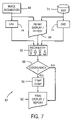
- FIG. 7 is a further flow diagram illustrating another alternative process for temporal image analysis employing a reconciler
- FIG. 8 is a flow diagram illustrating exemplary steps in a typical CAD routine for performing analysis of image data or temporal change images in accordance with the present technique.
- FIG. 9 is a flow chart representing an alternative process for analyzing images created at different points in time interactively in accordance with aspects of the present technique.
- an imaging system 10 is illustrated generally as including an imager 12 for creating image data of a subject 14 .
- the subject may be human or animal, animate or in-animate, such as manufactured parts, naturally occurring subjects and so forth.
- the imaging system 10 may be any suitable type of system that produces digitized image data based upon some imaging physics.
- imaging systems may include MRI systems, PET systems, CT system, tomosythesis systems, X-ray systems, ultrasound systems, among many other imaging modalities.
- the systems may also include conventional photographic imaging systems, that produce digitized image data based upon received radiation of any suitable bandwidth or frequency.
- the imaging system includes an imager 12 coupled to imager control circuitry 16 and image data acquisition circuitry 18 .
- the imager will typically either emit some type of radiation, as with X-ray, CT, tomosynthesis, and other systems.
- Other active imaging systems such as MRI systems, influence subjects by excitation, such as through generation of radio frequency pulses in the presence of controlled magnetic fields.
- the imager is regulated in its operation by the imager control circuitry 16 .
- Such control circuitry may take any suitable form, and typically includes circuitry for activating the imager, receiving radiation or other signals, creating any excitation signals or radiation required for imaging, and so forth.
- the image acquisition circuitry 18 receives and initially processes data received by imager 12 . Such initial processing may include conversion of analog signals to digital signals, filtering of the analog or digital signals, scaling or dynamic range adjustments, and the like.
- the imager control circuitry 16 and the image data acquisition circuitry 18 are generally regulated by some type of system control circuitry 20 . Again, depending upon the nature of the imaging system and the physics involved, the system control circuitry may initiate imaging sequences by exchanging appropriate signals with the imager control circuitry 16 .
- the system control circuitry 20 may also receive the raw or pre-processed image data from the image data acquisition circuitry 18 .
- the system control circuitry 20 may, particularly in more complex systems, be coupled to an operator workstation 22 where an operator selects, configures, and launches examination or imaging sequences.
- the image data either raw, partially processed or fully processed, is typically stored in some type of storage media as represented at reference numeral 24 .
- such storage media may be part of the system control circuitry 20 , the operator workstation 22 , or any other component of the overall system.
- such storage media may include local and remote memory, both magnetic and optical, and may include complex picture archive and communication systems (PACS) designed to store and serve image data upon demand.
- PACS complex picture archive and communication systems
- the operation workstation 22 is shown as coupled to image data processing circuitry 26 .
- image data processing circuitry 26 may actually be distributed throughout the system, and may embody hardware, firmware, and software designed to process the image data to produce reconstructed images for viewing.
- the image processing circuitry 26 performs one or more computer aided diagnosis (CAD) routines on the image data to analyze the data with respect to other image data collected at a different point in time.
- the image data processing circuitry 26 may be local to the imaging system, as illustrated generally in FIG. 1 , or may be completely remote from the system, and simply access the image data, as from the storage media 24 for post-processing.
- FIG. 1 illustrates various remote control/processing/viewing stations 28 that can be coupled to the imaging system by appropriate network links 30 . Such stations may be used for further viewing, analyzing, and processing the image data as described herein.
- the imaging system 10 and indeed other imaging systems of the same or different modalities, is used to create images of a subject at various points in time.
- these images may be accessed, analyzed and compared to determine whether certain particular features are likely present in the image and therefore in the subject.
- temporal change analysis in accordance with the present techniques permits identification of trends in the development of particular features of interest.
- such temporal change analysis can be used to detect the appearance, growth or reduction of certain anatomical features, disease states, naturally occurring or foreign bodies and objects, and so forth.
- FIG. 2 illustrates diagrammatically a temporal change analysis system designated generally by reference numeral 32 .
- the system incorporates an acquisition system 10 which may be of any suitable type or modality as described above with reference to FIG. 1 .
- the system further includes one or more repositories 34 designed to receive and store image data.
- the repository may include any suitable type of memory, typically magnetic media, optical media, and so forth.
- the repository may, in practice, be comprised of a single or many different inter-related storage devices, including devices interconnected via a network.
- the acquisition system 10 produces images or image sequences at different points in time, such as an image set 36 illustrated in FIG. 2 .
- the repository serves to store such image data, as well as image datasets produced at earlier points in time, as indicated at reference numeral 38 in FIG. 2 .
- these various temporally separated image sets may be accessed and analyzed to identify differences or changes between them.
- System 32 further includes image data processing circuitry 40 .
- the image data processing circuitry 40 will include various hardware, firmware and software designed to carryout the functions described herein.
- the processing circuitry may be designed around a general purpose computer or an application-specific computer.
- the image data processing circuitry may, in practice, be a part of the acquisition system 10 , or may be completely separate from the acquisition system. Indeed, the image data processing circuitry 40 may perform its operations in near real time as images are acquired by the acquisition system 10 , or may perform operations solely in post-processing, by accessing image sets 36 and 38 from the repository 34 .
- Circuitry 40 draws upon one or more computer aided detection (CAD) or computer aided diagnosis algorithms as represented generally at reference numeral 42 in FIG. 2 .
- CAD computer aided detection
- the CAD algorithm 42 will analyze image data to recognize structures, edges, regions, and other meaningful relationships between the pixilated image data to segment and classify features potentially of interest in the image data.
- CAX computer aided detection
- Such algorithms may perform operations other than or in addition to the detection and diagnosis of features of interest.
- such algorithms may serve to initiate acquisition, initiate certain processing, initiate or carryout scheduling, recommended actions, processing strings, and so forth.
- the term “CAD” should be understood to include any such additional operations.
- System 32 will typically include an operator workstation 22 which may be the same operator workstation as that described above with reference to the imaging system 10 , or a different operating station.
- the operating station may, itself, incorporate the image data processing circuitry 40 and may be entirely remote from the acquisition system 10 .
- Some type of output system 44 is typically included, such as for creating hardcopy outputs images, reports, and so forth.
- Either operator workstation 22 or output system 44 will also include monitors for viewing reconstructed and temporal change images as discussed below, which may be presented in the form of high resolution and high contrast images permitting users and viewers to analyze, read, annotate and otherwise use the reconstructed images.
- System 32 implements one or more types of processing for analyzing temporal changes between images taken at different points in time. FIGS.
- FIG. 3 illustrates an exemplary temporal change analysis routine 46 in accordance with the present techniques.
- the routine begins with image acquisition as represented at block 48 .
- Acquired image data is associated with images of similar subjects, typically the same subject and the same view, taken at earlier points in time and accessed from repository 34 .
- the system ultimately will apply one or more CAD algorithms as represented at reference numerals 50 and 52 to produce and display or report as represented at block 54 .
- the images acquired at different points in time are processed by a series of modules which interact with the CAD algorithms 50 and 52 as discussed below.
- these modules include a preprocessing module 56 , a segmentation module 58 , a registration module 60 , and a comparison module 62 .
- Image acquisition at block 48 of FIG. 3 enables the temporal change analysis.
- an imaging system is provided as described above and image data is stored in a repository 34 for retrieval.
- the image data analyzed by the system can be the original unprocessed image data from the acquisition system or can be partially or fully processed versions of the original image data.
- the image data may originate in the same or a different modality or imaging system.
- the image data may include digitized data created by scanning and digitization of a conventional medium, such as hardcopy images and film.
- Preprocessing module 56 may serve several functions, depending upon the nature of the image data. For example, module 56 may “normalize” two images to account for differences in acquisition techniques or differences in pre- and post-processing methods. As an example, in X-ray images, if the first image has half the exposure of the second image, gray levels in the first image may be multiplied by a factor of 2 before any further comparison to the second image. The adjustment in the images serves to reduce the differences in the overall image intensity due to image display or technical factors such as differences in dose. Preprocessing module 56 may also perform operations such as scaling, size and orientation adjustments, dynamic range adjustments, and so forth.
- Segmentation module 58 identifies and defines the limits of features of interest in the image data at both points in time. Many types of segmentation are currently available in the art, and these processes are typically identify gradients, intensities and other characteristics of the pixilated data to extract meaningful associations of the data, such as to identify edges, areas, regions, and so forth which may represent recognizable features in the ultimate image. Module 58 therefore provides an automated or manual mechanism for isolating regions of interest in the image data. In many cases of practical interest, the entire image could be the reason of interest, with specific features or subsets of data being identified as potentially representing objects of particular interest.
- Registration module 60 provides for alignment of similar regions or objects of interest in the images taken at different points in time. If the regions of interest for temporal change analysis are small, rigid body registration transformations, including translation, rotation, magnification and shearing may be sufficient to register a pair or images taken at two different points in time. However, if the regions of interest are large, including almost the entire image, warped, elastic transformations can be applied.
- one manner for implementing the warped registration is the use of multi-scale, multi-region, pyramidal approach.
- a different cost function highlighting changes may be optimized at every scale.
- cost functions can be, but are not limited to, correlation methods, such as mathematical correlation and sign-change measurement, or statistical methods such as entropy measurements and mutual information. Images are re-sampled at a given scale and then divided into multiple regions. Separate shift vectors are calculated for different regions. Shift factors are interpolated to produce a smooth shift transformation, which is applied to warp one of the images.
- Weighting functions on shift vectors may be applied during interpolations and these weighting functions can be determined from the image characteristics, such as anatomical features, or the characteristics of the cost function map.
- the images are re-sampled and the warped registration process is repeated at the next higher scale until the pre-determined final scale is reached, or a point is reached where the cost function map has attained a certain pre-determined threshold.
- a combination of rigid registration and elastic transformations may be used.
- Comparison module 62 analyzes dissimilarities between the images.
- a dissimilarity measure between the registered images may be performed in any one of several ways. For example, simple subtractions may be employed, wherein differences are analyzed on a pixel-by-pixel basis and an absolute value of a difference is recorded.
- the value I d represents the value, on a pixel-by-pixel basis, of the difference, comparison or temporal change image.
- the display and report module 54 provides a display and quantification capabilities for the user to visualize or quantify the results of the temporal comparison.
- Results of temporal comparisons may be simultaneously displayed on a display device, such as a monitor, separate from either of the temporal images.
- either or both of the temporal images may be superimposed with one another and with the temporal change image via a logical operator based on a specified criterion.
- color look-up tables for the overlaid images may be used so as to highlight differences or changes that have occurred over time. The resulting combination can be presented in a monochrome or multi-color overlay display.
- the workflow permits analysis of the temporal change image, and of either or both images taken at different points in time via CAD algorithms.
- the temporal change image is presented to the user with the possible addition of the current or previous images, as discussed above.
- the present technique in addition, combines the temporal comparison processing with tools for computer aided analysis of both the original images and the temporal change image. This aspect of the present technique greatly facilitates automation, improvement and simplification of the detection process, particularly of the temporal change image.
- a detailed presentation of a typical CAD technique used for blocks 50 and 52 in FIG. 3 is provided below. In the routine of FIG. 3 , however, features are segmented, classified and presented by CAD algorithm 50 based upon the original image.
- CAD algorithm 52 which may be different from CAD algorithm 50 , particularly in its segmentation and classification schemes, is operated on the temporal comparison data, that is, the temporal change image. Again, one or both of these analyses may be presented by the display and report module 54 . It is anticipated that improved CAD algorithms, or more generally CAX algorithms will be developed for further analysis of the temporal change image data. That is, augmentations and reductions or appearances or disappearances of features of interest at specific locations may be recognized and classified for presentation to the user in diagnosis, treatment, and so forth in the medical context, and in other contexts for analysis of quality or internal structures of subjects of interest.
- FIG. 4 illustrates an alternative temporal change screening routine which facilitates and enhances computational efficiency of the overall process described above.
- an efficient image review is critical, particularly in medical contexts, parcel handling contexts, part quality control contexts, and so forth.
- Providing additional images for review by a human reviewer, such as the temporal change images discussed herein, may have a tendency to decrease productivity, especially in cases where no temporal change, or insignificant temporal changes have occurred.
- the routine of FIG. 4 addresses such workflow issues.
- the solution of FIG. 4 involves initiating temporal comparison only on images in which findings of potential interest are detected. That is, the routine of FIG. 4 , designated generally by reference numeral 64 , includes execution of a particular CAD routine process 66 prior to performing the temporal analysis.
- CAD routine 66 may be different from either CAD routine 50 or 52 discussed above, and serves to initiate the temporal change analysis process. That is, the first CAD algorithm 66 used to analyze the current images may have higher sensitivity and a lower specificity than the algorithms that would normally would be applied to such image data. If the data is found to potentially represent features of particular interests, such as particular anatomies, disease states, lesions, and so forth in the medical context, or inclusions, objects of interest, defects, and so forth in other contexts, the temporal comparison steps described above are initiated. Where such features are not identified by CAD algorithm 66 , a display and report module 54 may present the information resulting from the analysis, or the original images directly.
- FIG. 5 represents a temporal change quantitative analysis routine 68 which allows for measurement and quantification of specific changes between the images.
- acquired images may be displayed directly by the display and report module 54 , and are subjected to a CAD algorithm 66 for initial identification of possible features of interest. If such features are identified, previous images are accessed from repository 34 , and are subjected to the preprocessing, segmentation, registration and comparison modules discussed above. Based upon the comparison, a quantitative analysis module 70 performs measurements of characteristics of the temporal change image. This information, too, can be presented in the display and report module 54 .
- the quantitative analysis module 70 permits actual measurement of specific changes, such as by counting or accumulating a number of pixels or voxels in which significant differences between the images are present. It should be noted that, throughout the present discussion, while reference is made to comparison of pixels and two or more images, all of the present techniques may be applied to three-dimensional images and image datasets, such as to detect changes is three dimensions, rendering the process applicable to situations where the particular orientation or presentation of an object in series of images has changed over time due to actual movement or positioning of the subject in the imaging system. By use of quantitative analysis module 70 , then, features such as suspicious lesions may be automatically detected in a current image, a previous image (or multiple previous images), and the same region identified, with temporal comparison calculated and analyzed for temporal changes.
- FIG. 6 illustrates a temporal change reconciling routine 72 implementing such reconciliation.
- routine 72 current and previous images are accessed and a CAD algorithm 74 is performed on both.
- CAD algorithm 74 will segment and classify features of interest in the image data, and these results will be provided to a reconciler module 76 .
- the reconciler module 76 will, then, recognize whether meaningful differences exist between the results of the CAD analysis.
- the image data, reconstructed images, or results of the analyses may be displayed by the display and report module 54 . If, on the other hand, differences or discrepancies exist between the analyses, a temporal comparison module 80 is launched, and the preprocessing, segmentation, registration, comparison and analysis described above is performed. Temporal comparison module 80 may, furthermore, perform specific CAD algorithms, such as algorithms designed to operate on temporal change images, as well as quantitative analysis algorithms for quantifying changes represented over time, and so forth. The results of such analysis are then presented by the display and report module 54 .
- FIG. 7 represents an alternative temporal change reconciling routine 82 .
- routine 82 current and previous image data is accessed and analyzed via CAD algorithms 74 , as described above with reference to FIG. 6 .
- an initial display and report module 84 presents both images (or multiple images from multiple points in time) to a human observer.
- the human observer may, then, analyze the images to identify features of potential interest for further analysis.
- the input from the human observer, and the results of analysis of both sets of images by CAD algorithm 74 are subjected to a reconciler 86 .
- reconciler 86 identifies discrepancies, that is, concurrences and differences, between either the segmentation or classification performed by the CAD algorithm and by the human observer.
- a final display and report module 92 produces an output for further use and storage. If, on the other hand, such discrepancies are determined between any one of the inputs to reconciler 86 , the temporal comparison module 90 is initiated and preprocessing segmentation, registration, comparison, followed by CAD analysis and quantitative analysis where desired is launched.
- FIG. 8 illustrates and exemplary illustrates an exemplary CAD routine 94 which may be adapted to such applications.
- CAD processing may take many forms, depending upon the type of analysis, type of image, and type of feature of interest.
- FIG. 8 illustrates and exemplary illustrates an exemplary CAD routine 94 which may be adapted to such applications.
- a medical practitioner may derive information regarding a specific disease using temporal data as described herein.
- a CAD algorithm with temporal analysis capabilities for analyzing changes in conditions is therefore proposed.
- features of interest viewable in images may be determined by temporal mammography mass analysis. Such mass identification can be performed for detection alone, such as to identify the presence or absence of suspicious candidate lesions, or may take the form of diagnosis, that is, classification of detected lesions as either benign or malignant.
- input data 96 may be accessed either directly from a source, such as a CT data acquisition system, or from various diagnostic image datasets, such as stored in a data repository as discussed above.
- a segmentation module 98 defines regions of interest to calculate whether features are recognizable in the image data.
- the region of interest may be defined in several ways. For example, the entire dataset may be identified as a region of interest. Alternatively, a part of the data, such as a candidate mass region in a specific region may be considered.
- the segmentation of the region of interest can be performed either manually or automatically. Manual segmentation involves displaying the data and a user delineating a region via an input device, such as a mouse or other suitable interface.
- An automated segmentation algorithm may use prior knowledge, such as the shape, size or other image characteristics of typical similar features to automatically delineate the area of interest.
- a semi-automated method may employ in combination of manual and automated segmentation.
- a feature extraction module 100 which may be an optional module in the routine, involves performing computations on the sourced data. For example, the image-based data in the region of interest may be analyzed to determine statistics such as shape, size, density, curvature, and so forth. On acquisition-based and patient-based data, such as that used in the medical context, the data itself may serve as the extracted features.
- a classification module 102 helps to classify the regions of interest in accordance with any suitable type of classification. For example, in the medical context, masses may be classified by their type, by a probability that they are benign or malignant, and so forth.
- Such classifiers may include a wide range of algorithms, such as Bayesian classifiers, neural networks, rule-based methods, fuzzy logic methods, and so forth.
- the CAD routine is performed once by incorporating features of all data and can be performed in parallel. The parallel operation of CAD algorithms may improve performance of the CAD operations.
- individual operations on the datasets may be influenced by results of individual modules of the CAD algorithm or by combining the results of CAD operations, through logical operators such as AND, OR NOT operations, or combinations of these.
- different CAD algorithms and operations may be implemented to detect multiple features, articles, disease states, and so forth in series or in parallel, as described more fully below with reference to FIG. 9 .
- some type of visualization is usually preferred as indicated at block 104 in FIG. 8 .
- the visualization may be performed via a conventional or special-purpose monitor, hardcopy printouts, film, or any other suitable manner.
- the CAD routine may make use of specific information relating to the images, or general information relating to knowledge with respect to particular features of interest anticipated in the images for the feature extraction and classification steps, as well as for segmentation.
- acquisition parameters 106 are generally relevant to the manner in which features of interest will be presented and can be identified from the images. Such acquisition parameters may typically include the type of system generating the image protocols and settings used to generate the image data, and so forth.
- various types of prior knowledge will be useful in the CAD process as indicated at block 108 . Such prior knowledge may typically include statistical analyses of similar features or objects which may be identified in the images for analysis.
- Such factors may include demographic factors, risk factors, and so forth which may aid in the final classification of any recognized features in the image data.
- some type of training of the CAD algorithm is provided, such as through the incorporation of prior knowledge of known and confirmed features of interest. Training phases of this type may involve computation of several candidate features based on known samples, such as benign and malignant masse in the medical context.
- a feature selection algorithm is then employed to sort the candidate features and select only the useful features for confirming or rejecting certain segmentation, feature extraction and classification candidates. Only useful features or characteristics are preferably retained to reduce redundancy and to improve computational efficiency. Such decisions are typically based on classification of results with different combinations of candidate features.
- the feature selection algorithm employed is also used to reduce the dimensionality from a practical standpoint, therefore further improving computational efficiency.
- a feature set is thus derived that can optimally discriminate between features of interest, such as benign and malignant masses in the medical context.
- This optimal feature set is extracted on regions of interest in the CAD routine.
- Optimal feature selection can be performed using many techniques, such as well-known distance measure techniques, including diversions measures, Bhattacharya distance measures, Mahalanobis distance measures, and so forth.
- the CAD algorithms employed in the present technique may be different from one another, and indeed multiple different CAD algorithms may be used.
- algorithms may be used for parallel analysis of image data, or may be used in series, such as to launch temporal analysis only where particular features of interest may be present or viewable in the image data.
- Parallel CAD algorithms may also be employed for the same or different features, or with different levels of sensitivity and specificity, with reconcilers being employed as discussed above, where appropriate.
- temporal analysis CAD algorithms will continue to be developed for operation on temporal change images specifically. These will include algorithms for quantitative analysis of changes over time.
- CAD algorithms may be performed or implemented in parallel as represented generally in FIG. 9 .
- the interactive temporal analysis CAD routine designated generally by reference numeral 112 in FIG. 9 , allows for temporal changes between images to be analyzed through interactive or interleaved operation of CAD modules of the type discussed above.
- image datasets 96 are accessed from different points in time, and segmentation is performed on each by a segmentation module 98 of two parallel CAD algorithms.
- the CAD algorithms may be of the same nature, or may differ from one another, such as in sensitivity or specificity, or may be adapted to identify different features of interest.
- the segmented images, or segmented portions of the images are registered by a specially-adapted registration module.
- registration module 114 may be generally similar to that of registration module 60 discussed above, or may be specially adapted for different types of images or segmentation where the segmentation performed by the CAD algorithms of the routine are different.
- the results of the registration are provided to a comparison module 116 which determines whether the results of the segmentation are convergent or divergent.
- the output of the registration may also be provided to feature extraction modules 100 . From this point on, data between the modules of each CAD algorithm may be exchanged or used in a complimentary fashion to enhance feature extraction, classification and eventual visualization. Certain results of the CAD algorithms are thus merged prior to the feature identification.
- the resulting process allows for temporal differences between images to be identified, taking into account feature commonalities and differences, to arrive at a synergistic analysis of the temporal data represented by the different image datasets.
Landscapes
- Engineering & Computer Science (AREA)
- Health & Medical Sciences (AREA)
- Life Sciences & Earth Sciences (AREA)
- Physics & Mathematics (AREA)
- Medical Informatics (AREA)
- General Physics & Mathematics (AREA)
- Theoretical Computer Science (AREA)
- General Health & Medical Sciences (AREA)
- Nuclear Medicine, Radiotherapy & Molecular Imaging (AREA)
- Radiology & Medical Imaging (AREA)
- Surgery (AREA)
- Computer Vision & Pattern Recognition (AREA)
- Biomedical Technology (AREA)
- Molecular Biology (AREA)
- Pathology (AREA)
- Animal Behavior & Ethology (AREA)
- Biophysics (AREA)
- Public Health (AREA)
- Veterinary Medicine (AREA)
- Heart & Thoracic Surgery (AREA)
- High Energy & Nuclear Physics (AREA)
- Quality & Reliability (AREA)
- Optics & Photonics (AREA)
- Multimedia (AREA)
- Measuring And Recording Apparatus For Diagnosis (AREA)
- Apparatus For Radiation Diagnosis (AREA)
- Magnetic Resonance Imaging Apparatus (AREA)
- Image Processing (AREA)
- Image Analysis (AREA)
Priority Applications (4)
| Application Number | Priority Date | Filing Date | Title |
|---|---|---|---|
| US10/723,861 US7492931B2 (en) | 2003-11-26 | 2003-11-26 | Image temporal change detection and display method and apparatus |
| FR0412533A FR2862788B1 (fr) | 2003-11-26 | 2004-11-25 | Procede et systeme d'analyse de changements temporels d'image |
| DE200410057026 DE102004057026A1 (de) | 2003-11-26 | 2004-11-25 | Erfassung zeitlicher Bildveränderungen und Darstellungsverfahren und -vorrichtung |
| JP2004342633A JP4669268B2 (ja) | 2003-11-26 | 2004-11-26 | 画像の経時変化を検出し表示する方法及び装置 |
Applications Claiming Priority (1)
| Application Number | Priority Date | Filing Date | Title |
|---|---|---|---|
| US10/723,861 US7492931B2 (en) | 2003-11-26 | 2003-11-26 | Image temporal change detection and display method and apparatus |
Publications (2)
| Publication Number | Publication Date |
|---|---|
| US20050113961A1 US20050113961A1 (en) | 2005-05-26 |
| US7492931B2 true US7492931B2 (en) | 2009-02-17 |
Family
ID=34552756
Family Applications (1)
| Application Number | Title | Priority Date | Filing Date |
|---|---|---|---|
| US10/723,861 Expired - Lifetime US7492931B2 (en) | 2003-11-26 | 2003-11-26 | Image temporal change detection and display method and apparatus |
Country Status (4)
| Country | Link |
|---|---|
| US (1) | US7492931B2 (https=) |
| JP (1) | JP4669268B2 (https=) |
| DE (1) | DE102004057026A1 (https=) |
| FR (1) | FR2862788B1 (https=) |
Cited By (15)
| Publication number | Priority date | Publication date | Assignee | Title |
|---|---|---|---|---|
| US20050265606A1 (en) * | 2004-05-27 | 2005-12-01 | Fuji Photo Film Co., Ltd. | Method, apparatus, and program for detecting abnormal patterns |
| US20080063301A1 (en) * | 2006-09-12 | 2008-03-13 | Luca Bogoni | Joint Segmentation and Registration |
| US20080226145A1 (en) * | 2007-03-05 | 2008-09-18 | Fujifilm Corporation | Image processing apparatus and computer readable media containing image processing program |
| US20090022386A1 (en) * | 2003-11-26 | 2009-01-22 | Kelly Lynn Karau | Methods and systems for computer aided targeting |
| US20100087756A1 (en) * | 2008-10-02 | 2010-04-08 | Artann Laboratories, Inc. | Method of characterization and differentiation of tissue |
| US20100256991A1 (en) * | 2007-09-27 | 2010-10-07 | Canon Kabushiki Kaisha | Medical diagnosis support apparatus |
| US20110013220A1 (en) * | 2009-07-20 | 2011-01-20 | General Electric Company | Application server for use with a modular imaging system |
| US20110152676A1 (en) * | 2009-12-21 | 2011-06-23 | General Electric Company | Intra-operative registration for navigated surgical procedures |
| US8243882B2 (en) | 2010-05-07 | 2012-08-14 | General Electric Company | System and method for indicating association between autonomous detector and imaging subsystem |
| US20130197370A1 (en) * | 2012-01-30 | 2013-08-01 | The Johns Hopkins University | Automated Pneumothorax Detection |
| US9092691B1 (en) | 2014-07-18 | 2015-07-28 | Median Technologies | System for computing quantitative biomarkers of texture features in tomographic images |
| US20150320325A1 (en) * | 2014-05-06 | 2015-11-12 | Koninklijke Philips N.V. | Devices, Systems, and Methods for Vessel Assessment |
| US20160239969A1 (en) * | 2015-02-14 | 2016-08-18 | The Trustees Of The University Of Pennsylvania | Methods, systems, and computer readable media for automated detection of abnormalities in medical images |
| US20170132798A1 (en) * | 2013-03-15 | 2017-05-11 | Mim Software Inc. | Population-guided deformable registration |
| WO2022017666A1 (en) * | 2020-07-21 | 2022-01-27 | F.Hoffmann-La Roche Ag | Method of generating a metric to quantitatively represent an effect of a treatment |
Families Citing this family (58)
| Publication number | Priority date | Publication date | Assignee | Title |
|---|---|---|---|---|
| US20050254720A1 (en) * | 2004-05-17 | 2005-11-17 | Kar-Han Tan | Enhanced surgical visualizations with multi-flash imaging |
| US7912268B2 (en) * | 2004-06-14 | 2011-03-22 | Canon Kabushiki Kaisha | Image processing device and method |
| JP4949264B2 (ja) * | 2004-11-19 | 2012-06-06 | コーニンクレッカ フィリップス エレクトロニクス エヌ ヴィ | 医療画像データ内の腫瘍境界を自動的に検出及び区分するシステム及び方法 |
| US8849068B2 (en) * | 2005-04-08 | 2014-09-30 | Canon Kabushiki Kaisha | Image management system, image management method, and program |
| EP1886257A1 (en) | 2005-05-11 | 2008-02-13 | Optosecurity Inc. | Method and system for screening luggage items, cargo containers or persons |
| US7991242B2 (en) * | 2005-05-11 | 2011-08-02 | Optosecurity Inc. | Apparatus, method and system for screening receptacles and persons, having image distortion correction functionality |
| DE102005036998B4 (de) * | 2005-08-05 | 2014-11-20 | Siemens Aktiengesellschaft | Vorrichtung zur automatischen Detektion von Auffälligkeiten in medizinischen Bilddaten |
| US7769216B2 (en) * | 2005-12-29 | 2010-08-03 | Hologic, Inc. | Facilitating comparison of medical images |
| GB2455926B (en) * | 2006-01-30 | 2010-09-01 | Axellis Ltd | Method of preparing a medical restraint |
| FR2897182A1 (fr) | 2006-02-09 | 2007-08-10 | Gen Electric | Procede de traitement d'images de projection en tomosynthese pour une detection de signes radiologiques |
| DE102006008509A1 (de) * | 2006-02-23 | 2007-08-02 | Siemens Ag | Verfahren und Vorrichtung zur verbesserten automatischen Detektion von Auffälligkeiten in medizinischen Bilddaten |
| US7899232B2 (en) | 2006-05-11 | 2011-03-01 | Optosecurity Inc. | Method and apparatus for providing threat image projection (TIP) in a luggage screening system, and luggage screening system implementing same |
| RU2481061C2 (ru) * | 2006-06-02 | 2013-05-10 | Конинклейке Филипс Электроникс, Н.В. | Система комбинированной визуализации и рабочая станция с поддержкой структурированной проверки гипотез |
| US20070280556A1 (en) * | 2006-06-02 | 2007-12-06 | General Electric Company | System and method for geometry driven registration |
| US8494210B2 (en) | 2007-03-30 | 2013-07-23 | Optosecurity Inc. | User interface for use in security screening providing image enhancement capabilities and apparatus for implementing same |
| US7747076B2 (en) * | 2006-12-21 | 2010-06-29 | Fujifilm Corporation | Mass segmentation using mirror image of region of interest |
| EP1956552B1 (en) * | 2007-02-09 | 2011-06-08 | Agfa-Gevaert | Visual enhancement of interval changes using a temporal subtraction technique |
| EP1956553B1 (en) * | 2007-02-09 | 2009-08-19 | Agfa-Gevaert | Visual enhancement of interval changes using a temporal subtraction technique. |
| DE602007002693D1 (de) * | 2007-02-09 | 2009-11-19 | Agfa Gevaert | Visuelle Hervorhebung von Intervalländerungen mittels einer Zeitsubtraktionstechnik |
| JP2008259622A (ja) * | 2007-04-11 | 2008-10-30 | Fujifilm Corp | レポート作成支援装置およびそのプログラム |
| DE102007028226B4 (de) * | 2007-06-20 | 2015-11-19 | Siemens Aktiengesellschaft | Auswertungsverfahren für eine zeitliche Sequenz von Röntgenbildern und hiermit korrespondierende Gegenstände |
| US7630533B2 (en) * | 2007-09-20 | 2009-12-08 | Hologic, Inc. | Breast tomosynthesis with display of highlighted suspected calcifications |
| US9076203B2 (en) * | 2007-11-26 | 2015-07-07 | The Invention Science Fund I, Llc | Image guided surgery with dynamic image reconstruction |
| DE102008040803A1 (de) * | 2008-07-28 | 2010-02-04 | Carl Zeiss Surgical Gmbh | Verfahren zur quantitativen Darstellung des Blutflusses |
| DE102008040807B4 (de) * | 2008-07-28 | 2017-09-21 | Carl Zeiss Meditec Ag | Verfahren zur Korrektur von den Blutfluss darstellenden Bilddaten, Medizinisches Gerät und Analysesystem |
| DE102008040804B4 (de) * | 2008-07-28 | 2021-07-29 | Carl Zeiss Meditec Ag | Verfahren, Operationsmikroskop und Analysesystem zur quantitativen Darstellung des Blutflusses |
| DE102008040802B4 (de) * | 2008-07-28 | 2014-09-18 | Carl Zeiss Meditec Ag | Verfahren zur quantitativen Darstellung des Blutflusses sowie Operationsmikroskop und Analysesystem |
| JP2010029481A (ja) * | 2008-07-29 | 2010-02-12 | Univ Of Tsukuba | 腫瘍の経過観察レポート自動作成診断支援システム |
| JP5390805B2 (ja) * | 2008-08-07 | 2014-01-15 | キヤノン株式会社 | 出力装置およびその方法、プログラム、記録媒体 |
| DE102008045275A1 (de) * | 2008-09-01 | 2009-12-10 | Siemens Aktiengesellschaft | Verfahren zur Registrierung von Bilddaten |
| US8223916B2 (en) * | 2009-03-31 | 2012-07-17 | Hologic, Inc. | Computer-aided detection of anatomical abnormalities in x-ray tomosynthesis images |
| US9084568B2 (en) * | 2009-08-05 | 2015-07-21 | Telesystems Co., Ltd. | Radiation imaging apparatus and imaging method using radiation |
| JP5478328B2 (ja) * | 2009-09-30 | 2014-04-23 | 富士フイルム株式会社 | 診断支援システム、診断支援プログラムおよび診断支援方法 |
| US8744148B2 (en) * | 2010-08-24 | 2014-06-03 | Varian Medical Systems International Ag | Method and apparatus regarding iterative processes as pertain to medical imaging information |
| FR2975804B1 (fr) * | 2011-05-27 | 2022-06-17 | Lvmh Rech | Procede de caracterisation du teint de la peau ou des phaneres |
| US9111331B2 (en) | 2011-09-07 | 2015-08-18 | Rapiscan Systems, Inc. | X-ray inspection system that integrates manifest data with imaging/detection processing |
| DE102012201169A1 (de) * | 2012-01-27 | 2013-08-01 | Siemens Aktiengesellschaft | Automatische Registrierung von Bildpaaren von medizinischen Bilddatensätzen |
| GB201203883D0 (en) * | 2012-03-05 | 2012-04-18 | King S College London | Method and system to assist 2D-3D image registration |
| JP6050016B2 (ja) * | 2012-03-30 | 2016-12-21 | フクダ電子株式会社 | 心電図データ出力装置 |
| DE102012205711B4 (de) * | 2012-04-05 | 2023-08-31 | Siemens Healthcare Gmbh | Verfahren zum Betreiben eines bildgebenden Diagnosegerätes sowie medizinisches bildgebendes System |
| JP6036009B2 (ja) * | 2012-08-28 | 2016-11-30 | 大日本印刷株式会社 | 医用画像処理装置、およびプログラム |
| JP6310469B2 (ja) * | 2012-10-31 | 2018-04-11 | ボルケーノ コーポレイション | マルチモダリティ医療システムにおいての依存性に基づくスタートアップ |
| US9855698B2 (en) * | 2013-08-07 | 2018-01-02 | Massachusetts Institute Of Technology | Automatic process control of additive manufacturing device |
| EP2886059A1 (de) * | 2013-09-25 | 2015-06-24 | CureFab Technologies GmbH | 4d-pulskorrektur mit deformierbarer registrierung |
| CN105246415B (zh) * | 2013-12-05 | 2018-05-01 | 奥林巴斯株式会社 | 超声波观测装置以及超声波观测装置的动作方法 |
| KR102294194B1 (ko) * | 2014-08-05 | 2021-08-26 | 삼성전자주식회사 | 관심영역의 시각화 장치 및 방법 |
| JP6080268B2 (ja) * | 2014-09-29 | 2017-02-15 | 富士フイルム株式会社 | 医用画像保存処理装置および方法並びにプログラム |
| US20160113546A1 (en) * | 2014-10-23 | 2016-04-28 | Khalifa University of Science, Technology & Research | Methods and systems for processing mri images to detect cancer |
| US10751943B2 (en) * | 2015-08-24 | 2020-08-25 | Siemens Healthcare Gmbh | Personalized creation from medical imaging |
| WO2017104700A1 (ja) * | 2015-12-17 | 2017-06-22 | 国立大学法人東京大学 | 画像処理装置および画像処理方法 |
| PL3764281T3 (pl) | 2016-02-22 | 2025-02-10 | Rapiscan Systems, Inc. | Sposoby identyfikacji broni palnej na obrazach radiograficznych |
| CN114712730A (zh) | 2017-05-30 | 2022-07-08 | 反射医疗公司 | 用于实时图像引导放射治疗的方法 |
| US11648418B2 (en) | 2017-06-22 | 2023-05-16 | Reflexion Medical, Inc. | Systems and methods for biological adaptive radiotherapy |
| EP3684468B1 (en) | 2017-09-22 | 2024-03-20 | RefleXion Medical, Inc. | Systems for shuttle mode radiation delivery |
| JP7191105B2 (ja) * | 2017-12-18 | 2022-12-16 | コーニンクレッカ フィリップス エヌ ヴェ | 運動補償磁気共鳴イメージング |
| CN119701229A (zh) | 2018-02-13 | 2025-03-28 | 反射医疗公司 | 光束站治疗计划和放射输送方法 |
| CN116912160A (zh) * | 2022-04-19 | 2023-10-20 | 佳能医疗系统株式会社 | 医用图像处理装置、变化度计算方法及非易失性存储介质 |
| US12561808B2 (en) * | 2022-04-19 | 2026-02-24 | Canon Medical Systems Corporation | Medical image-processing apparatus, change-degree calculation method, and non-volatile computer-readable medium |
Citations (10)
| Publication number | Priority date | Publication date | Assignee | Title |
|---|---|---|---|---|
| US5359513A (en) * | 1992-11-25 | 1994-10-25 | Arch Development Corporation | Method and system for detection of interval change in temporally sequential chest images |
| US5361763A (en) * | 1993-03-02 | 1994-11-08 | Wisconsin Alumni Research Foundation | Method for segmenting features in an image |
| US5598481A (en) * | 1994-04-29 | 1997-01-28 | Arch Development Corporation | Computer-aided method for image feature analysis and diagnosis in mammography |
| US5807256A (en) * | 1993-03-01 | 1998-09-15 | Kabushiki Kaisha Toshiba | Medical information processing system for supporting diagnosis |
| US6075879A (en) * | 1993-09-29 | 2000-06-13 | R2 Technology, Inc. | Method and system for computer-aided lesion detection using information from multiple images |
| US20010007593A1 (en) | 1999-12-27 | 2001-07-12 | Akira Oosawa | Method and unit for displaying images |
| US6421454B1 (en) * | 1999-05-27 | 2002-07-16 | Litton Systems, Inc. | Optical correlator assisted detection of calcifications for breast biopsy |
| US6836558B2 (en) * | 2000-03-28 | 2004-12-28 | Arch Development Corporation | Method, system and computer readable medium for identifying chest radiographs using image mapping and template matching techniques |
| US6909792B1 (en) * | 2000-06-23 | 2005-06-21 | Litton Systems, Inc. | Historical comparison of breast tissue by image processing |
| US7054473B1 (en) * | 2001-11-21 | 2006-05-30 | R2 Technology, Inc. | Method and apparatus for an improved computer aided diagnosis system |
Family Cites Families (3)
| Publication number | Priority date | Publication date | Assignee | Title |
|---|---|---|---|---|
| JPH04200452A (ja) * | 1990-11-29 | 1992-07-21 | Shimadzu Corp | 画像表示装置 |
| JP4702971B2 (ja) * | 1999-11-10 | 2011-06-15 | 株式会社東芝 | コンピュータ支援診断システム |
| JP2002219123A (ja) * | 2001-01-26 | 2002-08-06 | Mitsubishi Space Software Kk | 投影変換装置及び方法並びに経時差分画像作成装置及び方法 |
-
2003
- 2003-11-26 US US10/723,861 patent/US7492931B2/en not_active Expired - Lifetime
-
2004
- 2004-11-25 FR FR0412533A patent/FR2862788B1/fr not_active Expired - Fee Related
- 2004-11-25 DE DE200410057026 patent/DE102004057026A1/de not_active Withdrawn
- 2004-11-26 JP JP2004342633A patent/JP4669268B2/ja not_active Expired - Fee Related
Patent Citations (10)
| Publication number | Priority date | Publication date | Assignee | Title |
|---|---|---|---|---|
| US5359513A (en) * | 1992-11-25 | 1994-10-25 | Arch Development Corporation | Method and system for detection of interval change in temporally sequential chest images |
| US5807256A (en) * | 1993-03-01 | 1998-09-15 | Kabushiki Kaisha Toshiba | Medical information processing system for supporting diagnosis |
| US5361763A (en) * | 1993-03-02 | 1994-11-08 | Wisconsin Alumni Research Foundation | Method for segmenting features in an image |
| US6075879A (en) * | 1993-09-29 | 2000-06-13 | R2 Technology, Inc. | Method and system for computer-aided lesion detection using information from multiple images |
| US5598481A (en) * | 1994-04-29 | 1997-01-28 | Arch Development Corporation | Computer-aided method for image feature analysis and diagnosis in mammography |
| US6421454B1 (en) * | 1999-05-27 | 2002-07-16 | Litton Systems, Inc. | Optical correlator assisted detection of calcifications for breast biopsy |
| US20010007593A1 (en) | 1999-12-27 | 2001-07-12 | Akira Oosawa | Method and unit for displaying images |
| US6836558B2 (en) * | 2000-03-28 | 2004-12-28 | Arch Development Corporation | Method, system and computer readable medium for identifying chest radiographs using image mapping and template matching techniques |
| US6909792B1 (en) * | 2000-06-23 | 2005-06-21 | Litton Systems, Inc. | Historical comparison of breast tissue by image processing |
| US7054473B1 (en) * | 2001-11-21 | 2006-05-30 | R2 Technology, Inc. | Method and apparatus for an improved computer aided diagnosis system |
Non-Patent Citations (1)
| Title |
|---|
| Pennec, et al., Non-rigid MR/US Registration for Tracking Brain Deformations, Sophia Antipolis Cedex, France. |
Cited By (29)
| Publication number | Priority date | Publication date | Assignee | Title |
|---|---|---|---|---|
| US20090022386A1 (en) * | 2003-11-26 | 2009-01-22 | Kelly Lynn Karau | Methods and systems for computer aided targeting |
| US7756314B2 (en) * | 2003-11-26 | 2010-07-13 | Ge Medical Systems Global Technology Company, Llc | Methods and systems for computer aided targeting |
| US20050265606A1 (en) * | 2004-05-27 | 2005-12-01 | Fuji Photo Film Co., Ltd. | Method, apparatus, and program for detecting abnormal patterns |
| US20080063301A1 (en) * | 2006-09-12 | 2008-03-13 | Luca Bogoni | Joint Segmentation and Registration |
| US20080226145A1 (en) * | 2007-03-05 | 2008-09-18 | Fujifilm Corporation | Image processing apparatus and computer readable media containing image processing program |
| US8285013B2 (en) * | 2007-03-05 | 2012-10-09 | Fujifilm Corporation | Method and apparatus for detecting abnormal patterns within diagnosis target image utilizing the past positions of abnormal patterns |
| US20100256991A1 (en) * | 2007-09-27 | 2010-10-07 | Canon Kabushiki Kaisha | Medical diagnosis support apparatus |
| US8142368B2 (en) * | 2008-10-02 | 2012-03-27 | Artann Laboratories Inc. | Method of characterization and differentiation of tissue |
| US20100087756A1 (en) * | 2008-10-02 | 2010-04-08 | Artann Laboratories, Inc. | Method of characterization and differentiation of tissue |
| US8786873B2 (en) | 2009-07-20 | 2014-07-22 | General Electric Company | Application server for use with a modular imaging system |
| US20110013220A1 (en) * | 2009-07-20 | 2011-01-20 | General Electric Company | Application server for use with a modular imaging system |
| US20110152676A1 (en) * | 2009-12-21 | 2011-06-23 | General Electric Company | Intra-operative registration for navigated surgical procedures |
| US8694075B2 (en) | 2009-12-21 | 2014-04-08 | General Electric Company | Intra-operative registration for navigated surgical procedures |
| US8243882B2 (en) | 2010-05-07 | 2012-08-14 | General Electric Company | System and method for indicating association between autonomous detector and imaging subsystem |
| US20130197370A1 (en) * | 2012-01-30 | 2013-08-01 | The Johns Hopkins University | Automated Pneumothorax Detection |
| US8914097B2 (en) * | 2012-01-30 | 2014-12-16 | The Johns Hopkins University | Automated pneumothorax detection |
| US20150065849A1 (en) * | 2012-01-30 | 2015-03-05 | The Johns Hopkins University | Automated Pneumothorax Detection |
| US9277877B2 (en) * | 2012-01-30 | 2016-03-08 | The Johns Hopkins University | Automated pneumothorax detection |
| US20170132798A1 (en) * | 2013-03-15 | 2017-05-11 | Mim Software Inc. | Population-guided deformable registration |
| US11763469B2 (en) | 2013-03-15 | 2023-09-19 | Mim Software Inc. | Population-guided deformable registration |
| US10311587B2 (en) * | 2013-03-15 | 2019-06-04 | Mim Software, Inc. | Population-guided deformable registration |
| US20150320325A1 (en) * | 2014-05-06 | 2015-11-12 | Koninklijke Philips N.V. | Devices, Systems, and Methods for Vessel Assessment |
| US11744544B2 (en) | 2014-05-06 | 2023-09-05 | Philips Image Guided Therapy Corporation | Devices, systems, and methods for vessel assessment |
| US12109065B2 (en) | 2014-05-06 | 2024-10-08 | Philips Image Guided Therapy Corporation | Devices, systems, and methods for vessel assessment |
| US9092691B1 (en) | 2014-07-18 | 2015-07-28 | Median Technologies | System for computing quantitative biomarkers of texture features in tomographic images |
| US9984283B2 (en) * | 2015-02-14 | 2018-05-29 | The Trustees Of The University Of Pennsylvania | Methods, systems, and computer readable media for automated detection of abnormalities in medical images |
| US20160239969A1 (en) * | 2015-02-14 | 2016-08-18 | The Trustees Of The University Of Pennsylvania | Methods, systems, and computer readable media for automated detection of abnormalities in medical images |
| WO2022017666A1 (en) * | 2020-07-21 | 2022-01-27 | F.Hoffmann-La Roche Ag | Method of generating a metric to quantitatively represent an effect of a treatment |
| US12608807B2 (en) | 2020-07-21 | 2026-04-21 | Hoffmann-La Roche Inc. | Method of generating a metric to quantitatively represent an effect of a treatment |
Also Published As
| Publication number | Publication date |
|---|---|
| FR2862788B1 (fr) | 2007-04-06 |
| JP4669268B2 (ja) | 2011-04-13 |
| JP2005177470A (ja) | 2005-07-07 |
| DE102004057026A1 (de) | 2005-06-23 |
| US20050113961A1 (en) | 2005-05-26 |
| FR2862788A1 (fr) | 2005-05-27 |
Similar Documents
| Publication | Publication Date | Title |
|---|---|---|
| US7492931B2 (en) | Image temporal change detection and display method and apparatus | |
| US7653263B2 (en) | Method and system for volumetric comparative image analysis and diagnosis | |
| US10111632B2 (en) | System and method for breast cancer detection in X-ray images | |
| US6125194A (en) | Method and system for re-screening nodules in radiological images using multi-resolution processing, neural network, and image processing | |
| US6760468B1 (en) | Method and system for the detection of lung nodule in radiological images using digital image processing and artificial neural network | |
| EP3611733A1 (en) | Searching a medical reference image | |
| US20070052700A1 (en) | System and method for 3D CAD using projection images | |
| US7512284B2 (en) | Volumetric image enhancement system and method | |
| US20070003118A1 (en) | Method and system for projective comparative image analysis and diagnosis | |
| Rao et al. | Early detection of lung cancer using machine learning technique | |
| WO2023001089A1 (en) | Generative adversarial network-based lossless image compression model for cross-sectional imaging | |
| Gupta et al. | A novel diagnostic framework for breast cancer: Combining deep learning with mammogram-DBT feature fusion | |
| US20070014448A1 (en) | Method and system for lateral comparative image analysis and diagnosis | |
| Oliveira et al. | From 3D to 2D: Transferring knowledge for rib segmentation in chest X-rays | |
| Sreelekshmi et al. | Unleashing the power of hierarchical variational autoencoder for predicting breast cancer | |
| Ma | Deep learning‐based image processing for financial audit risk quantification in healthcare | |
| US12374460B2 (en) | Uncertainty estimation in medical imaging | |
| Depeursinge et al. | 3D case–based retrieval for interstitial lung diseases | |
| Dimililer et al. | Image preprocessing phase with artificial intelligence methods on medical images | |
| Nagarathinam et al. | Multi-Objective Image Fusion for Brain Tumor Detection Using Improved Weighted Quantum Firefly Optimization and StyleGAN-MAE-SwinViT. | |
| Kim et al. | Predictive Analysis of Breast Cancer from Full-Field Digital Mammography Images using Residual Network | |
| Cifci et al. | Deep learning algorithms for diagnosis of breast cancer with maximum likelihood estimation | |
| Tkachenko et al. | A mammography data management application for federated learning | |
| Gomathi et al. | Computer aided medical diagnosis system for detection of lung cancer nodules: a survey | |
| Ramesh et al. | Automatic Endoscopic Ultrasound Station Recognition with Limited Data |
Legal Events
| Date | Code | Title | Description |
|---|---|---|---|
| AS | Assignment |
Owner name: GE MEDICAL SYSTEMS GLOBAL TECHNOLOGY COMPANY, LLC, Free format text: ASSIGNMENT OF ASSIGNORS INTEREST;ASSIGNORS:SABOL, JOHN M.;FUNG, MAGGI MEI-KEI;BATTLE, VIANNEY PIERRE;AND OTHERS;REEL/FRAME:014757/0052 Effective date: 20031125 |
|
| FEPP | Fee payment procedure |
Free format text: PAYOR NUMBER ASSIGNED (ORIGINAL EVENT CODE: ASPN); ENTITY STATUS OF PATENT OWNER: LARGE ENTITY |
|
| STCF | Information on status: patent grant |
Free format text: PATENTED CASE |
|
| FPAY | Fee payment |
Year of fee payment: 4 |
|
| FPAY | Fee payment |
Year of fee payment: 8 |
|
| MAFP | Maintenance fee payment |
Free format text: PAYMENT OF MAINTENANCE FEE, 12TH YEAR, LARGE ENTITY (ORIGINAL EVENT CODE: M1553); ENTITY STATUS OF PATENT OWNER: LARGE ENTITY Year of fee payment: 12 |