US7469909B2 - Chuck for receiving tools operated by rotating around the axis thereof - Google Patents
Chuck for receiving tools operated by rotating around the axis thereof Download PDFInfo
- Publication number
- US7469909B2 US7469909B2 US10/515,212 US51521205A US7469909B2 US 7469909 B2 US7469909 B2 US 7469909B2 US 51521205 A US51521205 A US 51521205A US 7469909 B2 US7469909 B2 US 7469909B2
- Authority
- US
- United States
- Prior art keywords
- clamp
- chuck
- bit
- cavity
- sleeve
- Prior art date
- Legal status (The legal status is an assumption and is not a legal conclusion. Google has not performed a legal analysis and makes no representation as to the accuracy of the status listed.)
- Expired - Fee Related, expires
Links
Images


Classifications
-
- B—PERFORMING OPERATIONS; TRANSPORTING
- B25—HAND TOOLS; PORTABLE POWER-DRIVEN TOOLS; MANIPULATORS
- B25B—TOOLS OR BENCH DEVICES NOT OTHERWISE PROVIDED FOR, FOR FASTENING, CONNECTING, DISENGAGING OR HOLDING
- B25B23/00—Details of, or accessories for, spanners, wrenches, screwdrivers
- B25B23/0007—Connections or joints between tool parts
- B25B23/0035—Connection means between socket or screwdriver bit and tool
-
- B—PERFORMING OPERATIONS; TRANSPORTING
- B25—HAND TOOLS; PORTABLE POWER-DRIVEN TOOLS; MANIPULATORS
- B25B—TOOLS OR BENCH DEVICES NOT OTHERWISE PROVIDED FOR, FOR FASTENING, CONNECTING, DISENGAGING OR HOLDING
- B25B23/00—Details of, or accessories for, spanners, wrenches, screwdrivers
- B25B23/02—Arrangements for handling screws or nuts
- B25B23/08—Arrangements for handling screws or nuts for holding or positioning screw or nut prior to or during its rotation
- B25B23/12—Arrangements for handling screws or nuts for holding or positioning screw or nut prior to or during its rotation using magnetic means
-
- Y—GENERAL TAGGING OF NEW TECHNOLOGICAL DEVELOPMENTS; GENERAL TAGGING OF CROSS-SECTIONAL TECHNOLOGIES SPANNING OVER SEVERAL SECTIONS OF THE IPC; TECHNICAL SUBJECTS COVERED BY FORMER USPC CROSS-REFERENCE ART COLLECTIONS [XRACs] AND DIGESTS
- Y10—TECHNICAL SUBJECTS COVERED BY FORMER USPC
- Y10S—TECHNICAL SUBJECTS COVERED BY FORMER USPC CROSS-REFERENCE ART COLLECTIONS [XRACs] AND DIGESTS
- Y10S279/00—Chucks or sockets
- Y10S279/904—Quick change socket
- Y10S279/905—Quick change socket with ball detent
-
- Y—GENERAL TAGGING OF NEW TECHNOLOGICAL DEVELOPMENTS; GENERAL TAGGING OF CROSS-SECTIONAL TECHNOLOGIES SPANNING OVER SEVERAL SECTIONS OF THE IPC; TECHNICAL SUBJECTS COVERED BY FORMER USPC CROSS-REFERENCE ART COLLECTIONS [XRACs] AND DIGESTS
- Y10—TECHNICAL SUBJECTS COVERED BY FORMER USPC
- Y10T—TECHNICAL SUBJECTS COVERED BY FORMER US CLASSIFICATION
- Y10T279/00—Chucks or sockets
- Y10T279/17—Socket type
- Y10T279/17666—Radially reciprocating jaws
- Y10T279/17692—Moving-cam actuator
- Y10T279/17743—Reciprocating cam sleeve
- Y10T279/17752—Ball or roller jaws
-
- Y—GENERAL TAGGING OF NEW TECHNOLOGICAL DEVELOPMENTS; GENERAL TAGGING OF CROSS-SECTIONAL TECHNOLOGIES SPANNING OVER SEVERAL SECTIONS OF THE IPC; TECHNICAL SUBJECTS COVERED BY FORMER USPC CROSS-REFERENCE ART COLLECTIONS [XRACs] AND DIGESTS
- Y10—TECHNICAL SUBJECTS COVERED BY FORMER USPC
- Y10T—TECHNICAL SUBJECTS COVERED BY FORMER US CLASSIFICATION
- Y10T279/00—Chucks or sockets
- Y10T279/34—Accessory or component
- Y10T279/3406—Adapter
Definitions
- the invention relates to a chuck for receiving tools which can be used by rotation about their axis, in particular screwdriver inserts, having an insertion portion having a receiving cavity which has a cross-sectional area that is not round, in which receiving cavity the tool can be secured by means of a holding element associated with the wall of the cavity against being pulled out of the receiving cavity, which holding element can be deactivated by a sliding movement of an actuating member, in particular in the form of an actuating sleeve, the tool being supported at the rear in the receiving cavity.
- Chucks of this type are described by DE 29 34 428 and DE 199 32 369.
- the polygonal portion of a bit is fitted into a polygonal bore in an insertion portion.
- a holding element which is formed by a ball acts on the outer surface of the bit, in particular on its edge or edge cutout.
- the ball is pressed radially inward onto a polygonal flank or into the corner cutout by an inclined flank of an actuating sleeve.
- the force required is supplied by a compression spring which spring loads the actuating sleeve and counter to the spring force of which the sleeve is displaced in the release direction.
- a magnet which forms the base of the receiving cavity is provided to augment the holding force.
- short and thin bits can only be removed from the chuck with difficulty counter to the force of the magnet.
- the invention is based on the object of further developing a chuck of the generic type in a manner that is advantageous for use, and in particular of facilitating removal of the bit.
- Claim 1 provides firstly and substantially that the tool is displaceable out of the supported position toward the opening of the receiving cavity by actuation of the actuating sleeve. According to an advantageous refinement of the invention, this is achieved by an auxiliary tool removal member that is displaceable by and along with the actuating sleeve.
- This auxiliary tool removal member may be a pusher associated with the base of the receiving cavity. This pusher can be dragged along by the actuating sleeve. This dragging-along movement preferably takes place in the same direction as the displacement of the actuating sleeve.
- the pusher prefferably to engage on the rear end face of the tool in order to displace it in part out of the receiving cavity, so that the length of the portion of the tool projecting out of the receiving cavity on which it is possible to grip is increased. Moreover, if the tool bears against a magnet forming the base of the receiving cavity, the end face of the tool is spaced apart from the magnet as a result of the pusher displacement. A gap is formed. The holding force exerted on the tool by the magnet is reduced as a result of this gap.
- the holding element is preferably a pressure piece which acts on the clamp-in shank of the tool in the radial direction. This pressure piece may be formed as a ball.
- the pressure piece is formed and mounted in the same way as described in DE 101 41 668.7.
- the actuating sleeve is displaceable counter to the force of a spring.
- the pusher may be formed by a portion of a spring of this type.
- the pusher there is also provision for the pusher to be acted on only by a portion of the actuating sleeve spring.
- a rear end portion of the actuating sleeve spring can engage through a slot.
- the pusher is formed by an angled-off end portion of a compression coil spring that is seated on the insertion portion.
- This compression coil spring may at one end be supported on a support ring which is seated in an axially fixed position in a circumferential groove in the insertion portion.
- the other end of the compression coil spring is supported on a stop shoulder that is formed by a drawn-in collar of the actuating sleeve.
- This end of the compression coil spring has a radially inwardly directed portion. This portion projects through the slot in the insertion portion and into the receiving cavity. An angled portion of the end of the compression coil spring can then be displaced along the wall of the cavity when the actuating sleeve is displaced.
- the pusher or the spring end has a certain freedom of movement with respect to the end face or with respect to an inclined end edge of the bit, so that first of all the clamping surface of the actuating sleeve is displaced in order to allow the pressure piece to move aside. Only when this retention of the tool has been released does the pusher or the end of the spring come to bear against the bit in order to displace it in the outward direction within the receiving cavity.
- a further aspect of the same invention provides for the end face of the bit to bear against a magnet.
- means which can be used to separate the end face of the bit from the magnet enable the end face of the bit to be brought out of bearing contact with the magnet. This can be effected by means of the measures described above.
- the magnet is spaced apart from the bit, i.e. the bit retains its insertion position within the insertion cavity. As a result of the magnet being spaced apart from the end face of the bit, the holding force exerted on the bit by the magnet is considerably reduced, so that even small and in particular short bits can be removed from the chuck without problems.
- an annular region of the end face of the bit which is formed in particular as a bevel, to be supported on a radial projection.
- This radial projection may surround a cavity in which the magnet is located.
- the magnet may be fixedly connected to a portion of the clamp-in portion.
- This clamp-in portion has a polygonal cross-sectional shape.
- This clamp-in portion may be disposed in a rotationally fixed but axially slidable manner within the insertion portion of the chuck, where it is mounted in an axially slidable manner.
- the clamp-in portion may be axially displaceable between two stops, one stop corresponding to the axial position of the clamp-in portion in which the magnet bears in surface contact against the end face of the bit.
- the other stop may be associated with the spaced-apart position of the magnet from the end face of the bit.
- This chuck functions in the following way: if the clamp-in portion is retained in the chuck of an electric screwdriver, the chuck can be moved into a position of readiness for receiving as a result of sliding movement of the actuating sleeve. However, this is not necessary in the preferred configuration of the chuck, since the ball can move aside backward when it comes into contact with the rear bevel of the bit. If the bit is fitted into the receiving cavity, it bears areally against the base of the cavity, which is formed by the axially displaceable magnet. It is held by the magnet. However, the bit is also held by the ball. If the bit is to be removed from the chuck, the actuating sleeve is displaced away from the clamp-in portion, i.e.
- a further aspect of the invention likewise deals with the problem of simplifying the removal of a bit from a chuck of the generic type.
- the actuating member can be locked in its position in which it holds the holding element deactivated as a result of a sliding movement of a clamp-in portion with respect to the sleeve portion into which the clamp-in portion fits.
- the holding element is moved out of its active position, so that the bit can be pulled out without its being necessary for the actuating member to be retained in its release position.
- This function is particularly advantageous if that end of the clamp-in portion which is located in the sleeve portion bears a magnet which, in the clamping position, bears against the end face of the bit.
- Displacing the clamp-in portion in part out of the sleeve causes the magnet to be separated from the bit.
- the end edge of the bit is supported against a circlip that is located in a circumferential groove in the sleeve portion.
- the axial displaceability of the clamp-in portion is stop-limited. This is achieved by means of a split washer which is located in a circumferential groove in the sleeve portion. It forms a radial projection which is located in a circumferential groove in the clamp-in portion.
- the axial width of the circumferential groove in the clamp-in portion determines the displacement travel of the latter.
- the actuating member is preferably locked in place by at least one blocking member which is located in a wall cutout in the sleeve portion and moves into a blocking recess in the actuating member.
- the blocking body may be a ball and the blocking recess may be formed by an annular groove.
- the diameter of the blocking body is greater than the wall thickness of the sleeve portion. The result of this is that the blocking body either projects beyond the outer wall of the sleeve portion or projects into the sleeve cavity. If the blocking body projects beyond the outer wall of the sleeve, it can enter into the blocking recess in the actuating member in order to hold it in the release position.
- the blocking body in this case bears on a lateral surface portion of the clamp-in portion and is supported at the rear by the latter. With the clamp-in portion slid inward, the blocking body can move into a moving-aside niche in the clamp-in portion.
- the clamp-in portion is retained against axial movement in this position by the actuating member, which is held in the locking position by a spring. In this position, which corresponds to the clamping position of the actuating member, the blocking body is prevented by the cylindrical inner cavity wall of the actuating member from being displaced in the radially outward direction. It is preferable for the sleeve which forms the actuating member to be displaced from the locking position into the release position in the removal direction of the bit.
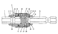
- FIG. 1 shows the exemplary embodiment partially in longitudinal section, the tip of the bit and a partial region of the clamp-in portion of the chuck being broken away,
- FIG. 2 shows a section on line II-II in FIG. 1 ,
- FIG. 3 shows a section on line III-III in FIG. 1 ,
- FIG. 4 shows an illustration corresponding to FIG. 1 with the actuating sleeve actuated
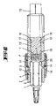
- FIG. 5 shows an illustration of a second exemplary embodiment of the invention corresponding to FIG. 1 of the first exemplary embodiment
- FIG. 6 shows the second exemplary embodiment illustrated in FIG. 5 with the magnet displaced rearward
- FIG. 7 shows a further exemplary embodiment corresponding to FIG. 5 .
- FIG. 8 shows the further exemplary embodiment on the basis of an illustration corresponding to FIG. 6 .
- FIG. 9 shows a further exemplary embodiment of the invention in perspective illustration
- FIG. 10 shows a longitudinal section through the exemplary embodiment illustrated in FIG. 9 , with the actuating sleeve in the blocking position
- FIG. 11 shows an illustration corresponding to FIG. 10 , with the sleeve displaced into the release position
- FIG. 12 shows a follow-up illustration to FIG. 11 , with an axially displaced clamp-in portion
- FIG. 13 shows an illustration corresponding to FIG. 10 while a bit is being slid in, with the actuating sleeve in the locking position
- FIG. 14 shows an illustration corresponding to FIG. 10 with the bit slid in.
- the chuck has an insertion portion 3 and a hexagonal clamp-in portion 15 .
- This insertion portion 3 may consist of metal and at one end has a receiving cavity 2 for a screwdriver insert 1 , in the form of a bit.
- a clamp-in shank 15 At the other end, a clamp-in shank 15 , the hexagon portion of which can be fitted into a chuck of an electric screwdriver, projects out of the insertion portion.
- the clamp-in portion 15 can be pressed into a cavity in the insertion portion 3 .
- the receiving cavity 2 has a hexagonal cross section.
- a window is located in the region of an edge of the receiving cavity 2 .
- a ball 4 which forms the holding element and the diameter of which is greater than the wall thickness, so that the ball 4 can extend into the receiving cavity 2 , in order there to hold the bit by being supported on the corner points of a corner cutout of the polygonal shank of the bit.
- the ball 4 is acted on by an inclined clamping flank 10 of an actuating sleeve 5 .
- the actuating sleeve 5 is displaceable, counter to the restoring force of a compression coil spring 11 , from the clamping position illustrated in FIG.
- the compression coil spring 11 is supported for this on an annular support shoulder located in a groove in the insertion portion 3 .
- This support shoulder is formed by a ring 14 against which the actuating sleeve 5 is also supported in the clamping position.
- the rear end of the spring has an extension 6 which protrudes into a slot 12 in the insertion portion 3 .
- This extension 6 projects into the receiving cavity 2 in the region of a corner of the receiving cavity 2 , and together with an angled-off portion forms a pusher 8 which, in the clamping position illustrated in FIG. 1 , projects only slightly beyond the base 7 of the receiving cavity 2 .
- the pusher which is formed by the spring end portion, does not project beyond the base 7 in the clamping position.
- the base 7 of the receiving cavity 2 is formed by a cylindrical magnet 9 .
- a free pocket is formed between the outer wall of the magnet 9 and the polygon corner of the receiving cavity 2 .
- the spring end portion 6 is guided in this free pocket.
- the pusher may also be formed by a separate component. It is also provided that the pusher engages on the rear end face of the bit approximately in the center of the receiving cavity 2 .
- the pusher can also be displaced in the opposite direction to the actuating sleeve 5 . This can be realized, for example, by means of a reversing lever mechanism, if the actuating pusher has to be displaced toward the clamp-in portion 15 in order to release the holding element 4 .
- the device functions in the following way: starting from the clamping position illustrated in FIG. 1 , in which the ball 4 is located in front of a shoulder of the bit 1 and therefore the bit cannot be pulled out of the receiving cavity 2 , the actuating sleeve 5 is displaced in the direction indicated by arrow L, with the spring 11 being stressed. During this sliding displacement of the actuating sleeve 5 , the ball 4 acquires space to move aside radially outward, so that the holding action of the ball 4 is eliminated. In principle, the bit could be pulled out of the receiving cavity 2 after this initial displacement of the actuating sleeve 5 .
- a bit 1 is fitted into a receiving cavity 2 in an insertion portion 3 , which overall is formed as a polygonal sleeve.
- a ball 4 which is acted on by a spring in the direction of the opening of the receiving cavity 2 , fits into a slot in the wall. The ball is acted on in the radially inward direction by means of a clamping flank 10 of an actuating sleeve 5 .
- the portion 15 ′ of a clamp-in portion 15 fits into the rear part of the insertion portion 3 .
- the clamp-in portion 15 is formed as a hexagon and is intended to be able to be fitted by means of its free end into the chuck of an electric screwdriver.
- the portion 15 ′of the clamp-in portion 15 fits in the insertion portion 3 in a rotationally fixed but axially slidable manner.
- a magnet 9 In front of the head of the portion 15 there is a magnet 9 .
- the magnet 9 is fixedly connected to the portion 15 .
- the axial displaceability of the clamp-in portion 15 is stop-limited. This is achieved by means of a projection 17 which can be stamped or rolled in after assembly of the clamp-in portion 15 . This projection 17 engages in a circumferential cutout 16 in the portion 15 ′.
- An annular bevel 19 which surrounds the annular surface 1 ′ of the bit is supported on a radial projection 20 .
- This radial projection 20 leaves a central opening in which the magnet 9 is located.
- the surface 7 of the magnet 9 bears areally against the end face 1 ′. If an axial force is exerted on the clamp-in portion 15 , this force is transmitted via the magnet 9 directly into the end face 1 ′ of the bit 1 . On the other hand, if a pull which is greater than the holding force of the magnet 9 on the end face 1 ′ of the bit 1 is exerted on the clamp-in portion 15 , the magnet 9 is removed from the end face 1 ′ of the bit 1 .
- the result of the magnet 9 being removed from the bit 1 is that the holding force exerted by the magnet 9 on the bit 1 is considerably reduced, so that the bit can be pulled out of the receiving cavity 2 when the actuating sleeve has been moved into the release position (cf. FIG. 6 ).
- the pulling force can be applied by the actuating sleeve 5 being displaced toward the opening of the receiving cavity 2 when a clamp-in portion 15 has been clamped in a chuck of an electric screwdriver or the like. At the same time as this displacement, the ball 4 is released in order to enable it to move aside outward in the radial direction.
- FIGS. 7 and 8 substantially corresponds to the exemplary embodiment of FIGS. 5 and 6 .
- the pertinent factor in this embodiment is the stop-limited holding of the clamp-in portion 15 in the polygonal cavity in the insertion portion 3 .
- the hexagonal clamp-in portion 15 has corner cutouts in which a split washer 23 surrounding the clamp-in portion 15 is located. This split washer is located in an annular cutout 25 in the insertion portion 3 .
- the annular cutout 25 in the insertion portion 3 is formed by a sleeve portion fitted onto the end of the insertion portion 3 .
- the end portion of the insertion portion 3 forms an annular step portion 24 .
- a wall portion 22 of widened diameter of the sleeve end portion 21 has been fitted onto this annular step portion 24 , where it is held tightly in place.
- the actuating sleeve 5 is formed in two parts.
- An inner portion 5 ′ which slides directly along the sleeve portion 21 , has a circumferential groove that is wide in the axial direction.
- a second sleeve portion 5 ′′ made from plastic is located rotatably in this circumferential groove.
- the chuck can also be held on this second sleeve portion 5 ′′ during rotary operation.
- the sleeve 5 ′′ can rotate freely in the groove receiving it.
- the bit illustrated in FIGS. 10 to 12 has a flute 29 .
- a holding ball 4 projects into the receiving cavity 2 in regions and bears on a rear flute flank, so that the bit cannot be pulled out of the receiving cavity 2 .
- the end-face bevel of the bit butts against a circlip 20 which is located in a circumferential groove in the receiving cavity 2 .
- the ball 4 is acted on by a clamping flank 10 of the sleeve part 5 .
- the sleeve 5 is held in the locking position illustrated in FIG. 10 by means of a spring 11 .
- the rear end face of the bit 1 bears against an end face 7 of a clamp-in portion 15 .
- the end face 7 is formed by a magnet 9 which is located in a bore 30 in the end of the clamp-in portion 15 .
- the sleeve portion 21 has two wall cutouts 31 located diametrically opposite one another.
- the diameter of the substantially circular wall cutout 31 corresponds to slightly more than the diameter of the latching ball 27 located in the wall cutout 31 .
- the diameter of the latching ball 27 is greater than the wall thickness of the sleeve portion 21 , so that the latching ball 27 either projects in part into the cavity 18 in the sleeve portion 21 or projects beyond the outer wall of the sleeve portion 21 .
- the latching ball 27 projects into the cavity in the sleeve portion 21 .
- a portion of the clamp-in portion 15 is fitted into this cavity 18 in an axially moveable manner.
- the clamp-in portion 15 has two diametrically opposite moving-aside hollows 28 . These hollows may be formed by a circumferential groove.
- the clamp-in portion 15 has been displaced with respect to the sleeve portion 21 .
- a lateral surface portion of the clamp-in portion 15 provides support for the latching ball 27 on the sleeve inner side, so that the ball cannot move out of the annular cutout 26 in the actuating sleeve 5 .
- the actuating sleeve is held in its release position.
- the displacement travel of the clamp-in portion is limited by a circlip 17 which is located in an inner groove in the sleeve portion 21 and is located such that it projects radially inward into an annular cutout 16 in the clamp-in portion 15 .
- the axial width of the cutout 16 defines the axial displacement travel of the clamp-in portion 15 .
- the holding ball 4 can move aside radially outward, so that the bit can be removed.
- a new bit is fitted into the chuck in the reverse order.
- the bit in the operating position illustrated in FIG. 12 , the bit can be inserted into its receiving cavity 2 until its end face or the bevel on the end face comes into contact with the circlip 20 .
- the clamp-in portion 15 can be displaced out of the position illustrated in FIG. 12 into the position illustrated in FIGS. 10 or 11 either by the magnetic force of the magnet 9 then becoming active or by mechanical force.
- the latching ball 27 can move aside radially inward into the moving-aside hollow 28 or circumferential groove, so that the actuating sleeve 5 is released to enable it to be displaced into the locking position ( FIG. 10 ). This displacement takes place as a result of the force of the stressed spring 11 .
- a bit it is also possible for a bit to be fitted into the receiving cavity 2 with the actuating sleeve in the locking position ( FIG. 13 ).
- the holding ball 4 is located in an axially displaceable manner in a window in the sleeve wall. It is displaceable in the insertion direction of the bit counter to the force of a spring 32 .
- the holding ball 4 can be displaced in the insertion direction of the bit, with simultaneous stressing of the spring 32 . It then slides along the clamping flank 10 and can be displaced radially outward until it moves beyond the lateral surface of the bit.
- the bit can then be fitted fully into the receiving cavity 2 until it reaches the stop position (cf. FIG. 13 ). In this position, the holding ball 4 prevents the bit from being pulled out even without the holding ball being located in the corner cutout.
- the holding ball 4 is displaced by the spring 32 into the end region of the window, so that the holding ball 4 can enter into a corner cutout of the bit (cf. FIG. 14 ).
- the clamping flank 10 acts on the holding ball 4 in the radial direction.
- the latching ball 27 is located in the moving-aside niche 28 in the clamp-in portion 15 , so that the clamp-in portion 15 is retained in the axial direction on the sleeve portion 21 .
Landscapes
- Engineering & Computer Science (AREA)
- Mechanical Engineering (AREA)
- Details Of Spanners, Wrenches, And Screw Drivers And Accessories (AREA)
Applications Claiming Priority (5)
| Application Number | Priority Date | Filing Date | Title |
|---|---|---|---|
| DE10225505.9 | 2002-06-10 | ||
| DE10225505 | 2002-06-10 | ||
| DE10254339.9A DE10254339B4 (de) | 2002-06-10 | 2002-11-21 | Futter zur Aufnahme von durch Drehen um ihre Achse verwendbare Werkzeuge |
| DE10254339.9 | 2002-11-21 | ||
| PCT/EP2003/004920 WO2003103901A2 (de) | 2002-06-10 | 2003-05-12 | Futter zur aufnahme von durch drehen um ihre achse verwendbare werkzeuge |
Publications (2)
| Publication Number | Publication Date |
|---|---|
| US20060097464A1 US20060097464A1 (en) | 2006-05-11 |
| US7469909B2 true US7469909B2 (en) | 2008-12-30 |
Family
ID=29737583
Family Applications (1)
| Application Number | Title | Priority Date | Filing Date |
|---|---|---|---|
| US10/515,212 Expired - Fee Related US7469909B2 (en) | 2002-06-10 | 2003-05-12 | Chuck for receiving tools operated by rotating around the axis thereof |
Country Status (5)
| Country | Link |
|---|---|
| US (1) | US7469909B2 (de) |
| EP (1) | EP1513653B1 (de) |
| JP (1) | JP4238211B2 (de) |
| AU (1) | AU2003240620A1 (de) |
| WO (1) | WO2003103901A2 (de) |
Cited By (44)
| Publication number | Priority date | Publication date | Assignee | Title |
|---|---|---|---|---|
| US20080023924A1 (en) * | 2006-07-27 | 2008-01-31 | Hsin Yin Enterprise Co., Ltd. | Tool retaining or connecting device |
| US20080100005A1 (en) * | 2006-11-01 | 2008-05-01 | Tsai-Ching Chen | Chuck |
| US20080121075A1 (en) * | 2006-11-23 | 2008-05-29 | Meng Chi-Fen | Device for locking and releasing a scrwe bit |
| US20080217870A1 (en) * | 2007-03-07 | 2008-09-11 | Makita Corporation | Bit mounting devices |
| US20090174157A1 (en) * | 2008-01-08 | 2009-07-09 | Hsin Ying Enterprise Co., Ltd. | Tool connecting device |
| US20090311062A1 (en) * | 2008-06-11 | 2009-12-17 | Bobby Hu | Chuck for Bit |
| US20100007102A1 (en) * | 2008-07-14 | 2010-01-14 | Ho-Tien Chen | Bit holder |
| US7740249B1 (en) * | 2006-05-01 | 2010-06-22 | Bradshaw Medical, Inc. | Holder for replaceable tools |
| US7810817B1 (en) * | 2006-11-20 | 2010-10-12 | Bradshaw Medical, Inc. | Holder for replaceable tools |
| US20120104702A1 (en) * | 2010-11-03 | 2012-05-03 | Bobby Hu | Quick-Release Bit Adapter |
| US20120326401A1 (en) * | 2009-02-27 | 2012-12-27 | Black & Decker Inc. | Bit Retention Device |
| US20130001897A1 (en) * | 2011-06-30 | 2013-01-03 | Chen Bo-Shen | Connecting rod assembly for connecting a work head |
| US20130247392A1 (en) * | 2012-03-20 | 2013-09-26 | Milwaukee Electric Tool Corporation | Reciprocating saw blade clamp |
| US8695461B2 (en) | 2010-12-22 | 2014-04-15 | Black & Decker Inc. | Cleanable magnetic nut driver |
| US20140197609A1 (en) * | 2013-01-16 | 2014-07-17 | A-Tina Tools Co., Ltd. | Hand Tool Plate Clamp |
| US20150202689A1 (en) * | 2014-01-22 | 2015-07-23 | Good Year Hardware Co., Ltd. | Tool bit adapter having a position-limit rod |
| US9156147B2 (en) | 2012-02-15 | 2015-10-13 | Black & Decker Inc. | Quick change bit holder with ring magnet |
| EP2937181A1 (de) | 2014-04-22 | 2015-10-28 | HILTI Aktiengesellschaft | Werkzeughalter |
| US9227309B2 (en) | 2012-02-15 | 2016-01-05 | Black & Decker Inc. | Quick change bit holder with ring magnet |
| US9447803B1 (en) | 2012-12-20 | 2016-09-20 | Holmed, Llc | AO quick connect interface |
| US20160271768A1 (en) * | 2015-03-17 | 2016-09-22 | Chervon (Hk) Limited | Bit holder and combination of tool bit and bit holder |
| US9458890B1 (en) | 2012-12-20 | 2016-10-04 | Holmed, Llc | Square quick connect interface |
| US9505108B2 (en) | 2012-02-15 | 2016-11-29 | Black & Decker Inc. | Bit holder with floating magnet sleeve |
| US20170028538A1 (en) * | 2015-07-29 | 2017-02-02 | Black & Decker Inc. | Drive guide for fastening bits |
| USD780548S1 (en) | 2015-07-22 | 2017-03-07 | Ac (Macao Commercial Offshore) Limited | Power tool |
| USD789761S1 (en) | 2015-11-02 | 2017-06-20 | Black & Decker Inc. | Torsion bit |
| USD806493S1 (en) | 2015-07-22 | 2018-01-02 | Tti (Macao Commercial Offshore) Limited | Tool adapter |
| US9943946B2 (en) | 2012-02-15 | 2018-04-17 | Black & Decker Inc. | Tool bits with floating magnet sleeves |
| US20180245706A1 (en) * | 2017-02-24 | 2018-08-30 | Bobby Hu | Quick detachable and adjustable magnetic seat for sleeve |
| US10150205B2 (en) | 2012-02-15 | 2018-12-11 | Black & Decker Inc. | Fastening tools with floating magnet sleeves |
| US20190061119A1 (en) * | 2017-08-30 | 2019-02-28 | Xiamen Nanchbit Precision Tools Co., Ltd. | Quick-change connecting mechanism and quick-change screwdriver |
| USD877590S1 (en) | 2018-07-20 | 2020-03-10 | Milwaukee Electric Tool Corporation | Tool accessory |
| USD906081S1 (en) | 2018-08-20 | 2020-12-29 | Milwaukee Electric Tool Corporation | Driver bit |
| USD922166S1 (en) | 2018-10-09 | 2021-06-15 | Milwaukee Electric Tool Corporation | Tool bit adapter |
| US11065744B2 (en) | 2018-07-20 | 2021-07-20 | Milwaukee Electric Tool Corporation | Tool bit holder |
| US11179831B2 (en) * | 2018-07-11 | 2021-11-23 | Milwaukee Electric Tool Corporation | Lockable drive socket adapter |
| US11235448B1 (en) | 2020-09-08 | 2022-02-01 | Apex Brands, Inc. | Overload protected impact driving device |
| US11342101B2 (en) | 2018-07-20 | 2022-05-24 | Milwaukee Electric Tool Corporation | Magnetism booster assembly |
| US11364606B2 (en) * | 2020-03-18 | 2022-06-21 | Apex Brands, Inc | Radial band wedge impact driving device |
| US11413729B2 (en) | 2018-08-20 | 2022-08-16 | Milwaukee Electric Tool Corporation | Tool bit |
| US11491554B2 (en) | 2019-07-18 | 2022-11-08 | Apex Brands, Inc. | Compact flexible impact bit holder |
| US11529687B2 (en) | 2019-12-16 | 2022-12-20 | Kennametal, Inc. | Rotary cutting tool and tool assembly |
| US11583989B2 (en) | 2020-04-03 | 2023-02-21 | Apex Brands, Inc. | Multi-start threaded impact driving device |
| US11780063B2 (en) | 2017-10-10 | 2023-10-10 | Milwaukee Electric Tool Corporation | Power tool to tool bit extension adapter |
Families Citing this family (15)
| Publication number | Priority date | Publication date | Assignee | Title |
|---|---|---|---|---|
| US8484884B2 (en) * | 2004-07-26 | 2013-07-16 | Andrew Zuk | Fishing lure and kit |
| US20070108706A1 (en) * | 2005-02-25 | 2007-05-17 | Jore Corporation | Tool connector having multiple locking positions |
| US20080256774A1 (en) * | 2006-03-01 | 2008-10-23 | Jacques Rajotte | Screw driving method |
| DE102007058522A1 (de) * | 2007-12-05 | 2009-06-10 | Robert Bosch Gmbh | Haltevorrichtung für Bits |
| JP5117258B2 (ja) * | 2008-04-01 | 2013-01-16 | 株式会社マキタ | 自動変速式動力工具 |
| US8381830B2 (en) * | 2009-05-05 | 2013-02-26 | Black & Decker Inc. | Power tool with integrated bit retention device |
| US8622401B2 (en) * | 2009-02-27 | 2014-01-07 | Black & Decker Inc. | Bit retention device |
| CN102463553A (zh) * | 2010-11-05 | 2012-05-23 | 胡厚飞 | 快脱起子接杆 |
| CN102773825B (zh) * | 2011-05-11 | 2015-02-11 | 胡厚飞 | 快脱起子接杆 |
| DE102012101894A1 (de) * | 2012-03-06 | 2013-09-12 | Tkr Spezialwerkzeuge Gmbh | Werkzeugverbindung |
| JP2014050909A (ja) * | 2012-09-06 | 2014-03-20 | Vessel Industrial Co Ltd | 回転工具用アタッチメント |
| CN104227633B (zh) * | 2013-06-06 | 2016-05-18 | 苏州宝时得电动工具有限公司 | 冲击扳手 |
| DE102017112949B4 (de) * | 2017-06-13 | 2021-07-29 | Good Year Hardware Co., Ltd. | Adapter für Werkzeugaufsatz mit magnetischer Anziehung |
| WO2019031275A1 (ja) * | 2017-08-10 | 2019-02-14 | 工機ホールディングス株式会社 | 電動工具 |
| WO2020154725A1 (en) * | 2019-01-25 | 2020-07-30 | Gauthier Biomedical, Inc. | Improved shaft securing mechanism for a tool |
Citations (23)
| Publication number | Priority date | Publication date | Assignee | Title |
|---|---|---|---|---|
| US4188041A (en) * | 1977-05-23 | 1980-02-12 | The Boeing Company | Motor quick-change chuck system for tool having cylindrically shaped adapter portion |
| DE2934428A1 (de) | 1979-08-25 | 1981-03-26 | Wera-Werk Hermann Werner Gmbh & Co, 42349 Wuppertal | Spannfutter fuer werkzeug-einsatzstuecke, insbesondere schraubendreherbits |
| DE4207337C1 (de) | 1992-03-07 | 1993-06-09 | Helfer & Co Kg, 3260 Rinteln, De | |
| US5398946A (en) | 1993-12-29 | 1995-03-21 | Poly-Tech Industries | Chuck having one-step lock and release |
| EP0685300A1 (de) | 1994-05-02 | 1995-12-06 | Matthew B. Jore | Umkehrbares Bohrantriebswerkzeug |
| DE19923006A1 (de) | 1998-12-19 | 2000-06-29 | Holland Letz Felo Werkzeug | Spannfutter für auswechselbare Werkzeugeinsätze |
| WO2000066329A1 (en) | 1999-05-03 | 2000-11-09 | Maxtech Manufacturing Inc. | Quick-connect mechanism |
| DE19932369A1 (de) | 1999-07-13 | 2001-01-18 | Werner Hermann Wera Werke | Futter für Schraubendrehereinsätze |
| US6199872B1 (en) | 1999-08-13 | 2001-03-13 | Maxtech Consumer Products, L.L.C. | Quick-release mechanism for screwdriver bits and the like |
| US6270085B1 (en) * | 1999-10-01 | 2001-08-07 | Tsai-Ching Chen | Chuck device for tool bits |
| EP1122032A2 (de) | 2000-02-03 | 2001-08-08 | WILLI HAHN GmbH & CO. KG | Spannfutter für Schaftenden von Werkzeugseinsatzstücken, insbesondere Schraubendreherbits |
| US20010043841A1 (en) | 1999-11-15 | 2001-11-22 | Wienhold James L. | Locking quick-change chuck assembly |
| WO2001096052A1 (en) | 2000-06-09 | 2001-12-20 | Jore Corporation | Workpiece connector for a power tool |
| US6345560B1 (en) * | 1997-06-02 | 2002-02-12 | Wera-Werk Hermann Werner Gmbh & Co. | Clamping chuck for bits |
| DE10141668A1 (de) | 2001-08-25 | 2003-03-06 | Werner Hermann Wera Werke | Spannfutter für Werkzeuge, insbesondere Schraubendreherbits |
| US6637755B2 (en) * | 2002-03-22 | 2003-10-28 | Tsai-Ching Chen | Chuck device for miniature tool bits |
| US6644150B2 (en) * | 2002-01-25 | 2003-11-11 | Tsai-Ching Chen | Tool bit holding device with an improved retaining effect |
| DE10219418A1 (de) * | 2002-05-02 | 2003-11-13 | Werner Hermann Wera Werke | Freilaufende Hülse |
| US20040081523A1 (en) * | 2001-02-09 | 2004-04-29 | Vasudeva Kailash C. | Irregular-shank tools and drivers therefor |
| US6931967B1 (en) * | 2004-02-26 | 2005-08-23 | Sheng-Ming Chang | Connecting shaft device for screws |
| US20060181033A1 (en) * | 2005-02-14 | 2006-08-17 | Ho-Tien Chen | Bit holder |
| US7111530B2 (en) * | 2004-06-28 | 2006-09-26 | Ping Wen Huang | Screwdriver fast connector |
| US7261023B2 (en) * | 2003-06-25 | 2007-08-28 | Vessel Industrial Co., Ltd. | Bit holder device |
-
2003
- 2003-05-12 EP EP03730006A patent/EP1513653B1/de not_active Expired - Lifetime
- 2003-05-12 US US10/515,212 patent/US7469909B2/en not_active Expired - Fee Related
- 2003-05-12 WO PCT/EP2003/004920 patent/WO2003103901A2/de active Application Filing
- 2003-05-12 JP JP2004511008A patent/JP4238211B2/ja not_active Expired - Fee Related
- 2003-05-12 AU AU2003240620A patent/AU2003240620A1/en not_active Abandoned
Patent Citations (27)
| Publication number | Priority date | Publication date | Assignee | Title |
|---|---|---|---|---|
| US4188041A (en) * | 1977-05-23 | 1980-02-12 | The Boeing Company | Motor quick-change chuck system for tool having cylindrically shaped adapter portion |
| DE2934428A1 (de) | 1979-08-25 | 1981-03-26 | Wera-Werk Hermann Werner Gmbh & Co, 42349 Wuppertal | Spannfutter fuer werkzeug-einsatzstuecke, insbesondere schraubendreherbits |
| DE4207337C1 (de) | 1992-03-07 | 1993-06-09 | Helfer & Co Kg, 3260 Rinteln, De | |
| US5398946A (en) | 1993-12-29 | 1995-03-21 | Poly-Tech Industries | Chuck having one-step lock and release |
| EP0685300A1 (de) | 1994-05-02 | 1995-12-06 | Matthew B. Jore | Umkehrbares Bohrantriebswerkzeug |
| US6345560B1 (en) * | 1997-06-02 | 2002-02-12 | Wera-Werk Hermann Werner Gmbh & Co. | Clamping chuck for bits |
| DE19923006A1 (de) | 1998-12-19 | 2000-06-29 | Holland Letz Felo Werkzeug | Spannfutter für auswechselbare Werkzeugeinsätze |
| WO2000066329A1 (en) | 1999-05-03 | 2000-11-09 | Maxtech Manufacturing Inc. | Quick-connect mechanism |
| US6695321B2 (en) * | 1999-05-03 | 2004-02-24 | Maxtech Manufacturing Inc. | Quick-connect mechanism |
| US6311989B1 (en) * | 1999-07-13 | 2001-11-06 | Werner Hermann Wera Werke | Chuck for screwdriver inserts |
| DE19932369A1 (de) | 1999-07-13 | 2001-01-18 | Werner Hermann Wera Werke | Futter für Schraubendrehereinsätze |
| US6199872B1 (en) | 1999-08-13 | 2001-03-13 | Maxtech Consumer Products, L.L.C. | Quick-release mechanism for screwdriver bits and the like |
| US6270085B1 (en) * | 1999-10-01 | 2001-08-07 | Tsai-Ching Chen | Chuck device for tool bits |
| US20010043841A1 (en) | 1999-11-15 | 2001-11-22 | Wienhold James L. | Locking quick-change chuck assembly |
| US6457916B2 (en) * | 1999-11-15 | 2002-10-01 | Insty-Bit, Inc. | Locking quick-change chuck assembly |
| EP1122032A2 (de) | 2000-02-03 | 2001-08-08 | WILLI HAHN GmbH & CO. KG | Spannfutter für Schaftenden von Werkzeugseinsatzstücken, insbesondere Schraubendreherbits |
| WO2001096052A1 (en) | 2000-06-09 | 2001-12-20 | Jore Corporation | Workpiece connector for a power tool |
| US20040081523A1 (en) * | 2001-02-09 | 2004-04-29 | Vasudeva Kailash C. | Irregular-shank tools and drivers therefor |
| US7063332B2 (en) * | 2001-08-25 | 2006-06-20 | Wera Werk Hermann Werner Gmbh & Co.Kg | Chuck for tools, especially screwdriver bits |
| DE10141668A1 (de) | 2001-08-25 | 2003-03-06 | Werner Hermann Wera Werke | Spannfutter für Werkzeuge, insbesondere Schraubendreherbits |
| US6644150B2 (en) * | 2002-01-25 | 2003-11-11 | Tsai-Ching Chen | Tool bit holding device with an improved retaining effect |
| US6637755B2 (en) * | 2002-03-22 | 2003-10-28 | Tsai-Ching Chen | Chuck device for miniature tool bits |
| DE10219418A1 (de) * | 2002-05-02 | 2003-11-13 | Werner Hermann Wera Werke | Freilaufende Hülse |
| US7261023B2 (en) * | 2003-06-25 | 2007-08-28 | Vessel Industrial Co., Ltd. | Bit holder device |
| US6931967B1 (en) * | 2004-02-26 | 2005-08-23 | Sheng-Ming Chang | Connecting shaft device for screws |
| US7111530B2 (en) * | 2004-06-28 | 2006-09-26 | Ping Wen Huang | Screwdriver fast connector |
| US20060181033A1 (en) * | 2005-02-14 | 2006-08-17 | Ho-Tien Chen | Bit holder |
Cited By (67)
| Publication number | Priority date | Publication date | Assignee | Title |
|---|---|---|---|---|
| US7740249B1 (en) * | 2006-05-01 | 2010-06-22 | Bradshaw Medical, Inc. | Holder for replaceable tools |
| US20080023924A1 (en) * | 2006-07-27 | 2008-01-31 | Hsin Yin Enterprise Co., Ltd. | Tool retaining or connecting device |
| US7669860B2 (en) * | 2006-07-27 | 2010-03-02 | Hsin Ying Enterprise Co., Ltd. | Tool retaining or connecting device |
| US20080100005A1 (en) * | 2006-11-01 | 2008-05-01 | Tsai-Ching Chen | Chuck |
| US7823890B2 (en) * | 2006-11-01 | 2010-11-02 | Tsai-Ching Chen | Chuck |
| US7810817B1 (en) * | 2006-11-20 | 2010-10-12 | Bradshaw Medical, Inc. | Holder for replaceable tools |
| US20080121075A1 (en) * | 2006-11-23 | 2008-05-29 | Meng Chi-Fen | Device for locking and releasing a scrwe bit |
| US7922180B2 (en) * | 2006-11-23 | 2011-04-12 | Chi-Fen Meng | Device for locking and releasing a screw bit |
| US8172236B2 (en) * | 2007-03-07 | 2012-05-08 | Makita Corporation | Bit mounting devices |
| US20080217870A1 (en) * | 2007-03-07 | 2008-09-11 | Makita Corporation | Bit mounting devices |
| US20090174157A1 (en) * | 2008-01-08 | 2009-07-09 | Hsin Ying Enterprise Co., Ltd. | Tool connecting device |
| US20090311062A1 (en) * | 2008-06-11 | 2009-12-17 | Bobby Hu | Chuck for Bit |
| US8413996B2 (en) * | 2008-06-11 | 2013-04-09 | Bobby Hu | Chuck for bit |
| US20100007102A1 (en) * | 2008-07-14 | 2010-01-14 | Ho-Tien Chen | Bit holder |
| US8052156B2 (en) * | 2008-07-14 | 2011-11-08 | Ho-Tien Chen | Bit holder |
| US20120326401A1 (en) * | 2009-02-27 | 2012-12-27 | Black & Decker Inc. | Bit Retention Device |
| US8800999B2 (en) * | 2009-02-27 | 2014-08-12 | Black & Decker Inc. | Bit retention device |
| US20120104702A1 (en) * | 2010-11-03 | 2012-05-03 | Bobby Hu | Quick-Release Bit Adapter |
| US8720909B2 (en) * | 2010-11-03 | 2014-05-13 | Bobby Hu | Quick-release bit adapter |
| US8695461B2 (en) | 2010-12-22 | 2014-04-15 | Black & Decker Inc. | Cleanable magnetic nut driver |
| US20130001897A1 (en) * | 2011-06-30 | 2013-01-03 | Chen Bo-Shen | Connecting rod assembly for connecting a work head |
| US8876120B2 (en) * | 2011-06-30 | 2014-11-04 | Bo-Shen CHEN | Connecting rod assembly for connecting a work head |
| US10556329B2 (en) | 2012-02-15 | 2020-02-11 | Black & Decker Inc. | Tool bits with floating magnet sleeves |
| US10150205B2 (en) | 2012-02-15 | 2018-12-11 | Black & Decker Inc. | Fastening tools with floating magnet sleeves |
| US9156147B2 (en) | 2012-02-15 | 2015-10-13 | Black & Decker Inc. | Quick change bit holder with ring magnet |
| US10040179B2 (en) | 2012-02-15 | 2018-08-07 | Black & Decker Inc. | Fastener tool assemblies |
| US9943946B2 (en) | 2012-02-15 | 2018-04-17 | Black & Decker Inc. | Tool bits with floating magnet sleeves |
| US9227309B2 (en) | 2012-02-15 | 2016-01-05 | Black & Decker Inc. | Quick change bit holder with ring magnet |
| US9505108B2 (en) | 2012-02-15 | 2016-11-29 | Black & Decker Inc. | Bit holder with floating magnet sleeve |
| US20130247392A1 (en) * | 2012-03-20 | 2013-09-26 | Milwaukee Electric Tool Corporation | Reciprocating saw blade clamp |
| US9156097B2 (en) * | 2012-03-20 | 2015-10-13 | Milwaukee Electric Tool Corporation | Reciprocating saw blade clamp |
| US9458890B1 (en) | 2012-12-20 | 2016-10-04 | Holmed, Llc | Square quick connect interface |
| US9447803B1 (en) | 2012-12-20 | 2016-09-20 | Holmed, Llc | AO quick connect interface |
| US20140197609A1 (en) * | 2013-01-16 | 2014-07-17 | A-Tina Tools Co., Ltd. | Hand Tool Plate Clamp |
| US20150202689A1 (en) * | 2014-01-22 | 2015-07-23 | Good Year Hardware Co., Ltd. | Tool bit adapter having a position-limit rod |
| US9381627B2 (en) * | 2014-01-22 | 2016-07-05 | Good Year Hardware Co., Ltd. | Tool bit adapter having a position-limit rod |
| EP2937181A1 (de) | 2014-04-22 | 2015-10-28 | HILTI Aktiengesellschaft | Werkzeughalter |
| WO2015162109A1 (de) | 2014-04-22 | 2015-10-29 | Hilti Aktiengesellschaft | Werkzeughalter |
| US10112239B2 (en) | 2014-04-22 | 2018-10-30 | Hilti Aktiengesellschaft | Tool holder |
| US20160271768A1 (en) * | 2015-03-17 | 2016-09-22 | Chervon (Hk) Limited | Bit holder and combination of tool bit and bit holder |
| USD806493S1 (en) | 2015-07-22 | 2018-01-02 | Tti (Macao Commercial Offshore) Limited | Tool adapter |
| USD780548S1 (en) | 2015-07-22 | 2017-03-07 | Ac (Macao Commercial Offshore) Limited | Power tool |
| US20170028538A1 (en) * | 2015-07-29 | 2017-02-02 | Black & Decker Inc. | Drive guide for fastening bits |
| US10513017B2 (en) * | 2015-07-29 | 2019-12-24 | Black & Decker Inc. | Drive guide for fastening bits |
| USD841425S1 (en) | 2015-11-02 | 2019-02-26 | Black & Decker Inc. | Torsion bit |
| USD789761S1 (en) | 2015-11-02 | 2017-06-20 | Black & Decker Inc. | Torsion bit |
| US20180245706A1 (en) * | 2017-02-24 | 2018-08-30 | Bobby Hu | Quick detachable and adjustable magnetic seat for sleeve |
| US10245646B2 (en) * | 2017-02-24 | 2019-04-02 | Bobby Hu | Quick detachable and adjustable magnetic seat for sleeve |
| US20190061119A1 (en) * | 2017-08-30 | 2019-02-28 | Xiamen Nanchbit Precision Tools Co., Ltd. | Quick-change connecting mechanism and quick-change screwdriver |
| US11780063B2 (en) | 2017-10-10 | 2023-10-10 | Milwaukee Electric Tool Corporation | Power tool to tool bit extension adapter |
| US11724370B2 (en) | 2018-07-11 | 2023-08-15 | Milwaukee Electric Tool Corporation | Lockable drive socket adapter |
| US11179831B2 (en) * | 2018-07-11 | 2021-11-23 | Milwaukee Electric Tool Corporation | Lockable drive socket adapter |
| USD877590S1 (en) | 2018-07-20 | 2020-03-10 | Milwaukee Electric Tool Corporation | Tool accessory |
| US11783977B2 (en) | 2018-07-20 | 2023-10-10 | Milwaukee Electric Tool Corporation | Magnetism booster assembly |
| US11065744B2 (en) | 2018-07-20 | 2021-07-20 | Milwaukee Electric Tool Corporation | Tool bit holder |
| US11342101B2 (en) | 2018-07-20 | 2022-05-24 | Milwaukee Electric Tool Corporation | Magnetism booster assembly |
| US11413729B2 (en) | 2018-08-20 | 2022-08-16 | Milwaukee Electric Tool Corporation | Tool bit |
| USD933443S1 (en) | 2018-08-20 | 2021-10-19 | Milwaukee Electric Tool Corporation | Driver bit |
| USD906081S1 (en) | 2018-08-20 | 2020-12-29 | Milwaukee Electric Tool Corporation | Driver bit |
| US11883931B2 (en) | 2018-08-20 | 2024-01-30 | Milwaukee Electric Tool Corporation | Tool bit |
| USD982409S1 (en) | 2018-10-09 | 2023-04-04 | Milwaukee Electric Tool Corporation | Tool bit adapter |
| USD922166S1 (en) | 2018-10-09 | 2021-06-15 | Milwaukee Electric Tool Corporation | Tool bit adapter |
| US11491554B2 (en) | 2019-07-18 | 2022-11-08 | Apex Brands, Inc. | Compact flexible impact bit holder |
| US11529687B2 (en) | 2019-12-16 | 2022-12-20 | Kennametal, Inc. | Rotary cutting tool and tool assembly |
| US11364606B2 (en) * | 2020-03-18 | 2022-06-21 | Apex Brands, Inc | Radial band wedge impact driving device |
| US11583989B2 (en) | 2020-04-03 | 2023-02-21 | Apex Brands, Inc. | Multi-start threaded impact driving device |
| US11235448B1 (en) | 2020-09-08 | 2022-02-01 | Apex Brands, Inc. | Overload protected impact driving device |
Also Published As
| Publication number | Publication date |
|---|---|
| AU2003240620A1 (en) | 2003-12-22 |
| JP4238211B2 (ja) | 2009-03-18 |
| WO2003103901A8 (de) | 2005-02-24 |
| WO2003103901A2 (de) | 2003-12-18 |
| EP1513653B1 (de) | 2012-09-19 |
| WO2003103901A3 (de) | 2004-04-22 |
| EP1513653A2 (de) | 2005-03-16 |
| US20060097464A1 (en) | 2006-05-11 |
| JP2005528991A (ja) | 2005-09-29 |
Similar Documents
| Publication | Publication Date | Title |
|---|---|---|
| US7469909B2 (en) | Chuck for receiving tools operated by rotating around the axis thereof | |
| US7287449B2 (en) | Screwdriver with removable rod | |
| US6533291B2 (en) | Chuck having quick change mechanism | |
| JP4308250B2 (ja) | 外科用回転駆動ハンドピース | |
| EP2223760B1 (de) | Werkzeugrückhaltevorrichtung | |
| US8641049B2 (en) | Tool-less blade clamping apparatus for a reciprocating tool | |
| US5951026A (en) | Removable chuck | |
| US5195761A (en) | Chuck for tool inserts, especially screwdriver bits | |
| US8800999B2 (en) | Bit retention device | |
| US5325745A (en) | Screwdriver | |
| US6851678B2 (en) | Drill for smooth- and hex-shank bits | |
| US11090785B2 (en) | Quick-connect chuck mechanism for screwdriver bits and the like | |
| US20010006280A1 (en) | Holder for collar of workpiece or tool | |
| US6241260B1 (en) | Spring-loaded quick clamp chuck | |
| US20180214958A1 (en) | Drill with removable chuck | |
| US6517297B2 (en) | Chuck and assembly with bit | |
| EP2689895B1 (de) | Bohrkronenrückhaltevorrichtung | |
| US5190422A (en) | Device for the quick fastening of a tool intended to be driven in rotation | |
| CN100391697C (zh) | 用于容纳工具的夹头 | |
| JPH1086595A (ja) | 消しゴム繰り出し機構 | |
| JP2005059076A (ja) | リベッター | |
| JP4490537B2 (ja) | 工具保持装置 | |
| JP3081236B2 (ja) | 急速ジョウ交換チャック | |
| US3462163A (en) | Collet stock lock | |
| JP2007069332A (ja) | 簡易チャック |
Legal Events
| Date | Code | Title | Description |
|---|---|---|---|
| AS | Assignment |
Owner name: WERA WERK HERMANN WERNER GMBH & CO.KG, GERMANY Free format text: ASSIGNMENT OF ASSIGNORS INTEREST;ASSIGNORS:STRAUCH, MARTIN;ABEL, MICHAEL;MULLER, ANDRE;REEL/FRAME:018509/0122 Effective date: 20061006 |
|
| STCF | Information on status: patent grant |
Free format text: PATENTED CASE |
|
| FPAY | Fee payment |
Year of fee payment: 4 |
|
| FPAY | Fee payment |
Year of fee payment: 8 |
|
| FEPP | Fee payment procedure |
Free format text: MAINTENANCE FEE REMINDER MAILED (ORIGINAL EVENT CODE: REM.); ENTITY STATUS OF PATENT OWNER: LARGE ENTITY |
|
| LAPS | Lapse for failure to pay maintenance fees |
Free format text: PATENT EXPIRED FOR FAILURE TO PAY MAINTENANCE FEES (ORIGINAL EVENT CODE: EXP.); ENTITY STATUS OF PATENT OWNER: LARGE ENTITY |
|
| STCH | Information on status: patent discontinuation |
Free format text: PATENT EXPIRED DUE TO NONPAYMENT OF MAINTENANCE FEES UNDER 37 CFR 1.362 |
|
| FP | Lapsed due to failure to pay maintenance fee |
Effective date: 20201230 |