US7465102B2 - Bearing ring and wheel bearing unit - Google Patents
Bearing ring and wheel bearing unit Download PDFInfo
- Publication number
- US7465102B2 US7465102B2 US10/564,135 US56413504A US7465102B2 US 7465102 B2 US7465102 B2 US 7465102B2 US 56413504 A US56413504 A US 56413504A US 7465102 B2 US7465102 B2 US 7465102B2
- Authority
- US
- United States
- Prior art keywords
- bearing ring
- rim
- radially
- ring
- raceways
- Prior art date
- Legal status (The legal status is an assumption and is not a legal conclusion. Google has not performed a legal analysis and makes no representation as to the accuracy of the status listed.)
- Expired - Fee Related, expires
Links
Images


Classifications
-
- F—MECHANICAL ENGINEERING; LIGHTING; HEATING; WEAPONS; BLASTING
- F16—ENGINEERING ELEMENTS AND UNITS; GENERAL MEASURES FOR PRODUCING AND MAINTAINING EFFECTIVE FUNCTIONING OF MACHINES OR INSTALLATIONS; THERMAL INSULATION IN GENERAL
- F16C—SHAFTS; FLEXIBLE SHAFTS; ELEMENTS OR CRANKSHAFT MECHANISMS; ROTARY BODIES OTHER THAN GEARING ELEMENTS; BEARINGS
- F16C19/00—Bearings with rolling contact, for exclusively rotary movement
- F16C19/02—Bearings with rolling contact, for exclusively rotary movement with bearing balls essentially of the same size in one or more circular rows
- F16C19/14—Bearings with rolling contact, for exclusively rotary movement with bearing balls essentially of the same size in one or more circular rows for both radial and axial load
- F16C19/18—Bearings with rolling contact, for exclusively rotary movement with bearing balls essentially of the same size in one or more circular rows for both radial and axial load with two or more rows of balls
- F16C19/181—Bearings with rolling contact, for exclusively rotary movement with bearing balls essentially of the same size in one or more circular rows for both radial and axial load with two or more rows of balls with angular contact
- F16C19/183—Bearings with rolling contact, for exclusively rotary movement with bearing balls essentially of the same size in one or more circular rows for both radial and axial load with two or more rows of balls with angular contact with two rows at opposite angles
- F16C19/184—Bearings with rolling contact, for exclusively rotary movement with bearing balls essentially of the same size in one or more circular rows for both radial and axial load with two or more rows of balls with angular contact with two rows at opposite angles in O-arrangement
- F16C19/186—Bearings with rolling contact, for exclusively rotary movement with bearing balls essentially of the same size in one or more circular rows for both radial and axial load with two or more rows of balls with angular contact with two rows at opposite angles in O-arrangement with three raceways provided integrally on parts other than race rings, e.g. third generation hubs
-
- B—PERFORMING OPERATIONS; TRANSPORTING
- B60—VEHICLES IN GENERAL
- B60B—VEHICLE WHEELS; CASTORS; AXLES FOR WHEELS OR CASTORS; INCREASING WHEEL ADHESION
- B60B27/00—Hubs
-
- F—MECHANICAL ENGINEERING; LIGHTING; HEATING; WEAPONS; BLASTING
- F16—ENGINEERING ELEMENTS AND UNITS; GENERAL MEASURES FOR PRODUCING AND MAINTAINING EFFECTIVE FUNCTIONING OF MACHINES OR INSTALLATIONS; THERMAL INSULATION IN GENERAL
- F16C—SHAFTS; FLEXIBLE SHAFTS; ELEMENTS OR CRANKSHAFT MECHANISMS; ROTARY BODIES OTHER THAN GEARING ELEMENTS; BEARINGS
- F16C33/00—Parts of bearings; Special methods for making bearings or parts thereof
- F16C33/30—Parts of ball or roller bearings
- F16C33/58—Raceways; Race rings
- F16C33/588—Races of sheet metal
-
- F—MECHANICAL ENGINEERING; LIGHTING; HEATING; WEAPONS; BLASTING
- F16—ENGINEERING ELEMENTS AND UNITS; GENERAL MEASURES FOR PRODUCING AND MAINTAINING EFFECTIVE FUNCTIONING OF MACHINES OR INSTALLATIONS; THERMAL INSULATION IN GENERAL
- F16C—SHAFTS; FLEXIBLE SHAFTS; ELEMENTS OR CRANKSHAFT MECHANISMS; ROTARY BODIES OTHER THAN GEARING ELEMENTS; BEARINGS
- F16C33/00—Parts of bearings; Special methods for making bearings or parts thereof
- F16C33/30—Parts of ball or roller bearings
- F16C33/58—Raceways; Race rings
- F16C33/64—Special methods of manufacture
-
- F—MECHANICAL ENGINEERING; LIGHTING; HEATING; WEAPONS; BLASTING
- F16—ENGINEERING ELEMENTS AND UNITS; GENERAL MEASURES FOR PRODUCING AND MAINTAINING EFFECTIVE FUNCTIONING OF MACHINES OR INSTALLATIONS; THERMAL INSULATION IN GENERAL
- F16C—SHAFTS; FLEXIBLE SHAFTS; ELEMENTS OR CRANKSHAFT MECHANISMS; ROTARY BODIES OTHER THAN GEARING ELEMENTS; BEARINGS
- F16C35/00—Rigid support of bearing units; Housings, e.g. caps, covers
- F16C35/04—Rigid support of bearing units; Housings, e.g. caps, covers in the case of ball or roller bearings
- F16C35/06—Mounting or dismounting of ball or roller bearings; Fixing them onto shaft or in housing
- F16C35/067—Fixing them in a housing
-
- F—MECHANICAL ENGINEERING; LIGHTING; HEATING; WEAPONS; BLASTING
- F16—ENGINEERING ELEMENTS AND UNITS; GENERAL MEASURES FOR PRODUCING AND MAINTAINING EFFECTIVE FUNCTIONING OF MACHINES OR INSTALLATIONS; THERMAL INSULATION IN GENERAL
- F16C—SHAFTS; FLEXIBLE SHAFTS; ELEMENTS OR CRANKSHAFT MECHANISMS; ROTARY BODIES OTHER THAN GEARING ELEMENTS; BEARINGS
- F16C2240/00—Specified values or numerical ranges of parameters; Relations between them
- F16C2240/30—Angles, e.g. inclinations
- F16C2240/34—Contact angles
-
- F—MECHANICAL ENGINEERING; LIGHTING; HEATING; WEAPONS; BLASTING
- F16—ENGINEERING ELEMENTS AND UNITS; GENERAL MEASURES FOR PRODUCING AND MAINTAINING EFFECTIVE FUNCTIONING OF MACHINES OR INSTALLATIONS; THERMAL INSULATION IN GENERAL
- F16C—SHAFTS; FLEXIBLE SHAFTS; ELEMENTS OR CRANKSHAFT MECHANISMS; ROTARY BODIES OTHER THAN GEARING ELEMENTS; BEARINGS
- F16C2240/00—Specified values or numerical ranges of parameters; Relations between them
- F16C2240/40—Linear dimensions, e.g. length, radius, thickness, gap
- F16C2240/70—Diameters; Radii
- F16C2240/76—Osculation, i.e. relation between radii of balls and raceway groove
-
- F—MECHANICAL ENGINEERING; LIGHTING; HEATING; WEAPONS; BLASTING
- F16—ENGINEERING ELEMENTS AND UNITS; GENERAL MEASURES FOR PRODUCING AND MAINTAINING EFFECTIVE FUNCTIONING OF MACHINES OR INSTALLATIONS; THERMAL INSULATION IN GENERAL
- F16C—SHAFTS; FLEXIBLE SHAFTS; ELEMENTS OR CRANKSHAFT MECHANISMS; ROTARY BODIES OTHER THAN GEARING ELEMENTS; BEARINGS
- F16C2326/00—Articles relating to transporting
- F16C2326/01—Parts of vehicles in general
- F16C2326/02—Wheel hubs or castors
Definitions
- the invention relates to a bearing ring of a wheel bearing unit, said bearing ring being formed in one part from cold-formed sheet metal, and to a wheel bearing unit having a bearing ring of this type.
- U.S. Pat. No. 3,757,883 shows a wheel bearing unit, in which the inner and the outer bearing ring are cold-formed from sheet metal.
- the bearing rings are designed hollow-cylindrically about the axis of rotation of the wheel bearing unit and each have two raceways for rolling bodies.
- the outer bearing ring has, on its side facing away from the raceways, a radially outwardly directed flange, by means of which the wheel mounting is fixed with respect to the vehicle.
- the inner bearing ring is provided with a likewise outwardly directed connection flange, to which the brake disk and the vehicle wheel driven via the inner bearing ring are fastened.
- the raceways are introduced radially, at least partially recessed, into the respective bearing ring and are separated from one another by shoulders.
- the raceways of the double-row angular ball bearing run out at the shoulders projecting radially outwardly from the raceways.
- the bearing rings produced without cutting from sheet metal, are designed to have a very high mass. This has an adverse effect on the overall balance of the unsprung masses on the vehicle. Moreover, due to the thickness of its walls, the bearing rings are relatively rigid, so that an elastic compression of the bearing rings, which is sometimes desirable, is ruled out. On account of the high rigidity of the bearing rings, a bearing arrangement of this type can be prestressed, free of play, only with extremely great difficulty.
- the object of the invention is, therefore, to provide a bearing ring for a wheel bearing unit, which bearing ring, by virtue of its installation in the wheel bearing unit, avoids the disadvantages mentioned above.
- a bearing ring of a wheel bearing unit is produced in one part essentially from formed sheet metal.
- the configuration of the bearing ring, together with all its shaped elements, is consequently generated solely by forming.
- Severing or chip-removing machining is limited only to a very slight extent of the machining operation, as compared with the extent of machining without cutting.
- only excess material, margins, burrs or the like are removed from the formed part by severing or punching.
- only the raceways are reworked, with the removal of chips, by fine machining, such as grinding, lapping or polishing.
- the term “cold forming” is to be understood as meaning all forming methods in which the contour of the hollow bearing ring can be produced by stretching or upsetting, expansion or contraction and, at the same time, a plastic change in shape of the initial material, without material being severed. Methods of this type are, for example, drawing, deep-drawing, rolling, pressing and combinations of the abovementioned methods.
- tubes and sheets are provided as blanks for producing the bearing rings according to the invention.
- a blank consisting of a tube is machined into the finished bearing ring by expansion, rolling, contraction, upsetting and the folding of margins.
- Bearing rings according to the invention which are produced from sheet metal are produced by drawing and further individual methods mentioned above or combinations of the abovementioned methods.
- Preferred materials are cold-formable bearing materials, such as, for example, 100Cr6, or else all suitable deep-drawing steels.
- the bearing ring has the following shaped elements generated by cold forming:
- a bearing ring configured in this way is elastic in the load direction of the rolling bodies on account of the annular groove acting as a relief notch and can be subjected to extremely high load owing to the regulated texture of the material arising from manufacture without cutting. Furthermore, the bearing ring is distinguished by a low weight, since initial material having a small wall thickness or having a small sheet thickness is used. The thickness of the initial material is preferably in the range of 2.4 to 5 mm.
- the bearing ring is configured selectively as an outer bearing ring or as an inner bearing ring, although preference is given to the outer bearing ring in this invention.
- the invention provides a wheel bearing unit which has at least one of the bearing rings according to the invention.
- the wheel mounting has a double-row angular ball bearing, preferably in the O-arrangement.
- the wheel bearing unit according to the invention is formed at least by a bearing ring according to the invention and a supporting ring arranged concentrically with respect to the bearing ring and by rows of rolling bodies arranged between the supporting ring and the bearing ring.
- the rolling bodies are balls.
- both the bearing ring and the supporting ring have in each case two raceways for the balls.
- the wheel bearing unit is additionally provided with a flanged ring which receives a supporting ring with one raceway and on which a further raceway is formed directly.
- FIGS. 1 to 4 Further refinements of the invention and an embodiment of the invention are described in more detail in FIGS. 1 to 4 in which, in particular,
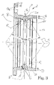
- FIG. 1 shows an overall view of a bearing ring according to the invention
- FIG. 2 shows the bearing ring according to FIG. 1 in a front view
- FIG. 3 shows the bearing ring according to FIG. 1 in a longitudinal section taken along the line II-II from FIG. 3 , and
- FIG. 4 shows a longitudinal section through a wheel bearing unit according to the invention which is fixed at least in terms of rotation on the vehicle.
- FIG. 5 shows a further exemplary embodiment of a bearing ring according to the invention in longitudinal section
- FIG. 6 shows the detail X of the bearing ring according to FIG. 5 in an enlarged illustration
- FIG. 7 shows the detail Y of the bearing ring according to FIG. 5 in an enlarged illustration.
- FIG. 4 shows a wheel bearing unit 1 with a bearing ring 2 according to the invention for a driven and steered vehicle wheel.
- the bearing ring and the wheel bearing unit according to the invention are also provided, alternatively to this, for nondriven and/or nonsteered wheels.
- the wheel bearing unit 1 further, has a flanged ring 3 , a supporting ring 4 , two rows of rolling bodies 5 in the form of balls, and seals 6 and 7 . Each of the rows of rolling bodies 5 is held and guided in each case by means of a cage 8 .
- the wheel bearing unit 1 is fixed in a bore 9 by means of the bearing ring 2 designed as an outer ring.
- the bearing ring 2 is pressed into the bore 9 and is radially contracted elastically to an extent such that the wheel bearing unit 1 is prestressed.
- the rolling bodies 5 are in this case supported toward one side, circumferentially on the inside of the bearing ring 2 , on raceways 10 and 11 and in the other direction on raceways 12 and 13 .
- the raceway 12 is formed on the supporting ring 4 .
- the raceway 13 is introduced into the flanged ring 3 .
- the raceways 11 and 12 or 10 and 13 are in each case arranged so as to be offset relative to one another in the direction of the axis of rotation 1 a of the wheel bearing unit 1 and are formed at least partially on a rim 2 a projecting radially out of the bearing ring 2 at least between the rows of rolling bodies 5 .
- the rows of rolling bodies 5 are arranged in what is known as an O-arrangement in relation to one another.
- the intersection points of the contact lines A with the axis of rotation 1 a of the respective rows are at an axial distance from one another.
- the pressure angle ⁇ is provided in a range of 20 to 45° ( FIG. 3 , FIG. 4 ).
- the pressure angle ⁇ is the angle which the connecting lines A between the two contact points B and C between the rolling bodies 5 and raceways 10 and 13 or 11 and 12 form with the imaginary radial plane R′′.
- the rolling bodies 5 are not supported in a punctiform manner on the respective raceway 10 , 11 , 12 or 13 , but fit snugly, at least under load, into a raceway 10 , 11 , 12 or 13 .
- the raceways 10 , 11 , 12 or 13 are therefore provided with a groove radius R which is only slightly greater than the ball radius K of the rolling bodies 5 .
- the [ratio], designated by specialists as “osculation”, of groove radius R to ball radius K amounts preferably, at the raceways 10 and 11 on the outer ring, in this case on the bearing ring 2 , to [1.055:1] and, on the inner raceways 12 and 13 , in this case on the supporting ring 3 or on the flanged ring 3 , to [1.035:1]. Consequently, in the event of osculation, the contact points B and C are the centerpoints of the contact or stand-on surfaces between rolling body and raceway, said centerpoints being pierced by the connecting lines A also known as “contact lines”.
- the flanged ring 3 is arranged rotatably about the axis of rotation 1 a with respect to the bearing ring 2 fixed to the vehicle and in this case takes up the supporting ring 4 .
- the supporting ring 4 is secured at least axially on the flanged ring 3 by means of a crimped rim 3 a of the flanged ring, said crimped rim bearing against the supporting ring 4 .
- the flanged ring 3 has projecting radially from it a connecting flange 3 b to which a brake disk and the rim of a vehicle wheel are conventionally fastened.
- the flanged ring 3 is driven and, for this purpose, has on its inner circumference a serration 14 , into which a driven drive element 15 , not described in any more detail here, engages positively.
- the bearing ring 2 is provided radially on the outside with an annular groove 16 (see also FIG. 3 ).
- the annular groove 16 adjoins the rim 2 a radially on the outside.
- the invention also provides refinements in which the annular groove 16 extends radially into the rim 2 a and even partially radially to between the rows of rolling bodies 5 .
- the bearing ring 2 is freely moveable elastically in the supporting directions identified by the run of the connecting lines A.
- the material of the bearing ring 2 is deformed elastically toward the annular groove 16 in the region of the raceways 10 and 11 under load, since, because of the annular groove 16 , the bearing ring 2 is not supported radially at this point in the receptacle of the bearing ring 2 . This is advantageous both during the elastic prestressing of the wheel bearing unit 1 upon installation and for the wheel bearing unit 1 when the vehicle is in operation, since overloads due to brief punctiform stress peaks in rolling contact are avoided.
- the annular groove 16 is formed on the bearing ring 2 by the bearing ring 2 being contracted in the direction of the axis of rotation with respect to the rim 2 a .
- the rim 2 a starting from the radially lowest point P ( FIG. 3 ) of the annular groove 16 , is radially thicker than the wall thickness of the initial material, the rim 2 a pointing, radially opposite of the flange 18 , inward in the direction of the axis of rotation 1 a .
- a cylindrical outer surface area 17 pointing in the radial direction is formed on the inner circumference of the rim 2 a .
- the rim 2 a is, on the flank side, a shoulder for each of the raceways 10 and 11 and projects radially out of the bearing ring 2 beyond the raceways in the direction of the axis of rotation.
- the wall thickness of the bearing ring 2 at the thickest point S, between the annular groove 16 and the respective raceway 10 or 11 is at least as great as the wall thickness of the initial material.
- the bearing ring 2 has a hollow-cylindrical portion 20 , the wall thickness of which is lower than the wall thickness of the initial material ( FIG. 3 ).
- a flange 18 produced in one part with the bearing ring 2 projects outward from the bearing ring 2 radially.
- the flange 18 has introduced into it ( FIGS. 1 and 2 ) passage holes 18 a which are uniformly spaced apart from one another circumferentially and through which in each case a bolt 19 passes, as illustrated in FIG. 4 .
- the bearing ring 2 is secured in the circumferential direction against micromovements and circumferentially and axially against creeping out of the bore 9 .
- the bolts 19 are fixed with respect to the surrounding structure of the wheel bearing unit 1 by means of a press fit or alternatively by means of threads.
- the flange 18 has the thickness H of the initial material.
- the thickness or wall thickness of the initial material is defined as a function of the blank used for producing the bearing and comes under the common term “thickness”. Sheet metals or tubes are provided as blanks. The term “thickness” is assigned to the sheet metal and the term “wall thickness” to the tube as initial material.
- FIG. 5 A further exemplary embodiment of a bearing ring 21 is illustrated in FIG. 5 .
- the bearing ring 21 is produced in one part with a flange 22 .
- the bearing ring 21 has the raceways 10 and 11 on its inner circumference.
- the raceways 10 and 11 are partially formed on a rim 23 .
- the rim 23 is thus provided on each of the two sides with a shoulder for the support of rolling bodies 5 .
- the rim 23 -projects radially inward in the direction of the axis of rotation 21 a and has a cylindrical outer surface area 23 a pointing toward the axis of rotation 21 a .
- An annular groove 26 adjoins the rim 23 radially on the outside.
- the bearing ring 21 merges axially on each of the two sides into a hollow-cylindrical portion 24 and 25 axially adjoining the raceway 10 and raceway 11 respectively.
- the radially greatest wall thicknesses t of the hollow-cylindrical portions 24 and 25 are lower than the smallest radial distance T between the radially lowest point P 1 in the annular groove 26 and the cylindrical outer surface area 23 a.
- the contact lines A running through the raceways 10 and 11 penetrate the plane R′′ running centrally through the annular groove axially and form the pressure angles ⁇ between themselves and the plane R′′.
- the lowest wall thickness T 1 , codirectional with the run of the contact lines A, of the rim 23 is greater in the region of the raceways 10 and 11 than the radially greatest wall thickness t of the hollow-cylindrical portions 24 and 25 .
- the contact lines A emerge outward from the bearing ring 23 in the annular groove 26 .
- the hollow-cylindrical portion 24 merges into the flange 22 via an edge rounding 27 ( FIG. 7 ).
- the edge rounding 27 runs out in an annular planar surface 28 .
- the planar surface 28 is peripherally delimited, radially on the outside, by a projection 29 projecting axially from the flange 23 .
- the projection 29 runs radially between the planar surface 28 and three flange holes 30 introduced in the flange 22 .
- the flange holes 30 are passage holes emanating from at least one further planar surface 31 . As illustrated in FIG. 6 , the planar surface 31 either lies on the same plane as the planar surface 28 or runs parallel to the latter in another plane.
- the passage holes are in each case provided with a chamfer 32 at the transition to the planar surface 31 .
Landscapes
- Engineering & Computer Science (AREA)
- General Engineering & Computer Science (AREA)
- Mechanical Engineering (AREA)
- Manufacturing & Machinery (AREA)
- Rolling Contact Bearings (AREA)
- Mounting Of Bearings Or Others (AREA)
Applications Claiming Priority (3)
| Application Number | Priority Date | Filing Date | Title |
|---|---|---|---|
| DE10331180.7 | 2003-07-10 | ||
| DE10331180A DE10331180A1 (de) | 2003-07-10 | 2003-07-10 | Lagerring und Radlagereinheit |
| PCT/DE2004/001465 WO2005008085A1 (de) | 2003-07-10 | 2004-07-08 | Lagerring und radlagereinheit |
Publications (2)
| Publication Number | Publication Date |
|---|---|
| US20060171624A1 US20060171624A1 (en) | 2006-08-03 |
| US7465102B2 true US7465102B2 (en) | 2008-12-16 |
Family
ID=34071607
Family Applications (1)
| Application Number | Title | Priority Date | Filing Date |
|---|---|---|---|
| US10/564,135 Expired - Fee Related US7465102B2 (en) | 2003-07-10 | 2004-07-08 | Bearing ring and wheel bearing unit |
Country Status (9)
| Country | Link |
|---|---|
| US (1) | US7465102B2 (de) |
| EP (1) | EP1644648B1 (de) |
| JP (1) | JP2006528326A (de) |
| KR (1) | KR20060032199A (de) |
| CN (1) | CN100545471C (de) |
| BR (1) | BRPI0412500A (de) |
| CA (1) | CA2534817A1 (de) |
| DE (1) | DE10331180A1 (de) |
| WO (1) | WO2005008085A1 (de) |
Cited By (3)
| Publication number | Priority date | Publication date | Assignee | Title |
|---|---|---|---|---|
| US20060117903A1 (en) * | 2004-10-13 | 2006-06-08 | Nsk Ltd. | Wheel support hub unit, bearing ring member for wheel support hub unit, and method of manufacturing the same |
| US20110254355A1 (en) * | 2010-04-20 | 2011-10-20 | Aktiebolaget Skf | Asymmetric Wheel Hub Assembly |
| CN112918185A (zh) * | 2019-12-06 | 2021-06-08 | 斯凯孚公司 | 包括轮毂轴承单元和悬架立柱或转向节的车辆用悬架组件 |
Families Citing this family (28)
| Publication number | Priority date | Publication date | Assignee | Title |
|---|---|---|---|---|
| ITTO20040875A1 (it) * | 2004-12-14 | 2005-03-14 | Skf Ab | Unita' cuscinetto per il mozzo della ruota di un autoveicolo. |
| EP1705391B1 (de) * | 2005-03-24 | 2008-05-14 | Aktiebolaget SKF | Radlagereinheit für ein Kraftfahrzeug |
| WO2007078616A2 (en) * | 2005-12-22 | 2007-07-12 | Timken Us Corporation | Tapered bearing and method for manufacturing |
| DE102006007580A1 (de) * | 2006-02-18 | 2007-09-06 | Schaeffler Kg | Rotierendes landwirtschaftliches Werkzeug mit Lageranordnung |
| JP2008074332A (ja) * | 2006-09-25 | 2008-04-03 | Jtekt Corp | 車輪用転がり軸受装置 |
| DE102006051644A1 (de) * | 2006-11-02 | 2008-05-08 | Schaeffler Kg | Radlagerung für Kraftfahrzeuge |
| WO2008056446A1 (en) * | 2006-11-07 | 2008-05-15 | Ntn Corporation | Bearing device for wheel |
| DE112007002599T5 (de) | 2006-11-07 | 2010-01-14 | Ntn Corp. | Radlagervorrichtung für ein Fahrzeug |
| JP4205752B2 (ja) * | 2006-11-07 | 2009-01-07 | Ntn株式会社 | 車輪用軸受装置 |
| US8944694B2 (en) * | 2007-03-07 | 2015-02-03 | Ntn Corporation | Bearing device for driving wheel, and its assembling method |
| US8753018B2 (en) * | 2007-03-09 | 2014-06-17 | Schaeffler Kg | Wheel end support bearing |
| WO2008129799A1 (ja) * | 2007-04-04 | 2008-10-30 | Ntn Corporation | 車輪用軸受およびこれを備えた車輪用軸受装置 |
| JP2008284919A (ja) * | 2007-05-15 | 2008-11-27 | Ntn Corp | 車輪用軸受装置、車輪用軸受装置の組立方法、アセンブリ体、およびアセンブリ体の組立方法 |
| JP5570687B2 (ja) * | 2007-06-01 | 2014-08-13 | Ntn株式会社 | 車輪用軸受装置 |
| DE102007050215A1 (de) | 2007-10-04 | 2009-04-09 | Schaeffler Kg | Radlagerung für Kraftfahrzeuge |
| CN102802965A (zh) * | 2009-05-18 | 2012-11-28 | Skf公司 | 车轮轴承单元及其制造方法 |
| IT1394904B1 (it) * | 2009-07-21 | 2012-07-20 | Skf Ab | Anello esterno di cuscinetto volvente |
| ITTO20100328A1 (it) * | 2010-04-20 | 2011-10-21 | Skf Ab | Gruppo mozzo ruota a due corone di corpi volventi |
| IT1399978B1 (it) | 2010-04-20 | 2013-05-09 | Skf Ab | Gruppo mozzo ruota a due corone di corpi volventi |
| IT1399977B1 (it) | 2010-04-20 | 2013-05-09 | Skf Ab | Gruppo mozzo ruota a due corone di corpi volventi |
| ITTO20100330A1 (it) * | 2010-04-20 | 2011-10-21 | Skf Ab | Gruppo mozzo ruota asimmetrico |
| EP2725245B1 (de) * | 2011-06-21 | 2016-04-27 | NSK Ltd. | Kugellagereinheit |
| US9550518B2 (en) * | 2013-12-31 | 2017-01-24 | Trw Automotive U.S. Llc | Electric power steering assembly |
| ITUA20162312A1 (it) * | 2016-04-05 | 2017-10-05 | Skf Ab | Gruppo cuscinetto-mozzo con mozzo-rotore. |
| CN106379111B (zh) * | 2016-11-15 | 2018-12-14 | 安徽江淮汽车集团股份有限公司 | 一种等速万向节与轮毂连接结构及汽车 |
| DE102019135117A1 (de) * | 2019-12-19 | 2021-06-24 | Hirschvogel Umformtechnik Gmbh | Fahrwerkbauteil, Anordnung von Fahrwerkbauteil und Lagerbauteil sowie Fahrzeug mit einer solchen Anordnung und Verfahren zu deren Herstellung |
| CN114590120A (zh) * | 2022-03-03 | 2022-06-07 | 吉林大学 | 一种集成制动器和轮毂电机的车轮总成 |
| DE102023132983A1 (de) * | 2023-11-27 | 2025-05-28 | Schaeffler Technologies AG & Co. KG | Wälzlageranordnung und Verfahren zum Betrieb einer Wälzlageranordnung |
Citations (11)
| Publication number | Priority date | Publication date | Assignee | Title |
|---|---|---|---|---|
| US2037982A (en) * | 1933-02-23 | 1936-04-21 | Gen Motors Corp | Bearing and bearing mounting |
| DE924924C (de) | 1944-08-05 | 1955-03-10 | Star Kugelhalter Ges M B H Deu | Verfahren zur Herstellung spanlos gefertigter Laufringe fuer mehrreihige Waelzlager |
| US3749416A (en) * | 1970-02-05 | 1973-07-31 | Skf Ind Trading & Dev | Wheel support for an engine propelled road vehicle |
| US3757883A (en) * | 1971-02-03 | 1973-09-11 | Skf Nv | Wheel support for an engine propelled road vehicle |
| DE2636903A1 (de) * | 1976-08-17 | 1978-02-23 | Wagner & Co | Zwei- bzw. dreiteiliges, ein- oder doppelreihiges selbsthaltendes kugellager aus stahl, bestehend aus spanlos verformten kugellager-laufringen |
| US5177869A (en) * | 1988-02-11 | 1993-01-12 | Skf Nova Ab | Double row angular contact ball bearings and a method for the manufacture thereof |
| JPH07317777A (ja) | 1994-05-20 | 1995-12-08 | Ntn Corp | ハブユニット軸受外輪およびその製造方法 |
| GB2298685A (en) | 1995-03-09 | 1996-09-11 | Skf Gmbh | Bearing arrangement |
| JPH09151950A (ja) | 1995-11-30 | 1997-06-10 | Ntn Corp | 自動車の車輪用軸受装置 |
| EP1031439A2 (de) | 1999-02-24 | 2000-08-30 | Skf Industrie S.P.A. | Lager für Radnabe eines Motorfahrzeuges und Befestigungsverfahren des Lagers in einer Motorfahrzeugaufhängung |
| JP2003025803A (ja) * | 2001-07-19 | 2003-01-29 | Koyo Seiko Co Ltd | 車軸用軸受装置 |
Family Cites Families (9)
| Publication number | Priority date | Publication date | Assignee | Title |
|---|---|---|---|---|
| FR1175133A (fr) * | 1957-05-15 | 1959-03-20 | Rene Prevost Et Cie Ets | Roulements simplifiés et démontables pour roues de patins à roulettes |
| DE7032767U (de) * | 1970-09-02 | 1970-11-19 | Star Kugelhalter Gmbh Dt | Lenkspindellager. |
| DE2556244B2 (de) * | 1975-12-13 | 1977-09-29 | Uni-Cardan Ag, 5204 Lohmar | Lagerungsanordnung einer ueber ein gleichlaufdrehgelenk antreibbaren radnabe |
| DE8702275U1 (de) * | 1987-02-14 | 1987-04-02 | Wagner GmbH & Co, Fahrzeugteilefabrik, 6400 Fulda | Doppelreihiges Kugellager |
| JPH0396717A (ja) * | 1989-09-11 | 1991-04-22 | Koyo Seiko Co Ltd | ラジアル玉軸受 |
| JP2850182B2 (ja) * | 1993-04-14 | 1999-01-27 | 光洋精工株式会社 | 斜接玉軸受 |
| JP3526323B2 (ja) * | 1994-05-20 | 2004-05-10 | Ntn株式会社 | ハブユニット軸受外輪の製造方法 |
| EP1314903B1 (de) * | 1997-01-17 | 2005-08-31 | Nsk Ltd | Lagereinheit für eine Fahrzeugradaufhängung |
| EP1329727A1 (de) * | 2001-10-18 | 2003-07-23 | Nsk Ltd | Sensor zur Bestimmung der Drehgeschwindigkeit |
-
2003
- 2003-07-10 DE DE10331180A patent/DE10331180A1/de not_active Ceased
-
2004
- 2004-07-08 JP JP2006522210A patent/JP2006528326A/ja active Pending
- 2004-07-08 CA CA002534817A patent/CA2534817A1/en not_active Abandoned
- 2004-07-08 EP EP04762354A patent/EP1644648B1/de not_active Expired - Lifetime
- 2004-07-08 US US10/564,135 patent/US7465102B2/en not_active Expired - Fee Related
- 2004-07-08 BR BRPI0412500-2A patent/BRPI0412500A/pt not_active Application Discontinuation
- 2004-07-08 WO PCT/DE2004/001465 patent/WO2005008085A1/de not_active Ceased
- 2004-07-08 KR KR1020067000621A patent/KR20060032199A/ko not_active Withdrawn
- 2004-07-08 CN CNB2004800197936A patent/CN100545471C/zh not_active Expired - Fee Related
Patent Citations (11)
| Publication number | Priority date | Publication date | Assignee | Title |
|---|---|---|---|---|
| US2037982A (en) * | 1933-02-23 | 1936-04-21 | Gen Motors Corp | Bearing and bearing mounting |
| DE924924C (de) | 1944-08-05 | 1955-03-10 | Star Kugelhalter Ges M B H Deu | Verfahren zur Herstellung spanlos gefertigter Laufringe fuer mehrreihige Waelzlager |
| US3749416A (en) * | 1970-02-05 | 1973-07-31 | Skf Ind Trading & Dev | Wheel support for an engine propelled road vehicle |
| US3757883A (en) * | 1971-02-03 | 1973-09-11 | Skf Nv | Wheel support for an engine propelled road vehicle |
| DE2636903A1 (de) * | 1976-08-17 | 1978-02-23 | Wagner & Co | Zwei- bzw. dreiteiliges, ein- oder doppelreihiges selbsthaltendes kugellager aus stahl, bestehend aus spanlos verformten kugellager-laufringen |
| US5177869A (en) * | 1988-02-11 | 1993-01-12 | Skf Nova Ab | Double row angular contact ball bearings and a method for the manufacture thereof |
| JPH07317777A (ja) | 1994-05-20 | 1995-12-08 | Ntn Corp | ハブユニット軸受外輪およびその製造方法 |
| GB2298685A (en) | 1995-03-09 | 1996-09-11 | Skf Gmbh | Bearing arrangement |
| JPH09151950A (ja) | 1995-11-30 | 1997-06-10 | Ntn Corp | 自動車の車輪用軸受装置 |
| EP1031439A2 (de) | 1999-02-24 | 2000-08-30 | Skf Industrie S.P.A. | Lager für Radnabe eines Motorfahrzeuges und Befestigungsverfahren des Lagers in einer Motorfahrzeugaufhängung |
| JP2003025803A (ja) * | 2001-07-19 | 2003-01-29 | Koyo Seiko Co Ltd | 車軸用軸受装置 |
Cited By (8)
| Publication number | Priority date | Publication date | Assignee | Title |
|---|---|---|---|---|
| US20060117903A1 (en) * | 2004-10-13 | 2006-06-08 | Nsk Ltd. | Wheel support hub unit, bearing ring member for wheel support hub unit, and method of manufacturing the same |
| US8402661B2 (en) * | 2004-10-13 | 2013-03-26 | Nsk Ltd. | Wheel support hub unit, bearing ring member for wheel support hub unit, and method of manufacturing the same |
| US8881405B2 (en) | 2004-10-13 | 2014-11-11 | Nsk Ltd. | Wheel support hub unit, bearing ring member for wheel support hub unit, and method of manufacturing the same |
| US20110254355A1 (en) * | 2010-04-20 | 2011-10-20 | Aktiebolaget Skf | Asymmetric Wheel Hub Assembly |
| US8770850B2 (en) * | 2010-04-20 | 2014-07-08 | Aktiebolaget Skf | Asymmetric wheel hub assembly |
| CN112918185A (zh) * | 2019-12-06 | 2021-06-08 | 斯凯孚公司 | 包括轮毂轴承单元和悬架立柱或转向节的车辆用悬架组件 |
| US20210170790A1 (en) * | 2019-12-06 | 2021-06-10 | Aktiebolaget Skf | Suspension unit for a vehicle |
| US11833854B2 (en) * | 2019-12-06 | 2023-12-05 | Aktiebolaget Skf | Suspension unit for a vehicle |
Also Published As
| Publication number | Publication date |
|---|---|
| JP2006528326A (ja) | 2006-12-14 |
| CA2534817A1 (en) | 2005-01-27 |
| US20060171624A1 (en) | 2006-08-03 |
| EP1644648B1 (de) | 2013-04-03 |
| DE10331180A1 (de) | 2005-02-24 |
| KR20060032199A (ko) | 2006-04-14 |
| EP1644648A1 (de) | 2006-04-12 |
| CN100545471C (zh) | 2009-09-30 |
| CN1856658A (zh) | 2006-11-01 |
| BRPI0412500A (pt) | 2006-09-19 |
| WO2005008085A1 (de) | 2005-01-27 |
Similar Documents
| Publication | Publication Date | Title |
|---|---|---|
| US7465102B2 (en) | Bearing ring and wheel bearing unit | |
| EP2599640B1 (de) | Lagereinheit und Verfahren zur Herstellung eines Lagerbahnringelementes für eine Lagereinheit | |
| US7942585B2 (en) | Wheel bearing apparatus for a vehicle | |
| EP2230097B1 (de) | Lagervorrichtung für ein Rad | |
| US7604416B2 (en) | Outer ring of a wheel bearing, and axial securing element for said outer ring | |
| US20100226604A1 (en) | Bearing device for a wheel | |
| US7311363B2 (en) | Bearing apparatus for a wheel of vehicle | |
| KR20070072548A (ko) | 허브 유닛과 구름 베어링장치 및 그 제조방법 및 구름베어링장치의 조립장치 및 그 조립방법 | |
| US20170368873A1 (en) | Wheel Bearing Device | |
| US20030063828A1 (en) | Thrust bearing and method of making same | |
| KR20000058164A (ko) | 차륜 허브 베어링과 자동차 현가 장치에 베어링을장착하기 위한 방법 | |
| JP3650746B2 (ja) | 車輪用軸受の固定構造及び車輪用軸受 | |
| EP1944518A1 (de) | Lagervorrichtung für rad | |
| KR102507430B1 (ko) | 허브 유닛 베어링 및 그 제조 방법, 그리고, 자동차 및 그 제조 방법 | |
| US7607837B2 (en) | Wheel bearing module in a wheel carrier | |
| US7600923B2 (en) | Wheel bearing in a wheel carrier | |
| EP1830084B1 (de) | Lagervorrichtung für fahrzeug | |
| US20070177836A1 (en) | Outer ring of a wheel bearing | |
| JP2012197043A (ja) | 車輪用軸受装置およびその製造方法 | |
| US10465744B2 (en) | Angular contact ball bearing having a cold-formed bearing ring, and a method for manufacturing a bearing ring of said angular contact ball bearing | |
| EP2975278A1 (de) | Wälzlager und Verfahren zur Herstellung eines solches Wälzlagers | |
| JP7004092B2 (ja) | かしめアセンブリおよびその製造方法、ハブユニット軸受およびその製造方法、並びに、自動車およびその製造方法 | |
| JP4844967B2 (ja) | 車輪用軸受装置 | |
| US20250290547A1 (en) | Rolling bearing with axial stops, in particular for a steering column | |
| JPH0536091Y2 (de) |
Legal Events
| Date | Code | Title | Description |
|---|---|---|---|
| AS | Assignment |
Owner name: INA-SCHAEFFLER KG, GERMANY Free format text: ASSIGNMENT OF ASSIGNORS INTEREST;ASSIGNORS:NIEBLING, PETER;HOFMANN, HEINRICH;DLUGAI, DARIUS;AND OTHERS;REEL/FRAME:017724/0632;SIGNING DATES FROM 20060127 TO 20060202 |
|
| AS | Assignment |
Owner name: SCHAEFFLER KG, GERMANY Free format text: ASSIGNMENT OF ASSIGNORS INTEREST;ASSIGNORS:NIEBLING, PETER;HOFMANN, HEINRICH;DLUGAI, DARIUS;AND OTHERS;REEL/FRAME:017453/0462;SIGNING DATES FROM 20060127 TO 20060227 |
|
| STCF | Information on status: patent grant |
Free format text: PATENTED CASE |
|
| FPAY | Fee payment |
Year of fee payment: 4 |
|
| AS | Assignment |
Owner name: SCHAEFFLER TECHNOLOGIES GMBH & CO. KG, GERMANY Free format text: ASSIGNMENT OF ASSIGNORS INTEREST;ASSIGNOR:SCHAEFFLER KG;REEL/FRAME:028523/0790 Effective date: 20100128 |
|
| AS | Assignment |
Owner name: SCHAEFFLER TECHNOLOGIES AG & CO. KG, GERMANY Free format text: CHANGE OF NAME;ASSIGNOR:SCHAEFFLER TECHNOLOGIES GMBH & CO. KG;REEL/FRAME:028533/0036 Effective date: 20120119 |
|
| AS | Assignment |
Owner name: SCHAEFFLER TECHNOLOGIES AG & CO. KG, GERMANY Free format text: CHANGE OF NAME;ASSIGNOR:SCHAEFFLER TECHNOLOGIES GMBH & CO. KG;REEL/FRAME:037732/0347 Effective date: 20150101 Owner name: SCHAEFFLER TECHNOLOGIES GMBH & CO. KG, GERMANY Free format text: MERGER AND CHANGE OF NAME;ASSIGNORS:SCHAEFFLER TECHNOLOGIES AG & CO. KG;SCHAEFFLER VERWALTUNGS 5 GMBH;REEL/FRAME:037732/0228 Effective date: 20131231 |
|
| FPAY | Fee payment |
Year of fee payment: 8 |
|
| AS | Assignment |
Owner name: SCHAEFFLER TECHNOLOGIES AG & CO. KG, GERMANY Free format text: CORRECTIVE ASSIGNMENT TO CORRECT THE PROPERTY NUMBERS PREVIOUSLY RECORDED ON REEL 037732 FRAME 0347. ASSIGNOR(S) HEREBY CONFIRMS THE APP. NO. 14/553248 SHOULD BE APP. NO. 14/553258;ASSIGNOR:SCHAEFFLER TECHNOLOGIES GMBH & CO. KG;REEL/FRAME:040404/0530 Effective date: 20150101 |
|
| FEPP | Fee payment procedure |
Free format text: MAINTENANCE FEE REMINDER MAILED (ORIGINAL EVENT CODE: REM.); ENTITY STATUS OF PATENT OWNER: LARGE ENTITY |
|
| LAPS | Lapse for failure to pay maintenance fees |
Free format text: PATENT EXPIRED FOR FAILURE TO PAY MAINTENANCE FEES (ORIGINAL EVENT CODE: EXP.); ENTITY STATUS OF PATENT OWNER: LARGE ENTITY |
|
| STCH | Information on status: patent discontinuation |
Free format text: PATENT EXPIRED DUE TO NONPAYMENT OF MAINTENANCE FEES UNDER 37 CFR 1.362 |
|
| FP | Lapsed due to failure to pay maintenance fee |
Effective date: 20201216 |