US7147602B2 - Blood rheology measuring apparatus - Google Patents
Blood rheology measuring apparatus Download PDFInfo
- Publication number
- US7147602B2 US7147602B2 US10/190,783 US19078302A US7147602B2 US 7147602 B2 US7147602 B2 US 7147602B2 US 19078302 A US19078302 A US 19078302A US 7147602 B2 US7147602 B2 US 7147602B2
- Authority
- US
- United States
- Prior art keywords
- blood
- measuring
- blood rheology
- rheology
- measuring apparatus
- Prior art date
- Legal status (The legal status is an assumption and is not a legal conclusion. Google has not performed a legal analysis and makes no representation as to the accuracy of the status listed.)
- Expired - Lifetime, expires
Links
- 239000008280 blood Substances 0.000 title claims abstract description 320
- 210000004369 blood Anatomy 0.000 title claims abstract description 320
- 238000000518 rheometry Methods 0.000 title claims abstract description 257
- 230000017531 blood circulation Effects 0.000 claims abstract description 120
- 230000010365 information processing Effects 0.000 claims abstract 5
- 238000012545 processing Methods 0.000 claims description 73
- 230000008859 change Effects 0.000 claims description 44
- 210000001015 abdomen Anatomy 0.000 claims description 24
- 230000002123 temporal effect Effects 0.000 claims description 23
- 230000000694 effects Effects 0.000 claims description 12
- 235000013305 food Nutrition 0.000 claims description 6
- 230000002093 peripheral effect Effects 0.000 claims description 4
- 229920001971 elastomer Polymers 0.000 claims description 2
- 230000003028 elevating effect Effects 0.000 claims 3
- 238000000034 method Methods 0.000 abstract description 72
- 210000001367 artery Anatomy 0.000 description 57
- 235000012054 meals Nutrition 0.000 description 46
- 230000036772 blood pressure Effects 0.000 description 45
- 210000004204 blood vessel Anatomy 0.000 description 30
- 239000000306 component Substances 0.000 description 23
- 238000012937 correction Methods 0.000 description 19
- 238000005259 measurement Methods 0.000 description 19
- 238000005070 sampling Methods 0.000 description 17
- 238000010586 diagram Methods 0.000 description 14
- XLYOFNOQVPJJNP-UHFFFAOYSA-N water Chemical compound O XLYOFNOQVPJJNP-UHFFFAOYSA-N 0.000 description 13
- 210000000707 wrist Anatomy 0.000 description 13
- WABPQHHGFIMREM-UHFFFAOYSA-N lead(0) Chemical compound [Pb] WABPQHHGFIMREM-UHFFFAOYSA-N 0.000 description 10
- 150000003839 salts Chemical class 0.000 description 10
- 239000000126 substance Substances 0.000 description 10
- 206010020772 Hypertension Diseases 0.000 description 9
- 230000036760 body temperature Effects 0.000 description 9
- 230000036541 health Effects 0.000 description 8
- 238000001228 spectrum Methods 0.000 description 7
- 238000007796 conventional method Methods 0.000 description 5
- 235000006694 eating habits Nutrition 0.000 description 5
- 230000008602 contraction Effects 0.000 description 4
- 230000002596 correlated effect Effects 0.000 description 4
- 230000001419 dependent effect Effects 0.000 description 4
- 238000003745 diagnosis Methods 0.000 description 4
- 229920002379 silicone rubber Polymers 0.000 description 4
- 239000004945 silicone rubber Substances 0.000 description 4
- LFQSCWFLJHTTHZ-UHFFFAOYSA-N Ethanol Chemical compound CCO LFQSCWFLJHTTHZ-UHFFFAOYSA-N 0.000 description 3
- 208000001953 Hypotension Diseases 0.000 description 3
- 239000004698 Polyethylene Substances 0.000 description 3
- 230000006806 disease prevention Effects 0.000 description 3
- 238000005516 engineering process Methods 0.000 description 3
- 208000012866 low blood pressure Diseases 0.000 description 3
- -1 polyethylene Polymers 0.000 description 3
- 229920000573 polyethylene Polymers 0.000 description 3
- XUIMIQQOPSSXEZ-UHFFFAOYSA-N Silicon Chemical compound [Si] XUIMIQQOPSSXEZ-UHFFFAOYSA-N 0.000 description 2
- 230000009471 action Effects 0.000 description 2
- 238000004458 analytical method Methods 0.000 description 2
- 208000011775 arteriosclerosis disease Diseases 0.000 description 2
- 230000015572 biosynthetic process Effects 0.000 description 2
- 238000004364 calculation method Methods 0.000 description 2
- 201000010099 disease Diseases 0.000 description 2
- 208000037265 diseases, disorders, signs and symptoms Diseases 0.000 description 2
- 239000012153 distilled water Substances 0.000 description 2
- 239000003814 drug Substances 0.000 description 2
- 239000000463 material Substances 0.000 description 2
- 230000010349 pulsation Effects 0.000 description 2
- 238000005086 pumping Methods 0.000 description 2
- 230000035945 sensitivity Effects 0.000 description 2
- 229910052710 silicon Inorganic materials 0.000 description 2
- 239000010703 silicon Substances 0.000 description 2
- 230000004622 sleep time Effects 0.000 description 2
- 239000000243 solution Substances 0.000 description 2
- 238000003860 storage Methods 0.000 description 2
- 238000012360 testing method Methods 0.000 description 2
- 230000009466 transformation Effects 0.000 description 2
- 210000003462 vein Anatomy 0.000 description 2
- 206010005746 Blood pressure fluctuation Diseases 0.000 description 1
- 229920000742 Cotton Polymers 0.000 description 1
- 208000010201 Exanthema Diseases 0.000 description 1
- 235000010469 Glycine max Nutrition 0.000 description 1
- 244000068988 Glycine max Species 0.000 description 1
- HTTJABKRGRZYRN-UHFFFAOYSA-N Heparin Chemical compound OC1C(NC(=O)C)C(O)OC(COS(O)(=O)=O)C1OC1C(OS(O)(=O)=O)C(O)C(OC2C(C(OS(O)(=O)=O)C(OC3C(C(O)C(O)C(O3)C(O)=O)OS(O)(=O)=O)C(CO)O2)NS(O)(=O)=O)C(C(O)=O)O1 HTTJABKRGRZYRN-UHFFFAOYSA-N 0.000 description 1
- 206010061216 Infarction Diseases 0.000 description 1
- 208000010340 Sleep Deprivation Diseases 0.000 description 1
- 239000003146 anticoagulant agent Substances 0.000 description 1
- 229940127219 anticoagulant drug Drugs 0.000 description 1
- 230000006399 behavior Effects 0.000 description 1
- 235000021028 berry Nutrition 0.000 description 1
- 238000010241 blood sampling Methods 0.000 description 1
- 210000000988 bone and bone Anatomy 0.000 description 1
- 239000000919 ceramic Substances 0.000 description 1
- 238000004140 cleaning Methods 0.000 description 1
- 238000004891 communication Methods 0.000 description 1
- 238000010276 construction Methods 0.000 description 1
- 239000003599 detergent Substances 0.000 description 1
- 238000009826 distribution Methods 0.000 description 1
- 235000005686 eating Nutrition 0.000 description 1
- 201000005884 exanthem Diseases 0.000 description 1
- 235000012041 food component Nutrition 0.000 description 1
- 239000005428 food component Substances 0.000 description 1
- 229960002897 heparin Drugs 0.000 description 1
- 229920000669 heparin Polymers 0.000 description 1
- 230000006872 improvement Effects 0.000 description 1
- 238000001727 in vivo Methods 0.000 description 1
- 238000012623 in vivo measurement Methods 0.000 description 1
- 230000007574 infarction Effects 0.000 description 1
- 238000002347 injection Methods 0.000 description 1
- 239000007924 injection Substances 0.000 description 1
- 238000011835 investigation Methods 0.000 description 1
- 239000007788 liquid Substances 0.000 description 1
- 210000002751 lymph Anatomy 0.000 description 1
- 239000000203 mixture Substances 0.000 description 1
- 210000003205 muscle Anatomy 0.000 description 1
- 230000007935 neutral effect Effects 0.000 description 1
- 206010037844 rash Diseases 0.000 description 1
- 238000011160 research Methods 0.000 description 1
- 239000008400 supply water Substances 0.000 description 1
- 235000015193 tomato juice Nutrition 0.000 description 1
- 238000012546 transfer Methods 0.000 description 1
- 238000004506 ultrasonic cleaning Methods 0.000 description 1
- 235000015192 vegetable juice Nutrition 0.000 description 1
- 235000021419 vinegar Nutrition 0.000 description 1
- 239000000052 vinegar Substances 0.000 description 1
Images


Classifications
-
- A—HUMAN NECESSITIES
- A61—MEDICAL OR VETERINARY SCIENCE; HYGIENE
- A61B—DIAGNOSIS; SURGERY; IDENTIFICATION
- A61B5/00—Measuring for diagnostic purposes; Identification of persons
- A61B5/02—Detecting, measuring or recording for evaluating the cardiovascular system, e.g. pulse, heart rate, blood pressure or blood flow
- A61B5/021—Measuring pressure in heart or blood vessels
- A61B5/022—Measuring pressure in heart or blood vessels by applying pressure to close blood vessels, e.g. against the skin; Ophthalmodynamometers
-
- A—HUMAN NECESSITIES
- A61—MEDICAL OR VETERINARY SCIENCE; HYGIENE
- A61B—DIAGNOSIS; SURGERY; IDENTIFICATION
- A61B5/00—Measuring for diagnostic purposes; Identification of persons
- A61B5/68—Arrangements of detecting, measuring or recording means, e.g. sensors, in relation to patient
- A61B5/6801—Arrangements of detecting, measuring or recording means, e.g. sensors, in relation to patient specially adapted to be attached to or worn on the body surface
- A61B5/6802—Sensor mounted on worn items
- A61B5/681—Wristwatch-type devices
-
- A—HUMAN NECESSITIES
- A61—MEDICAL OR VETERINARY SCIENCE; HYGIENE
- A61B—DIAGNOSIS; SURGERY; IDENTIFICATION
- A61B5/00—Measuring for diagnostic purposes; Identification of persons
- A61B5/68—Arrangements of detecting, measuring or recording means, e.g. sensors, in relation to patient
- A61B5/6801—Arrangements of detecting, measuring or recording means, e.g. sensors, in relation to patient specially adapted to be attached to or worn on the body surface
- A61B5/6813—Specially adapted to be attached to a specific body part
- A61B5/6825—Hand
- A61B5/6826—Finger
-
- A—HUMAN NECESSITIES
- A61—MEDICAL OR VETERINARY SCIENCE; HYGIENE
- A61B—DIAGNOSIS; SURGERY; IDENTIFICATION
- A61B5/00—Measuring for diagnostic purposes; Identification of persons
- A61B5/68—Arrangements of detecting, measuring or recording means, e.g. sensors, in relation to patient
- A61B5/6801—Arrangements of detecting, measuring or recording means, e.g. sensors, in relation to patient specially adapted to be attached to or worn on the body surface
- A61B5/683—Means for maintaining contact with the body
- A61B5/6838—Clamps or clips
-
- A—HUMAN NECESSITIES
- A61—MEDICAL OR VETERINARY SCIENCE; HYGIENE
- A61B—DIAGNOSIS; SURGERY; IDENTIFICATION
- A61B8/00—Diagnosis using ultrasonic, sonic or infrasonic waves
- A61B8/06—Measuring blood flow
-
- A—HUMAN NECESSITIES
- A61—MEDICAL OR VETERINARY SCIENCE; HYGIENE
- A61B—DIAGNOSIS; SURGERY; IDENTIFICATION
- A61B5/00—Measuring for diagnostic purposes; Identification of persons
- A61B5/72—Signal processing specially adapted for physiological signals or for diagnostic purposes
- A61B5/7235—Details of waveform analysis
- A61B5/7253—Details of waveform analysis characterised by using transforms
- A61B5/7257—Details of waveform analysis characterised by using transforms using Fourier transforms
Definitions
- the present invention relates to a blood rheology measuring apparatus indicating a flowability referred to generally as a fluent/viscous degree of blood, particularly to a technology of measuring an amount of a blood flow flowing in the artery, discerning a very small circulating blood flow rate constituting a basis of activity of the human texture and carrying out assessment of health, diagnosis of disease, assessment of effect of medicine and the like.
- the elbow of the subject is disinfected by alcohol cotton and blood is sampled from the elbow vein by using a vacuum blood sampling tube in which there is put a heparin solution to constitute a quantity of 5% as an anticoagulant by using a 1 ml disposable syringe and a 23G disposable needle before sampling blood.
- micro-channels of a capillary model fabricated by a silicon chip (micro-channel array silicon chip), which are aligned in parallel with each other by 8736 pieces with a size of a width of 7 ⁇ m, a length of 30 ⁇ m and a depth of 4.5 ⁇ m, subjected to ultrasonic cleaning in a pertinent amount of mixture solution of distilled water, ethanol and a liquid neutral detergent (trade name: malemon) (aiming 1:1:0.3) and sets to a blood rheology measuring apparatus (MC-FAN). Further, after cleaning a cylinder for a sample in the apparatus by distilled water, physiological salt water is substituted therefor and micro-channel array pass time period is measured by a difference of 20 cmAq by using 100 ⁇ l of the physiological salt water.
- blood is measured.
- 200 through 300 ⁇ l of a blood sample is sampled by using the 1 ml disposable syringe attached with the 23G disposable needle and further attached with about 10 cm of a polyethylene tube at a needle tip thereof, a tip of the polyethylene tube is put to the bottom of the cylinder and the blood sample is injected to push up the remaining physiological salt water.
- the blood sample is controlled to constitute 100 ⁇ l while extracting blood from an upper end opening portion of the cylinder by using the polyethylene tube and a micro-channel array pass time period of 100 ⁇ l of blood is measured by a difference of 20 cmAq. similar to the case of the physiological salt water.
- the pass time period of the sampled blood is corrected by the pass time period of the physiological salt water and the time period is defined as a total blood pass time period to constitute an index of blood rheology.
- the total blood pass time period is short, blood rheology is low and therefore, the blood flows in the capillary tube without resistance. That is, there is increased the very small circulating blood flow amount constituting the basis of activity of the human texture and therefore, the total blood pass time period can certify the healthy body.
- a blood rheology measuring apparatus is on the basis of a constitution comprising means for noninvasively detecting a flow velocity of the blood flowing in the blood vessel as a Doppler shift signal by transmitting and receiving a wave from a face of the skin and means for analyzing blood rheology from a temporal change of a value of the flow velocity of the blood detected by the means and the apparatus is small-sized, portable and capable of simply measuring blood rheology at any time at anywhere even at outside of a medical institution without applying burden on a subject.
- a blood rheology measuring apparatus comprising a measuring portion for measuring information with regard to blood circulation at inside of a living body from a surface of the living body, and a signal processing portion for processing a signal detected from the measuring portion, wherein information with regard to a blood rheology is provided as a result of processing the signal.
- the measuring portion and the signal processing portion are integrally or separately made portable to thereby enable to provide the information with regard to the blood rheology continuously or daily.
- the information with regard to the blood circulation to be measured in the measuring portion is a change in a blood flow velocity based on a Doppler effect by a blood flow.
- the measuring portion is an ultrasonic wave sensor for transmitting and receiving an ultrasonic wave.
- the measuring portion is constructed by a constitution constituting a sensor for detecting information with regard to a pulse wave or a constitution having an input device for inputting individual information of gender or the like of a person to be measured for correcting measured data.
- inputting means for inputting daily eating habit information of the person to be measured and there is provided determining means for determining whether the eating habit of the person to be measured is suitable for the person to be measured from the information with regard to the blood rheology to thereby enable to inform a result of determination by the determining means to the person to be measured.
- a constitution having a temperature measuring portion brought into contact with a surface of the living body for measuring temperature of inside or the surface of the living body at a vicinity of the measuring portion or the measuring portion generates heat in measuring to thereby elevate a temperature of the measuring portion.
- the measuring portion is constructed by a constitution held by a holding portion capable of holding the measuring portion by bringing the measuring portion in to contact with the surface of the living body or a constitution in which the measuring portion and the temperature measuring portion are blocked from outside air, or the holding portion is constituted by a member having insulating performance or a member having elasticity such as rubber. Further, a shape of the holding portion is constituted by a shape of a finger ring or a shape of a mouse.
- a constitution utilizing a maximum blood flow velocity for one pulse (2) a constitution dividing the maximum blood flow velocity for one pulse by an integrated value of a pulse velocity, (3) a constitution for providing a Doppler shift intensity waveform reflected and returned from blood flow, calculating an intensity of each of frequency components of the Doppler shift signal (histogram), extracting a maximum frequency in a signal at an intensity level equal to or larger than a threshold in the histogram or a maximum frequency when an integrated value from a lower frequency component reaches a predetermined rate of a total thereof in the histogram, providing a waveform of a temporal change of the extracted frequency (frequency waveform) and analyzing blood rheology based on the maximum frequency in the frequency waveform, or (4) a constitution for analyzing blood rheology by an area value of a portion at and above a line connecting a minimum value of a one pulse waveform and a
- the means for noninvasively detecting the flow velocity of the blood flowing in the blood vessel includes a constitution of adopting an ultrasonic wave transmitter and receiver for transmitting and receiving an ultrasonic wave to and from the artery of the finger portion, or a constitution for adopting an ultrasonic wave transmitter and receiver for transmitting and receiving an ultrasonic wave to and from the artery at the finger tip portion.
- a blood rheology measuring apparatus including a compensating function by providing (1) means for operating and compensating for an amount of a change in the flow velocity of the blood based on expansion and construction of the blood vessel by a temperature value detected by means for detecting temperature of the blood vessel portion for detecting the blood flow and comprising (2) means for operating and compensating for an amount of a change based on blood pressure by dividing by a blood pressure value detected by blood pressure measuring means.
- FIG. 1 is a diagram for explaining a first blood rheology analyzing method according to the invention
- FIG. 2 is a diagram showing a Doppler shift intensity waveform of a signal received by an ultrasonic receiver according to the invention
- FIG. 3 is a graph showing a relationship between an FFT number in subjecting the Doppler shift intensity signal to high-velocity Fourier transformation and a pulse maximum sensitivity;
- FIG. 4 is a diagram showing a frequency waveform according to the invention extracted from the Doppler shift intensity signal
- FIG. 5A is a diagram for explaining a second blood rheology analyzing method according to the invention extracted from a frequency waveform and FIG. 5B is a diagram for explaining a third blood rheology analyzing method according to the invention;
- FIGS. 6A and 6B are explanatory views of Embodiment 1 (Embodiment 2) according to the invention in which FIG. 6A shows a finger ring type blood rheology measuring apparatus mounted to the finger and FIG. 6B illustrates a section taken along a line A–A′ of FIG. 6A ;
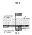
- FIG. 7 is an explanatory view of Embodiment 1 according to the invention and is a perspective sectional view of inside of a finger ring viewing from a B direction shown in FIG. 6B ;
- FIG. 8 is a block diagram showing an inner constitution of a signal processing portion of a blood rheology measuring apparatus of Embodiment 1 (Embodiments 3, 4, 5) and a state of connecting the signal processing portion and an ultrasonic sensor portion at inside of a finger ring portion;
- FIG. 9 is an explanatory view of Embodiment 2 according to the invention and is a perspective sectional view of inside of a finger ring viewing from the B direction shown in FIG. 6B ;
- FIG. 10 is a block diagram showing an inner constitution of a signal processing portion of a blood rheology measuring apparatus of Embodiment 2 (Embodiments 4, 5, 6) and a state of connecting the signal processing portion, an ultrasonic sensor portion at inside of a finger ring portion and a temperature sensor;
- FIG. 11 is a view showing an outlook constitution of a blood rheology measuring apparatus constituting Embodiment 3 (Embodiment 4);
- FIG. 12 illustrates a section taken along a line A–A′ of FIG. 11 with respect to Embodiment 3;
- FIG. 13 illustrates a section taken along a line B–B′ of FIG. 11 with respect to Embodiment 3;
- FIG. 14 is a view showing a sectional view of a mouse type blood rheology measuring apparatus of Embodiment 4, illustrating a section taken along a line A–A′ of FIG. 11 ;
- FIG. 15A is an outlook view of a wrist watch type blood rheology measuring apparatus constituting a fifth embodiment of the invention and FIG. 5B is a view showing a measuring state of the wrist watch type blood rheology measuring apparatus;
- FIG. 16 illustrates a section taken along a line A–A′ of FIG. 15B of the wrist watch type blood rheology measuring apparatus constituting the fifth embodiment
- FIG. 17 is a constitution view of an outlook of a finger sack type blood rheology measuring apparatus of a blood rheology measuring apparatus constituting a sixth embodiment of the invention.
- FIG. 18 illustrates a section taken along a line A–A′ of FIG. 17 according to the sixth embodiment of the invention.
- FIGS. 19A and 19B indicate data of a seventh embodiment of the invention by graphs
- FIGS. 20A and 20B indicate data of an eighth embodiment of the invention by graphs
- FIGS. 21A and 21B indicate data of a ninth embodiment of the invention by graphs
- FIG. 22 illustrates a tenth embodiment of the invention
- FIG. 23 illustrates the tenth embodiment of the invention
- FIG. 24 illustrates an eleventh embodiment of the invention
- FIG. 25 illustrates a twelfth embodiment of the invention
- FIG. 26 illustrates a thirteenth embodiment of the invention
- FIG. 27 illustrates a fourteenth embodiment of the invention.
- FIG. 28 illustrates a fifteenth embodiment of the invention.
- the blood rheology that is, the flowability of blood is brought into a close relationship with a viscosity of blood and when a change in a blood flow velocity is large, it can be regarded that there is brought about a state of low viscosity of blood.
- the viscosity is measured by the time period by which a predetermined amount of blood passes through the micro-channel array by a predetermined water column pressure difference and the time period is compared with that of the physiological salt water constituting a reference, which basically constitutes measurement of the viscosity.
- the measurement principle of the blood rheology measuring apparatus is based on the knowledge that there is a correlation between a form of a temporal change of a blood flow velocity appearing in pulsing with rheology of blood for calculating blood rheology from a change in the blood flow velocity appearing in pulsation.
- the blood rheology measuring apparatus of the invention comprises means for noninvasively detecting the flow velocity of blood flowing in the blood vessel as a Doppler shift signal by transmitting and receiving a wave to and from the skin face and means for analyzing a blood rheology from a change over time of a value of the blood flow velocity detected by the means as its basic constitution.
- a wave signal having a constant frequency radiated from the skin face to inside of the body is returned by being reflected by a substance in the body.
- the flow velocity of blood flowing in the blood vessel included therein is detected and a reflecting substance is not specified to the blood flow in the blood vessel.
- the blood flow in the blood vessel is moved with a velocity component and therefore, according to a reflected wave thereof, a frequency of wave is shifted by the Doppler's effect, however, in the case of a stationary substance which is not provided with a velocity component, such as bone or the blood vessel, the wave is reflected and returned to stay with the constant frequency.
- a component the same as that of the frequency on a transmitting side is reflected from a stationary substance and therefore, the component can easily be removed.
- a physical amount intended to detect in the invention is a flow velocity of blood in the blood vessel to which attention is paid and generally a signal having the highest level as the frequency component corresponds to an average flow velocity of flow of blood in the blood vessel and therefore, the component is extracted.
- the technology of the conventional ultrasonic blood flow meter is applicable as it is.
- ultrasonic wave is generally used for a wave used in detecting the blood flow velocity
- other wave of laser or the like can also be used.
- a pulse waveform is one of indexes indicating a blood circulating dynamic state and it seems that by measuring a rise velocity of the pulse waveform or measuring a velocity of changing a diameter of the blood vessel, a correlation thereof with blood rheology can be obtained.
- FIG. 1 shows a graph of a temporal change of a blood flow velocity in accordance with pulsing.
- the ratio Vn is calculated by dividing the maximum blood flow velocity Vx by an integrated value of the pulse velocity waveform (an integrated value of the pulse velocity waveform in one period of pulse: a pattern portion in the drawing).
- Vn C ⁇ Vx/ (integrated value of pulse velocity waveform) (1) where notation C designates a correction coefficient.
- the apparatus of the invention carries out an in-vivo measurement, the measured blood flow velocity is not only dependent on blood rheology but also dependent on conditions such as thickness and wall quality of the blood vessel and blood pressure and therefore, although the blood flow velocity information can relatively measure blood rheology, the blood flow velocity information cannot absolutely measure blood rheology.
- an ultrasonic sensor paired with an ultrasonic wave incident portion and an ultrasonic wave detecting portion to be opposed to the artery disposed proximately to the surface of the body and an ultrasonic wave is radiated toward the artery by exciting an ultrasonic wave transmitter of the ultrasonic wave incident portion by a constant frequency of about 9.6 MHz.
- the ultrasonic wave detecting portion receives an ultrasonic wave signal reflected to return by inside of the body.
- the received signal includes ultrasonic waves reflected by various portions at inside of the body, when a reflecting substance is stationary, a frequency of a reflected wave remains unchanged from the frequency of the incident wave and when the reflecting substance is a moving substance, the reflected wave is reflected by undergoing a frequency shift (Doppler shift) in accordance with a moving amount thereof.
- An intensity of the Doppler shift is extracted from the received signal to acquire a temporal procedure thereof.
- a waveform diagram of FIG. 2 indicates the temporal procedure and the temporal procedure is referred to as a Doppler shift intensity waveform.
- the Doppler shift intensity waveform is measured by using a sampling rate equal to or larger than 1/5000 of the frequency of the input waveform.
- the Doppler shift intensity waveform when the Doppler shift intensity waveform is calculated, in the case of the input waveform frequency of 9.6 MHz, the sampling rate is made to be equal to or larger than 1.92 kHz. The reason is that when the sampling rate is less than 1.92 kHz, the frequency waveform cannot be reproduced from the Doppler shift intensity waveform.
- the Doppler shift intensity waveform sampled at 1.92 KHz or higher can measure a frequency component of an intensity change of the Doppler shift intensity equal to or lower than 0.96 kHz at minimum.
- the frequency waveform is calculated from the frequency component, rheology of a viscous can be calculated.
- FFT high-speed Fourier transformation
- a relationship between the sampling rate for calculating the Doppler shift intensity wave form and a number of sampling data used in carrying out FFT is brought into a close relationship with a pulse number of a person to be measured, for example, in considering a case of measuring a person pulsing at 60 pulses, when there is used a sampling frequency (1.92 kHz) constituting a limit capable of reproducing the Doppler intensity waveform, the frequency waveform in accordance with pulsing cannot be provided unless the number of FFT is made to be equal to or less than 1000.
- FIG. 3 is a graph showing the relationship. It has been confirmed that when the number of FFT is made to be about 256, the number is almost made regardless of increasing pulsation or increasing the sampling rate and therefore, generally, the number of FFT is made to be about 256.
- the procedure is as follows.
- FIG. 4 shows a frequency waveform provided thereby.
- the frequency waveform is formed with 10000 as the threshold.
- the waveform is similar to the pulse waveform provided from blood flow velocity information (refer to FIG. 1 ).
- the method is a method tried in view of the fact that the threshold designating method is liable to be effected by influence of high frequency noise and a high frequency region is abandoned to remove the high frequency noise.
- the frequency waveform is formed with 80% (0.8) as the rate set value.
- the frequency waveform by the method is difficult to be effected by influence of high frequency noise, on the other hand, the method is inferior to the threshold designating method in view of accuracy and therefore, the threshold designating method may be adopted by dealing with the high frequency noise by preventing unrealistic high frequency components from being picked up.
- a maximum frequency is specified in the provided frequency waveform and rheology is calculated by using the maximum frequency.
- the method is based on a prediction that when blood is fluent, blood flow is easy to flow and the maximum blood flow velocity is increased.
- there is calculated an average of maximum frequency values of about three pulses as shown by FIG. 4 , there is a case in which the frequency waveform includes low frequency components and maximum frequencies at respective pulses vary.
- sampling may be carried out at a long period of pulsing.
- a pulse waveform of one pulse is sampled from a frequency waveform and an area value thereof is calculated to thereby calculate rheology.
- the method is based on a prediction that when blood is fluent, even at timings at which delivery pressure by pumping action of the heart is not applied, blood is predicted to flow as it is by inertia force and therefore, an integrated value of one pulse will be increased.
- information at low flow velocity near to 0 includes not few other velocity information of the vein or the like and therefore, according to the invention, as shown by FIG. 5B , there is calculated an area of a portion at and above a line connecting a minimum value of a waveform of one pulse and a minimum value of a waveform of successive pulse.
- Measurement of blood rheology is based on information of blood flow at inside of the actual blood vessel in the body and therefore, the detected blood flow signal is varied by being effected with influence of expansion or contraction of the blood vessel based on body temperature or influence of blood pressure. That is, when the body temperature rises, the blood vessel is expanded to be thick, blood becomes easy to flow, blood flow velocity is increased, however, this is a factor irrelevant to blood rheology. Further, a variation in the blood pressure value corresponds to a change in pump pressure operated to a flow path and the flow velocity (blood flow velocity) is varied in accordance therewith. This is also a variation in blood flow based on a factor irrelevant to blood rheology. Hence, according to the invention, there is adopted a constitution in which these values are separately detected and amounts of variation based thereon are compensated for.
- FIGS. 6A and 6B are views showing an outlook constitution of the embodiment of the blood rheology measuring apparatus used in the embodiment.
- the blood rheology measuring apparatus is constituted by being classified in two of a finger ring portion 1 and a signal processing portion 2 .
- FIG. 6B illustrates a section taken along a line A–A′ of FIG.
- an ultrasonic wave sensor portion 3 is present on an inner side of the finger ring portion 1 .
- FIG. 7 shows a sectional view of inside of the finger ring viewed from a B direction shown in FIG. 6B .
- an ultrasonic wave incident portion 31 and an ultrasonic wave detecting portion 32 are attached at a belly portion of the finger 6 .
- the arteries 5 disposed in the finger 6 are extended to the finger tip by passing both sides of the belly portion of the finger 6 and therefore, in order to measure flow of blood of the artery, the ultrasonic wave incident portion 31 and the ultrasonic wave detecting portion 32 are attached to a portion of the finger 6 shifted to the left of the center of the belly as shown by FIG. 6B such that an ultrasonic wave can be incident to aim at the artery.
- the portions 31 and 32 are attached to shift to the left, even when the portions 31 and 32 are attached to shift to the right to aim at the artery on the right side, the effect stays the same.
- the blood rheology measuring apparatus of Embodiment 1 is normally portable by mounting the finger ring portion 1 on the finger 6 and mounting the signal processing portion 2 on the arm. Further, also the signal processing portion 2 may be mounted on the finger 6 similar to the finger ring portion 1 .
- the signal processing portion 2 and the ultrasonic wave incident portion 31 and the ultrasonic wave detecting portion 32 installed at the finger ring portion 1 are connected by lead wires, a driving voltage signal is inputted from the signal processing portion 2 to the ultrasonic wave incident portion 31 via the lead wire and at the ultrasonic wave detecting portion 32 , a measured voltage signal is inputted to the signal processing portion 2 .
- FIG. 8 shows a block diagram showing an inner constitution of the signal processing portion 2 of the blood rheology measuring apparatus according to Embodiment 1 and a state of connecting the signal processing portion 2 and the ultrasonic wave sensor portion 3 at inside of the finger ring portion 1 .
- the signal processing portion 2 is generally constituted by a drive portion 21 , a receive portion 22 , a signal operating portion 23 and an output portion 24 .
- the drive portion 21 of Embodiment 1 oscillates PZT installed at the ultrasonic incident portion 31 and transmits drive voltage for making an ultrasonic wave incident on the artery 5 .
- the receive portion 22 receives voltage generated when PZT installed at the ultrasonic wave detecting portion 32 receives the ultrasonic wave.
- the signal operating portion 23 carries out various processings with regard to measurement of blood rheology by executing processing programs stored to a storage region (illustration is omitted) provided at inside thereof and outputs a result of the processings to the output portion 24 . Further, the signal operating portion 23 calculates the Doppler effect of blood flow by comparing a frequency of the ultrasonic wave emitted from the ultrasonic wave incident portion 31 and a frequency of the ultrasonic wave received by the ultrasonic wave detecting portion 32 . Further, the signal operating portion 23 calculates a flow velocity of blood flowing in the artery 6 by a change in the frequency and calculates a temporal change of the velocity.
- FIG. 1 shows the graph of the temporal change of the blood flow velocity accompanied by pulsing.
- the maximum blood flow velocity Vx is pointed out.
- the maximum blood flow velocity Vx is corrected to be V 1 by using a correction coefficient C 1 .
- V 1 C 1 ⁇ Vx
- the blood rheology measuring method of the invention is applied to a person having blood rheology in which the total blood pass time period calculated by using the maximum blood flow velocity Vx and the micro-channel array is 60 sec to thereby calculate the pulse velocity waveform and the correction coefficient C 1 is calculated such that V 1 becomes 60, in the case in which the total blood pass time period of the same person is changed to 35 sec, when V 1 is calculated from Equation 1 by using C 1 calculated above, V 1 shows a value of 35.
- the blood rheology measuring method of the embodiment is applied to a person having blood rheology in which the total blood pass time period calculated by using the micro-channel array according to the conventional method is 60 sec to thereby calculate the pulse velocity waveform and the correction coefficient C is calculated such that Vn of Equation 1 becomes 60, when the total pass time period of the same person is changed to 35 sec, when Vn is calculated from Equation 1 by using C calculated above, there is shown a value of 35 with an error of ⁇ 8%.
- V 1 and Vn can be found to be correlated with blood rheology and therefore, the analysis may be carried out by either of the methods.
- Embodiment 2 of the invention there is provided body temperature compensating means to above Embodiment 1.
- a mode of putting the blood rheology measuring apparatus on the finger is similar to that of FIG. 6 .
- FIG. 9 shows a perspective sectional view of the finger ring portion 1 viewing from the B direction of FIG. 6B .
- the blood rheology measuring apparatus of Embodiment 2 is constituted by being classified in two of the finger ring portion 1 and the signal processing portion 2 similar to Embodiment 1 and as shown by FIG. 9 , there are present the ultrasonic wave sensor portion 3 and a temperature sensor 7 on the inner side of the finger ring portion 1 .
- the temperature sensor 7 is attached to the portion of the finger 6 shifted to the left of the center of the belly in order to measure temperature at a vicinity of the artery 5 similar to the ultrasonic sensor portion. Thereby, reflection from the artery can firmly be caught and accuracy of measuring blood flow is promoted.
- the portions are attached to shift to the left, even when the portions are attached to shift to the right to aim at the artery on the right side, the effect stays the same.
- the blood rheology measuring apparatus of Embodiment 2 is normally portable by mounting the finger ring portion 1 to the finger 6 and mounting the signal processing portion 2 to the arm. Further, also the signal processing portion 2 may be mounted to the finger 6 similar to the finger ring portion 1 .
- the signal processing portion 2 and the ultrasonic wave incident portion 31 , the ultrasonic wave detecting portion 32 and the temperature sensor portion 7 are connected by lead wires.
- the driving voltage signal is inputted from the signal processing portion 2 to the ultrasonic wave incident portion 31 via the lead wire and at the ultrasonic wave detecting portion 32 , the measured voltage signal is inputted to the signal processing portion 2 . Further, a temperature signal of the temperature sensor 7 is outputted to the signal processing portion 2 via the lead wire.
- FIG. 10 shows a block diagram showing an inner constitution of the signal processing portion 2 of the blood rheology measuring apparatus of Embodiment 2 and a state of connecting the signal processing portion 2 , the ultrasonic wave sensor portion 3 and the temperature sensor 7 at inside of the finger ring portion 1 .
- the signal processing portion 2 is generally constituted by the drive portion 21 , the receive portion 22 , the signal operating portion 23 , the output portion 24 and a temperature receiving portion 25 .
- Embodiment 1 A difference between Embodiment 1 and Embodiment 2 resides in that the temperature sensor 7 and the temperature receiving portion 25 are further installed and temperature compensating operation is carried out in the operational processing at the signal operating portion 23 and according to the embodiment, when the blood flow velocity is calculated, the blood flow velocity is corrected by using temperature at a vicinity of the artery 5 of the finger portion 6 received by the temperature receiving portion 25 .
- the artery 5 of the finger portion 6 is sensitive to a change in temperature, the artery is contracted at low temperature, the blood flow velocity is reduced and therefore, by compensating for an amount of a change in the blood flow caused by expansion or contraction of the blood vessel based on body temperature information by the temperature sensor, information in correspondence with blood flow rheology can accurately be provided.
- a heater or the like can also be used and when a piezoelectric element of PZT or the like is used for transmitting an ultra sonic wave as a measuring portion, the piezoelectric element per se generates heat and therefore, the piezoelectric element can also be utilized.
- the finger ring portion 1 is made of a material which is difficult to transmit heat and ceramics or the like is pertinent therefor.
- the pulse number when the pulse number is increased, the blood flow velocity is also increased and therefore, when the pulse number is increased to be larger than that at normal occasion, by measuring the pulse number and carrying out a correction by the pulse number (for example, dividing the blood flow velocity by the pulse number or the like), the measurement accuracy can further be promoted.
- the pulse number can be measured by measuring a temporal interval of peaks of the blood flow velocity in FIG. 1 for respective pulse and constituting a number inverse thereto.
- FIG. 11 is a view showing an outlook constitution of a blood rheology measuring apparatus according to a third embodiment of the invention.
- the embodiment is similar to above Embodiment 1 in that the embodiment is constituted by the first blood rheology analyzing method according to the invention of calculating blood rheology by dividing the maximum blood flow velocity Vx shown in FIG. 1 by the integrated value of the pulse velocity waveform (the integrated value of the pulse velocity waveform in one period of pulse), the embodiment differs from Embodiment 1 in that a position of measuring blood flow is basically disposed at a finger tip portion frontward from the first joint of the finger.
- the blood rheology measuring apparatus is constructed by a constitution including the signal processing portion 2 in a mouse type blood rheology measuring apparatus 11 .
- FIG. 12 illustrates a section taken along a line A–A′ of FIG. 11 .
- the ultrasonic wave sensor portion 3 is present on an upper side of the mouse type blood rheology measuring apparatus 11 .
- the ultrasonic wave sensor portion 3 is attached with the ultrasonic wave incident portion 31 and the ultrasonic wave detecting portion 32 to be brought into contact with the belly portion of the fingertip 61 .
- the artery 5 present in the finger tip 61 passes the belly portion of the finger tip 61 and therefore, in order to measure flow of blood of the artery 5 , the ultrasonic wave incident portion 31 and the ultrasonic wave detecting portion 32 are attached to the central portion of the belly of the finger tip 61 as shown by FIG. 12 such that an ultrasonic wave can be made accurately incident to aim at the artery 5 (including the capillary artery).
- FIG. 13 illustrates a section taken along a line B–B′ of FIG. 11 .
- the apparatus is recessed such that the central portion of the belly of the finger tip 61 is disposed at the ultrasonic wave sensor portion 3 .
- reflection from the artery 5 can firmly be caught and accuracy of measuring blood flow is promoted.
- the mode of the apparatus is constituted by the mouse type, the mode is not limited thereto but the blood rheology measuring apparatus can be constituted by installing the sensor at the position brought into contact with the finger tip as in Embodiment 3 so far as the apparatus can be gripped by the finger.
- the blood rheology measuring apparatus of Embodiment 3 is portable since the signal processing portion 2 is included in the mouse type blood rheology measuring apparatus 11 .
- the signal processing portion 2 and the ultrasonic wave incident portion 31 and the ultrasonic detecting portion 32 installed at the mouse type blood rheology measuring apparatus 11 are connected by lead wires, the driving voltage signal is inputted from the signal processing portion 2 to the ultrasonic incident portion 31 via the lead wire and at the ultrasonic wave detecting portion 32 , the measured voltage signal is inputted to the signal processing portion 2 .
- a block diagram showing the inner constitution of the signal processing portion 2 of the blood rheology measuring apparatus of Embodiment 3 and the state of connecting the signal processing portion 2 and the ultrasonic wave sensor portion 3 at inside of the mouse type blood rheology measuring apparatus 11 is basically the same as FIG. 8 of Embodiment 1.
- the signal processing portion 2 is generally constituted by the drive portions 21 , the receive portion 22 , the signal operating portion 23 and the output portion 24 .
- the drive portion 21 of Embodiment 3 oscillates PZT installed at the ultrasonic wave incident portion 31 and transmits drive voltage for making an ultrasonic wave incident on the artery 5 .
- the receive portion 22 receives voltage generated when PZT installed at the ultrasonic wave detecting portion 32 receives the ultrasonic wave.
- the signal operating portion 23 carries out various processings with regard to measurement of blood rheology by executing processing programs stored to a storage region (illustration is omitted) provided at inside thereof and outputs a result of the processings to the output portion 24
- the signal operating portion 23 calculates the Doppler effect of blood flow by comparing the frequency of the ultrasonic wave emitted from the ultrasonic wave incident portion 31 and the frequency of the ultrasonic wave received by the ultrasonic wave detecting portion 32 . Further, the signal operating portion 23 calculates the velocity of blood flow flowing in the artery 5 by a change in the frequency and calculates the temporal change of the velocity. Further, the form of the temporal change of the blood flow velocity appearing in pulsing, is correlated with rheology of blood and blood rheology is calculated from a change in the blood flow velocity appearing in pulsing.
- blood rheology is calculated by following Equation 1.
- the ratio Vn of the maximum blood flow velocity Vx as compared with the pulse velocity waveform, is correlated with blood rheology and Vn is calculated by dividing the maximum blood flow velocity Vx by the integrated value of the pulse velocity waveform.
- FIG. 14 is a view showing a sectional view of the mouse type blood rheology measuring apparatus 11 according to a fourth embodiment of the invention.
- the blood rheology measuring apparatus of Embodiment 4 is constructed by a constitution including the signal processing portion 2 in the mouse type blood rheology measuring apparatus 11 similar to Embodiment 3, as shown by FIG. 14 , the ultrasonic sensor portion 3 and the temperature sensor 7 are installed on the inner side of the mouse type blood rheology measuring apparatus 11 to thereby provide body temperature compensating means.
- the ultrasonic wave sensor portion 3 is attached with the ultrasonic wave incident portion 31 and the ultrasonic wave detecting portion 32 to be brought into contact with the belly portion of the finger tip 61 .
- the artery 5 disposed in the finger tip 61 passes the belly portion of the finger tip 61 and therefore, in order to measure flow of blood of the artery, the ultrasonic wave incident portion 31 and the ultrasonic wave detecting portion 32 are attached to the central portion of the belly of the finger tip 61 as shown by FIG. 14 such that an ultrasonic wave can be incident accurately to aim at the artery 5 .
- the temperature sensor 7 is attached to the central portion of the belly of the finger tip 61 similar to the ultrasonic wave sensor portion 3 in order to measure temperature at a vicinity of the artery 5 . Thereby, reflection of the artery 5 can firmly be caught and accuracy of measuring blood flow is promoted.
- the temperature sensor portion 7 is connected to the signal processing portion 2 by the lead wire similar to the ultrasonic wave incident portion 31 and the ultrasonic wave detecting portion 32 installed at the mouse type blood rheology measuring apparatus 11 .
- the temperature signal of the temperature sensor 7 is outputted to the signal processing portion 2 via the lead wire.
- the signal processing portion 2 is generally constituted by the drive portion 21 , the receive portion 22 , the signal operating portion 23 and the output portion 24 .
- Embodiment 3 A difference between Embodiment 3 and Embodiment 4 resides in that the temperature sensor 7 and the temperature receiving portion 25 are further installed and the temperature compensating operation is carried out by the operational processing at the signal operating portion 23 and according to the embodiment, in calculating the blood flow velocity, the blood flow velocity is corrected by using the temperature at a vicinity of the artery 5 of the finger portion 6 received by the temperature receiving portion 25 .
- the artery 5 of the finger portion 6 is sensitive to a change in temperature, when temperature becomes low, the artery is contracted, the blood flow velocity is reduced and therefore, by compensating for an amount of the change in the blood flow caused by expansion or contraction of the blood vessel based on the body temperature information by the temperature sensor, information in correspondence with blood rheology can accurately be provided similar to Embodiment 2.
- FIG. 15A is an outlook view of a wrist watch type blood rheology measuring apparatus 12 according to a fifth embodiment of the invention and FIG. 15B is a view showing a measuring state of the wrist watch type blood rheology measuring apparatus 12 .
- FIG. 16 illustrates a section taken along a line A–A′ of FIG. 15B .
- the blood rheology measuring apparatus of Embodiment 5 is constructed by a constitution including the signal processing portion 2 (not illustrated) in the wrist watch type blood rheology measuring apparatus 12 . Further, as shown by FIG. 16 , there are present the ultrasonic wave sensor portion 3 and the temperature sensor 7 on an inner side of a wrist watch. Further, similar to Embodiment 4, the ultrasonic wave sensor portion 3 is attached with the ultrasonic wave incident portion 31 and the ultrasonic wave detecting portion 32 to be brought into contact with the portion of the belly of the finger tip 61 .
- the artery 5 disposed in the finger tip 61 passes the belly portion of the finger tip 5 and therefore, in order to measure flow of blood of the artery 5 , the ultrasonic wave incident portion 31 and the ultrasonic wave detecting portion 32 are attached to be brought into contact with the central portion of the belly of the finger tip 61 such that an ultrasonic wave can accurately be incident to aim at the artery 5 .
- the temperature sensor 7 is attached to the central portion of the belly of the finger tip 61 similar to the ultrasonic sensor portion 3 to measure temperature at a vicinity of the artery 5 . Thereby, reflection from the artery 5 can firmly be caught and accuracy of measuring blood flow is promoted.
- the temperature sensor 7 is disposed not on the side of the finger tip of the ultrasonic sensor portion 3 but on the palm side. The reason is that when the temperature sensor 7 is installed on the side of the finger tip of the ultrasonic wave sensor portion 3 , the temperature sensor 3 is not brought into contact with the finger tip and accurate temperature cannot be measured.
- the blood rheology measuring apparatus of Embodiment 5 is normally portable since the signal processing portion 2 is included in the wrist watch type blood rheology measuring apparatus 12 .
- the signal processing portion 2 , and the ultrasonic wave incident portion 31 , the ultrasonic wave detecting portion 32 and the temperature sensor portion 7 installed in the wrist watch type blood rheology measuring apparatus 12 are connected by lead wires.
- the driving voltage signal is inputted from the signal processing portion 2 to the ultrasonic wave incident portion 31 via the lead wire and at the ultrasonic wave detecting portion 32 , the measured voltage signal is inputted to the signal processing portion 2 .
- the temperature signal of the temperature sensor 7 is outputted to the signal processing portion 2 via the lead wire. The output can be outputted to a display screen of the wrist watch.
- the signal processing portion 2 is generally constituted by the drive portion 21 , the receive portion 22 , the signal operating portion 23 , the output portion 24 and the temperature receiving portion 25 .
- the blood rheology measuring method of the embodiment is calculated by following Equation 1 and the temperature compensation is carried out based on the body temperature detected value similar to Embodiment 2 and Embodiment 4.
- FIG. 17 illustrates a constitution view of an outlook of a finger sack type blood rheology measuring apparatus 13 of a blood rheology measuring apparatus according to a sixth embodiment of the invention and FIG. 18 illustrates a section taken along a line A–A′ of FIG. 17 .
- the blood rheology measuring apparatus of Embodiment 6 is constituted by being classified into the finger sack type blood rheology measuring apparatus 13 and the signal processing portion 2 .
- FIG. 18 there are present the ultrasonic wave sensor portion 3 and the temperature sensor 7 on an inner side of the finger sack type blood rheology measuring apparatus 13 .
- the ultrasonic wave sensor portion 3 is attached with the ultrasonic wave incident portion 31 and the ultrasonic wave detecting portion 32 to be brought into contact with the portion of the belly of the finger tip 61 .
- the artery 5 disposed in the finger tip 61 passes the belly portion of the finger tip 61 and therefore, in order to measure flow of blood of the artery, the ultrasonic wave incident portion 31 and the ultrasonic wave detecting portion 32 are attached to be brought into contact with the central portion of the belly of the finger tip 61 such that an ultrasonic wave can accurately be incident to aim at the artery 5 .
- the temperature sensor 7 is attached to the central portion of the belly of the finger tip 61 similar to the ultrasonic wave sensor portion 3 in order to measure temperature at a vicinity of the artery. Thereby, reflection from the artery 5 can firmly be caught and accuracy of measuring blood flow is promoted.
- the blood rheology measuring apparatus of Embodiment 6 can normally be carried and can carry out measurement normally by mounting the finger sack type blood rheology measuring apparatus 13 to the finger tip and carrying the signal processing portion 2 (not illustrated) on the arm. Further, the signal processing portion 2 can also be included in the finger sack type blood rheology measuring apparatus 13 .
- the driving voltage signal is inputted from the signal processing portion 2 to the ultrasonic wave incident portion 31 via the lead wire and at the ultrasonic wave detecting portion 32 , the measured voltage signal is inputted to the signal processing portion 2 . Further, the temperature signal of the temperature sensor 7 is outputted to the signal processing portion 2 via the lead wire.
- the blood rheology measuring method of the embodiment is calculated by following Equation 1 and the temperature compensation is carried out based on the body temperature detected value similar to Embodiment 2, Embodiment 4 and Embodiment 5.
- Embodiment 7 through Embodiment 10 An explanation will be given of Embodiment 7 through Embodiment 10 as follows and with regard to these embodiments, measurement data of five subjects is sampled and an investigation is carried out on a comparison thereof. Before explaining the respective embodiments, there is shown basic data of measuring highest blood pressure, lowest blood pressure and a measured total blood pass time period value before meal and after meal with respect to the five subjects in Table 1.
- a blood rheology measuring apparatus there is used a finger ring type sensor as shown by FIG. 6 and FIG. 7 as a blood flow velocity detecting portion and there is adopted the second method, that is, a method of sampling a maximum frequency from a frequency waveform as a method of analyzing blood rheology.
- the second method that is, a method of sampling a maximum frequency from a frequency waveform as a method of analyzing blood rheology.
- FIGS. 19A and 19B show the data indicated by graphs in which FIG. 19A shows a correspondence between the maximum frequency and the micro-channel and FIG. 19B shows a correspondence between the value produced by dividing the maximum frequency by the highest blood pressure value and the micro-channel.
- the correlation can be grasped not as a linear relationship but as a relationship of a quadratic curve as indicated by a broken line.
- the data can directly be measured.
- FIG. 19B it is known from the graph of FIG. 19B that there is established a correlation with regard to data produced by dividing data of the second method of analyzing blood rheology based on the artery blood flow information at the finger position by a blood pressure value without taking an individual difference into consideration including data of subject D having a high blood pressure value.
- the correlation can be grasped not as a linear relationship but as a relationship of a quadratic curve as shown by a broken line. It is found that the embodiment excellently corrects an amount of variation by blood pressure and can be regarded as a compensation method particularly effective for subjects having high blood pressure and low blood pressure.
- a blood rheology measuring apparatus In the case of a blood rheology measuring apparatus according to an eighth embodiment of the invention, there is detected blood flow velocity of the artery of the finger tip by using a mouse type sensor as shown by FIG. 11 through FIG. 13 as a blood flow velocity detecting portion and as a method of analyzing blood rheology, the second method, that is, a method of sampling the maximum frequency from the frequency waveform is adopted.
- the second method that is, a method of sampling the maximum frequency from the frequency waveform is adopted.
- Embodiment 8 five subjects are measured and there are provided the maximum frequency indicating blood rheology and the value produced by dividing the maximum frequency by the highest blood pressure value. The data is shown in Table 3.
- FIGS. 20A and 20B indicate the data by graphs in which FIG. 20A shows a correspondence between the maximum frequency and the micro-channel and FIG. 20B shows a correspondence between the value of the maximum frequency divided by the highest blood pressure value and the micro-channel.
- a correlation is established without taking an individual difference into consideration including data of subject D having a high blood pressure value in the data adopting data of the second method of analyzing blood rheology based on the artery blood flow information at the finger tip position.
- the correlation can be grasped as the linear relationship as shown by a broken line.
- the processing of dividing the maximum frequency by the blood pressure value is a compensation method effective for subjects having high blood pressure and low blood pressure.
- a finger ring type sensor as shown by FIG. 6 and FIG. 7 as a blood flow velocity detecting portion and there is adopted a third method, that is, a method of sampling an area of one pulse from the frequency waveform as a method of analyzing blood rheology.
- Five subjects are measured by using Embodiment 9 and there are provided the area of one pulse indicating blood rheology and the value produced by dividing the area by the height blood pressure value. The data is shown in Table 4.
- FIGS. 21A and 21B indicate the data by graphs in which FIG. 21A shows a correspondence between the area of one pulse and the micro-channel and FIG. 21B shows a correspondence between a value of the area of one pulse divided by the highest blood pressure and the micro-channel.
- graph A it is known from graph A that a correlation is established without taking an individual difference into consideration except data of subject D having a high blood pressure value in the data adopting the data of the third method of analyzing blood rheology based on the artery blood flow information at the finger position (by providing a frequency histogram from Doppler shift intensity information, further providing the frequency waveform and providing the area of one pulse).
- the correlation can be grasped as a linear relationship as shown by a broken line.
- the relationship can directly be measured with no need of calculating the correction value C of an individual. Further, it is known from the graph of FIG. 21B that a correlation is established without taking an individual difference into consideration including data of subject D having the high blood pressure value in the data produced by dividing data of the third method of analyzing blood rheology based on the artery blood flow information at the finger position by the blood pressure value. The correlation can be grasped also as a linear relationship. According to the embodiment, it is found that an amount of variation by blood pressure is well compensated for and the embodiment can be regarded as a compensation method particularly effective for subjects having high blood pressure and low blood pressure.
- FIG. 22 is an explanatory view of flattening a portion of the finger ring portion 1 brought into contact with the berry portion of the finger 6 and providing an elastic body 90 of silicone rubber or the like at a gap between the finger 6 and the finger ring portion 1 .
- a position of the artery 5 of the finger tip is disposed at a position at which an angle ⁇ in FIG. 22 falls in a range of about 10 degrees through 80 degrees and when the finger ring portion 1 is constituted by a completely cylindrical shape, positioning of a measuring portion 101 becomes difficult. Therefore, by constituting the shape as shown by FIG.
- the measuring portion 101 can precisely be positioned to a vicinity of the artery 5 and reproducibility and reliability of measurement can be promoted.
- the finger ring portion 1 is fastened by the elastic body 90 of silicone rubber or the like under constant pressure or a seat of silicone rubber or the like is pasted on an inner periphery of the finger ring portion 1 to be brought into close contact with the skin.
- FIG. 23 is a perspective view viewing the finger ring portion 1 of FIG. 22 from D direction when the elastic body 90 is provided at other position and the temperature sensor 7 is provided.
- the elastic body 90 is provided to sandwich the measuring portion 101 and the temperature sensor 7 , by attaching the finger ring portion 1 to the finger 6 , the temperature sensor 7 is prevented from touching the outside air and is made to be difficult to be effected with influence of outside air and accordingly, accuracy of assessing blood rheology can be promoted.
- the elastic body 90 As a material of the elastic body 90 , since the elastic body 90 is used by being brought into contact with the living body, in consideration of rash or the like of the skin, silicone rubber having excellent adaptability with the living body is suitable.
- FIG. 24 is an explanatory view showing a constitution of providing an input portion 50 to the blood rheology measuring apparatus according to Embodiment 4.
- the blood flow velocity of the finger tip differs by gender and a blood pressure value, even in the case of the same rheology (total blood pass time period), there is a tendency that a female subject is slower than a male subject and the higher the blood pressure, the faster than blood flow velocity.
- the above-described correlation between the blood flow velocity and blood rheology is improved and reliability of the blood rheology measuring apparatus of the invention is promoted.
- blood rheology By inputting gender and a blood pressure value by the input portion 50 , blood rheology can be measured further accurately by using an optimum correction coefficient. Further, eating habit information of a subject (eating when and what, or the like) can be inputted by the input portion 50 and it can be determined whether eating habit and daily life of a subject is suitable for the subject in combination with information with regard to provided blood rheology (for example, by measuring blood rheology before meal and after meal). Further, the input portion may not be of a timepiece type but information can be inputted also by communication from an apparatus having an input portion such as a portable telephone or the like.
- FIG. 25 is an explanatory view of a constitution providing the measuring portion 101 at an inner periphery of a cuff 80 mountable to the finger in place of the finger ring portion 1 of the blood rheology measuring apparatus according to Embodiment 2.
- the cuff 80 is constituted by a shape of an expandable and contractable bag, comprising an inner periphery 81 and an outer periphery 82 and having an air layer 60 .
- the air layer 60 is connected with a tube 71 and predetermined pressure can be applied from a pressure applying portion, not illustrated, to the air layer 60 .
- the artery is pressurized by a cuff, pressure in starting to flow blood flow (Korotkoff's sound starts to be heard) is defined as the highest blood pressure and pressure in starting to flow constant blood flow (Korotokoff's sound is extinguished) is defined as the lowest blood pressure.
- pressure in starting to flow blood flow is defined as the highest blood pressure
- pressure in starting to flow constant blood flow is defined as the lowest blood pressure.
- the apparatus can also be used as a pulse meter by measuring a temporal interval between peaks of the waveform of FIG. 1 . Further, it is also possible to arrange the cuff at the finger tip and utilizing blood pressure at a vicinity of the capillary at the finger tip.
- FIG. 26 is an explanatory view showing a constitution providing the measuring portion at the finger tip (not illustrated) in the blood rheology measuring apparatus according to Embodiment 4.
- blood rheology is always measured and when the state of high blood rheology (high viscosity) is maintained or when blood rheology becomes equal to or lower than a predetermined value, by alarming a user by a detecting portion 85 of LED or the like, displaying to urge to supply water, improvement of life (insufficient sleep or the like) ata display portion 84 , the above-described state can be avoided.
- FIG. 27 is an explanatory view showing a constitution providing the measuring portion at the finger tip (not illustrated) in the blood rheology measuring apparatus according to Embodiment 4.
- FIG. 27 is an explanatory view showing a state of displaying a daily trend of blood rheology at a display portion 84 .
- the blood rheology is changed by daily life such as sleep time period, eating habit, presence or absence of exercise or the like and by observing a change in the blood rheology, it can be determined whether life of the subject is healthy, which can amount to prevention of disease of the circulatory system such as arterial sclerosis.
- Blood rheology is changed daily and it is difficult to determine the health state of the subject by only measuring blood rheology once. Therefore, for example, when blood rheology before meal and blood rheology after meal are measured for a week, the health state of the subject can be grasped further accurately. Further, there can also be confirmed an effect in the case of continuously intaking food for improving blood rheology, for example, fermented soybeans, black vinegar, tomato juice, vegetable juice or the like.
- FIG. 28 is an explanatory view showing a behavior of transmitting a measured value of blood rheology to a terminal by way of wireless, determining the health state of the subject based on the data and transferring a result of diagnosis.
- a terminal at a destination of transfer is omitted.
- Numeral 86 designates an antenna.
- the blood rheology measuring apparatus comprises means for detecting the flow velocity of the blood flowing in the blood vessel in the mode of the Doppler shift signal by transmitting and receiving the wave from the face of the skin and means for analyzing blood rheology from the temporal change of the flow velocity value of the blood detected by the means and therefore, small-sized formation of the apparatus can be realized and since the measurement is carried out noninvasively, blood rheology can be measured simply at any time at anywhere even at outside of a medical institution without applying burden on a subject.
- the blood rheology measuring apparatus of the invention for analyzing blood rheology from the temporal change of the flow velocity value of the blood by dividing the maximum blood flow velocity of one pulse by the integrated value of the pulse velocity, although the measured blood flow velocity is not dependent only on blood rheology but dependent on a condition of thickness of the blood vessel, the wall quality or the blood pressure, when the correction amount in correspondence with the absolute value is provided by carrying out the correction by measurements by the conventional method capable of carrying out absolute measurement by comparing with the reference of physiological salt water or the like and the method of the invention in parallel, blood rheology can absolutely be measured by the apparatus.
- the blood rheology measuring apparatus comprising means for detecting a flow velocity of the blood flowing in the blood vessel in a mode of a Doppler shift signal by transmitting and receiving a wave from a face of the skin, means for calculating an intensity of each of frequency components of the Doppler shift signal (histogram), means for extracting a maximum frequency in a signal of an intensity level equal to or larger than a threshold in the histogram, or a maximum frequency when an integrated value from a low frequency component reaches a predetermined rate of a total thereof in the histogram and means for providing a temporal change waveform of the extracted frequency (frequency waveform) and the blood rheology measuring apparatus of the invention, wherein a blood rheology is analyzed by an area value of a portion at and above a line connecting a minimum value of one pulse waveform and a minimum value of a successive pulse waveform of the frequency waveform, small-sized formation of the apparatus can be realized, since the measurement can be carried out noninvasively, blood rheology
- the blood rheology measuring apparatus of the invention adopting an ultrasonic wave transmitter and receiver for transmitting and receiving an ultrasonic wave to and from the artery at the finger tip portion as means for detecting the flow velocity of the blood flowing in the blood vessel or an ultrasonic wave transmitter and receiver for transmitting and receiving an ultrasonic wave to and from the artery of the finger portion, since the measured portion is the finger, the blood flow velocity measuring portion can be downsized.
- the blood rheology measuring apparatus of the invention by providing means for detecting temperature of the blood vessel portion and means for operating and compensating for an amount of a change in the flow velocity of the blood based on expansion and contraction of the blood vessel by a temperature value detected by the means, blood rheology can be measured accurately.
- blood rheology measuring apparatus of the invention by providing blood pressure measuring means and means for operating and compensating for an amount of a change based on blood pressure by dividing by a blood pressure value detected by the means, blood rheology can be measured accurately.
- a structure of a holding portion is constituted by a structure in which the finger ring is constituted by a shape capable of identifying an upper side and a lower side of a cut face when the finger ring is cut by a face orthogonal to an axial direction thereof and the measuring portion is arranged at a position of 10 degrees through 80 degrees when a vertical lower direction is defined as 0 degree centering on an axis of the cylinder.
- the blood rheology measuring apparatus is integrated with a sensor portion at an inner peripheral portion of the finger ring to be brought into contact with the finger and the sensor portion is always carried along with the signal processing portion of the ultrasonic wave to be able to measure blood rheology and therefore, a change in blood rheology in life of one day can be assessed as continuous change, which can amount to prevention of disease of the circulatory system (myocardianl infarction or the like).
- the measuring portion in the blood rheology measuring apparatus by integrating the measuring portion in the blood rheology measuring apparatus to a cuff, not only blood rheology can be measured simultaneously with measuring blood pressure but also by correcting blood rheology by a provided blood pressure value, further accurate blood rheology information can be provided which can amount to prevention of disease of the circulatory system.
Landscapes
- Health & Medical Sciences (AREA)
- Life Sciences & Earth Sciences (AREA)
- General Health & Medical Sciences (AREA)
- Surgery (AREA)
- Pathology (AREA)
- Engineering & Computer Science (AREA)
- Biomedical Technology (AREA)
- Heart & Thoracic Surgery (AREA)
- Medical Informatics (AREA)
- Veterinary Medicine (AREA)
- Public Health (AREA)
- Animal Behavior & Ethology (AREA)
- Biophysics (AREA)
- Physics & Mathematics (AREA)
- Molecular Biology (AREA)
- Vascular Medicine (AREA)
- Cardiology (AREA)
- Hematology (AREA)
- Nuclear Medicine, Radiotherapy & Molecular Imaging (AREA)
- Radiology & Medical Imaging (AREA)
- Ophthalmology & Optometry (AREA)
- Physiology (AREA)
- Measuring Pulse, Heart Rate, Blood Pressure Or Blood Flow (AREA)
- Ultra Sonic Daignosis Equipment (AREA)
- Measurement Of The Respiration, Hearing Ability, Form, And Blood Characteristics Of Living Organisms (AREA)
Priority Applications (2)
| Application Number | Priority Date | Filing Date | Title |
|---|---|---|---|
| US11/416,051 US7959575B2 (en) | 2001-07-09 | 2006-05-02 | Blood rheology measuring apparatus |
| US11/602,374 US8277388B2 (en) | 2001-07-09 | 2006-11-20 | Blood rheology measuring apparatus |
Applications Claiming Priority (8)
| Application Number | Priority Date | Filing Date | Title |
|---|---|---|---|
| JP2001208397 | 2001-07-09 | ||
| JP2001-208397 | 2001-07-09 | ||
| JP2001250361 | 2001-08-21 | ||
| JP2001-250361 | 2001-08-21 | ||
| JP2001-278385 | 2001-09-13 | ||
| JP2001278385 | 2001-09-13 | ||
| JP2001-382909 | 2001-12-17 | ||
| JP2001382909A JP3898047B2 (ja) | 2001-07-09 | 2001-12-17 | 血液レオロジー測定装置 |
Related Child Applications (2)
| Application Number | Title | Priority Date | Filing Date |
|---|---|---|---|
| US11/416,051 Division US7959575B2 (en) | 2001-07-09 | 2006-05-02 | Blood rheology measuring apparatus |
| US11/602,374 Division US8277388B2 (en) | 2001-07-09 | 2006-11-20 | Blood rheology measuring apparatus |
Publications (2)
| Publication Number | Publication Date |
|---|---|
| US20030032869A1 US20030032869A1 (en) | 2003-02-13 |
| US7147602B2 true US7147602B2 (en) | 2006-12-12 |
Family
ID=27482415
Family Applications (3)
| Application Number | Title | Priority Date | Filing Date |
|---|---|---|---|
| US10/190,783 Expired - Lifetime US7147602B2 (en) | 2001-07-09 | 2002-07-08 | Blood rheology measuring apparatus |
| US11/416,051 Expired - Fee Related US7959575B2 (en) | 2001-07-09 | 2006-05-02 | Blood rheology measuring apparatus |
| US11/602,374 Expired - Fee Related US8277388B2 (en) | 2001-07-09 | 2006-11-20 | Blood rheology measuring apparatus |
Family Applications After (2)
| Application Number | Title | Priority Date | Filing Date |
|---|---|---|---|
| US11/416,051 Expired - Fee Related US7959575B2 (en) | 2001-07-09 | 2006-05-02 | Blood rheology measuring apparatus |
| US11/602,374 Expired - Fee Related US8277388B2 (en) | 2001-07-09 | 2006-11-20 | Blood rheology measuring apparatus |
Country Status (2)
| Country | Link |
|---|---|
| US (3) | US7147602B2 (enExample) |
| JP (1) | JP3898047B2 (enExample) |
Cited By (4)
| Publication number | Priority date | Publication date | Assignee | Title |
|---|---|---|---|---|
| US20050049507A1 (en) * | 2001-06-19 | 2005-03-03 | Michael Clark | Method and measuring changes in microvascular capillary blood flow |
| US20060241460A1 (en) * | 2005-02-14 | 2006-10-26 | Fumio Kimura | Blood rheology measurement device and blood rheology measurement method |
| US20060281995A1 (en) * | 2001-07-09 | 2006-12-14 | Hiroyuki Muramatsu | Blood rheology measuring apparatus |
| US20090024033A1 (en) * | 2007-07-17 | 2009-01-22 | Aloka Co., Ltd. | Ultrasound diagnostic apparatus |
Families Citing this family (27)
| Publication number | Priority date | Publication date | Assignee | Title |
|---|---|---|---|---|
| JP4538602B2 (ja) * | 2004-02-03 | 2010-09-08 | 国立大学法人 香川大学 | 血圧・血液粘度測定方法および血圧・血液粘度測定装置 |
| JP4497979B2 (ja) * | 2004-03-30 | 2010-07-07 | セイコーインスツル株式会社 | 血流速度測定装置および血流速度の測定方法 |
| US20060079783A1 (en) * | 2004-09-30 | 2006-04-13 | Clark David W | Method and system for deriving a fetal heart rate without the use of an electrocardiogram in non-3D imaging applications |
| JP4648700B2 (ja) * | 2004-12-28 | 2011-03-09 | セイコーインスツル株式会社 | 血液レオロジー測定装置、及び血液レオロジー測定方法 |
| JP4641809B2 (ja) * | 2005-01-26 | 2011-03-02 | セイコーインスツル株式会社 | 生体情報測定装置 |
| JP4716279B2 (ja) * | 2005-01-31 | 2011-07-06 | セイコーインスツル株式会社 | 血液粘性測定装置 |
| JP4662543B2 (ja) * | 2005-02-09 | 2011-03-30 | セイコーインスツル株式会社 | 血液レオロジー測定装置、及び血液レオロジー計測方法 |
| JP2006223694A (ja) * | 2005-02-21 | 2006-08-31 | Seiko Instruments Inc | 生体情報測定装置 |
| EP1919354A4 (en) * | 2005-08-31 | 2014-05-07 | Calhealth Inc | SPHYGMOMANOMETER FOR ARTERIAL PRESSURE FOR USE WITH A COMMON APPARATUS |
| JP4881177B2 (ja) * | 2007-02-07 | 2012-02-22 | セイコーインスツル株式会社 | 生体情報測定装置 |
| JP5092482B2 (ja) * | 2007-03-23 | 2012-12-05 | セイコーエプソン株式会社 | 生体情報検出装置、生体情報検出装置の制御方法および制御プログラム |
| US8425427B2 (en) * | 2007-06-08 | 2013-04-23 | Panasonic Corporation | Pulse wave detection device, device control device, and pulse wave detection method |
| KR100977457B1 (ko) | 2009-01-19 | 2010-08-24 | 한국전기연구원 | 도플러 효과를 이용한 초음파 혈류 평가 방법 |
| DE112010003582T5 (de) * | 2009-09-08 | 2012-08-16 | Korea Institute Of Industrial Technology | Vorrichtung zum Messen von biometrischen Informationen mit einer Handablage |
| WO2012032413A2 (en) * | 2010-09-07 | 2012-03-15 | Cnsystems Medizintechnik Ag | Disposable and detachable sensor for continuous non-invasive arterial blood pressure monitoring |
| US20140024979A1 (en) * | 2010-12-23 | 2014-01-23 | Mark Bruce Radbourne | Respiration-assistance systems, devices, or methods |
| US8747328B2 (en) | 2011-04-29 | 2014-06-10 | Raytheon Bbn Technologies Corp. | Continuous blood pressure monitoring |
| EP2771652A4 (en) * | 2011-10-28 | 2015-06-03 | The Feinstein Inst Medical Res | MICROCHIP SENSOR FOR CONTINUOUS MONITORING OF REGIONAL BLOOD FLOW |
| EP2989986B1 (en) * | 2014-09-01 | 2019-12-18 | Samsung Medison Co., Ltd. | Ultrasound diagnosis apparatus and method of operating the same |
| JP2017070630A (ja) * | 2015-10-09 | 2017-04-13 | 株式会社デンソー | 血圧測定装置 |
| JP6965066B2 (ja) * | 2017-09-12 | 2021-11-10 | オムロン株式会社 | 脈波測定装置、血圧測定装置、機器、脈波測定方法、および血圧測定方法 |
| US11690590B2 (en) * | 2017-11-13 | 2023-07-04 | Edwards Lifesciences Corporation | Non-invasive heart valve screening device and method |
| EP3740131A1 (en) | 2018-01-18 | 2020-11-25 | Neural Analytics, Inc. | Waveform visualization tool for facilitating medical diagnosis |
| CA3088779A1 (en) | 2018-01-22 | 2019-07-25 | Neural Analytics, Inc. | Systems and methods for detecting neurological conditions |
| CN114652351B (zh) * | 2022-05-24 | 2022-10-14 | 苏州圣泽医疗科技有限公司 | 基于超声多普勒的连续血压测量方法、装置和电子设备 |
| CN115998275B (zh) * | 2022-12-26 | 2023-10-24 | 广东省新黄埔中医药联合创新研究院 | 血流速度检测校准方法、装置、设备及可读存储介质 |
| KR102866890B1 (ko) * | 2023-04-14 | 2025-10-02 | 주식회사 메디픽셀 | 혈류 속도 보정 방법 및 장치 |
Citations (9)
| Publication number | Priority date | Publication date | Assignee | Title |
|---|---|---|---|---|
| US4425922A (en) * | 1981-04-07 | 1984-01-17 | Bioresearch Inc. | Electrical method and apparatus for non-invasively detecting abnormal flow in conduits |
| US5080106A (en) * | 1989-01-13 | 1992-01-14 | Terumo Kabushiki Kaisha | Apparatus for measuring cardiac output |
| WO1998014119A1 (en) | 1996-09-30 | 1998-04-09 | Philips Electronics N.V. | Method and device for determining the compliance and the blood pressure of an artery by ultrasonic echography |
| US5971927A (en) * | 1996-10-21 | 1999-10-26 | Kabushiki Kaisha Toshiba | Ultrasonic diagnostic apparatus for obtaining blood data |
| US6106477A (en) * | 1998-12-28 | 2000-08-22 | Medtronic, Inc. | Chronically implantable blood vessel cuff with sensor |
| US6261244B1 (en) * | 1997-08-28 | 2001-07-17 | Visco Technologies, Inc. | Viscosity measuring apparatus and method of use |
| US6402690B1 (en) * | 1999-04-23 | 2002-06-11 | Massachusetts Institute Of Technology | Isolating ring sensor design |
| US6554774B1 (en) * | 2000-03-23 | 2003-04-29 | Tensys Medical, Inc. | Method and apparatus for assessing hemodynamic properties within the circulatory system of a living subject |
| US20030171667A1 (en) * | 1999-03-31 | 2003-09-11 | Seward James B. | Parametric imaging ultrasound catheter |
Family Cites Families (12)
| Publication number | Priority date | Publication date | Assignee | Title |
|---|---|---|---|---|
| JP3267625B2 (ja) * | 1995-10-23 | 2002-03-18 | サイトメトリクス インコーポレイテッド | 反射画像分析の方法および装置 |
| IL120881A (en) * | 1996-07-30 | 2002-09-12 | It M R Medic L Cm 1997 Ltd | Method and device for continuous and non-invasive monitoring of peripheral arterial tone |
| US6030344A (en) * | 1996-12-04 | 2000-02-29 | Acuson Corporation | Methods and apparatus for ultrasound image quantification |
| US6086539A (en) * | 1996-12-04 | 2000-07-11 | Acuson Corporation | Methods and apparatus for ultrasound image quantification |
| US5899863A (en) * | 1997-05-07 | 1999-05-04 | General Electric Company | Method and apparatus for segmenting B-mode intensity data using doppler shift data in three-dimensional ultrasound imaging |
| US5954653A (en) * | 1997-05-07 | 1999-09-21 | General Electric Company | Method and apparatus for automatically enhancing contrast in projected ultrasound image |
| US5779641A (en) * | 1997-05-07 | 1998-07-14 | General Electric Company | Method and apparatus for three-dimensional ultrasound imaging by projecting filtered pixel data |
| US5904653A (en) * | 1997-05-07 | 1999-05-18 | General Electric Company | Method and apparatus for three-dimensional ultrasound imaging combining intensity data with color flow velocity or power data |
| US6280387B1 (en) * | 1998-05-06 | 2001-08-28 | Siemens Medical Systems, Inc. | Three-dimensional tissue/flow ultrasound imaging system |
| US6514208B1 (en) * | 1999-10-18 | 2003-02-04 | The United States Of America As Represented By The Secretary Of The Army | Method and apparatus for power doppler ultrasound image analysis |
| US6312385B1 (en) * | 2000-05-01 | 2001-11-06 | Ge Medical Systems Global Technology Company, Llc | Method and apparatus for automatic detection and sizing of cystic objects |
| JP3898047B2 (ja) * | 2001-07-09 | 2007-03-28 | セイコーインスツル株式会社 | 血液レオロジー測定装置 |
-
2001
- 2001-12-17 JP JP2001382909A patent/JP3898047B2/ja not_active Expired - Fee Related
-
2002
- 2002-07-08 US US10/190,783 patent/US7147602B2/en not_active Expired - Lifetime
-
2006
- 2006-05-02 US US11/416,051 patent/US7959575B2/en not_active Expired - Fee Related
- 2006-11-20 US US11/602,374 patent/US8277388B2/en not_active Expired - Fee Related
Patent Citations (10)
| Publication number | Priority date | Publication date | Assignee | Title |
|---|---|---|---|---|
| US4425922A (en) * | 1981-04-07 | 1984-01-17 | Bioresearch Inc. | Electrical method and apparatus for non-invasively detecting abnormal flow in conduits |
| US5080106A (en) * | 1989-01-13 | 1992-01-14 | Terumo Kabushiki Kaisha | Apparatus for measuring cardiac output |
| WO1998014119A1 (en) | 1996-09-30 | 1998-04-09 | Philips Electronics N.V. | Method and device for determining the compliance and the blood pressure of an artery by ultrasonic echography |
| JP2000501327A (ja) | 1996-09-30 | 2000-02-08 | コーニンクレッカ フィリップス エレクトロニクス エヌ ヴィ | 超音波エコーグラフィーによって動脈のコンプライアンス及び血圧を決定する方法及び装置 |
| US5971927A (en) * | 1996-10-21 | 1999-10-26 | Kabushiki Kaisha Toshiba | Ultrasonic diagnostic apparatus for obtaining blood data |
| US6261244B1 (en) * | 1997-08-28 | 2001-07-17 | Visco Technologies, Inc. | Viscosity measuring apparatus and method of use |
| US6106477A (en) * | 1998-12-28 | 2000-08-22 | Medtronic, Inc. | Chronically implantable blood vessel cuff with sensor |
| US20030171667A1 (en) * | 1999-03-31 | 2003-09-11 | Seward James B. | Parametric imaging ultrasound catheter |
| US6402690B1 (en) * | 1999-04-23 | 2002-06-11 | Massachusetts Institute Of Technology | Isolating ring sensor design |
| US6554774B1 (en) * | 2000-03-23 | 2003-04-29 | Tensys Medical, Inc. | Method and apparatus for assessing hemodynamic properties within the circulatory system of a living subject |
Non-Patent Citations (1)
| Title |
|---|
| Jorneskog G et al., "Skin Capillary Circulation Is More In The Toes Of Diabetic Than Non-Diabetic Patients With Peripheral Vascular Disease", Diabet Med., 1995, 12(1):, 36-41, by John Wiley & Sons, Ltd. |
Cited By (9)
| Publication number | Priority date | Publication date | Assignee | Title |
|---|---|---|---|---|
| US20050049507A1 (en) * | 2001-06-19 | 2005-03-03 | Michael Clark | Method and measuring changes in microvascular capillary blood flow |
| US20060281995A1 (en) * | 2001-07-09 | 2006-12-14 | Hiroyuki Muramatsu | Blood rheology measuring apparatus |
| US20070191720A1 (en) * | 2001-07-09 | 2007-08-16 | Hiroyuki Muramatsu | Blood rheology measuring apparatus |
| US7959575B2 (en) * | 2001-07-09 | 2011-06-14 | Seiko Instruments Inc. | Blood rheology measuring apparatus |
| US8277388B2 (en) * | 2001-07-09 | 2012-10-02 | Seiko Instruments Inc. | Blood rheology measuring apparatus |
| US20060241460A1 (en) * | 2005-02-14 | 2006-10-26 | Fumio Kimura | Blood rheology measurement device and blood rheology measurement method |
| US8864672B2 (en) * | 2005-02-14 | 2014-10-21 | Seiko Instruments Inc. | Blood rheology measurement device and blood rheology measurement method |
| US20090024033A1 (en) * | 2007-07-17 | 2009-01-22 | Aloka Co., Ltd. | Ultrasound diagnostic apparatus |
| US9039620B2 (en) * | 2007-07-17 | 2015-05-26 | Hitachi Aloka Medical, Ltd. | Ultrasound diagnostic apparatus |
Also Published As
| Publication number | Publication date |
|---|---|
| JP2003159250A (ja) | 2003-06-03 |
| US20030032869A1 (en) | 2003-02-13 |
| US7959575B2 (en) | 2011-06-14 |
| US20070191720A1 (en) | 2007-08-16 |
| JP3898047B2 (ja) | 2007-03-28 |
| US20060281995A1 (en) | 2006-12-14 |
| US8277388B2 (en) | 2012-10-02 |
Similar Documents
| Publication | Publication Date | Title |
|---|---|---|
| US7147602B2 (en) | Blood rheology measuring apparatus | |
| TWI905281B (zh) | 基於光聲體積描記法的非侵入式血壓估計和血管監測的生物測定系統、生物測定方法和一種或多種其上儲存有軟體的非暫態媒體 | |
| JP4206218B2 (ja) | 循環動態測定装置 | |
| US8328727B2 (en) | Method and apparatus for assessing hemodynamic parameters within the circulatory system of a living subject | |
| US20200000349A1 (en) | Pulse detection module and use-as-you-need blood pressure measurement device comprising the same | |
| US20060287590A1 (en) | Noninvasive vital sign measurement device | |
| JP2003159250A5 (enExample) | ||
| US20220039699A1 (en) | Wearable, Noninvasive Monitors Of Glucose, Vital Sign Sensing, And Other Important Variables And Methods For Using Same | |
| US12059234B2 (en) | Method and a system for estimating a measure of cardiovascular health of a subject | |
| JP3908660B2 (ja) | 血圧測定装置 | |
| JP4388585B2 (ja) | 循環動態測定装置 | |
| US20220142520A1 (en) | A non-invasive glucometer | |
| JP2005130969A (ja) | 循環動態測定装置 | |
| WO2025131130A1 (zh) | 一种基于超声波的血压自动监测方法及系统 | |
| US20030013947A1 (en) | Method and apparatus for non-invasive blood analyte detector | |
| Zhou et al. | Continuous monitoring of blood pressure by measuring local pulse wave velocity using wearable micromachined ultrasonic probes | |
| JP2003275184A (ja) | 循環動態測定装置 | |
| JP2003250767A (ja) | 循環動態測定装置 | |
| JP3913612B2 (ja) | 循環動態測定装置 | |
| JP2004154376A (ja) | 循環動態測定装置 | |
| JP3816400B2 (ja) | 循環動態測定装置 | |
| JP4754597B2 (ja) | 循環動態測定装置、循環動態センサ | |
| JP2003210426A (ja) | 循環動態測定装置 | |
| JP2003190166A (ja) | 循環データ測定装置 | |
| JP2007111246A (ja) | 血液分析測定装置 |
Legal Events
| Date | Code | Title | Description |
|---|---|---|---|
| AS | Assignment |
Owner name: SEIKO INSTRUMENTS INC., JAPAN Free format text: ASSIGNMENT OF ASSIGNORS INTEREST;ASSIGNORS:MURAMATSU, HIROYUKI;NAKAMURA, TAKAHIRO;YAMAMOTO, MINAO;AND OTHERS;REEL/FRAME:018257/0932 Effective date: 20060811 |
|
| STCF | Information on status: patent grant |
Free format text: PATENTED CASE |
|
| FPAY | Fee payment |
Year of fee payment: 4 |
|
| FPAY | Fee payment |
Year of fee payment: 8 |
|
| FEPP | Fee payment procedure |
Free format text: PAYOR NUMBER ASSIGNED (ORIGINAL EVENT CODE: ASPN); ENTITY STATUS OF PATENT OWNER: LARGE ENTITY Free format text: PAYER NUMBER DE-ASSIGNED (ORIGINAL EVENT CODE: RMPN); ENTITY STATUS OF PATENT OWNER: LARGE ENTITY |
|
| MAFP | Maintenance fee payment |
Free format text: PAYMENT OF MAINTENANCE FEE, 12TH YEAR, LARGE ENTITY (ORIGINAL EVENT CODE: M1553) Year of fee payment: 12 |