US7125237B2 - Tooling for molding with keys particularly for the production of air intakes without clips - Google Patents
Tooling for molding with keys particularly for the production of air intakes without clips Download PDFInfo
- Publication number
- US7125237B2 US7125237B2 US10/606,794 US60679403A US7125237B2 US 7125237 B2 US7125237 B2 US 7125237B2 US 60679403 A US60679403 A US 60679403A US 7125237 B2 US7125237 B2 US 7125237B2
- Authority
- US
- United States
- Prior art keywords
- sectors
- mandrel
- articulated
- tooling
- molding
- Prior art date
- Legal status (The legal status is an assumption and is not a legal conclusion. Google has not performed a legal analysis and makes no representation as to the accuracy of the status listed.)
- Expired - Lifetime, expires
Links
Images


Classifications
-
- F—MECHANICAL ENGINEERING; LIGHTING; HEATING; WEAPONS; BLASTING
- F02—COMBUSTION ENGINES; HOT-GAS OR COMBUSTION-PRODUCT ENGINE PLANTS
- F02C—GAS-TURBINE PLANTS; AIR INTAKES FOR JET-PROPULSION PLANTS; CONTROLLING FUEL SUPPLY IN AIR-BREATHING JET-PROPULSION PLANTS
- F02C7/00—Features, components parts, details or accessories, not provided for in, or of interest apart form groups F02C1/00 - F02C6/00; Air intakes for jet-propulsion plants
- F02C7/04—Air intakes for gas-turbine plants or jet-propulsion plants
-
- B—PERFORMING OPERATIONS; TRANSPORTING
- B29—WORKING OF PLASTICS; WORKING OF SUBSTANCES IN A PLASTIC STATE IN GENERAL
- B29C—SHAPING OR JOINING OF PLASTICS; SHAPING OF MATERIAL IN A PLASTIC STATE, NOT OTHERWISE PROVIDED FOR; AFTER-TREATMENT OF THE SHAPED PRODUCTS, e.g. REPAIRING
- B29C53/00—Shaping by bending, folding, twisting, straightening or flattening; Apparatus therefor
- B29C53/80—Component parts, details or accessories; Auxiliary operations
- B29C53/82—Cores or mandrels
- B29C53/821—Mandrels especially adapted for winding and joining
- B29C53/824—Mandrels especially adapted for winding and joining collapsible, e.g. elastic or inflatable; with removable parts, e.g. for regular shaped, straight tubular articles
-
- B—PERFORMING OPERATIONS; TRANSPORTING
- B64—AIRCRAFT; AVIATION; COSMONAUTICS
- B64D—EQUIPMENT FOR FITTING IN OR TO AIRCRAFT; FLIGHT SUITS; PARACHUTES; ARRANGEMENT OR MOUNTING OF POWER PLANTS OR PROPULSION TRANSMISSIONS IN AIRCRAFT
- B64D33/00—Arrangement in aircraft of power plant parts or auxiliaries not otherwise provided for
- B64D33/02—Arrangement in aircraft of power plant parts or auxiliaries not otherwise provided for of combustion air intakes
-
- B—PERFORMING OPERATIONS; TRANSPORTING
- B64—AIRCRAFT; AVIATION; COSMONAUTICS
- B64F—GROUND OR AIRCRAFT-CARRIER-DECK INSTALLATIONS SPECIALLY ADAPTED FOR USE IN CONNECTION WITH AIRCRAFT; DESIGNING, MANUFACTURING, ASSEMBLING, CLEANING, MAINTAINING OR REPAIRING AIRCRAFT, NOT OTHERWISE PROVIDED FOR; HANDLING, TRANSPORTING, TESTING OR INSPECTING AIRCRAFT COMPONENTS, NOT OTHERWISE PROVIDED FOR
- B64F5/00—Designing, manufacturing, assembling, cleaning, maintaining or repairing aircraft, not otherwise provided for; Handling, transporting, testing or inspecting aircraft components, not otherwise provided for
- B64F5/10—Manufacturing or assembling aircraft, e.g. jigs therefor
-
- F—MECHANICAL ENGINEERING; LIGHTING; HEATING; WEAPONS; BLASTING
- F01—MACHINES OR ENGINES IN GENERAL; ENGINE PLANTS IN GENERAL; STEAM ENGINES
- F01D—NON-POSITIVE DISPLACEMENT MACHINES OR ENGINES, e.g. STEAM TURBINES
- F01D25/00—Component parts, details, or accessories, not provided for in, or of interest apart from, other groups
- F01D25/28—Supporting or mounting arrangements, e.g. for turbine casing
- F01D25/285—Temporary support structures, e.g. for testing, assembling, installing, repairing; Assembly methods using such structures
-
- B—PERFORMING OPERATIONS; TRANSPORTING
- B29—WORKING OF PLASTICS; WORKING OF SUBSTANCES IN A PLASTIC STATE IN GENERAL
- B29L—INDEXING SCHEME ASSOCIATED WITH SUBCLASS B29C, RELATING TO PARTICULAR ARTICLES
- B29L2031/00—Other particular articles
- B29L2031/08—Blades for rotors, stators, fans, turbines or the like, e.g. screw propellers
- B29L2031/087—Propellers
-
- F—MECHANICAL ENGINEERING; LIGHTING; HEATING; WEAPONS; BLASTING
- F05—INDEXING SCHEMES RELATING TO ENGINES OR PUMPS IN VARIOUS SUBCLASSES OF CLASSES F01-F04
- F05D—INDEXING SCHEME FOR ASPECTS RELATING TO NON-POSITIVE-DISPLACEMENT MACHINES OR ENGINES, GAS-TURBINES OR JET-PROPULSION PLANTS
- F05D2230/00—Manufacture
- F05D2230/60—Assembly methods
- F05D2230/64—Assembly methods using positioning or alignment devices for aligning or centring, e.g. pins
Definitions
- the present invention relates to the production of air intakes for nacelles containing the engine group, particularly for a jet engine, for aircraft.
- the nacelle has a substantially annular cross-section and defines between it and a central portion of the engine an annular so-called fan channel.
- the wall of the nacelle defining the fan channel is treated acoustically and constitutes a sandwich formed from a central cellular core flanked, on the fan channel side, with an acoustically resistive layer and, on the other side, with a total reflector.
- This wall is conventionally formed of several sectors or segments, generally three or four, butted together by clipping to constitute a substantially annular conduit.
- the present invention has precisely for its object the provision of tooling for molding with keys, permitting particularly the production of air intakes without clips.
- an air intake without clips is formed of a panel of a substantially tubular shape constituted by a sandwich comprising a central cellular core, a total reflector and a resistive layer disposed on the internal surface of the panel, said internal surface comprising no connections nor clips that could disturb the acoustic damping of the panel.
- the invention has for its object tooling for molding with keys for the production in particular of air intakes without clips of substantially tubular shape, comprising:
- the device for controlling the displacement of the sectors is constituted for example by a structure for receiving the mandrel in vertical axial position, comprising:
- Such a mandrel once shaped, which is to say with its sector panels abutted and locked and provided with its flanges, can be disposed horizontally on a device for driving it in rotation so as for example the emplacement of draping, winding or banding of the elements or elements constituting the acoustically resistive layer of a panel of a monobloc fan channel without clips, then for the emplacement of other constituent elements of the panel.
- the mandrel is retrieved and placed in the oven or autoclave after withdrawal or not of the flanges.
- the flanges are (if desired) returned into position on the mandrel which is thus positioned vertically on the mounting/unmounting device of the mandrel.
- the device is, after unlocking of the key sector, actuated so that in the first place it is moved in translation inwardly of the key sector, then, in the second instance, pivoting inwardly the two articulated sectors so as to disengage these three sectors from the air intake panel thus produced, which can then easily be withdrawn.
- the device can then be actuated by a reverse process to reconstitute a mandrel in such shape as to produce another panel.
- FIG. 1 is a schematic perspective view from above of a mandrel of a shape in accordance with the invention
- FIG. 2 is a view identical to that of FIG. 1 , showing the internal surface of the mandrel that is not visible in FIG. 1 ;
- FIG. 3 is a view of the mandrel of FIG. 2 in retracted de-molding position
- FIG. 4 shows the mandrel of FIGS. 1 and 2 provided with its transport and mounting flanges on a device for rotating the mandrel and on which for example is deposited a resistive layer;
- FIG. 5 shows the mandrel of FIG. 4 without its flanges, resting on a cradle, for placing in an autoclave
- FIG. 6 is a fragmentary perspective view of an example of structure of a mandrel according to the invention.
- FIG. 7 is a detailed view of the structure of FIG. 6 ;
- FIG. 9 is a perspective view of the tooling designed to permit the modification of the mandrel from the molding configuration of FIG. 2 , to the un-molding configuration of FIG. 3 ;
- FIG. 10 shows the tooling of FIG. 9 with, in place, the mandrel, partially represented
- FIG. 11 is a detailed view of the control means of the tooling of the locking of the key sector
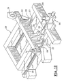
- FIG. 12 is a detailed view of control of the movement of a tool carriage of FIG. 9 ;
- FIG. 13 shows the embodiment of a mandrel with three sectors
- FIG. 14 shows the embodiment of a mandrel with five sectors.
- FIGS. 1 to 3 there is shown schematically a mandrel 1 with keys, according to the invention, respectively in its molding configuration ( FIGS. 1 and 2 ) and in its unmolding configuration ( FIG. 3 ).
- the mandrel 1 is of generally tubular shape and constituted by four sections or sectors, namely a so-called fixed sector 2 on opposite sides of which are associated two identical sectors 3 , called articulated sectors because they are connected to the fixed sector 2 each by a pair of hinges 4 .
- the fourth sector 5 is an independent sector interposed between the two articulated sectors 3 . It is lockable in place on the two adjacent sectors 3 by locks 6 ( FIG. 2 ) secured to the key sector 5 and coacting with keepers 7 fixed on the sectors 3 facing latches of locks 6 .
- Sectors 2 , 3 , 5 in the molding position of the mandrel 1 , define an external surface which corresponds to the internal wall in contact with the air flow which enters the fan channel of the air intake panel to be produced.
- FIG. 4 shows the mandrel 1 of FIGS. 1 and 2 on which has been emplaced for example by winding, banding or draping a resistive layer 8 constituting one of the elements of an air inlet panel without clips in the sense defined above.
- the mandrel 1 is inserted between two end flanges 9 a , 9 b , connected by ties 10 , the flanges bearing by their periphery on the sector of the sections.
- sockets 11 permitting the transport of the mandrel and its emplacement on a device for driving in rotation (not shown) of the mandrel 1 about its axis disposed for example horizontally.
- FIG. 5 shows the mandrel 1 of FIG. 4 , without its flanges 9 a , 9 b and in place on a cradle 12 for passage for example into an oven or an autoclave to polymerize the resin of the resistive layer 8 .
- the mandrel 1 rests on peripheral shoes 13 . It is however to be noted that the mandrel 1 could enter the oven or autoclave without first having its flanges removed.
- FIGS. 6 to 8 show an embodiment of the structure of the sectors of mandrel 1 .
- FIG. 6 there is shown a fixed sector 2 , an articulated sector 3 and a key sector 5 , all constituted by a framework formed by parallel uprights 14 interconnected on the internal side by parallel flanged cross-pieces 15 and, on the outer side, by a thin sheet 16 whose external surface defines the molding surface of the mandrel.
- the locks 6 of the key sector 5 are fixed on reinforced lateral uprights 14 ′ and coact with keepers 7 also fixed on reinforced lateral uprights 14 ′′ of the articulated section 3 .
- each hinge 4 for articulation between the sectors 2 and 3 are fixed, on the one hand ( 4 a ) on the uprights 14 of the fixed sector 2 and, on the other hand ( 4 b ) on a plate 17 connecting two cross-pieces 15 of the sector 3 .
- FIG. 8 is a fragmentary top plan view of the structure of FIG. 6 , at the junction between the key sector 5 and one of the articulated sectors 3 .
- the lock 6 is carried by a plate 18 itself fixed to the lateral upright 14 ′ of the key sector 5 .
- the latch 19 of the lock passes through the wall of the upright 14 ′ and that of the lateral upright 14 ′′ of the sector 3 and engages in the keeper 7 .
- the latch 19 is moved with the help of means described later with reference to FIG. 11 .
- FIGS. 9 to 12 show an embodiment of the means adapted to place the mandrel 1 in one or the other of its molding configurations ( FIG. 1 ) and un-molding configurations ( FIG. 3 ).
- These means comprise a tubular steel chassis 20 of generally octagonal shape, defining a first movement track 21 diametral to the octagonal structure, flanked by two symmetrical movement tracks 22 , converging in a direction substantially from one of the ends of said first track 21 .
- the track 21 is defined by two horizontal parallel beams 23 .
- a crosspiece 24 carrying two pins 25 adapted to support and center in vertical position the fixed sector 2 of the mandrel.
- sockets 26 adapted to engage over the pins 25 , as shown in FIG. 10 .
- a carriage 29 On the rails 27 move, by means of shoes 28 ( FIG. 12 ), a carriage 29 whose end (outer side) carries a cross-piece 30 provided with two support and centering pins 31 , analogous to the pins 25 and adapted to receive sockets 32 analogous to the sockets 26 , provided at the lower end ( FIG. 6 ) of uprights 14 of the key sector 5 .
- the carriage 29 is moved by a screw 33 driving a nut 34 secured to the carriage 29 .
- the screw 33 turns in the carriage 20 and is provided at its external end with a return angle 35 for controlling the screw either manually or by pneumatic screwing.
- the carriage 29 carries a post 36 supporting two devices for actuating two pairs of locks 6 .
- FIG. 11 shows in greater detail the actuating device of the upper pair of locks of the key sector 5 .
- Each device comprises a control rod constituted by two lateral returns 37 whose ends in the form of hooks 38 coact with the complementary ends 39 ( FIGS. 6 and 8 ) of the latches 19 of the locks 6 .
- the locks 37 are articulated on a head 40 movable vertically in guide slides 41 fixed to the post 36 , under the action of the rod 42 of a jack 43 also fixed to the post.
- the ends 38 of the returns 37 are held by guides 44 secured to the post 36 .
- FIG. 10 there is partially shown the mandrel 1 in molding position, directly over its rest position on the chassis 20 .
- the mandrel is simply disposed on the pins 25 (fixed sector 2 ), on the pins 31 (key sector 5 ) and on the pins 49 (articulated sectors 3 ), the carriages 29 and 46 being in one of their two end positions on their respective movement tracks 21 and 22 .
- the unlocking of the locks 6 is effected by retracting the rod of the jacks 43 , 43 ′, then the carriage 29 is moved in the direction of the center of the chassis 20 , the carriages 46 being still stationary and locked.
- the carriages 46 can be actuated, simultaneously or not, to cause to pivot inwardly the articulated sectors 3 by rotation about the axis of the hinges 4 , the sectors being driven by the pins 49 .
- the mandrel 1 is replaced on the chassis 20 , either after polymerization of the resistive layer so as to recover this latter, the other elements of the sandwich defining the air intake panel being emplaced according to other techniques, or after final polymerization of said sandwich, so as to recover the panel for its finishing, all the elements of the panel being emplaced on the mandrel from the outset.
- the sectors S 4 to S 7 abut.
- the articulated sectors S 4 to S 7 are first folded toward the center of the mandrel as shown at S′ 4 to S′ 7 in FIG. 14 , then the key sector S 8 is moved toward the center of the mandrel at S′ 8 .
- the mandrel comprises an independent and movable key sector, the other sectors being articulated to each other or movable so as to be retractable inwardly of the mandrel.
Landscapes
- Engineering & Computer Science (AREA)
- Chemical & Material Sciences (AREA)
- Combustion & Propulsion (AREA)
- Mechanical Engineering (AREA)
- Manufacturing & Machinery (AREA)
- Aviation & Aerospace Engineering (AREA)
- General Engineering & Computer Science (AREA)
- Transportation (AREA)
- Moulds For Moulding Plastics Or The Like (AREA)
- Moulding By Coating Moulds (AREA)
- Blow-Moulding Or Thermoforming Of Plastics Or The Like (AREA)
- Portable Nailing Machines And Staplers (AREA)
- Scissors And Nippers (AREA)
Applications Claiming Priority (2)
| Application Number | Priority Date | Filing Date | Title |
|---|---|---|---|
| FR0208014A FR2841494B1 (fr) | 2002-06-27 | 2002-06-27 | Outillage de moulage a clef notamment pour la realisation d'entree d'air sans eclisse |
| FR0208014 | 2002-06-27 |
Publications (2)
| Publication Number | Publication Date |
|---|---|
| US20040065775A1 US20040065775A1 (en) | 2004-04-08 |
| US7125237B2 true US7125237B2 (en) | 2006-10-24 |
Family
ID=29717117
Family Applications (1)
| Application Number | Title | Priority Date | Filing Date |
|---|---|---|---|
| US10/606,794 Expired - Lifetime US7125237B2 (en) | 2002-06-27 | 2003-06-27 | Tooling for molding with keys particularly for the production of air intakes without clips |
Country Status (6)
| Country | Link |
|---|---|
| US (1) | US7125237B2 (de) |
| EP (1) | EP1375111B1 (de) |
| AT (1) | ATE418436T1 (de) |
| CA (1) | CA2430175A1 (de) |
| DE (1) | DE60325444D1 (de) |
| FR (1) | FR2841494B1 (de) |
Cited By (10)
| Publication number | Priority date | Publication date | Assignee | Title |
|---|---|---|---|---|
| US20070062022A1 (en) * | 2005-09-21 | 2007-03-22 | Rohr, Inc. | Method and apparatus for making a tubular composite structure |
| EP2103404A2 (de) | 2008-03-21 | 2009-09-23 | Rohr, Inc. | Vorrichtung und Verfahren zum Herstellen einer rohrförmigen Verbundtrommel |
| US20100109208A1 (en) * | 2008-11-03 | 2010-05-06 | Claude Marc Hubert | Multi-segment tool and method for composite formation |
| US20120297602A1 (en) * | 2009-12-25 | 2012-11-29 | Kawasaki Jukogyo Kabushiki Kaisha | Disassembling method of mandrel used for manufacturing composite material structure and disassembling apparatus of mandrel |
| US9290274B2 (en) | 2014-06-02 | 2016-03-22 | Mra Systems, Inc. | Acoustically attenuating sandwich panel constructions |
| US11085640B2 (en) * | 2018-07-25 | 2021-08-10 | Sanfran Aircraft Engines | Production of a combustion chamber made of composite material |
| US11214387B2 (en) * | 2019-02-15 | 2022-01-04 | Airbus Operations Sas | Assembly method for an air intake of a jet engine of an aircraft |
| US11780359B2 (en) | 2016-12-20 | 2023-10-10 | Michael Kloepfer | Cylindrical semi-trailer |
| US11840398B2 (en) | 2017-09-22 | 2023-12-12 | Titan Trailers Inc. | Quasi-cylindrical cargo container and construction |
| US11850989B2 (en) * | 2016-12-20 | 2023-12-26 | Titan Trailers Inc. | Cylindrical cargo container construction |
Families Citing this family (11)
| Publication number | Priority date | Publication date | Assignee | Title |
|---|---|---|---|---|
| ITTO20060463A1 (it) * | 2006-06-23 | 2007-12-24 | Alenia Aeronautica Spa | Apparecchiatura e procedimento per la fabbricazione di un tronco di fusoliera |
| US8245750B2 (en) * | 2008-02-11 | 2012-08-21 | Rohr, Inc. | Segmented mandrel for high temperature bonding of metallic axisymmetric shells having complex curvatures |
| GB0810870D0 (en) * | 2008-06-13 | 2008-07-23 | Advanced Composite Components | Tooling |
| JP5576651B2 (ja) | 2009-12-25 | 2014-08-20 | 川崎重工業株式会社 | 複合材料構造物製造用マンドレルの組立方法およびマンドレルの組立装置 |
| RU2482028C1 (ru) * | 2011-12-21 | 2013-05-20 | Открытое акционерное общество "Национальный институт авиационных технологий" (ОАО НИАТ) | Стапель для сборки воздухозаборника двигателя летательного аппарата |
| ITTO20120285A1 (it) * | 2012-03-30 | 2013-10-01 | Alenia Aermacchi Spa | Sistema bloccaggio settori appartenenti ad un dispositivo per la realizzazione di una sezione di fusoliera di un aereo |
| FR2991628A1 (fr) * | 2012-06-12 | 2013-12-13 | Aircelle Sa | Ensemble d'outillage pour la fabrication d'une piece composite et procede de fabrication d'une piece composite. |
| CN103192330B (zh) * | 2013-03-25 | 2014-11-05 | 广州飞机维修工程有限公司 | 一种民航客机反推c涵道的修理夹具 |
| US9604438B2 (en) | 2014-04-30 | 2017-03-28 | The Boeing Company | Methods and apparatus for noise attenuation in an engine nacelle |
| US9708072B2 (en) | 2014-04-30 | 2017-07-18 | The Boeing Company | Aircraft engine nacelle bulkheads and methods of assembling the same |
| FR3101063B1 (fr) * | 2019-09-23 | 2021-09-24 | Safran Aircraft Engines | Outillage de fermeture de demi-capots de nacelle |
Citations (9)
| Publication number | Priority date | Publication date | Assignee | Title |
|---|---|---|---|---|
| US1835986A (en) | 1927-10-12 | 1931-12-08 | Nat Rubber Machinery Co | Collapsible tire building form |
| DE1262570B (de) | 1964-06-18 | 1968-03-07 | Mueller Ernst Kg | Hohldorn zum Herstellen von aus schraubenlinienfoermig gewickelten Kunststoffstreifen bestehenden Rohren oder Behaeltermaenteln beliebiger Laenge |
| DE1504597A1 (de) | 1965-11-06 | 1969-05-14 | Mueller Geb Schneider Hedwig I | Hohldorn zum Herstellen von aus schraubenfoermig gewickelten Kunststoffstreifen bestehenden Rohren oder Behaeltermaenteln |
| DE2259690A1 (de) | 1972-12-06 | 1974-06-12 | Bautenberg Gmbh | Hohler wickeldorn |
| DE2352373A1 (de) | 1973-10-18 | 1975-04-24 | Hermann Sarres | Wickeldorn zur herstellung von zylindrischen koerpern aus wickel- oder spritzfaehigen kunststoffen |
| US4278490A (en) * | 1979-12-21 | 1981-07-14 | Owens-Corning Fiberglas Corporation | Sleeve for changing diameter of collapsible mandrel |
| US4436574A (en) * | 1982-12-13 | 1984-03-13 | Eagle-Picher Industries, Inc. | Radial mandrel |
| EP0184759A2 (de) * | 1984-12-12 | 1986-06-18 | Dino Piccioli | Apparat zur diskontinuierlichen Herstellung rohrförmiger Gebilde oder daraus aufgebauter Gegenstände |
| US4610422A (en) * | 1984-02-08 | 1986-09-09 | Georg Prinzing Gmbh & Co. Kg Betonformen- Und Maschinenfabrik | Moulding apparatus for shaping concrete parts |
-
2002
- 2002-06-27 FR FR0208014A patent/FR2841494B1/fr not_active Expired - Fee Related
-
2003
- 2003-05-30 CA CA002430175A patent/CA2430175A1/fr not_active Abandoned
- 2003-06-11 DE DE60325444T patent/DE60325444D1/de not_active Expired - Lifetime
- 2003-06-11 EP EP03362007A patent/EP1375111B1/de not_active Expired - Lifetime
- 2003-06-11 AT AT03362007T patent/ATE418436T1/de not_active IP Right Cessation
- 2003-06-27 US US10/606,794 patent/US7125237B2/en not_active Expired - Lifetime
Patent Citations (9)
| Publication number | Priority date | Publication date | Assignee | Title |
|---|---|---|---|---|
| US1835986A (en) | 1927-10-12 | 1931-12-08 | Nat Rubber Machinery Co | Collapsible tire building form |
| DE1262570B (de) | 1964-06-18 | 1968-03-07 | Mueller Ernst Kg | Hohldorn zum Herstellen von aus schraubenlinienfoermig gewickelten Kunststoffstreifen bestehenden Rohren oder Behaeltermaenteln beliebiger Laenge |
| DE1504597A1 (de) | 1965-11-06 | 1969-05-14 | Mueller Geb Schneider Hedwig I | Hohldorn zum Herstellen von aus schraubenfoermig gewickelten Kunststoffstreifen bestehenden Rohren oder Behaeltermaenteln |
| DE2259690A1 (de) | 1972-12-06 | 1974-06-12 | Bautenberg Gmbh | Hohler wickeldorn |
| DE2352373A1 (de) | 1973-10-18 | 1975-04-24 | Hermann Sarres | Wickeldorn zur herstellung von zylindrischen koerpern aus wickel- oder spritzfaehigen kunststoffen |
| US4278490A (en) * | 1979-12-21 | 1981-07-14 | Owens-Corning Fiberglas Corporation | Sleeve for changing diameter of collapsible mandrel |
| US4436574A (en) * | 1982-12-13 | 1984-03-13 | Eagle-Picher Industries, Inc. | Radial mandrel |
| US4610422A (en) * | 1984-02-08 | 1986-09-09 | Georg Prinzing Gmbh & Co. Kg Betonformen- Und Maschinenfabrik | Moulding apparatus for shaping concrete parts |
| EP0184759A2 (de) * | 1984-12-12 | 1986-06-18 | Dino Piccioli | Apparat zur diskontinuierlichen Herstellung rohrförmiger Gebilde oder daraus aufgebauter Gegenstände |
Cited By (26)
| Publication number | Priority date | Publication date | Assignee | Title |
|---|---|---|---|---|
| US7707708B2 (en) | 2005-09-21 | 2010-05-04 | Rohr, Inc. | Apparatus for making a tubular composite structure |
| US20070062022A1 (en) * | 2005-09-21 | 2007-03-22 | Rohr, Inc. | Method and apparatus for making a tubular composite structure |
| US20100170633A1 (en) * | 2005-09-21 | 2010-07-08 | Rohr, Inc. | Method and Apparatus for Making a Tubular Composite Structure |
| US7861394B2 (en) | 2005-09-21 | 2011-01-04 | Rohr, Inc. | Method for making a tubular composite structure |
| EP2450171A1 (de) | 2008-03-21 | 2012-05-09 | Rohr, Inc. | Vorrichtung und Verfahren zum Herstellen einer rohrförmigen Verbundtrommel |
| EP2103404A2 (de) | 2008-03-21 | 2009-09-23 | Rohr, Inc. | Vorrichtung und Verfahren zum Herstellen einer rohrförmigen Verbundtrommel |
| US7640961B2 (en) | 2008-03-21 | 2010-01-05 | Rohr, Inc. | Apparatus and method for making a tubular composite barrel |
| US20100059185A1 (en) * | 2008-03-21 | 2010-03-11 | Rohr, Inc. | Apparatus and Method for Making a Tubular Composite Barrel |
| US8012286B2 (en) * | 2008-03-21 | 2011-09-06 | Rohr, Inc. | Apparatus and method for making a tubular composite barrel |
| US8394315B2 (en) | 2008-11-03 | 2013-03-12 | Rohr, Inc. | Multi-segment tool and method for composite formation |
| US20100109208A1 (en) * | 2008-11-03 | 2010-05-06 | Claude Marc Hubert | Multi-segment tool and method for composite formation |
| USRE46321E1 (en) | 2008-11-03 | 2017-02-28 | Rohr, Inc. | Multi-segment tool and method for composite formation |
| US8025499B2 (en) | 2008-11-03 | 2011-09-27 | Rohr, Inc. | Multi-segment tool and method for composite formation |
| US20120297602A1 (en) * | 2009-12-25 | 2012-11-29 | Kawasaki Jukogyo Kabushiki Kaisha | Disassembling method of mandrel used for manufacturing composite material structure and disassembling apparatus of mandrel |
| US9021678B2 (en) * | 2009-12-25 | 2015-05-05 | Kawasaki Jukogyo Kabushiki Kaisha | Disassembling method of mandrel used for manufacturing composite material structure and disassembling apparatus of mandrel |
| US9522487B2 (en) | 2009-12-25 | 2016-12-20 | Kawasaki Jukogyo Kabushiki Kaisha | Disassembling method of mandrel used for manufacturing composite material structure and disassembling apparatus of mandrel |
| US9290274B2 (en) | 2014-06-02 | 2016-03-22 | Mra Systems, Inc. | Acoustically attenuating sandwich panel constructions |
| US11850989B2 (en) * | 2016-12-20 | 2023-12-26 | Titan Trailers Inc. | Cylindrical cargo container construction |
| US12570199B2 (en) | 2016-12-20 | 2026-03-10 | Titan Trailers Inc. | Cylindrical cargo container construction |
| US11780359B2 (en) | 2016-12-20 | 2023-10-10 | Michael Kloepfer | Cylindrical semi-trailer |
| US12234085B2 (en) | 2017-09-22 | 2025-02-25 | Titan Trailers Inc. | Quasi-cylindrical cargo container and construction |
| US11840398B2 (en) | 2017-09-22 | 2023-12-12 | Titan Trailers Inc. | Quasi-cylindrical cargo container and construction |
| US12378064B2 (en) | 2017-09-22 | 2025-08-05 | Titan Trailers Inc. | Quasi-cylindrical cargo container and construction |
| US12466639B2 (en) | 2017-09-22 | 2025-11-11 | Titan Trailers Inc. | Quasi-cylindrical cargo container and construction |
| US11085640B2 (en) * | 2018-07-25 | 2021-08-10 | Sanfran Aircraft Engines | Production of a combustion chamber made of composite material |
| US11214387B2 (en) * | 2019-02-15 | 2022-01-04 | Airbus Operations Sas | Assembly method for an air intake of a jet engine of an aircraft |
Also Published As
| Publication number | Publication date |
|---|---|
| EP1375111A2 (de) | 2004-01-02 |
| FR2841494A1 (fr) | 2004-01-02 |
| FR2841494B1 (fr) | 2005-11-25 |
| CA2430175A1 (fr) | 2003-12-27 |
| US20040065775A1 (en) | 2004-04-08 |
| EP1375111B1 (de) | 2008-12-24 |
| EP1375111A3 (de) | 2007-11-14 |
| DE60325444D1 (de) | 2009-02-05 |
| ATE418436T1 (de) | 2009-01-15 |
Similar Documents
| Publication | Publication Date | Title |
|---|---|---|
| US7125237B2 (en) | Tooling for molding with keys particularly for the production of air intakes without clips | |
| JP3811739B2 (ja) | 複合ストリンガ組立機械 | |
| US9764499B2 (en) | Structures using composite modules and structures made thereby | |
| US8916010B2 (en) | Composite manufacturing method | |
| JP2008522898A (ja) | 一体型バレルアセンブリカート | |
| US20090294625A1 (en) | Cradle arrangement | |
| EP2072237B1 (de) | System und Verfahren für den Auf- und Abbau einer Reifenvulkanisierform | |
| EP2072226A1 (de) | Ladevorrichtung und Verfahren für den Auf- und Abbau einer Reifenhärtungsform | |
| US8431062B2 (en) | Tire unloading apparatus and method in a curing line | |
| JPS6031659B2 (ja) | タイヤ製造用ホールドを取扱う方法及び装置 | |
| CN103358561B (zh) | 用于对制造飞机机身的装置的扇区进行定位的系统 | |
| CN114737746B (zh) | 一种铝合金建筑模板 | |
| EP2072229B1 (de) | Reifenbaukernauf- und Abbaustation und Verfahren | |
| JPH0790535B2 (ja) | コンクリート製品成形用型枠装置 | |
| CN120057803A (zh) | 一种机电安装施工用升降设备 | |
| US7891962B2 (en) | Tire building core manipulator apparatus | |
| CN115680452B (zh) | 一种染色釜门盖快开装置及其方法 | |
| JP2001047522A (ja) | 大型円筒frp部品の脱型方法及び脱型装置 | |
| EP2072231A1 (de) | Vorrichtung und Verfahren zur Demontage eines Reifenbaukerns | |
| EP2072239B1 (de) | Reifenbaukernsegmentmanipuliervorrichtung und Verfahren | |
| JPH05124023A (ja) | 型枠装置 | |
| CN223104163U (zh) | 一种营房拼接固定工装 | |
| CN212372389U (zh) | 一种预制箱梁整体抽拔式芯模装置 | |
| CN120622373A (zh) | 一种用于更换gis设备的维修转运平台 | |
| CN121083825A (zh) | 无内衬复合材料贮箱伞型可伸缩成型模具及成型方法 |
Legal Events
| Date | Code | Title | Description |
|---|---|---|---|
| AS | Assignment |
Owner name: AIRBUS FRANCE, FRANCE Free format text: ASSIGNMENT OF ASSIGNORS INTEREST;ASSIGNORS:BUGE, MICHEL;LALANE, JACQUES;PORTE, ALAIN;AND OTHERS;REEL/FRAME:014152/0548 Effective date: 20030707 |
|
| STCF | Information on status: patent grant |
Free format text: PATENTED CASE |
|
| FPAY | Fee payment |
Year of fee payment: 4 |
|
| AS | Assignment |
Owner name: AIRBUS OPERATIONS SAS, FRANCE Free format text: MERGER;ASSIGNOR:AIRBUS FRANCE;REEL/FRAME:026298/0269 Effective date: 20090630 |
|
| FPAY | Fee payment |
Year of fee payment: 8 |
|
| MAFP | Maintenance fee payment |
Free format text: PAYMENT OF MAINTENANCE FEE, 12TH YEAR, LARGE ENTITY (ORIGINAL EVENT CODE: M1553) Year of fee payment: 12 |