EP2072231A1 - Vorrichtung und Verfahren zur Demontage eines Reifenbaukerns - Google Patents
Vorrichtung und Verfahren zur Demontage eines Reifenbaukerns Download PDFInfo
- Publication number
- EP2072231A1 EP2072231A1 EP08171819A EP08171819A EP2072231A1 EP 2072231 A1 EP2072231 A1 EP 2072231A1 EP 08171819 A EP08171819 A EP 08171819A EP 08171819 A EP08171819 A EP 08171819A EP 2072231 A1 EP2072231 A1 EP 2072231A1
- Authority
- EP
- European Patent Office
- Prior art keywords
- core
- segment
- assembly
- tire
- segments
- Prior art date
- Legal status (The legal status is an assumption and is not a legal conclusion. Google has not performed a legal analysis and makes no representation as to the accuracy of the status listed.)
- Withdrawn
Links
Images


Classifications
-
- B—PERFORMING OPERATIONS; TRANSPORTING
- B29—WORKING OF PLASTICS; WORKING OF SUBSTANCES IN A PLASTIC STATE IN GENERAL
- B29D—PRODUCING PARTICULAR ARTICLES FROM PLASTICS OR FROM SUBSTANCES IN A PLASTIC STATE
- B29D30/00—Producing pneumatic or solid tyres or parts thereof
- B29D30/0016—Handling tyres or parts thereof, e.g. supplying, storing, conveying
-
- B—PERFORMING OPERATIONS; TRANSPORTING
- B29—WORKING OF PLASTICS; WORKING OF SUBSTANCES IN A PLASTIC STATE IN GENERAL
- B29C—SHAPING OR JOINING OF PLASTICS; SHAPING OF MATERIAL IN A PLASTIC STATE, NOT OTHERWISE PROVIDED FOR; AFTER-TREATMENT OF THE SHAPED PRODUCTS, e.g. REPAIRING
- B29C33/00—Moulds or cores; Details thereof or accessories therefor
- B29C33/44—Moulds or cores; Details thereof or accessories therefor with means for, or specially constructed to facilitate, the removal of articles, e.g. of undercut articles
- B29C33/48—Moulds or cores; Details thereof or accessories therefor with means for, or specially constructed to facilitate, the removal of articles, e.g. of undercut articles with means for collapsing or disassembling
- B29C33/485—Moulds or cores; Details thereof or accessories therefor with means for, or specially constructed to facilitate, the removal of articles, e.g. of undercut articles with means for collapsing or disassembling cores or mandrels
-
- B—PERFORMING OPERATIONS; TRANSPORTING
- B29—WORKING OF PLASTICS; WORKING OF SUBSTANCES IN A PLASTIC STATE IN GENERAL
- B29C—SHAPING OR JOINING OF PLASTICS; SHAPING OF MATERIAL IN A PLASTIC STATE, NOT OTHERWISE PROVIDED FOR; AFTER-TREATMENT OF THE SHAPED PRODUCTS, e.g. REPAIRING
- B29C35/00—Heating, cooling or curing, e.g. crosslinking or vulcanising; Apparatus therefor
- B29C35/02—Heating or curing, e.g. crosslinking or vulcanizing during moulding, e.g. in a mould
-
- B—PERFORMING OPERATIONS; TRANSPORTING
- B29—WORKING OF PLASTICS; WORKING OF SUBSTANCES IN A PLASTIC STATE IN GENERAL
- B29D—PRODUCING PARTICULAR ARTICLES FROM PLASTICS OR FROM SUBSTANCES IN A PLASTIC STATE
- B29D30/00—Producing pneumatic or solid tyres or parts thereof
- B29D30/06—Pneumatic tyres or parts thereof (e.g. produced by casting, moulding, compression moulding, injection moulding, centrifugal casting)
- B29D30/0601—Vulcanising tyres; Vulcanising presses for tyres
- B29D30/0645—Devices for inserting vulcanising cores, i.e. bladders, into the tyres; Closing the press in combination herewith
-
- B—PERFORMING OPERATIONS; TRANSPORTING
- B29—WORKING OF PLASTICS; WORKING OF SUBSTANCES IN A PLASTIC STATE IN GENERAL
- B29D—PRODUCING PARTICULAR ARTICLES FROM PLASTICS OR FROM SUBSTANCES IN A PLASTIC STATE
- B29D30/00—Producing pneumatic or solid tyres or parts thereof
- B29D30/06—Pneumatic tyres or parts thereof (e.g. produced by casting, moulding, compression moulding, injection moulding, centrifugal casting)
- B29D30/0601—Vulcanising tyres; Vulcanising presses for tyres
- B29D30/0649—Devices for removing vulcanising cores, i.e. bladders, from the tyres; Opening the press in combination herewith
-
- B—PERFORMING OPERATIONS; TRANSPORTING
- B29—WORKING OF PLASTICS; WORKING OF SUBSTANCES IN A PLASTIC STATE IN GENERAL
- B29D—PRODUCING PARTICULAR ARTICLES FROM PLASTICS OR FROM SUBSTANCES IN A PLASTIC STATE
- B29D30/00—Producing pneumatic or solid tyres or parts thereof
- B29D30/06—Pneumatic tyres or parts thereof (e.g. produced by casting, moulding, compression moulding, injection moulding, centrifugal casting)
- B29D30/08—Building tyres
- B29D30/10—Building tyres on round cores, i.e. the shape of the core is approximately identical with the shape of the completed tyre
- B29D30/12—Cores
-
- B—PERFORMING OPERATIONS; TRANSPORTING
- B29—WORKING OF PLASTICS; WORKING OF SUBSTANCES IN A PLASTIC STATE IN GENERAL
- B29C—SHAPING OR JOINING OF PLASTICS; SHAPING OF MATERIAL IN A PLASTIC STATE, NOT OTHERWISE PROVIDED FOR; AFTER-TREATMENT OF THE SHAPED PRODUCTS, e.g. REPAIRING
- B29C35/00—Heating, cooling or curing, e.g. crosslinking or vulcanising; Apparatus therefor
- B29C35/02—Heating or curing, e.g. crosslinking or vulcanizing during moulding, e.g. in a mould
- B29C35/08—Heating or curing, e.g. crosslinking or vulcanizing during moulding, e.g. in a mould by wave energy or particle radiation
- B29C35/0805—Heating or curing, e.g. crosslinking or vulcanizing during moulding, e.g. in a mould by wave energy or particle radiation using electromagnetic radiation
- B29C2035/0811—Heating or curing, e.g. crosslinking or vulcanizing during moulding, e.g. in a mould by wave energy or particle radiation using electromagnetic radiation using induction
-
- B—PERFORMING OPERATIONS; TRANSPORTING
- B29—WORKING OF PLASTICS; WORKING OF SUBSTANCES IN A PLASTIC STATE IN GENERAL
- B29L—INDEXING SCHEME ASSOCIATED WITH SUBCLASS B29C, RELATING TO PARTICULAR ARTICLES
- B29L2030/00—Pneumatic or solid tyres or parts thereof
-
- Y—GENERAL TAGGING OF NEW TECHNOLOGICAL DEVELOPMENTS; GENERAL TAGGING OF CROSS-SECTIONAL TECHNOLOGIES SPANNING OVER SEVERAL SECTIONS OF THE IPC; TECHNICAL SUBJECTS COVERED BY FORMER USPC CROSS-REFERENCE ART COLLECTIONS [XRACs] AND DIGESTS
- Y10—TECHNICAL SUBJECTS COVERED BY FORMER USPC
- Y10T—TECHNICAL SUBJECTS COVERED BY FORMER US CLASSIFICATION
- Y10T156/00—Adhesive bonding and miscellaneous chemical manufacture
- Y10T156/11—Methods of delaminating, per se; i.e., separating at bonding face
- Y10T156/1142—Changing dimension during delaminating [e.g., crushing, expanding, warping, etc.]
-
- Y—GENERAL TAGGING OF NEW TECHNOLOGICAL DEVELOPMENTS; GENERAL TAGGING OF CROSS-SECTIONAL TECHNOLOGIES SPANNING OVER SEVERAL SECTIONS OF THE IPC; TECHNICAL SUBJECTS COVERED BY FORMER USPC CROSS-REFERENCE ART COLLECTIONS [XRACs] AND DIGESTS
- Y10—TECHNICAL SUBJECTS COVERED BY FORMER USPC
- Y10T—TECHNICAL SUBJECTS COVERED BY FORMER US CLASSIFICATION
- Y10T156/00—Adhesive bonding and miscellaneous chemical manufacture
- Y10T156/11—Methods of delaminating, per se; i.e., separating at bonding face
- Y10T156/1168—Gripping and pulling work apart during delaminating
-
- Y—GENERAL TAGGING OF NEW TECHNOLOGICAL DEVELOPMENTS; GENERAL TAGGING OF CROSS-SECTIONAL TECHNOLOGIES SPANNING OVER SEVERAL SECTIONS OF THE IPC; TECHNICAL SUBJECTS COVERED BY FORMER USPC CROSS-REFERENCE ART COLLECTIONS [XRACs] AND DIGESTS
- Y10—TECHNICAL SUBJECTS COVERED BY FORMER USPC
- Y10T—TECHNICAL SUBJECTS COVERED BY FORMER US CLASSIFICATION
- Y10T156/00—Adhesive bonding and miscellaneous chemical manufacture
- Y10T156/19—Delaminating means
- Y10T156/1978—Delaminating bending means
Definitions
- the subject invention relates generally to automated tire manufacturing lines and more specifically to an apparatus and a method for disassembling a tire building core in an integrated tire manufacturing system.
- the core includes multiple segments extending generally radially from a central axis. Each core segment has an outer surface that, together with the other segment outer surfaces, define a toroidal outer surface on which a tire may be constructed.
- US-A- 2007-0125496 and US-A- 2007-0125497 disclose one such segmented core.
- An efficient apparatus and method for accomplishing core disassembly is, accordingly, desired and heretofore not achieved.
- the invention relates to an apparatus according to claim 1, a method according to claim 10 and a tire curing line according to claim 12.
- apparatus for disassembling a toroidally shaped core is provided.
- the core is configured to carry a cured tire and includes multiple core segments extending generally radially from a central axis.
- the apparatus includes a base; one or more segment positioning devices connected for movement relative to the base and operative to move one or more core segments from an assembled core position next to an adjacent core segment around the central axis to a radially inward position; and one or more segment removal devices operatively connected for engaging the one core segment at the radially inward position and removing the one segment from the radially inward position to a remote position external to the core.
- the segment removal device operatively moves the one segment from the remote position to a storage position and deposits the one segment at a storage station in a retrieval-ready orientation.
- the segment removal device may be configured to move in three axis of motion to relocate a core segment between the radially inward position and the storage position. All of the core segments may be likewise moved in sequence by the segment removal device in order to disassemble the core.
- the segment removal device may include a picking mechanism having a segment locating first pin operatively positioned to extend downward into a first socket in the one core segment, and a segment locking second pin operatively positioned to extend into a second socket extending into a forward side of the one core segment.
- the subject curing line 10 is shown as part of an integrated tire manufacturing line.
- the curing line 10 is shown to include a plurality of stations arranged in a linear array, however, other arrangements of the work stations may be utilized if desired to accommodate the facility and/or preferences of the user.
- the tire manufacturing line builds a tire from components applied to a segmented core dimensioned and configured close to the finished tire.
- US-A- 2004-0207116 incorporated by reference herein, a segmented mold for molding a tire is described.
- the mold has a central axis; a plurality of radially movable tread forming segments; two sidewall forming plates, a top sidewall forming plate, and a bottom sidewall forming plate; a top locking ring having a plurality of circumferentially spaced means for locking the segments, each means for locking providing a predetermined angular path for radially contracting the segments upon closing the mold in a locked position.
- the segmented mold for molding a tire has an enlarged opening for accepting a green tire assembly. The mold can accept the green tire and its building core internally while maintaining the tire's as-built dimensions very close to the as-molded dimensions.
- the mold receives a tire building core assembly, including segments combining to define an annular tire building surface and including a latching and handling mechanism.
- a tire building core assembly including segments combining to define an annular tire building surface and including a latching and handling mechanism.
- a tire building core assembly including segments combining to define an annular tire building surface and including a latching and handling mechanism.
- a core is disclosed in US-A- 2007-0125496 , and US-A-2007-0125497 , incorporated herein by reference.
- the mechanism provides a positive means of attachment between the tire building core in tire manufacture and any of the building, curing or other stations involved in the manufacturing process. Attachment points are located in each end of the core useful for transporting the core the core between stations.
- the mechanism allows for automatic attachment/detachment of the core into two halves and provides sufficient accuracy and rigidity for the motions required for precision tire manufacture.
- the mechanism consists of a cone shaped interface within the core together with linkage driven latching fingers.
- a tire curing station such as that described in US-A- 2005-0133149 , incorporated herein by reference, may be employed.
- a coil or group of coils is positioned to surround areas of the tire mold that require application of precise heat. The heating is specified through a recipe program supplied to the control unit.
- the curing line 10 is intended to be integrated into the tire manufacturing line described above for curing a green tire constructed on a core assembly 15.
- the line 10 includes an upper core manipulator 12, upender apparatus 14, and a lower core assembly station 16 that operatively engage a tire building core assembly 15.
- the upper core manipulator assembly 12 is a mobile assembly that generally moves the core assembly 15 along the curing line 10 between a mold assembly station 18 and a cure station 22 having an induction heat dome assembly 24 positioned adjacent thereto.
- a mold manipulator assembly 26 bridges over the curing line and moves an assembled mold containing the core and tire assembly 15 under electrical control from control panel 28 along a transport rail assembly 30 between the cure station 22 and the mold assembly station 18.
- Induction heating control panels 32 are positioned adjacent the induction dome assembly 24 and electrically control assembly 24 throughout the heating cure cycle.
- a conical docking interface 84 is used in stations 14, 16, 18, and 22 to couple with the lower half of the core and tire assembly 15, whereby locating and positioning the core and tire assembly 15 for operations conducted within such stations.
- FIG. 3 illustrates in enlarged detail the upper core manipulator assembly 12 constructed as a bridging support frame assembly and positioned to move reciprocally along the rail assembly 30 station to station.
- the upper core manipulator assembly 12 spans the lower core manipulator 16 and, with the lower core manipulator 16, comprises a core assembly/disassembly station 34.
- the station 34 includes multiple assemblies that operatively interact with the core and tire assembly. Such assemblies include a bottom spindle clamp assembly 84, an intermediate core segment support assembly 82, a lower segment handling assembly 80, and an upper tire unloading apparatus 36.
- the assemblies 84, 82, 80 and 36 constitute the lower core manipulator 16 and are oriented generally in a mutually stacked configuration as shown in FIG. 3 .
- the assemblies 36, 80, and 82 are generally circular in configuration, peripherally oriented about a common circular central opening 39.
- the bottom spindle clamp assembly 84 projects axially upward from the bottom of the station 34 into the opening 39.
- multiple operations are conducted at station 34 within the curing line 10.
- the core assembly and disassembly station 34 is the combination of the lower core manipulator 16 (sub-assemblies 36, 80, 82, and 84) and the upper core manipulator 12.
- tire unloading apparatus 36 is part of the lower core manipulator 16 and is shown positioned at the top of the manipulator 16 within station 34.
- the tire unloader 36 is supported by a vertical support post 38 and includes a tire gripping assembly 40.
- the assembly 40 includes a circular upper support plate 41 and a lower support plate 43 spaced below upper plate 41.
- the central axial opening 39 extends medially through each of the plates 41, 43. Spaced about the periphery of the opening 39 and facing inward is a plurality of elongate, generally vertically oriented tire gripping paddles 42. Eight paddles 42 are shown but more or fewer may be deployed if desired.
- the paddles 42 are generally L-shaped having a vertical plate portion 44 and a horizontal bottom flange 46 extending into opening 39.
- Linkage arms 48 connect the paddles 42 together to maintain the paddles in a radial orientation relative to the opening 39.
- An upper connecting link 52 is further provided to tie the paddles together as shown.
- Spaced apart sets of upper and lower actuation arms 52, 54 are pivotally coupled at remote ends to the paddles 42 and pivotally coupled at opposite ends to pivot rods 58.
- the arms 52, 54 are linked together to swing the paddles 42 in unison along an arcuate path radially inward and outward as the arms 52, 54 pivot about the pivot rods 58.
- the paddles 42 are mounted to pivot at the remote end of the arms 52, 54 to maintain a radially inward facing tire clamping orientation at the innermost extent of the arcuate path.
- the pivot rods 58 extend vertically between the plates 41, 43. Accordingly, paddles 42 move reciprocally in unison between a radially innermost tire clamping position and a radially outward tire release position as arms 54, 56 pivot.
- An air cylinder 60 is mounted and includes a drive shaft coupled to arms 54, 56.
- the drive shaft of the cylinder 60 is linked by a conventional linkage to the arms 54, 56 that are linked to each paddle 42. Accordingly, the drive shaft of cylinder 60, by way of reciprocal axial movement, imparts rotational movement to the arms 54, 56, whereby moving the arms 54, 56 and the paddles 42 connected thereto between the tire clamping and release positions as described above.
- a circular support frame 62 carries the tire gripping assembly 40 and is secured to a support stand 64.
- a ball screw mechanism 66 is driven by a servo-motor 68 and couples by means of drive linkage 69 to raise and lower the tire unloading assembly 36 along rails 70.
- Rails 70 are spaced apart and positioned to extend vertically up the post 38.
- a drive motor 72 is coupled to rotate the tire gripping assembly 40 180 degrees between the positions illustrated in FIGS. 12 and 13 .
- the assembly 40 is mounted to shaft 74.
- Motor 72 engages shaft 74 by means of clutch 76 to drive shaft 74, thus effecting programmed reciprocal pivotal movement of the assembly 40.
- Cables are routed to the unit by means of cable carrier 71.
- An encoder position sensor 78 controls pivotal movement of the assembly 40.
- the tire unloading apparatus 36 is shown positioned generally above the remaining sub-assemblies of lower core manipulator 16, namely the lower core segment handling assembly 80, a central core segment supporting apparatus 82, and a lower spindle clamping assembly 84.
- the lower spindle clamping assembly 84 provides an upward directed clamping mechanism 86 including a frustro-conical support 88 mounted to move vertically in reciprocal fashion within support column 87.
- a pneumatic cylinder 104 is mounted to move the mechanism 86 vertically along rails 96.
- An air cylinder 90 through a drive rod 92 is coupled to pivot four latch members 94 mounted within respective openings 95 within the support 88.
- the four latch members 94 reside within the openings 95 spaced equidistant and ninety degrees apart about the frustro-conical support 88.
- the latch members 94 are spring biased to an inward position that places and holds the latch members 94 within detents in a lower core spindle assembly 240.
- the latch members 94 are spring biased in the inward latched position until the rod 92 moves axially upward and cams the latch members 94 outward and out of their respective core spindle detents, whereby releasing the lower core assembly from the frustro-conical support 88 as will be further explained.
- US-A- 2007-0125496 shows and describes the attachment and release mechanisms employed between the core assembly and a clamping mechanism configured similarly as the clamping mechanism 86.
- the clamping mechanism 86 moves reciprocally in the vertical direction along rails 96.
- a freestanding support stand 98 is provided. Power and control cables are routed to the bottom spindle clamp assembly 84 from a control tower 100 along a cable support 102.
- An air cylinder 104 with an integrated rod clamping braking mechanism 93 is mounted to vertical support column 106 and reciprocally drives the assembly 86 along rails 96.
- a pair of support base members 108 support posts 110.
- a rectangular frame 111 is coupled to an upper end of the posts 110.
- the support frame 112 includes a circular plate 113. Circumferentially spaced about and projecting upward from a top surface of the plate 113 is a circular array of L-shaped arms 114, each having a pad 116 affixed to a remote end. Pads 116 are composed of abrasive resistant material such as bronze or plastic. While eight arms 114 are illustrated, corresponding to the number of segments within the lower core assembly, more or fewer arms may be employed if necessary for alternative core assembly configurations.
- a pair of air cylinders with a braking mechanism 118 attach to the posts 110 and act to reciprocally move the moveable support frame 112 along rails 120 that extend upwardly along the inward facing sides of the posts 110.
- the circumferential array of spaced apart L-shaped arms 114 define a circular array having a diameter allowing each of the arms 114 to support a respective segment component of a segmented core 234.
- FIGS. 5 , 10 , 11 , 11A, and 11B illustrate the lower segment handling assembly 80.
- the lower core segment handling assembly 80 is supported in a free standing frame 122 by support posts 121 connected by cross support braces 123.
- a circular array of eight radially extending alternating segment pin sub-assemblies 124, 127 are positioned on an upper top plate 125, the eight sub-assemblies corresponding to the eight core segments comprising the assembled annular core.
- Each sub-assembly 124, 127 has a servo-motor 126 coupled by a positive drive belt 128 to ball screw 130.
- the ball screw 130 is coupled to drive sub-assembly 132 axially along guide rails 134 as shown in FIG. 11 .
- a pin 136 Positioned at the forward end of the moveable frame 132 and projecting upward is a pin 136 supported by block 138.
- the pin 136 extends from a segment support surface 140 situated at a remote end of the block 138 and each pin is provided with a convex lead-in remote surface 142 to facilitate insertion of pin 136 into a respective segment pin-receiving aperture.
- Each pin 136 is thus reciprocally moveable in a radial direction along the plate 125 between an inward, segment engaging position and an outward storage position.
- the configuration of the pin array on surface 125 is such that the pins 136 are positioned to insert into appropriate respective apertures extending upwardly into respective core segments.
- a protective guard 144 covers the belt 128.
- the tilting pin assembly 124 is depicted in FIG. 11 and represents a key segment engaging assembly.
- the segmented core is assembled from smaller key segments 244 alternating with larger core segments 246 in a circular array.
- the four segment pin assemblies 124 and the four large segment pin assemblies 127 are in the radially outward position ( FIG. 10 ).
- the pins 136 of the four key segment engaging assemblies 124 project into respective key segments 244 from below and the pins 136 of the large segment engaging assemblies 127 project into respective large segments 246 from below.
- a cured tire 230 is positioned on the assembled core 234.
- the segments 244, 246 are moved radially to the center of the assembly 15 and removed one by one from the center opening of the core and the tire.
- the key segments 244 are first removed, one by one. Each key segment is moved radially inward by its assembly 124 to the center of the core and tire assembly 15.
- the segment is picked by an upper segment manipulator 146 carried by the upper core manipulator 12.
- the segment is lifted up and out of the center core position by the manipulator 146 and transported to a storage station on the manipulator 12.
- the moveable frame 132 of the assembly 124 is then retracted radially outward and placed back into its initial position.
- Each of the four key segment assemblies 124 is constructed to allow the pin 136 carried thereby to be tilted from the upright pin position of FIG. 11 into a tilted, near horizontal orientation shown in FIG. 38 .
- the tilting of each key segment assembly 124 occurs when the assembly is retracted into a radially outward storage position after delivering its key segment to the manipulator 146 at the center of the core assembly 15.
- Each of the four key segment assemblies 124 are tilted downward after unloading their respective key segments and returning to the radially outward storage position.
- the downward tilting of the key segment assemblies 124 allows sufficient clearance for each larger segment assembly 127 to move its larger segment 246 past the adjacent key segment assemblies 124 to the center of the core and tire assembly 15 for delivery to the manipulator 146.
- segment handling assemblies 124, 127 are returned to their respective radially outward storage positions shown in FIG. 10 .
- the key segment handling assemblies 124 are tilted upward and back into a vertical orientation in preparation for the core re-assembly procedure.
- the segment handling assemblies 124, 127 In the storage position, the segment handling assemblies 124, 127 generally take the form of the assembled core 15. However, the position of the key segment handling assemblies 124 in the retracted location is slightly radially inward relative to the large segment handling assemblies 127.
- the manipulator 146 delivers the core segments back to positions on their respective pins 136 in reverse order one by one, larger segments 246 first followed by the key segments 244.
- the key segments 244 are moved radially outward to engage against adjacent large segments to form the final assembled shape of the core 15.
- the key segments 244 retain the larger segments 246 into the assembled circular segmented core 234 by the segment surface to surface abutment referenced at 262 of FIG. 38 .
- the key segments 244 removed first from the circular array in order to allow removal of the larger segments 246 and returned last to the array in order to lock the larger core segments into place.
- the key segment handling assemblies 124 are similarly constructed to the large segment handling assemblies 127 except that the assemblies 124 mount the segment pin 136 on a pivoting block 133 at the forward end of the assembly to facilitate the downward tilting of the pin for clearance as described above.
- the segment handling assemblies 127 for each larger segment 246 are similarly constructed to assemblies 124 except that the tilting capability and, hence, mechanism is not necessary and, accordingly, not present.
- Each pin 136 for the larger assemblies 246 is mounted to a fixed block (not shown).
- the segments 244, 246 are removed one by one from the center of the core and tire assembly 15 during core disassembly to avoid the cured tire 120 on the core. Once the core has been disassembled and tire unloaded, the core segments 244, 246 are moved downward by the manipulator 146 onto the pins 136 in the radially outward position. The core is thus reassembled into final configuration segment by segment.
- An activation cylinder 135 is mounted on the frame 132 and includes an actuation rod coupled to the pin supporting block 138. Actuation of the cylinder 135 acts to pivot the pin 136 from a core segment engaging vertical position (shown in FIG. 11 ) to a storage position approaching horizontal as in FIG. 38 . Once all of the segments 244, 246 are disassembled, the pins 136 of the segment handling assemblies 124 are pivoted back into a vertical orientation to await reassembly of the core 234.
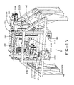
- FIGS. 14 , 15 , and 22 show the upper core manipulator assembly 12 to include an upper core segment manipulator 146 and an upper spindle latch mechanism 198.
- Bridging trusses form a support frame assembly 148 that includes a frame 222 carrying the core segment manipulator 146 and a frame 224 for carrying the upper spindle latch mechanism 198.
- the frame 222 includes a vertically repositionable inner frame 222A and an outer frame 222B and the frame 224 an inner frame 224A and an outer frame 224B.
- the core segment manipulator 146 includes an upper core segment handling mechanism 150 (shown in detail by FIG. 16 ) that mounts to the inner frame 222A.
- the upper core segment manipulator 146 further includes a core segment storage station 152 adjacent the handling mechanism 150.
- a pair of spaced apart horizontal plates 153 is located within the storage station 152, each plate 153 supporting a linear array of four spaced apart, upwardly directed pin members 151.
- the pins 151, four on each side of the storage station 152, are dimensioned for insertion into a respective core segment socket and function to support a core segment within the storage station 152.
- the eight pins 151 receive eight core segments in a disassembly sequence as will be describe, and temporarily store the segments until the procedure is reversed for core re-assembly.
- a gear box and servo-motor 154 is coupled by belt drive 156 to rotate a vertical shaft 158 360 degrees. Shaft 158 thereby rotates the upper core segment handling mechanism 150.
- the storage pins 151 within storage station 152 each extend from a respective pin support block 160. Each of the pins 151 is at a specific location in the storage station 152 determined by the core segment assigned to the pin. Each segment is picked by the core segment gripper 174 at the remote end of the core segment handling assembly 150.
- the horizontal pin 184 of gripper 174 is pivoted into a segment side socket 252 while the vertical pin 182 of the gripper 174 enters down into a segment vertical socket 250 ( FIG.35 ).
- Guide flange 173 assists in aligning the vertical pin 182 into a targeted segment socket.
- the assembly 150 is raised and may return to the core by a reverse procedure to locate and retrieve another core segment.
- the procedure is reversed in a reverse sequence in order to reassemble the upper core during a core reassembly operation. Once completely reassembled, the segmented core 234 is available for another new tire build operation.
- each core segment 244, 246 is pre-assigned within the storage station 152 to correspond with the sequence the segments 244, 246 are disassembled and assembled.
- the core 234 is constructed from alternating wedge shaped smaller key segments 244 and larger core segments 246.
- the key segments 244 entrap the larger segments 246 into the annular configuration of core 234 through an abutment of beveled segment surfaces 262. See FIG. 38 .
- the smaller key segments 244 are removed first to facilitate subsequent removal of the larger core segments 246.
- Each of the four of the key segments 244 are removed and placed in the storage station 152 first, followed by the four larger segments 246.
- the sequencing used in disassembly will be understood from FIG.
- each larger segment 246 adjacent to its neighboring key segment 244 in the storage station 152 expedites the disassembly of the upper core as well as expedites reassembly of the core in a reverse procedure because the proximity of neighboring key/large segment pairs in the core is maintained in the storage station 152.
- a radially inward face or side 251 of each segment 244, 246 is canted inwardly within the station 152 toward a center point "P" between the two sides of the station 152.
- the rotational travel of the gripper 174 necessary to deposit and to retrieve each segment is thereby minimized.
- the canted orientation of the front side 251 of each segment orients the vertical socket 250 and horizontal socket 252 of each segment toward the center point "P" where gripper 174 is stationed to provide the gripper 174 with oriented access to each segment 244, 246 whereby eliminating wasted motion and time.
- the upper core segment handling mechanism 150 is mounts to inner frame 222A that reciprocally moves along rails 167.
- a servo-motor/gear box 164 is coupled to drive the moveable frame 222A, and thereby the upper core segment handling mechanism 150, along vertically oriented rails 167.
- a servo-motor 168 is mounted to drive ball screw 172 which moves the upper core segment handling mechanism 150 in a radial direction along rails 170.
- a segment gripper assembly 174 including a mounting plate 175 from which a guide lead-in projection 173 depends. Arm 177 depends from base plate 176 at an acute angle.
- the segment gripper assembly 174 is connected to a remote end of arm 177 at a mounting plate 175.
- a support mount 179 extends from an underside of the mounting plate 175.
- Air cylinder 178 is pivotally coupled to the mount 179 at pin 181.
- a support arm 183 depends from the underside of the plate 175 and a vertical segment engaging pin 182 is secured by a screw 185 to the support arm 183.
- Pin 182 projects downward from the support arm 183 and is dimensioned for close downward receipt into a socket within each core segment as will be explained.
- a dependant pivot arm 180 is pivotally coupled to the remote end of an actuation rod of air cylinder 178 by pin 187.
- the pivot arm 180 is pivotally coupled by a lower pin 189 to the support arm 183.
- Actuation of the air cylinder 178 pivots the pivot arm 180 about pivot points 189, whereby moving a remote end of the pivot arm inside and outside of a passageway through the arm member 173.
- a segment side engaging pin 184 Secured to a remote end of the pivot arm 180 is a segment side engaging pin 184 which moves with the pivot arm remote end into and out of the passageway 188 through the arm member 173.
- a proximity switch 186 is mounted to the support arm 183 and controls the extent to which the pin 182 is inserted into each core segment by proximally detecting the presence of the core segment.
- a motor/gear box 165, 190 having an output shaft 192 is mounted to the frame 148 and drive shaft 192 is coupled to the core manipulator frame 224.
- the drive shaft 192 powers a reciprocal vertical movement of the core manipulator frame 224 along rails 192.
- Mounted to and depending from the frame 224 is an upper core spindle latch mechanism 198 shown in detail in FIGS. 18 and 19 .
- the upper core spindle latch mechanism 198 reciprocally moves in the vertical direction on the inner frame 224A of the frame assembly 224.
- the mechanism 198 as shown includes a frustro-conical nose 200 having four circumferentially spaced latch members 202.
- Members 202 pivot about a respective pivot pin 203 within respective openings 205 between an outward latched position in which members 202 protrude beyond an outer surface of the nose 200, and a retracted unlatched position in which each latch member 202 is within a respective passage 205.
- a cylindrical sleeve 204 extends axially within an upper housing 216 of the mechanism 198 and a co-axial actuation rod 206 is positioned within an axial bore 201 of the sleeve 204.
- the actuation rod is provided with an end cap 207.
- An air cylinder 208 is positioned above the housing 216 in axial alignment with the sleeve 204 and includes a push rod 209 coupled by a clevis 213 to the actuation rod 206.
- Axial motion of the actuation rod 206 operated the internal latching mechanism in the upper spindle assembly of a tire building core assembly 15, allowing it to be detached from the lower spindle assembly at the appropriate stage in the core disassembly process.
- a pair of air cylinders 210 mounts to opposite sides of the housing 216 surrounding the sleeve 204 and each cylinder 210 has a push rod 215 that is coupled to an angle bracket.
- Angle brackets 219 are positioned on either side of sleeve 204 and are attached to it by means of screws 218.
- Each latch member 202 attaches to the sleeve 204 by a fitting 212.
- the upper core spindle latch mechanism 198 is lowered by moving frame 224 downward as described above until nose 200 is received into an upper spindle assembly socket of a tire building core assembly.
- the latch members 202 pivot outward to engage recesses within the spindle assembly socket sidewalls.
- the latch members 202 load outward by the force applied by cylinders 210 into a latched relationship with the core recess.
- the upper core spindle latch mechanism 198 is thereby secured to the upper spindle assembly of a tire building core.
- the core subsequent to latching engagement with spindle latch mechanism 198, may be lifted and lowered axially by the mechanism 198 traveling along the rails 226.
- US-A- 2007-0125496 describes and shows the latching mechanism employed in attaching the upper core spindle latch mechanism 198 to the core and tire assembly 15.
- the upper core manipulator 12 is configured to suspend a core and tire assembly 15 attached to latching mechanism 198 a distance "H" above the feet 166 of the frame 148.
- the distance "H” is of sufficient height to create clearance between a core and tire assembly 15 suspended from the manipulator 12 and stations 16, 18, 22 comprising curing line 10. Accordingly, the clearance created by the height "H” allows the manipulator, for example, to transport a cured tire and core assembly 15 over a second tire and core assembly at another station. Multiple core and mold units may thereby be processed simultaneously at different locations within the line 10 whereby improving efficiency by reducing cycle time.
- the latch members 202 may be pivoted into a retracted unlatched position by axially moving the sleeve 204 within mechanism 198 upward under pressure from the air cylinders 210.
- the sleeve moves upward causing the linkages to pull the latch members 202 inward until each latch member 202 exits its respective detent in the core upper spindle assembly sidewalls and retracts each latch member 202 into its respective opening 205.
- the latch members 202 do not protrude beyond the outer surface of the frustro-conical nose 200.
- the nose 200 Upon movement of the latch members 202 within the respective openings 205 into the retracted position, the nose 200 is released from the upper spindle assembly socket and the core upper spindle latch mechanism 198 may be withdrawn from the upper spindle assembly socket by vertical movement of the core manipulator frame 196.
- the upper core manipulator 12 includes four vertically oriented guide rails forming outer frame 220B supporting the inner frame 222A for core segment manipulation.
- the frame 224A similarly moves vertically along a vertical set of rails 226 to raise and lower the latch mechanism 198.
- the latch mechanism 198 lifts the upper core spindle assembly 236 from a core and tire assembly 15 stationed on the lower core manipulator 16. Access to the core segments 244, 246 is thereby facilitated. Thereafter, the manipulator 12 moves along the rails 30 until the upper core segment handling assembly 150 is above the manipulator 16.
- the segments are sequentially disassembled from the assembled core by moving the segments 244, 246 radially inward using a coordinated motion between assembly 150 and the core segment handling assembly 80 and then axially moving the segments to escape the confines of the tire and core assembly 15 using assembly 150.
- the cured tire 230 is dropped from the unloader 36 after the segmented core 234 has been disassembled. Reassembly of the core is conducted in reverse fashion.
- the segments 224, 246 may be removed by radially moving them inward using only assembly 80 and then moving them axially with assembly 150. This allows assembly to be storing the previous segment while the current segment is being moved radially, thus reducing cycle time.
- the core and tire assembly 15 is shown to include a tire carcass 230 extending between a tire bead 232.
- the carcass 230 mounts to a segmented core 234 that includes an upper core spindle assembly 236 having a frustro-conical socket 238 extending therein along a longitudinal spindle axis.
- the core 234 further includes a lower core spindle assembly 240 having a frustro-conical socket 242 extending therein along a longitudinal spindle axis.
- the body of the core 234 is toroidally shaped formed by a plurality of alternating core small key segments 244 and core large segments 246, each segment having an outer surface portion that together define a toroidal outer surface surrounding a central axis.
- the core 234 in the assembled configuration is adapted to hold a green tire on the toroidal outer surface.
- the tire carcass 230 is constructed onto the core 234 at a tire building station (not shown).
- the assembly 15 consisting of the core 234 and green tire carcass 230 is transported to the upender apparatus 14 of curing line 10 where the assembly 15 is upended from an axial horizontal orientation to an axially vertical orientation.
- the upper core manipulator 12 traverses rails 30 to the upender 14 where the latching mechanism 198 is employed to latch into the upper spindle assembly 236 of the core and tire assembly 15.
- the mechanism 198 lifts the assembly 15 and transports the assembly 15 to the mold assembly station 22 where a multiple component mold is constructed around the assembly15.
- a plurality of electrical connector sockets 248 extend into ends of the core segments 244, 246. Also disposed within the ends of the core segments 244 is a pin socket 250. A horizontally extending bore 252 extends into the base of each segment 244, 246.
- the segments 244, 246 are composed of suitable material such as aluminum, each segment having a resistive heating element attached to the segment for heating the segment to a desired temperature during the curing cycle.
- Electrical conductors 256 are provided to provide electrical power to the segment heating elements. The conductors 256 are electrically connected to connectors within the electrical sockets 248 of each segment. The connectors within sockets 248 are engaged by pins in the spindle assemblies 236 and 240.
- U.S. Patent Application Serial No. 11/292,991 describes the electrical and mechanical components and connectors electrically and mechanically connecting the upper and lower core spindle assemblies 236, 240 with the segmented core 234.
- the tire building core assembly and disassembly station 34 is a part of the cure line assembly 10. Its purpose is to receive a tire building core 15 with a freshly cured tire 230 attached from the mold assembly station 18, disassemble the tire core piece-by-piece from inside the cured tire, transport the cured tire away from the main zone of the cure line 10, and then re-assemble the tire building segmented core 234 and place it back into the tire building process. All of this activity is preferably to be preformed in a totally automatic mode without a machine operator.
- the cure line 10 is shown in a preferred layout in FIGS. 1 and 2 . Other arrangements of the sundry stations within the line may be utilized to suit the preferences of or facilities of the user. As shown in FIG. 1 and previously explained, the stations of the cure line 10 are from right to left:
- Figure 3 shows the tire building core assembly and disassembly station 34.
- the station 34 is comprised of two main assemblies.
- the lower core manipulator station 16 which is fixed to the cure line foundation plate assembly, and the mobile upper core manipulator assembly 12, which is connected to the cure line rail transport assembly 30 and moves between the tire upender 14, the lower core assembly station 16, and the mold assembly station 18.
- the connection to the rail assembly 30 is not shown for clarity in FIG. 3 , and therefore, the upper core manipulator assembly 12 appears to be floating in space.
- FIGS. 4 and 5 The lower core manipulator assembly 16 is shown in FIGS. 4 and 5 .
- FIG. 6 shows the assembly in a cross-sectional view. This assembly includes four sub-assemblies: the bottom spindle clamp assembly 84, the core segment support assembly 82, the lower core segment handling assembly 80, and the tire unloader 36.
- the bottom spindle clamp assembly 84 is shown in FIGS. 7 and 8 . Its function is to remove one half of the tire building core spindle, namely the lower core spindle assembly 240.
- the clamp assembly 84 is actuated by the pneumatic cylinder 104 and traverses vertically on the set of linear guide rails 96.
- the tip or nose 88 of the clamp assembly 84 is tapered into a frustro-conical shape to mate with the tapered socket 242 on the tire building lower core spindle assembly 240.
- a rod clamp on the cylinder 104 is a braking mechanism used to maintain position.
- a second pneumatic cylinder 90 actuates a linkage at the tapered end to clamp the end of the tire building core spindle assembly 240 as described previously.
- the rod 92 actuates pivotal latch members 94 within respective openings 95 to extend the latch members 94 into and out of detent openings in the frustro-conical socket 242.
- This clamp linkage and tapered spindle connection are used in station 14 as well as station 16 within the curing line 10 as will be appreciated from FIGS. 1 and 2 .
- the clamp linkage and tapered spindle connection may further be utilized at a tire building station (not shown) to provide means for mechanically connecting to the core assembly 15.
- the core segment support assembly 82 is shown in FIG. 9 . Its function is to support the tire building core segments 244, 246 in eight places below the tire bead area so that the lower core spindle assembly 240 can be removed or inserted.
- the support moves vertically on linear guide rails 120 and is actuated by two pneumatic cylinders 118. Rod clamps on the cylinders are used to maintain the desired vertical position of the support 82.
- the lower core segment handling assembly 80 is shown in FIGS. 10 , 11 , 11A and 11B , and described in detail previously.
- Eight pins 136 are used to support the tire building core 234 after the lower and upper spindle assemblies 236, 240 have been removed.
- Each pin 136 is moved radially on linear rails 134 using a ball screw 130 driven by a servo-motor 126. See FIGS. 11 , 11A, and 11B . This radial movement is used to pull the respective core segment inward to allow the upper core segment handling assembly 150 to remove it upward from the cured tire.
- the tire unloader assembly 36 is shown in FIGS. 12 and 13 and described in detail previously.
- the tire unloader assembly 36 grips the outside diameter of a cured tire by means of the tire gripping paddles 42 driven by pneumatic cylinder 60 through arms 54, 56 as the tire building core segments 244, 246 are being removed, one by one. Thereafter, the unloader lifts the tire over the lower segment handling assembly 80, rotates 180 degrees about shaft 74 to the tire drop zone (rotated from the FIG. 12 position to the FIG. 13 unload position), and lowers the assembly 36 by means of ball screw 66 along rails 70 to the drop-off height. The tire is released by the paddles 42 at the drop-off height.
- FIGS. 38 , 39 , and 40 illustrate sequentially the operation of assembly 36.
- FIG. 38 is a sectional view showing clamping engagement of the paddles 42 against a tire carcass 230; and FIGS. 39 and 40 the tire carcass 230 being lifted and rotated for placement at a tire unload position and height represented by FIG. 40 .
- the upper core assembly station 12 is shown in FIGS. 14 and 15 .
- the station 12 is comprised of two mechanisms 150, 198 supported by sub-frames 222A, B, and 224A, B, respectively, within a common outside frame 148, which is mounted to the rail transport assembly 30 below.
- the first mechanism, the upper core segment handling assembly 150 has three primary axes of motion and is used to transport the individual core segments 244, 246 between positions on the pins 258 on the lower core segment handling assembly and the pins 151 in the segment storage station 152.
- the second mechanism, the upper core handling assembly 198 is used to grip and remove the upper spindle assembly 236 from the tire building core 234 to expose the individual core segments 244, 246 for removal.
- the upper core handling assembly 198 can position the complete core assembly at these stations: tire upender 14; core assembly and disassembly 34; and mold assembly and disassembly 18.
- the upper core segment handling assembly 150 is mounted to a sub-frame 222A which is attached to the main frame 222B through four linear guide assemblies. Three axes of movement are possible: vertical lift, rotation about the center of the tire, and radial movement.
- Precision vertical movement control is achieved by lifting or lowering the sub-frame 222A using two positive-drive belts 157, driven by a common drive shaft 193 connected to the output of a gearbox and servo-motor combination 164.
- the sub-frame 222A also supports a second servo-motor and gearbox combination 154 which uses a positive-drive belt 156 to rotate the center shaft 158 to the desire angular position. Full rotation from zero to 360 degrees is possible.
- This drive shaft 158 supports the radial positioning assembly 150 shown in FIG. 16 .
- the radial positioning assembly 150 uses another set of linear guides 170 and a ball screw 172 driven by a third servo-motor 168 to establish the desired radial position for the core segment gripper head 174 which is shown in FIGS. 17 and 17A .
- the gripper head 174 inserts a guide pin 182 into the top socket 250 of the core segment, and then uses a pneumatic cylinder 178 to actuate a link arm 180 to drive a conical pin 184 into a conical hole 252 in the core segment.
- Proximity switches 186 mounted on the cylinder 178 detect the position of the link arm 180, and a spring-loaded foot mechanism actuates a proximity switch to assure that the core segment is present.
- the core segment storage station or area 152 consists of two plates 153 with four pins 151 each mounted on either side of the upper core segment handling assembly frame 222.
- the pins 151 are similar to the pins 254 used on the lower core assembly station 34 to hold the core segments in place until the sequence calls for the tire building core 234 to be re-assembled.
- the pins 151 are placed such that they may be accessed using only the vertical, rotational, and radial axes of the upper core handling assembly 150 as shown at the bottom of FIG 15 and in FIGS. 41 and 42 .
- the upper core handling assembly 198 also uses a sub-frame 224A moving on four linear guide assemblies 226 to control vertical movement similar to the upper core segment handling assembly 150.
- a telescoping mechanism is used to conserve space.
- Two intermediate frames 224A, one on each side, are raised and lowered by two positive-drive belts 194, 196 connected to a common drive shaft 192 which is driven from the output of a gearbox and servo-motor combination 165.
- a pinion gear 191A mounted on each intermediate frame 224A engages gear racks 191 B mounted to both the sub-frame and main frame. This pinion gear and rack combination allows the sub-frame 224A to travel twice the vertical distance that the intermediate frame moves.
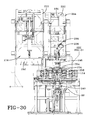
- the core gripper assembly 198 shown in FIG. 18 and in cross-section in FIG. 19 , is mounted to the moving sub-frame 224A.
- the core gripper assembly is designed to hold and transport the assembled tire building core comprising core 234 and spindle assemblies 236, 234, with or without a tire 230 on it, or the upper core spindle assembly 236 alone.
- the tip or frustro-conical nose 200 of the assembly 198 is tapered to match the tapered socket 238 in the spindle assembly 236. This frustro-conical nose and socket arrangement is the same one used on the bottom spindle clamp assembly 84 described above.
- a third pneumatic cylinder 208 located at the top, center of the shaft is used to drive a long rod 206 in the assembly center.
- This rod 206 actuates the latch at the center of the tire building core 234 that keeps the two halves of the core spindle together.
- Extending the cylinder 208 actuates the latch, which separates the two halves 236, 240 comprising the tire building core spindle.
- steps 10 and 11 above the segments may be removed using only the force provided by the ball screw 130 on the arm of each pin assembly 124, 127 of the lower core segment handling assembly 80.
- the lower unit 124, 127 would move a segment to the center, clear of the tire, where it would then be engaged by the upper unit 150. This would allow the next segment to be pushed to the center while the upper core segment handling assembly 150 is still placing the first segment on its storage pin 151.
- This alternate sequence would save several seconds from the total cycle time.
- the subject curing line 10 is commercially applicable to the manufacture of all types of tires as well as non-tire items such as bladders and sleeves.
- the line 10 is not material specific and is not limited only to the manufacture of rubber articles.
- the subject invention does not involve the conventional practice in the tire building art in which tires are manufactured on building drums that are flat when the tire components are applied and then form the tire carcass to shape that approximates that of the cured tire. Rather the invention accommodates tires built in their final, cured shape.
- the mold shapes the outside of the tire, and the core flanges provide a solid surface to maintain the inside shape of the tire during curing. The invention thereby provides the means to remove the solid core segments from within a cured tire.
Landscapes
- Engineering & Computer Science (AREA)
- Mechanical Engineering (AREA)
- Physics & Mathematics (AREA)
- Health & Medical Sciences (AREA)
- Oral & Maxillofacial Surgery (AREA)
- Thermal Sciences (AREA)
- Moulds For Moulding Plastics Or The Like (AREA)
- Heating, Cooling, Or Curing Plastics Or The Like In General (AREA)
- Tyre Moulding (AREA)
Applications Claiming Priority (1)
| Application Number | Priority Date | Filing Date | Title |
|---|---|---|---|
| US11/962,269 US7896632B2 (en) | 2007-12-21 | 2007-12-21 | Apparatus for disassembling a tire building core |
Publications (1)
| Publication Number | Publication Date |
|---|---|
| EP2072231A1 true EP2072231A1 (de) | 2009-06-24 |
Family
ID=40459766
Family Applications (1)
| Application Number | Title | Priority Date | Filing Date |
|---|---|---|---|
| EP08171819A Withdrawn EP2072231A1 (de) | 2007-12-21 | 2008-12-16 | Vorrichtung und Verfahren zur Demontage eines Reifenbaukerns |
Country Status (5)
| Country | Link |
|---|---|
| US (1) | US7896632B2 (de) |
| EP (1) | EP2072231A1 (de) |
| JP (1) | JP5317678B2 (de) |
| CN (1) | CN101462324B (de) |
| BR (1) | BRPI0805509A2 (de) |
Families Citing this family (3)
| Publication number | Priority date | Publication date | Assignee | Title |
|---|---|---|---|---|
| US7854603B2 (en) * | 2007-12-21 | 2010-12-21 | The Goodyear Tire & Rubber Company | Tire building core assembly and disassembly station |
| ITFI20120233A1 (it) * | 2012-10-29 | 2014-04-30 | Esanastri S R L | Dispositivo di micro-sfridatura di film plastici o in carta a uno o più strati autoadesivi, biadesivizzati o elettrostatici accoppiati con un liner di supporto antiaderente |
| JP6666638B2 (ja) * | 2017-12-25 | 2020-03-18 | 株式会社名機製作所 | 複合成形品用の射出成形機 |
Citations (9)
| Publication number | Priority date | Publication date | Assignee | Title |
|---|---|---|---|---|
| US4160007A (en) | 1976-09-13 | 1979-07-03 | Industrie Pirelli, S.P.A. | Method and improved apparatus for automatically handling a mold for tires with a rigid segmented core |
| US4279856A (en) | 1979-01-09 | 1981-07-21 | Bayer Aktiengesellschaft | Method and an apparatus for assembling and removing a segmented tire mold core in a tire mold |
| EP0893237A2 (de) | 1997-07-22 | 1999-01-27 | Bridgestone Corporation | Ein torusförmiger segmentierter Kern zur Herstellung von Luftreifen |
| US20030157209A1 (en) | 2000-02-21 | 2003-08-21 | Osvaldo Scarzello | Dismountable toroidal support for type manufacture |
| US20040207116A1 (en) | 2003-04-17 | 2004-10-21 | Jean-Claude Girard | Method for curing tires and a self-locking tire mold |
| US20050133149A1 (en) | 2003-12-19 | 2005-06-23 | Sieverding Mark A. | Single station tire curing method and apparatus |
| US20070125496A1 (en) | 2005-12-02 | 2007-06-07 | Lundell Dennis A | Tire building core latching and transport mechanism |
| US20070125497A1 (en) | 2005-12-02 | 2007-06-07 | Lundell Dennis A | Heated tire building core assembly and method |
| JP2007253414A (ja) | 2006-03-22 | 2007-10-04 | Yokohama Rubber Co Ltd:The | 中子分離取出し機構の脱着シリンダー装置 |
Family Cites Families (53)
| Publication number | Priority date | Publication date | Assignee | Title |
|---|---|---|---|---|
| US1179898A (en) * | 1915-04-22 | 1916-04-18 | Gutta Percha And Rubber Ltd | Tire-molding machine. |
| GB167073A (en) | 1920-07-15 | 1921-08-04 | Dunlop Rubber Co | Improvements in or relating to machines for making pneumatic tyre covers or casings |
| US1388255A (en) * | 1920-11-29 | 1921-08-23 | A corpo | |
| US1682620A (en) * | 1922-01-10 | 1928-08-28 | Budd Edward G Mfg Co | Apparatus for electrical vulcanizing |
| US2123586A (en) * | 1936-08-28 | 1938-07-12 | Nat Rubber Machinery Co | Tire building apparatus |
| GB549905A (en) | 1941-07-29 | 1942-12-14 | Dunlop Rubber Co | Improvements in or relating to tyre building machines and cores therefor |
| FR1480193A (fr) * | 1966-03-11 | 1967-05-12 | Dunlop Sa | Tambour dilatable permettant la confection d'enveloppes pour bandages pneumatiques |
| FR1510912A (fr) * | 1966-11-15 | 1968-01-26 | Tambour de galbage pour la confection d'enveloppes de pneumatiques | |
| DE2002294A1 (de) | 1970-01-20 | 1971-07-29 | Krupp Gmbh | Bombiertrommel |
| US3684621A (en) * | 1970-06-18 | 1972-08-15 | Nat Standard Co | Tire building drum |
| FR2125642A5 (de) * | 1971-02-15 | 1972-09-29 | Gazuit Georges | |
| US3868203A (en) * | 1971-05-17 | 1975-02-25 | Nrm Corp | Tire molding machine |
| US3833445A (en) * | 1972-01-14 | 1974-09-03 | Nat Standard Co | Tire building apparatus for building tires |
| DE2409586B2 (de) * | 1974-02-28 | 1976-12-09 | Zusatz in: 25 05 486 Continental Gummi-Werke AG, 3000 Hannover | Vorrichtung zum ueberfuehren einer mit kernringen belegten karkasse fuer luftreifenrohlinge |
| US4075275A (en) * | 1974-04-22 | 1978-02-21 | Bridgestone Tire Company Limited | Methods of casting pneumatic tires |
| IT1038996B (it) * | 1975-06-13 | 1979-11-30 | Pirelli | Stampo per pneumatico e relativo metodo e dispositivo di manipolazione |
| FR2314821A1 (fr) | 1975-06-20 | 1977-01-14 | Zelant Gazuit | Tambour de confection de pneus a carcasse radiale |
| AT339757B (de) * | 1975-10-03 | 1977-11-10 | Polyair Maschinenbau Gmbh | Vorrichtung zum giessen oder spritzen von fahrzeugreifen |
| US4045277A (en) * | 1976-05-11 | 1977-08-30 | Uniroyal, Inc. | Pneumatic tire building drum |
| US4083672A (en) * | 1977-03-28 | 1978-04-11 | The Firestone Tire & Rubber Company | Automatic hub and apparatus for disassembly of the hub |
| IT1086200B (it) * | 1977-05-19 | 1985-05-28 | Pirelli | Procedimento e relativo impianto per fabbricare pneumatici con stampaggio in piu' fasi |
| US4211592A (en) * | 1978-08-14 | 1980-07-08 | Caterpillar Tractor Co. | Method of building a closed tube-tire |
| WO1982000017A1 (en) | 1980-06-25 | 1982-01-07 | Dennis R | Safety device for a workpiece holder |
| FR2597783B1 (fr) * | 1986-04-25 | 1988-08-26 | Michelin & Cie | Moule rigide pour le moulage et la vulcanisation de pneumatiques |
| IT1189673B (it) * | 1986-05-20 | 1988-02-04 | Firestone Int Dev Spa | Impianto di vulcanizzazione di pneumatici |
| IT1189672B (it) * | 1986-05-20 | 1988-02-04 | Firestone Int Dev Spa | Metodo per la realizzazione a caldo di pneumatici |
| US5201975A (en) * | 1987-11-13 | 1993-04-13 | Bridgestone/Firestone Inc. | Tire manufacture |
| IT1240509B (it) | 1990-07-27 | 1993-12-17 | Firestone Int Dev Spa | Metodo di preriscaldamento, vulcanizzazione e stabilizzazione di pneumatici di veicoli |
| US6406576B1 (en) * | 1991-12-20 | 2002-06-18 | 3M Innovative Properties Company | Method of making coated abrasive belt with an endless, seamless backing |
| IT1259599B (it) * | 1992-07-01 | 1996-03-20 | Firestone Int Dev Spa | Metodo per la realizzazione di pneumatici di veicoli stradali. |
| FR2708888A1 (fr) * | 1993-08-09 | 1995-02-17 | Sedepro | Procédé et appareil de vulcanisation de pneumatiques. |
| FR2715602A1 (fr) * | 1994-02-02 | 1995-08-04 | Sedepro | Assemblage et vulcanisation de pneumatiques. |
| FR2720326A1 (fr) * | 1994-05-27 | 1995-12-01 | Sedepro | Assemblage et vulcanisation de pneumatique. |
| FR2749536A1 (fr) * | 1996-06-11 | 1997-12-12 | Michelin & Cie | Tambour d'assemblage d'un pneumatique |
| JP3751128B2 (ja) * | 1997-08-08 | 2006-03-01 | 株式会社ブリヂストン | タイヤ製造用内型の取外し装置 |
| US6318432B1 (en) * | 1997-11-28 | 2001-11-20 | Pirelli Pneumatici S.P.A. | Tire for vehicle wheels |
| DE19800289C2 (de) | 1998-01-07 | 2000-03-16 | Continental Ag | Verfahren zur Herstellung von Luftreifen |
| JP3954195B2 (ja) | 1998-04-06 | 2007-08-08 | 株式会社ブリヂストン | タイヤ成型装置およびそれを用いたタイヤ成型方法 |
| US6250356B1 (en) * | 1998-04-28 | 2001-06-26 | Compagnie Géńerale des Etablissements Michelin - Michelin & Cie. | Assembly drum and method for the manufacture of tires |
| JPH11320567A (ja) | 1998-05-11 | 1999-11-24 | Bridgestone Corp | タイヤ加硫装置および加硫方法 |
| US6183831B1 (en) * | 1998-08-20 | 2001-02-06 | Intevac, Inc. | Hard disk vapor lube |
| DE19905643C2 (de) | 1999-02-11 | 2001-05-03 | Continental Ag | Verfahren zur Herstellung eines Luftreifens |
| JP4001441B2 (ja) | 1999-06-18 | 2007-10-31 | 横浜ゴム株式会社 | 電磁誘導加硫機の加熱制御方法 |
| JP2001079850A (ja) | 1999-07-15 | 2001-03-27 | Yokohama Rubber Co Ltd:The | タイヤ加硫方法及びその装置 |
| JP3668073B2 (ja) | 1999-09-29 | 2005-07-06 | 株式会社神戸製鋼所 | タイヤ製造方法 |
| TR200401666T4 (tr) * | 2000-02-21 | 2004-08-23 | Pirelli Pneumatici S.P.A. | Lastik imalatı için sökülebilir toroidal destek. |
| WO2001062480A1 (en) * | 2000-02-21 | 2001-08-30 | Pirelli Pneumatici S.P.A. | Method of removing a dismountable toroidal support from a cured tyre |
| JP2002096403A (ja) | 2000-09-21 | 2002-04-02 | Yokohama Rubber Co Ltd:The | タイヤ製造方法及びその装置 |
| DE60108520T2 (de) | 2000-12-06 | 2006-01-12 | Pirelli Pneumatici Società per Azioni | Verfahren zur herstellung; formung und vulkanisierung von reifen für fahrzeugräder |
| JP2002307440A (ja) * | 2001-04-10 | 2002-10-23 | Bridgestone Corp | タイヤ製造用コアのセグメント取出し方法および取出し組立方法、ならびにそれらの方法を実施するために使用する装置 |
| CN101298192B (zh) | 2002-06-05 | 2012-07-04 | 株式会社普利司通 | 轮胎制造方法及轮胎成型鼓 |
| JP4275476B2 (ja) | 2003-07-24 | 2009-06-10 | 株式会社ブリヂストン | タイヤ製造用コア |
| US7712504B2 (en) * | 2005-06-17 | 2010-05-11 | Michelin Recherche Et Technique S.A. | Machine for assembling and vulcanising tires |
-
2007
- 2007-12-21 US US11/962,269 patent/US7896632B2/en not_active Expired - Fee Related
-
2008
- 2008-12-16 EP EP08171819A patent/EP2072231A1/de not_active Withdrawn
- 2008-12-18 BR BRPI0805509-2A patent/BRPI0805509A2/pt not_active IP Right Cessation
- 2008-12-22 JP JP2008326370A patent/JP5317678B2/ja not_active Expired - Fee Related
- 2008-12-22 CN CN200810185374XA patent/CN101462324B/zh not_active Expired - Fee Related
Patent Citations (9)
| Publication number | Priority date | Publication date | Assignee | Title |
|---|---|---|---|---|
| US4160007A (en) | 1976-09-13 | 1979-07-03 | Industrie Pirelli, S.P.A. | Method and improved apparatus for automatically handling a mold for tires with a rigid segmented core |
| US4279856A (en) | 1979-01-09 | 1981-07-21 | Bayer Aktiengesellschaft | Method and an apparatus for assembling and removing a segmented tire mold core in a tire mold |
| EP0893237A2 (de) | 1997-07-22 | 1999-01-27 | Bridgestone Corporation | Ein torusförmiger segmentierter Kern zur Herstellung von Luftreifen |
| US20030157209A1 (en) | 2000-02-21 | 2003-08-21 | Osvaldo Scarzello | Dismountable toroidal support for type manufacture |
| US20040207116A1 (en) | 2003-04-17 | 2004-10-21 | Jean-Claude Girard | Method for curing tires and a self-locking tire mold |
| US20050133149A1 (en) | 2003-12-19 | 2005-06-23 | Sieverding Mark A. | Single station tire curing method and apparatus |
| US20070125496A1 (en) | 2005-12-02 | 2007-06-07 | Lundell Dennis A | Tire building core latching and transport mechanism |
| US20070125497A1 (en) | 2005-12-02 | 2007-06-07 | Lundell Dennis A | Heated tire building core assembly and method |
| JP2007253414A (ja) | 2006-03-22 | 2007-10-04 | Yokohama Rubber Co Ltd:The | 中子分離取出し機構の脱着シリンダー装置 |
Also Published As
| Publication number | Publication date |
|---|---|
| BRPI0805509A2 (pt) | 2009-12-01 |
| JP5317678B2 (ja) | 2013-10-16 |
| US7896632B2 (en) | 2011-03-01 |
| CN101462324A (zh) | 2009-06-24 |
| CN101462324B (zh) | 2012-11-14 |
| JP2009149093A (ja) | 2009-07-09 |
| US20090159207A1 (en) | 2009-06-25 |
Similar Documents
| Publication | Publication Date | Title |
|---|---|---|
| EP2072237B1 (de) | System und Verfahren für den Auf- und Abbau einer Reifenvulkanisierform | |
| EP2072227B1 (de) | Reifenabladevorrichtung und Verfahren in einer Vulkanisiereinrichtung | |
| EP2072226A1 (de) | Ladevorrichtung und Verfahren für den Auf- und Abbau einer Reifenhärtungsform | |
| EP2072238B1 (de) | Vorrichtung und Verfahren zum Aufbau, Abbau und Aufbewahrung eines Reifenaufbaukerns | |
| EP2072228B1 (de) | Reifenbaukernmanipuliervorrichtung und Verfahren | |
| EP2072229B1 (de) | Reifenbaukernauf- und Abbaustation und Verfahren | |
| US7896632B2 (en) | Apparatus for disassembling a tire building core | |
| US7910043B2 (en) | Tire building and cure station coupling apparatus and method | |
| EP2072239B1 (de) | Reifenbaukernsegmentmanipuliervorrichtung und Verfahren |
Legal Events
| Date | Code | Title | Description |
|---|---|---|---|
| PUAI | Public reference made under article 153(3) epc to a published international application that has entered the european phase |
Free format text: ORIGINAL CODE: 0009012 |
|
| AK | Designated contracting states |
Kind code of ref document: A1 Designated state(s): AT BE BG CH CY CZ DE DK EE ES FI FR GB GR HR HU IE IS IT LI LT LU LV MC MT NL NO PL PT RO SE SI SK TR |
|
| AX | Request for extension of the european patent |
Extension state: AL BA MK RS |
|
| 17P | Request for examination filed |
Effective date: 20091228 |
|
| AKX | Designation fees paid |
Designated state(s): DE ES FR GB IT |
|
| 17Q | First examination report despatched |
Effective date: 20100126 |
|
| STAA | Information on the status of an ep patent application or granted ep patent |
Free format text: STATUS: THE APPLICATION IS DEEMED TO BE WITHDRAWN |
|
| 18D | Application deemed to be withdrawn |
Effective date: 20130603 |