EP1375111B1 - Segmentiertes Formwerkzeug, insbesondere zum Herstellen eines Lufteinlasses ohne Verbindungslasche - Google Patents
Segmentiertes Formwerkzeug, insbesondere zum Herstellen eines Lufteinlasses ohne Verbindungslasche Download PDFInfo
- Publication number
- EP1375111B1 EP1375111B1 EP03362007A EP03362007A EP1375111B1 EP 1375111 B1 EP1375111 B1 EP 1375111B1 EP 03362007 A EP03362007 A EP 03362007A EP 03362007 A EP03362007 A EP 03362007A EP 1375111 B1 EP1375111 B1 EP 1375111B1
- Authority
- EP
- European Patent Office
- Prior art keywords
- sectors
- chuck
- sector
- key
- locking
- Prior art date
- Legal status (The legal status is an assumption and is not a legal conclusion. Google has not performed a legal analysis and makes no representation as to the accuracy of the status listed.)
- Expired - Lifetime
Links
- 238000004519 manufacturing process Methods 0.000 title description 2
- 238000000465 moulding Methods 0.000 claims description 16
- 230000007246 mechanism Effects 0.000 abstract description 3
- 230000037431 insertion Effects 0.000 abstract 2
- 238000003780 insertion Methods 0.000 abstract 2
- KWGRBVOPPLSCSI-WPRPVWTQSA-N (-)-ephedrine Chemical compound CN[C@@H](C)[C@H](O)C1=CC=CC=C1 KWGRBVOPPLSCSI-WPRPVWTQSA-N 0.000 description 25
- 238000006073 displacement reaction Methods 0.000 description 5
- 238000006116 polymerization reaction Methods 0.000 description 4
- 238000000034 method Methods 0.000 description 2
- 230000004048 modification Effects 0.000 description 2
- 238000012986 modification Methods 0.000 description 2
- 238000004804 winding Methods 0.000 description 2
- 229910000831 Steel Inorganic materials 0.000 description 1
- 230000009471 action Effects 0.000 description 1
- 230000001413 cellular effect Effects 0.000 description 1
- 230000000295 complement effect Effects 0.000 description 1
- 239000000470 constituent Substances 0.000 description 1
- 238000010411 cooking Methods 0.000 description 1
- 230000006378 damage Effects 0.000 description 1
- 238000013016 damping Methods 0.000 description 1
- 238000005516 engineering process Methods 0.000 description 1
- 235000021183 entrée Nutrition 0.000 description 1
- 230000002093 peripheral effect Effects 0.000 description 1
- 230000008569 process Effects 0.000 description 1
- 239000011347 resin Substances 0.000 description 1
- 229920005989 resin Polymers 0.000 description 1
- 230000000284 resting effect Effects 0.000 description 1
- 239000010959 steel Substances 0.000 description 1
- 238000003466 welding Methods 0.000 description 1
Images



Classifications
-
- F—MECHANICAL ENGINEERING; LIGHTING; HEATING; WEAPONS; BLASTING
- F02—COMBUSTION ENGINES; HOT-GAS OR COMBUSTION-PRODUCT ENGINE PLANTS
- F02C—GAS-TURBINE PLANTS; AIR INTAKES FOR JET-PROPULSION PLANTS; CONTROLLING FUEL SUPPLY IN AIR-BREATHING JET-PROPULSION PLANTS
- F02C7/00—Features, components parts, details or accessories, not provided for in, or of interest apart form groups F02C1/00 - F02C6/00; Air intakes for jet-propulsion plants
- F02C7/04—Air intakes for gas-turbine plants or jet-propulsion plants
-
- B—PERFORMING OPERATIONS; TRANSPORTING
- B29—WORKING OF PLASTICS; WORKING OF SUBSTANCES IN A PLASTIC STATE IN GENERAL
- B29C—SHAPING OR JOINING OF PLASTICS; SHAPING OF MATERIAL IN A PLASTIC STATE, NOT OTHERWISE PROVIDED FOR; AFTER-TREATMENT OF THE SHAPED PRODUCTS, e.g. REPAIRING
- B29C53/00—Shaping by bending, folding, twisting, straightening or flattening; Apparatus therefor
- B29C53/80—Component parts, details or accessories; Auxiliary operations
- B29C53/82—Cores or mandrels
- B29C53/821—Mandrels especially adapted for winding and joining
- B29C53/824—Mandrels especially adapted for winding and joining collapsible, e.g. elastic or inflatable; with removable parts, e.g. for regular shaped, straight tubular articles
-
- B—PERFORMING OPERATIONS; TRANSPORTING
- B64—AIRCRAFT; AVIATION; COSMONAUTICS
- B64D—EQUIPMENT FOR FITTING IN OR TO AIRCRAFT; FLIGHT SUITS; PARACHUTES; ARRANGEMENT OR MOUNTING OF POWER PLANTS OR PROPULSION TRANSMISSIONS IN AIRCRAFT
- B64D33/00—Arrangement in aircraft of power plant parts or auxiliaries not otherwise provided for
- B64D33/02—Arrangement in aircraft of power plant parts or auxiliaries not otherwise provided for of combustion air intakes
-
- B—PERFORMING OPERATIONS; TRANSPORTING
- B64—AIRCRAFT; AVIATION; COSMONAUTICS
- B64F—GROUND OR AIRCRAFT-CARRIER-DECK INSTALLATIONS SPECIALLY ADAPTED FOR USE IN CONNECTION WITH AIRCRAFT; DESIGNING, MANUFACTURING, ASSEMBLING, CLEANING, MAINTAINING OR REPAIRING AIRCRAFT, NOT OTHERWISE PROVIDED FOR; HANDLING, TRANSPORTING, TESTING OR INSPECTING AIRCRAFT COMPONENTS, NOT OTHERWISE PROVIDED FOR
- B64F5/00—Designing, manufacturing, assembling, cleaning, maintaining or repairing aircraft, not otherwise provided for; Handling, transporting, testing or inspecting aircraft components, not otherwise provided for
- B64F5/10—Manufacturing or assembling aircraft, e.g. jigs therefor
-
- F—MECHANICAL ENGINEERING; LIGHTING; HEATING; WEAPONS; BLASTING
- F01—MACHINES OR ENGINES IN GENERAL; ENGINE PLANTS IN GENERAL; STEAM ENGINES
- F01D—NON-POSITIVE DISPLACEMENT MACHINES OR ENGINES, e.g. STEAM TURBINES
- F01D25/00—Component parts, details, or accessories, not provided for in, or of interest apart from, other groups
- F01D25/28—Supporting or mounting arrangements, e.g. for turbine casing
- F01D25/285—Temporary support structures, e.g. for testing, assembling, installing, repairing; Assembly methods using such structures
-
- B—PERFORMING OPERATIONS; TRANSPORTING
- B29—WORKING OF PLASTICS; WORKING OF SUBSTANCES IN A PLASTIC STATE IN GENERAL
- B29L—INDEXING SCHEME ASSOCIATED WITH SUBCLASS B29C, RELATING TO PARTICULAR ARTICLES
- B29L2031/00—Other particular articles
- B29L2031/08—Blades for rotors, stators, fans, turbines or the like, e.g. screw propellers
- B29L2031/087—Propellers
-
- F—MECHANICAL ENGINEERING; LIGHTING; HEATING; WEAPONS; BLASTING
- F05—INDEXING SCHEMES RELATING TO ENGINES OR PUMPS IN VARIOUS SUBCLASSES OF CLASSES F01-F04
- F05D—INDEXING SCHEME FOR ASPECTS RELATING TO NON-POSITIVE-DISPLACEMENT MACHINES OR ENGINES, GAS-TURBINES OR JET-PROPULSION PLANTS
- F05D2230/00—Manufacture
- F05D2230/60—Assembly methods
- F05D2230/64—Assembly methods using positioning or alignment devices for aligning or centring, e.g. pins
Definitions
- the present invention relates to the manufacture of nacelle air intakes containing the powertrain, in particular a jet engine, of aircraft.
- the nacelle has a substantially annular section and defines between it and the central part of the engine a so-called annular fan duct.
- the wall of the nacelle defining this fan duct is acoustically treated and consists of a sandwich formed of a central alveolar core flanked, on the fan duct side, with an acoustically resistive layer and, on the other side, with a total reflector.
- This wall is usually formed of several sectors or segments, generally four or three, abutting by splicing to form a substantially annular conduit.
- the documents DE 2 259 690 and U.S.-A-1,835,986 describe tools having a mandrel provided with sectors spliced abutting to form a substantially annular conduit, articulated retractable towards the center of said mandrel and a sector called key sector independent of the other two sectors and insertable between them, so, by finger-jointing , to determine, by their outer face, a continuous surface corresponding to the inner face of the air inlet and means for locking in abutment said sectors operated by a solitary control device of the tools.
- the present invention improves this type of tooling by proposing means for making the mandrel self-supporting and provides a detachable control device of the mandrel.
- the present invention specifically aims to provide a key molding tool for the particular embodiment of air inlet without splint.
- an air inlet without a splice is formed of a substantially tubular panel consisting of a sandwich comprising a cellular core core, a total reflector and a resistive layer disposed on the inner face of the panel, said face internal having no connection or splint that can disrupt the acoustic damping of the panel.
- Such a mandrel once shaped, ie with the abutting and locked sector panels and provided with its flanges, can be placed horizontally on a rotary drive device for example for placement by draping, winding or wrapping the constituent element or elements of the acoustically resistive layer of a channel panel; monobloc blower without splint, then the establishment of other components of the panel.
- the mandrel is recovered and placed in an oven or in an autoclave, after removal or not of the flanges.
- the flanges are (possibly) put back on the mandrel which is then placed in a vertical position on the assembly / disassembly of the mandrel.
- the device is, after unlocking the key sector, actuated in a manner, in the first place, to translate the key sector in translation inwards, then, in the second place, to pivot inwardly the two articulated sectors of the way to separate these three sectors of the air intake panel made, which can then be easily removed.
- the device can then be operated by an inverse process to reconstitute a shaped mandrel to make another panel.
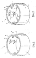
- FIG. 1 to 3 schematically shows a key mandrel 1 according to the invention, respectively in its molding configuration ( Figures 1 and 2 ) and in its demolding configuration ( figure 3 ).
- the mandrel 1 is generally tubular and consists of four sections or sectors, namely a so-called fixed sector 2 on either side of which are associated two sectors 3, identical, said articulated sectors because they are connected to the sector fixes 2 each by a pair of hinges 4.
- the fourth sector 5, referred to as key sector, is an independent sector that is interposed between the two articulated sectors 3. It is lockable in place on the two adjacent sectors 3 by locks 6 ( figure 2 ) integral with the key sector 5 and cooperating with latches 7 fixed on the sectors 3 opposite the lock bolts 6.
- the sectors 2, 3, 5, in the molding position of the mandrel 1, define an external face which corresponds to the internal wall in contact with the air flow which enters the fan duct, the inlet panel of air to achieve.
- the setting in mold release configuration ( figure 3 ) of the mandrel is effected by an inward withdrawal of the key sector 5, after unlocking the locks 6, and then folding inward articulated sectors 3 by rotation about the axis of the hinges 4.
- the necessary tools This operation will be described later with reference to Figures 8 to 11 .
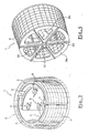
- the figure 4 represents the chuck 1 of Figures 1 and 2 on which was installed for example by winding, wrapping or draping a resistive layer 8 constituting one of the elements of an air inlet panel without splice in the sense defined above.
- the mandrel 1 is sandwiched between two end flanges 9a, 9b, connected by ties 10, the flanges being supported by their periphery on the edge of the sectors.
- bushings 11 for transporting the mandrel and placing it on a rotary drive device (not shown) of the mandrel 1 around its axis arranged for example horizontally.
- the figure 5 represents the mandrel 1 of the figure 4 , removed from its flanges 9a, 9b and in place on a cradle 12 for passage in an oven or autoclave, for example, to polymerize the resin of the resistive layer 8.
- the mandrel 1 rests on peripheral pads 13. It is however, note that the mandrel 1 can go into an oven or autoclave without being cleared beforehand of its flanges.
- a fixed sector 2 an articulated sector 3 and a key sector 5, all made up of a frame formed of uprights parallel 14 connected to each other, on the inside, by parallel bent crosspieces 15 and, on the outside, by a thin veil 16 whose outer face defines the molding surface of the mandrel.
- the locks 6 of the key sector 5 are fixed on reinforced lateral uprights 14 'and cooperating with strikers 7 also fixed on reinforced lateral uprights 14 "of the articulated sector 3.
- the figure 8 is a partial top view of the structure of the figure 6 at the junction between key sector 5 and one of the articulated sectors 3.
- the latch 6 is carried by a plate 18 itself fixed to the lateral upright 14 'of the key sector 5.
- the latch bolt 19 passes through the wall of the upright 14 'and that of the lateral upright 14 "of the sector 3 and engages the striker 7.
- the bolt 19 is moved using means described below with reference to the figure 11 .
- FIGs 9 to 12 represent an embodiment of the means able to put the mandrel 1 in one or other of the molding configurations ( figure 1 ) and demolding ( figure 3 ).
- These means comprise a steel tubular frame 20 of generally octagonal shape, defining a first path of displacement 21 diametral to the octagonal structure, flanked by two symmetrical displacement paths 22, converging substantially towards one of the ends of said first path 21.
- the path 21 is defined by two parallel horizontal beams 23.
- a crosspiece 24 carrying two pins 25 for supporting and center in the vertical position of the fixed sector 2 of the mandrel.
- sockets 26 In the lower part of sector 2 ( figure 6 ) are arranged at the ends of two uprights 14, sockets 26 likely to come engage on the counters 25, as illustrated by the figure 10 .
- a carriage 29 On the rails 27 circulates, by means of shoes 28 ( figure 12 ), a carriage 29 whose end (outer side) carries a cross member 30 provided with two pins 31 of support and centering, similar to the pins 25 and for receiving sockets 32, similar to the sleeves 26, provided at the lower end ( figure 6 ) of amounts 14 of the key sector 5.
- the carriage 29 is moved by a screw 33 driving a nut 34 secured to the carriage 29.
- the screw 33 pivots in the frame 20 and is provided at its outer end with a bevel gear 35 for control of the screw either manually or by a pneumatic screwdriver.
- the carriage 29 carries a bracket 36 supporting two devices for actuating the two pairs of locks 6.
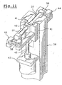
- figure 11 shows in more detail the actuating device of the upper pair of locks of the key sector 5.
- Each device comprises a toggle-type control linkage consisting of two lateral references 37 whose hook-shaped ends 38 cooperate with the complementary ends 39 (FIG. figures 6 and 8 ) bolts 19 locks 6.
- the latches 37 are articulated on a yoke 40 movable vertically in guiding slides 41 fixed to the bracket 36, under the action of the rod 42 of a cylinder 43 also attached to the bracket.
- the ends 38 of the references 37 are held by guides 44 integral with the bracket 36.
- Each path 22 comprises two parallel beams carrying two rails 45 on which slides via a carriage 46 moved, such as the carriage 29, with a screw 47 provided with an angle gear 48.
- Each carriage 46 carries a driving and guiding pin 49 which can be received in a suitable groove (not shown) formed at the lower end of each articulated sector 3.
- the mandrel 1 is partially represented in the molding position, in line with its rest position on the frame 20.
- the mandrel is simply placed on the pins 25 (fixed sector 2), on the pins 31 (sector-key 5) and on the pins 49 (articulated sectors 3), the carriages 29 and 46 being in one of their two extreme positions on their respective travel path 21 and 22.
- the unlocking of the locks 6 is controlled by retracting the rod of the cylinders 43, 43 ', then the carriage 29 is moved towards the center of the frame 20, the carriages 46 still being stationary and locked.
- the screws 33 and 47 are preferably controlled automatically by a control device (not shown) synchronizing the movements of the carriages 29, 46 to accelerate the operation, but said screws 33, 47 can be manually controlled using cranks for example .
- the mandrel 1 is placed back on the frame 20, ie after polymerization of the resistive layer in order to recover the latter, the other elements of the sandwich defining the air inlet panel being put in place according to other techniques, either after polymerization. final said sandwich, to recover the panel for its completion, all the elements of the panel being placed on the starting chuck.
- the mandrel according to the invention may comprise a number of different sectors of four, namely at least three sectors, or a greater number , including five sectors.
- two sectors S1 and S2 are articulated one on the other about a fixed axis A of rotation and the third sector S3 forming key sector is independent and movable and can be inserted between the two others in the deployed position for constituting by butting a continuous surface corresponding to the inner face of an air inlet.
- the key sector S3 is first moved towards the center of the mandrel (position S'3), then the sectors S1, S2 are folded towards each other (positions S'1, S ' 2).
- sectors S4 to S7 are butted.
- the articulated sectors S4 to S7 are first folded towards the center of the mandrel as illustrated in S'4 to S'7 on the figure 14 then the key sector S8 is moved towards the center of the mandrel in S'8.
- the mandrel comprises an independent and movable key sector, the other sectors being hinged together or movable so as to retract towards the inside of the mandrel.
Landscapes
- Engineering & Computer Science (AREA)
- Chemical & Material Sciences (AREA)
- Combustion & Propulsion (AREA)
- Mechanical Engineering (AREA)
- Manufacturing & Machinery (AREA)
- Aviation & Aerospace Engineering (AREA)
- General Engineering & Computer Science (AREA)
- Transportation (AREA)
- Moulds For Moulding Plastics Or The Like (AREA)
- Moulding By Coating Moulds (AREA)
- Blow-Moulding Or Thermoforming Of Plastics Or The Like (AREA)
- Portable Nailing Machines And Staplers (AREA)
- Scissors And Nippers (AREA)
Claims (8)
- Segmentiertes Formwerkzeug zur Herstellung insbesondere von einem im Wesentlichen rohrförmigen Lufteinlass ohne Verbindungslasche mit:- einem Futter mit Schlüssel, das mindestens drei Segmente in Form von Platten aufweist, insbesondere mindestens zwei gelenkige Segmente (S1, S2), die in das Zentrum des Spannfutters einziehbar sind, und ein Schlüsselsegment (S3) genanntes Segment, das von den beiden anderen Segmenten unabhängig ist und zwischen beiden eingeschoben werden kann, so dass sie so zusammengefügt sind, dass sie durch ihre Außenseite eine durchgehende Fläche bestimmen, die der Innenseite eines Lufteinlasses entspricht;- Mitteln zum Verriegeln der Segmente (S1 bis S3) in der zusammengefügten Position;- und einer Steuervorrichtung zur Bewegung der beweglichen Segmente relativ zueinander, um sie entweder in eine Position zum Formen durch Zusammenfügung der Segmente zu bringen oder in eine Position zum Aus-der-Form-nehmen (S'1 bis S'3) durch Zurückziehen der Segmente zum Inneren des Futters, dadurch gekennzeichnet, dass:- das Futter ein selbsttragendes Futter ist und die Steuervorrichtung vom Futter lösbar ist.
- Werkzeug nach Anspruch 1, dadurch gekennzeichnet, dass es aufweist:- ein Futter mit Schlüssel (1) mit vier Segmenten, nämlich einem festen Segment (2), flankiert von zwei anderen symmetrischen und mit dem festen Segment (2) gelenkig verbundenen Segmenten (3) und einem von den anderen Segmenten unabhängigen Schlüsselsegment (5), das zwischen den beiden gelenkigen Segmenten (3) eingeschoben werden kann, und Mittel (6, 7) zur Verriegelung in der zusammengefügten Position der Segmente, wodurch das Futter selbsttragend wird;- eine Steuervorrichtung (29 bis 35; 45 bis 49) zur Bewegung Segemente (3, 5) relativ zueinander, um sie entweder in eine Position zum Formen durch Zusammenfügung der Segmente (2, 3, 5) oder in eine Position zum Aus-der-Formnehmen durch Zurückziehen der drei beweglichen Segmente (3, 5) zum Inneren des Spannfutters (1) zu bringen, wobei die Steuervorrichtung vom Futter lösbar ist, und- Mitteln zum Transport und der Versetzung des Futters (1) in Drehung in seiner Position zum Formen, bestehend aus zwei abnehmbaren Flanschen (9a, 9b), die an die beiden Enden des Futters anpassbar sind, wobei die Flansche über Befestigungsbolzen (10) verbunden sind und in ihrem Inneren mit einer Buchse (11) oder ähnlichem versehen sind zur Befestigung von Antriebsmitteln des Futters im Rotationsinn um seine Achse.
- Werkzeug nach Anspruch 2, dadurch gekennzeichnet, dass die Steuervorrichtung zur Verschiebung der Segmente (3, 5) besteht aus einer Struktur (20) zur Aufnahme des Futters in axial vertikaler Position, die aufweist:- erste feststehende Mittel (24, 25), auf denen das feste Segment (2) ruht,- zweite bewegliche Mittel (29 bis 35), auf denen das Schlüsselsegment (5) ruht, und die entgegengesetzt zum Futter verschiebbar sind,- und dritte und vierte bewegliche Mittel (45 bis 49) zur Stützung der beiden gelenkigen Segmente (3), wobei die Mittel jeweils einen beweglichen Schlitten (46) innerhalb des Futters aufweisen und ein Antriebsmittel (49) tragen, auf dem eines der beiden gelenkigen Segmente (3) ruht.
- Werkzeug nach Anspruch 2 oder 3, dadurch gekennzeichnet, dass die gelenkigen Segmente (3) und das Schlüsselsegment (5) mit Mitteln (6,7) zur Verriegelung der Segmente in der Anschlagsposition versehen sind.
- Werkzeug nach Anspruch 3 oder 4, dadurch gekennzeichnet, dass die zweiten Mittel (29 bis 35) Mittel (36 bis 44) zur Steuerung der genannten Verriegelungsmittel (6, 7) aufweisen.
- Werkzeug nach Anspruch 5, dadurch gekennzeichnet, dass die Verriegelungsmittel aus zwei Paaren von Riegeln (19) bestehen, die translatorisch beweglich sind, um die beiden gegenüberliegenden Abschnitte (14', 14") zweier benachbarter Segmente (3, 5), die aneinander anliegen sollen, zu verbinden oder zu lösen, und dass die Mittel zum Steuern der Verriegelungsmittel aus einem Paar Kniehebel (37, 40) zur Steuerung der Translation der Riegel bestehen.
- Werkzeug nach einem der vorhergehenden Ansprüche, dadurch gekennzeichnet, dass die Steuervorrichtung einen automatische Vorrichtung ist.
- Werkzeug nach einem der vorhergehenden Ansprüche, dadurch gekennzeichnet, dass das Futter derart gestaltet ist, dass, wenn es in Form gebracht ist, nach Arretierung der Riegel (6) die Steuervorrichtungen (37, 38) von den Riegeln abnehmbar sind und das vom Rahmen (20) abgenomme Futter (1) dank einer Verriegelung des Schlüsselsegments (5) selbsttragend und geeignet ist, mit Transport- und Drehflanschen (9a, 9b) versehen zu werden.
Applications Claiming Priority (2)
| Application Number | Priority Date | Filing Date | Title |
|---|---|---|---|
| FR0208014A FR2841494B1 (fr) | 2002-06-27 | 2002-06-27 | Outillage de moulage a clef notamment pour la realisation d'entree d'air sans eclisse |
| FR0208014 | 2002-06-27 |
Publications (3)
| Publication Number | Publication Date |
|---|---|
| EP1375111A2 EP1375111A2 (de) | 2004-01-02 |
| EP1375111A3 EP1375111A3 (de) | 2007-11-14 |
| EP1375111B1 true EP1375111B1 (de) | 2008-12-24 |
Family
ID=29717117
Family Applications (1)
| Application Number | Title | Priority Date | Filing Date |
|---|---|---|---|
| EP03362007A Expired - Lifetime EP1375111B1 (de) | 2002-06-27 | 2003-06-11 | Segmentiertes Formwerkzeug, insbesondere zum Herstellen eines Lufteinlasses ohne Verbindungslasche |
Country Status (6)
| Country | Link |
|---|---|
| US (1) | US7125237B2 (de) |
| EP (1) | EP1375111B1 (de) |
| AT (1) | ATE418436T1 (de) |
| CA (1) | CA2430175A1 (de) |
| DE (1) | DE60325444D1 (de) |
| FR (1) | FR2841494B1 (de) |
Families Citing this family (21)
| Publication number | Priority date | Publication date | Assignee | Title |
|---|---|---|---|---|
| US7707708B2 (en) * | 2005-09-21 | 2010-05-04 | Rohr, Inc. | Apparatus for making a tubular composite structure |
| ITTO20060463A1 (it) * | 2006-06-23 | 2007-12-24 | Alenia Aeronautica Spa | Apparecchiatura e procedimento per la fabbricazione di un tronco di fusoliera |
| US8245750B2 (en) * | 2008-02-11 | 2012-08-21 | Rohr, Inc. | Segmented mandrel for high temperature bonding of metallic axisymmetric shells having complex curvatures |
| US7640961B2 (en) | 2008-03-21 | 2010-01-05 | Rohr, Inc. | Apparatus and method for making a tubular composite barrel |
| GB0810870D0 (en) * | 2008-06-13 | 2008-07-23 | Advanced Composite Components | Tooling |
| US8025499B2 (en) | 2008-11-03 | 2011-09-27 | Rohr, Inc. | Multi-segment tool and method for composite formation |
| JP5576651B2 (ja) | 2009-12-25 | 2014-08-20 | 川崎重工業株式会社 | 複合材料構造物製造用マンドレルの組立方法およびマンドレルの組立装置 |
| JP5576652B2 (ja) * | 2009-12-25 | 2014-08-20 | 川崎重工業株式会社 | 複合材料構造物製造用マンドレルの分解方法およびマンドレルの分解装置 |
| RU2482028C1 (ru) * | 2011-12-21 | 2013-05-20 | Открытое акционерное общество "Национальный институт авиационных технологий" (ОАО НИАТ) | Стапель для сборки воздухозаборника двигателя летательного аппарата |
| ITTO20120285A1 (it) * | 2012-03-30 | 2013-10-01 | Alenia Aermacchi Spa | Sistema bloccaggio settori appartenenti ad un dispositivo per la realizzazione di una sezione di fusoliera di un aereo |
| FR2991628A1 (fr) * | 2012-06-12 | 2013-12-13 | Aircelle Sa | Ensemble d'outillage pour la fabrication d'une piece composite et procede de fabrication d'une piece composite. |
| CN103192330B (zh) * | 2013-03-25 | 2014-11-05 | 广州飞机维修工程有限公司 | 一种民航客机反推c涵道的修理夹具 |
| US9604438B2 (en) | 2014-04-30 | 2017-03-28 | The Boeing Company | Methods and apparatus for noise attenuation in an engine nacelle |
| US9708072B2 (en) | 2014-04-30 | 2017-07-18 | The Boeing Company | Aircraft engine nacelle bulkheads and methods of assembling the same |
| US9290274B2 (en) | 2014-06-02 | 2016-03-22 | Mra Systems, Inc. | Acoustically attenuating sandwich panel constructions |
| US11034278B2 (en) | 2016-12-20 | 2021-06-15 | Titan Trailers Inc. | Cylindrical cargo container construction |
| EP3558849B1 (de) | 2016-12-20 | 2022-09-21 | Michael Kloepfer | Zylindrischer sattelauflieger |
| AU2018338411B2 (en) | 2017-09-22 | 2022-11-10 | Titan Trailers Inc. | Quasi-cylindrical cargo container and construction |
| FR3084445B1 (fr) * | 2018-07-25 | 2021-01-22 | Safran Aircraft Engines | Fabrication d'une chambre de combustion en materiau composite |
| FR3092871B1 (fr) * | 2019-02-15 | 2022-02-25 | Airbus Operations Sas | Procede d’assemblage d’une entree d’air d’un turboreacteur d’aeronef |
| FR3101063B1 (fr) * | 2019-09-23 | 2021-09-24 | Safran Aircraft Engines | Outillage de fermeture de demi-capots de nacelle |
Family Cites Families (9)
| Publication number | Priority date | Publication date | Assignee | Title |
|---|---|---|---|---|
| US1835986A (en) * | 1927-10-12 | 1931-12-08 | Nat Rubber Machinery Co | Collapsible tire building form |
| DE1262570B (de) * | 1964-06-18 | 1968-03-07 | Mueller Ernst Kg | Hohldorn zum Herstellen von aus schraubenlinienfoermig gewickelten Kunststoffstreifen bestehenden Rohren oder Behaeltermaenteln beliebiger Laenge |
| DE1504597B2 (de) * | 1965-11-06 | 1971-04-01 | Muller geb Schneider, Hedwig Ida, 5905 Freudenberg | Hohldorn zum herstellen von aus schrabenlinienfoermig ge wickelten kunststoffstreifen bestehenden rohren oder behaeltermaentel beliebiger laenge |
| DE2259690A1 (de) * | 1972-12-06 | 1974-06-12 | Bautenberg Gmbh | Hohler wickeldorn |
| DE2352373A1 (de) * | 1973-10-18 | 1975-04-24 | Hermann Sarres | Wickeldorn zur herstellung von zylindrischen koerpern aus wickel- oder spritzfaehigen kunststoffen |
| US4278490A (en) * | 1979-12-21 | 1981-07-14 | Owens-Corning Fiberglas Corporation | Sleeve for changing diameter of collapsible mandrel |
| US4436574A (en) * | 1982-12-13 | 1984-03-13 | Eagle-Picher Industries, Inc. | Radial mandrel |
| EP0154038B1 (de) * | 1984-02-08 | 1989-03-15 | Georg Prinzing GmbH & Co. KG Betonformen- und Maschinenfabrik | Formkern mit verstellbaren Teilen |
| IT1177395B (it) * | 1984-12-12 | 1987-08-26 | Dino Piccoli | Apparecchiatura per la produzione in discontinuo di strutture tubolari |
-
2002
- 2002-06-27 FR FR0208014A patent/FR2841494B1/fr not_active Expired - Fee Related
-
2003
- 2003-05-30 CA CA002430175A patent/CA2430175A1/fr not_active Abandoned
- 2003-06-11 DE DE60325444T patent/DE60325444D1/de not_active Expired - Lifetime
- 2003-06-11 EP EP03362007A patent/EP1375111B1/de not_active Expired - Lifetime
- 2003-06-11 AT AT03362007T patent/ATE418436T1/de not_active IP Right Cessation
- 2003-06-27 US US10/606,794 patent/US7125237B2/en not_active Expired - Lifetime
Also Published As
| Publication number | Publication date |
|---|---|
| EP1375111A2 (de) | 2004-01-02 |
| FR2841494A1 (fr) | 2004-01-02 |
| FR2841494B1 (fr) | 2005-11-25 |
| CA2430175A1 (fr) | 2003-12-27 |
| US20040065775A1 (en) | 2004-04-08 |
| EP1375111A3 (de) | 2007-11-14 |
| DE60325444D1 (de) | 2009-02-05 |
| US7125237B2 (en) | 2006-10-24 |
| ATE418436T1 (de) | 2009-01-15 |
Similar Documents
| Publication | Publication Date | Title |
|---|---|---|
| EP1375111B1 (de) | Segmentiertes Formwerkzeug, insbesondere zum Herstellen eines Lufteinlasses ohne Verbindungslasche | |
| EP2129901B1 (de) | Schubumkehreinheit für ein düsentriebwerk | |
| KR100333767B1 (ko) | 접철식휠체어 | |
| EP0228923A1 (de) | Umwandelbarer Rücksitz | |
| TW201509722A (zh) | 可折疊推車 | |
| EP2625388A1 (de) | Schubumkehrer | |
| EP0845581A1 (de) | Verbindungsvorrichtung für die Schubumkehrvorrichtung einer Turbomaschine | |
| WO2014091140A1 (fr) | Inverseur de poussée de nacelle et nacelle équipée d'au moins un inverseur | |
| WO2011073551A1 (fr) | Structure support pour inverseur de poussée notamment à grilles | |
| EP3131815B1 (de) | Antriebsbaugruppe für ein flugzeug | |
| WO2014091162A1 (fr) | Ensemble propulsif pour aéronef | |
| CA2278648A1 (fr) | Bloc de translation a ecrou debrayable pour ensembles de levage a vis | |
| FR2769832A1 (fr) | Lit d'hospitalisation | |
| EP2739533A2 (de) | Verbundträger für eine turbostrahl-triebwerksgondel- tragestruktur | |
| EP0475853B1 (de) | Transportsystem für einen Brückenteil zur Überwindung von Gräben und System zum Ablegen eines Brückenteils von einem Fahrzeug | |
| WO2017008819A1 (fr) | Dispositif mécanique à crans pliables et télescopiques en vue de franchir les escaliers et se déplacer sur une surface plane | |
| FR2745768A1 (fr) | Plate-forme repliable et vehicule terrestre ainsi equipe | |
| EP0387458B1 (de) | Von einer Plane bedecktes Transportfahrzeug | |
| EP0269518B1 (de) | In Form einer Hohlmuskel abwickelbares Fahrzeug | |
| CA2874959A1 (fr) | Ensemble d'outillage pour la fabrication d'une piece composite | |
| EP2804745B1 (de) | Verfahren zur herstellung eines verbundteils durch laminieren | |
| FR3121839A1 (fr) | Lit équipé d’un sommier articulé, comprenant des moyens d’aide à la levée du patient, et son procédé de mise en œuvre | |
| FR2871092A1 (fr) | Procede et dispositif de moulage d'un coffret comportant un rebord saillant | |
| EP0072265A1 (de) | Transportierbare Tribüne | |
| FR2474860A1 (fr) | Brancard declive-proclive pour le transport de patients allonges |
Legal Events
| Date | Code | Title | Description |
|---|---|---|---|
| PUAI | Public reference made under article 153(3) epc to a published international application that has entered the european phase |
Free format text: ORIGINAL CODE: 0009012 |
|
| AK | Designated contracting states |
Kind code of ref document: A2 Designated state(s): AT BE BG CH CY CZ DE DK EE ES FI FR GB GR HU IE IT LI LU MC NL PT RO SE SI SK TR |
|
| AX | Request for extension of the european patent |
Extension state: AL LT LV MK |
|
| 17P | Request for examination filed |
Effective date: 20040608 |
|
| PUAL | Search report despatched |
Free format text: ORIGINAL CODE: 0009013 |
|
| AK | Designated contracting states |
Kind code of ref document: A3 Designated state(s): AT BE BG CH CY CZ DE DK EE ES FI FR GB GR HU IE IT LI LU MC NL PT RO SE SI SK TR |
|
| AX | Request for extension of the european patent |
Extension state: AL LT LV MK |
|
| 17Q | First examination report despatched |
Effective date: 20080116 |
|
| GRAP | Despatch of communication of intention to grant a patent |
Free format text: ORIGINAL CODE: EPIDOSNIGR1 |
|
| AKX | Designation fees paid |
Designated state(s): AT BE BG CH CY CZ DE DK EE ES FI FR GB GR HU IE IT LI LU MC NL PT RO SE SI SK TR |
|
| GRAS | Grant fee paid |
Free format text: ORIGINAL CODE: EPIDOSNIGR3 |
|
| GRAA | (expected) grant |
Free format text: ORIGINAL CODE: 0009210 |
|
| AK | Designated contracting states |
Kind code of ref document: B1 Designated state(s): AT BE BG CH CY CZ DE DK EE ES FI FR GB GR HU IE IT LI LU MC NL PT RO SE SI SK TR |
|
| REG | Reference to a national code |
Ref country code: GB Ref legal event code: FG4D Free format text: NOT ENGLISH |
|
| REG | Reference to a national code |
Ref country code: CH Ref legal event code: EP |
|
| REG | Reference to a national code |
Ref country code: IE Ref legal event code: FG4D Free format text: LANGUAGE OF EP DOCUMENT: FRENCH |
|
| REF | Corresponds to: |
Ref document number: 60325444 Country of ref document: DE Date of ref document: 20090205 Kind code of ref document: P |
|
| REG | Reference to a national code |
Ref country code: SE Ref legal event code: TRGR |
|
| PG25 | Lapsed in a contracting state [announced via postgrant information from national office to epo] |
Ref country code: SI Free format text: LAPSE BECAUSE OF FAILURE TO SUBMIT A TRANSLATION OF THE DESCRIPTION OR TO PAY THE FEE WITHIN THE PRESCRIBED TIME-LIMIT Effective date: 20081224 Ref country code: NL Free format text: LAPSE BECAUSE OF FAILURE TO SUBMIT A TRANSLATION OF THE DESCRIPTION OR TO PAY THE FEE WITHIN THE PRESCRIBED TIME-LIMIT Effective date: 20081224 Ref country code: FI Free format text: LAPSE BECAUSE OF FAILURE TO SUBMIT A TRANSLATION OF THE DESCRIPTION OR TO PAY THE FEE WITHIN THE PRESCRIBED TIME-LIMIT Effective date: 20081224 |
|
| NLV1 | Nl: lapsed or annulled due to failure to fulfill the requirements of art. 29p and 29m of the patents act | ||
| REG | Reference to a national code |
Ref country code: IE Ref legal event code: FD4D |
|
| PG25 | Lapsed in a contracting state [announced via postgrant information from national office to epo] |
Ref country code: RO Free format text: LAPSE BECAUSE OF FAILURE TO SUBMIT A TRANSLATION OF THE DESCRIPTION OR TO PAY THE FEE WITHIN THE PRESCRIBED TIME-LIMIT Effective date: 20081224 Ref country code: ES Free format text: LAPSE BECAUSE OF FAILURE TO SUBMIT A TRANSLATION OF THE DESCRIPTION OR TO PAY THE FEE WITHIN THE PRESCRIBED TIME-LIMIT Effective date: 20090404 Ref country code: BG Free format text: LAPSE BECAUSE OF FAILURE TO SUBMIT A TRANSLATION OF THE DESCRIPTION OR TO PAY THE FEE WITHIN THE PRESCRIBED TIME-LIMIT Effective date: 20090324 Ref country code: IE Free format text: LAPSE BECAUSE OF FAILURE TO SUBMIT A TRANSLATION OF THE DESCRIPTION OR TO PAY THE FEE WITHIN THE PRESCRIBED TIME-LIMIT Effective date: 20081224 Ref country code: EE Free format text: LAPSE BECAUSE OF FAILURE TO SUBMIT A TRANSLATION OF THE DESCRIPTION OR TO PAY THE FEE WITHIN THE PRESCRIBED TIME-LIMIT Effective date: 20081224 |
|
| PG25 | Lapsed in a contracting state [announced via postgrant information from national office to epo] |
Ref country code: AT Free format text: LAPSE BECAUSE OF FAILURE TO SUBMIT A TRANSLATION OF THE DESCRIPTION OR TO PAY THE FEE WITHIN THE PRESCRIBED TIME-LIMIT Effective date: 20081224 Ref country code: PT Free format text: LAPSE BECAUSE OF FAILURE TO SUBMIT A TRANSLATION OF THE DESCRIPTION OR TO PAY THE FEE WITHIN THE PRESCRIBED TIME-LIMIT Effective date: 20090525 Ref country code: CZ Free format text: LAPSE BECAUSE OF FAILURE TO SUBMIT A TRANSLATION OF THE DESCRIPTION OR TO PAY THE FEE WITHIN THE PRESCRIBED TIME-LIMIT Effective date: 20081224 |
|
| PGFP | Annual fee paid to national office [announced via postgrant information from national office to epo] |
Ref country code: SE Payment date: 20090612 Year of fee payment: 7 |
|
| PG25 | Lapsed in a contracting state [announced via postgrant information from national office to epo] |
Ref country code: SK Free format text: LAPSE BECAUSE OF FAILURE TO SUBMIT A TRANSLATION OF THE DESCRIPTION OR TO PAY THE FEE WITHIN THE PRESCRIBED TIME-LIMIT Effective date: 20081224 |
|
| PG25 | Lapsed in a contracting state [announced via postgrant information from national office to epo] |
Ref country code: DK Free format text: LAPSE BECAUSE OF FAILURE TO SUBMIT A TRANSLATION OF THE DESCRIPTION OR TO PAY THE FEE WITHIN THE PRESCRIBED TIME-LIMIT Effective date: 20081224 |
|
| PLBE | No opposition filed within time limit |
Free format text: ORIGINAL CODE: 0009261 |
|
| STAA | Information on the status of an ep patent application or granted ep patent |
Free format text: STATUS: NO OPPOSITION FILED WITHIN TIME LIMIT |
|
| 26N | No opposition filed |
Effective date: 20090925 |
|
| BERE | Be: lapsed |
Owner name: AIRBUS FRANCE Effective date: 20090630 |
|
| PG25 | Lapsed in a contracting state [announced via postgrant information from national office to epo] |
Ref country code: MC Free format text: LAPSE BECAUSE OF NON-PAYMENT OF DUE FEES Effective date: 20090630 |
|
| REG | Reference to a national code |
Ref country code: CH Ref legal event code: PL |
|
| PG25 | Lapsed in a contracting state [announced via postgrant information from national office to epo] |
Ref country code: CH Free format text: LAPSE BECAUSE OF NON-PAYMENT OF DUE FEES Effective date: 20090630 Ref country code: LI Free format text: LAPSE BECAUSE OF NON-PAYMENT OF DUE FEES Effective date: 20090630 |
|
| PG25 | Lapsed in a contracting state [announced via postgrant information from national office to epo] |
Ref country code: BE Free format text: LAPSE BECAUSE OF NON-PAYMENT OF DUE FEES Effective date: 20090630 |
|
| PG25 | Lapsed in a contracting state [announced via postgrant information from national office to epo] |
Ref country code: GR Free format text: LAPSE BECAUSE OF FAILURE TO SUBMIT A TRANSLATION OF THE DESCRIPTION OR TO PAY THE FEE WITHIN THE PRESCRIBED TIME-LIMIT Effective date: 20090325 |
|
| EUG | Se: european patent has lapsed | ||
| PG25 | Lapsed in a contracting state [announced via postgrant information from national office to epo] |
Ref country code: LU Free format text: LAPSE BECAUSE OF NON-PAYMENT OF DUE FEES Effective date: 20090611 |
|
| PG25 | Lapsed in a contracting state [announced via postgrant information from national office to epo] |
Ref country code: HU Free format text: LAPSE BECAUSE OF FAILURE TO SUBMIT A TRANSLATION OF THE DESCRIPTION OR TO PAY THE FEE WITHIN THE PRESCRIBED TIME-LIMIT Effective date: 20090625 |
|
| REG | Reference to a national code |
Ref country code: GB Ref legal event code: 732E Free format text: REGISTERED BETWEEN 20110721 AND 20110727 |
|
| PG25 | Lapsed in a contracting state [announced via postgrant information from national office to epo] |
Ref country code: TR Free format text: LAPSE BECAUSE OF FAILURE TO SUBMIT A TRANSLATION OF THE DESCRIPTION OR TO PAY THE FEE WITHIN THE PRESCRIBED TIME-LIMIT Effective date: 20081224 |
|
| PG25 | Lapsed in a contracting state [announced via postgrant information from national office to epo] |
Ref country code: CY Free format text: LAPSE BECAUSE OF FAILURE TO SUBMIT A TRANSLATION OF THE DESCRIPTION OR TO PAY THE FEE WITHIN THE PRESCRIBED TIME-LIMIT Effective date: 20081224 |
|
| REG | Reference to a national code |
Ref country code: DE Ref legal event code: R082 Ref document number: 60325444 Country of ref document: DE Representative=s name: SPARING - ROEHL - HENSELER, DE |
|
| REG | Reference to a national code |
Ref country code: DE Ref legal event code: R081 Ref document number: 60325444 Country of ref document: DE Owner name: AIRBUS OPERATIONS SAS, FR Free format text: FORMER OWNER: AIRBUS FRANCE, TOULOUSE, FR Effective date: 20120326 Ref country code: DE Ref legal event code: R082 Ref document number: 60325444 Country of ref document: DE Representative=s name: SPARING - ROEHL - HENSELER, DE Effective date: 20120326 |
|
| PG25 | Lapsed in a contracting state [announced via postgrant information from national office to epo] |
Ref country code: SE Free format text: LAPSE BECAUSE OF NON-PAYMENT OF DUE FEES Effective date: 20100612 |
|
| REG | Reference to a national code |
Ref country code: FR Ref legal event code: PLFP Year of fee payment: 14 |
|
| REG | Reference to a national code |
Ref country code: FR Ref legal event code: PLFP Year of fee payment: 15 |
|
| PGFP | Annual fee paid to national office [announced via postgrant information from national office to epo] |
Ref country code: IT Payment date: 20170622 Year of fee payment: 15 |
|
| REG | Reference to a national code |
Ref country code: FR Ref legal event code: PLFP Year of fee payment: 16 |
|
| PG25 | Lapsed in a contracting state [announced via postgrant information from national office to epo] |
Ref country code: IT Free format text: LAPSE BECAUSE OF NON-PAYMENT OF DUE FEES Effective date: 20180611 |
|
| PGFP | Annual fee paid to national office [announced via postgrant information from national office to epo] |
Ref country code: DE Payment date: 20200618 Year of fee payment: 18 |
|
| PGFP | Annual fee paid to national office [announced via postgrant information from national office to epo] |
Ref country code: GB Payment date: 20200625 Year of fee payment: 18 |
|
| PGFP | Annual fee paid to national office [announced via postgrant information from national office to epo] |
Ref country code: FR Payment date: 20210622 Year of fee payment: 19 |
|
| REG | Reference to a national code |
Ref country code: DE Ref legal event code: R119 Ref document number: 60325444 Country of ref document: DE |
|
| GBPC | Gb: european patent ceased through non-payment of renewal fee |
Effective date: 20210611 |
|
| PG25 | Lapsed in a contracting state [announced via postgrant information from national office to epo] |
Ref country code: GB Free format text: LAPSE BECAUSE OF NON-PAYMENT OF DUE FEES Effective date: 20210611 Ref country code: DE Free format text: LAPSE BECAUSE OF NON-PAYMENT OF DUE FEES Effective date: 20220101 |
|
| PG25 | Lapsed in a contracting state [announced via postgrant information from national office to epo] |
Ref country code: FR Free format text: LAPSE BECAUSE OF NON-PAYMENT OF DUE FEES Effective date: 20220630 |