EP2103404A2 - Vorrichtung und Verfahren zum Herstellen einer rohrförmigen Verbundtrommel - Google Patents
Vorrichtung und Verfahren zum Herstellen einer rohrförmigen Verbundtrommel Download PDFInfo
- Publication number
- EP2103404A2 EP2103404A2 EP09003566A EP09003566A EP2103404A2 EP 2103404 A2 EP2103404 A2 EP 2103404A2 EP 09003566 A EP09003566 A EP 09003566A EP 09003566 A EP09003566 A EP 09003566A EP 2103404 A2 EP2103404 A2 EP 2103404A2
- Authority
- EP
- European Patent Office
- Prior art keywords
- door
- tool
- doors
- fixed segment
- circumferential end
- Prior art date
- Legal status (The legal status is an assumption and is not a legal conclusion. Google has not performed a legal analysis and makes no representation as to the accuracy of the status listed.)
- Granted
Links
Images


Classifications
-
- B—PERFORMING OPERATIONS; TRANSPORTING
- B29—WORKING OF PLASTICS; WORKING OF SUBSTANCES IN A PLASTIC STATE IN GENERAL
- B29C—SHAPING OR JOINING OF PLASTICS; SHAPING OF MATERIAL IN A PLASTIC STATE, NOT OTHERWISE PROVIDED FOR; AFTER-TREATMENT OF THE SHAPED PRODUCTS, e.g. REPAIRING
- B29C70/00—Shaping composites, i.e. plastics material comprising reinforcements, fillers or preformed parts, e.g. inserts
- B29C70/04—Shaping composites, i.e. plastics material comprising reinforcements, fillers or preformed parts, e.g. inserts comprising reinforcements only, e.g. self-reinforcing plastics
- B29C70/28—Shaping operations therefor
- B29C70/40—Shaping or impregnating by compression not applied
- B29C70/42—Shaping or impregnating by compression not applied for producing articles of definite length, i.e. discrete articles
- B29C70/44—Shaping or impregnating by compression not applied for producing articles of definite length, i.e. discrete articles using isostatic pressure, e.g. pressure difference-moulding, vacuum bag-moulding, autoclave-moulding or expanding rubber-moulding
-
- B—PERFORMING OPERATIONS; TRANSPORTING
- B29—WORKING OF PLASTICS; WORKING OF SUBSTANCES IN A PLASTIC STATE IN GENERAL
- B29C—SHAPING OR JOINING OF PLASTICS; SHAPING OF MATERIAL IN A PLASTIC STATE, NOT OTHERWISE PROVIDED FOR; AFTER-TREATMENT OF THE SHAPED PRODUCTS, e.g. REPAIRING
- B29C33/00—Moulds or cores; Details thereof or accessories therefor
- B29C33/44—Moulds or cores; Details thereof or accessories therefor with means for, or specially constructed to facilitate, the removal of articles, e.g. of undercut articles
- B29C33/48—Moulds or cores; Details thereof or accessories therefor with means for, or specially constructed to facilitate, the removal of articles, e.g. of undercut articles with means for collapsing or disassembling
- B29C33/485—Moulds or cores; Details thereof or accessories therefor with means for, or specially constructed to facilitate, the removal of articles, e.g. of undercut articles with means for collapsing or disassembling cores or mandrels
-
- B—PERFORMING OPERATIONS; TRANSPORTING
- B29—WORKING OF PLASTICS; WORKING OF SUBSTANCES IN A PLASTIC STATE IN GENERAL
- B29L—INDEXING SCHEME ASSOCIATED WITH SUBCLASS B29C, RELATING TO PARTICULAR ARTICLES
- B29L2031/00—Other particular articles
- B29L2031/748—Machines or parts thereof not otherwise provided for
- B29L2031/7504—Turbines
-
- Y—GENERAL TAGGING OF NEW TECHNOLOGICAL DEVELOPMENTS; GENERAL TAGGING OF CROSS-SECTIONAL TECHNOLOGIES SPANNING OVER SEVERAL SECTIONS OF THE IPC; TECHNICAL SUBJECTS COVERED BY FORMER USPC CROSS-REFERENCE ART COLLECTIONS [XRACs] AND DIGESTS
- Y10—TECHNICAL SUBJECTS COVERED BY FORMER USPC
- Y10T—TECHNICAL SUBJECTS COVERED BY FORMER US CLASSIFICATION
- Y10T156/00—Adhesive bonding and miscellaneous chemical manufacture
- Y10T156/10—Methods of surface bonding and/or assembly therefor
- Y10T156/1002—Methods of surface bonding and/or assembly therefor with permanent bending or reshaping or surface deformation of self sustaining lamina
- Y10T156/1028—Methods of surface bonding and/or assembly therefor with permanent bending or reshaping or surface deformation of self sustaining lamina by bending, drawing or stretch forming sheet to assume shape of configured lamina while in contact therewith
- Y10T156/103—Encasing or enveloping the configured lamina
-
- Y—GENERAL TAGGING OF NEW TECHNOLOGICAL DEVELOPMENTS; GENERAL TAGGING OF CROSS-SECTIONAL TECHNOLOGIES SPANNING OVER SEVERAL SECTIONS OF THE IPC; TECHNICAL SUBJECTS COVERED BY FORMER USPC CROSS-REFERENCE ART COLLECTIONS [XRACs] AND DIGESTS
- Y10—TECHNICAL SUBJECTS COVERED BY FORMER USPC
- Y10T—TECHNICAL SUBJECTS COVERED BY FORMER US CLASSIFICATION
- Y10T156/00—Adhesive bonding and miscellaneous chemical manufacture
- Y10T156/10—Methods of surface bonding and/or assembly therefor
- Y10T156/1002—Methods of surface bonding and/or assembly therefor with permanent bending or reshaping or surface deformation of self sustaining lamina
- Y10T156/1028—Methods of surface bonding and/or assembly therefor with permanent bending or reshaping or surface deformation of self sustaining lamina by bending, drawing or stretch forming sheet to assume shape of configured lamina while in contact therewith
- Y10T156/1033—Flexible sheet to cylinder lamina
-
- Y—GENERAL TAGGING OF NEW TECHNOLOGICAL DEVELOPMENTS; GENERAL TAGGING OF CROSS-SECTIONAL TECHNOLOGIES SPANNING OVER SEVERAL SECTIONS OF THE IPC; TECHNICAL SUBJECTS COVERED BY FORMER USPC CROSS-REFERENCE ART COLLECTIONS [XRACs] AND DIGESTS
- Y10—TECHNICAL SUBJECTS COVERED BY FORMER USPC
- Y10T—TECHNICAL SUBJECTS COVERED BY FORMER US CLASSIFICATION
- Y10T156/00—Adhesive bonding and miscellaneous chemical manufacture
- Y10T156/10—Methods of surface bonding and/or assembly therefor
- Y10T156/1002—Methods of surface bonding and/or assembly therefor with permanent bending or reshaping or surface deformation of self sustaining lamina
- Y10T156/1036—Bending of one piece blank and joining edges to form article
- Y10T156/1038—Hollow cylinder article
Definitions
- the present invention is related to a method and apparatus for making tubular composite articles, such as an acoustic liner for an aircraft nacelle.
- An acoustic inlet barrel for a nacelle inlet may comprise a number of layers, including a perforated inner skin, an acoustic core, and an impervious outer skin.
- the inner skin is formed from sectors that are bolted together at axially extending seams.
- the perforated skin has no internal seams or other features which may degrade the acoustic performance of the barrel.
- U.S. Patent No. 7,125,237 discloses a tool for molding an air intake, and more specifically for forming a one-piece inner skin having no internal seams.
- the tool comprises a mandrel having four arcuate sectors, a fixed sector that does not move during normal operation to the tool, two movable articulated sectors each hingedly connected to either side of the first sector; and a movable key sector which is independent from the other sectors and insertable between the articulated sectors.
- the articulated sectors remain connected to the fixed sector and cannot be separated therefrom. Locks are provided to secure the key sector to the articulated sectors.
- the four sectors When in the molding position, the four sectors together define, by their external surfaces, a continuous surface corresponding to the internal surface of an air intake.
- a control device, disconnectable from the mandrel may be used to adjust the movable sectors between a molding position and an non-molding position.
- U.S. Published Patent Application No. 2007/0062022 discloses a tool for making a composite tubular structure.
- the tool includes a base on which are mounted a plurality of sectors, each sector having an outer panel provided with a predetermined shaped surface.
- the predetermined shaped surface corresponds to a portion of the contour of the tubular structure to be formed.
- At least one of the sectors is fixed relative to the base while the remaining sectors are movable in a radial direction and separable from all the other sectors.
- the sectors are provided with air bearings to facilitate movement along a radial direction.
- Splice plates are used to form a joint between the outer panels of adjacent sectors.
- the present invention is directed to a tool for making a tubular composite barrel, the tool being adjustable between a molding position and a non-molding position.
- a tool includes a base, at least one fixed segment that is fixed relative to the base, the at least one fixed segment having a first circumferential end and a second circumferential end, a first door having a first circumferential end hingedly connected to the first circumferential end of the at least one fixed segment, a second door having a first circumferential end hingedly connected to the second circumferential end of the at least one fixed segment, and a third door hingedly connected to the second door and configured to fit between the second door and first door and complete the 360° circumferential extent of the tool.
- a sealing member is positioned between the at least one fixed segment and each of the first and second doors, and also between each of the first and second doors and the third door.
- the third door has a circumferential extent no greater than one-quarter of a circumferential extent of the smaller of the first and second doors.
- the base may be formed from a first material, with the at least one fixed segment, and the first, second and third doors are all formed from a second material different from the first material.
- the present invention is directed to a method for molding a tubular composite inner skin for an acoustic inner barrel.
- the inventive method comprises providing the aforementioned tool, adjusting the doors until the tool is in the molding position, applying composite material on the outer surface of the tool, curing the composite material to form an inner skin, and removing the inner skin from the outer surface.
- the present invention is directed to method for molding a tubular composite bond panel for an acoustic inner barrel.
- the inventive method comprises providing the aforementioned tool, placing a tubular composite inner skin over the tool while at least one of said first and second doors is in an inwardly articulated position, positioning an acoustic core over the inner skin and bonding the acoustic core thereto, positioning an outer skin over the acoustic core and bonding the outer skin thereto, curing the resulting assembly, and removing the bonded inner skin/core/outer skin composite structure from the tool.
- the present invention is directed to a 360° tool for making a 360° composite tubular structure, the tool being adjustable between a molding position and a non-molding position.
- the tool comprises a base and at least one fixed segment that is fixed relative to the base, the at least one fixed segment having a first circumferential end and a second circumferential end.
- the tool further comprises a first door having a first circumferential end hingedly connected to the first circumferential end of the at least one fixed segment, a second door hingedly connected to the first door and configured to fit between the first door and the second circumferential end of the fixed segment to thereby complete the 360° circumferential extent of the tool.
- a sealing member is present between the at least one fixed segment and each of the first and second doors and also between the first door and the second door, and the second door has a circumferential extent no greater than one-quarter of a circumferential extent of the first door.
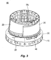
- Figs. 1 and 2 show two perspective views of a tool 100 in accordance with the present invention.
- the tool is in the "molding" state - i.e., the tool 100 is ready to have one or more layers of composite material applied to its axially extending tubular exterior surface to form a tubular composite member, such as an inner skin of an acoustic inner barrel for an aircraft gas turbine engine.
- Fig. 3 shows the tool 100 in the "collapsed" state, in which a tubular composite member formed on the tool may be removed from the tool.
- the tool 100 comprises a base 110 on which is mounted a tubular molding assembly 105.
- the base has a diameter of approximately 3.4 meters while the height of the tool, including the base, is approximately 3.1 meters.
- the base 110 is circular in shape and comprises an upper surface 192 and a skirt 194 extending downwardly therefrom.
- a set of four wheels 196 is attached to the bottom of the base 110 to help roll the base along a floor or other surface on which the base 110 rests.
- the base 110 is also provided with at least one pair of rectangular tubular members 198, each tubular member traversing the base 110 in a chord-like manner.
- the tubular members 198 are configured and dimensioned to serve as forklift receiving structures suitable for receiving forklift prongs, to facilitate lifting and transporting the base 110.
- the tubular molding assembly 105 comprises a fixed segment 200, and three movable segments 210, 220 and 230.
- the term "fixed segment” refers to a segment which, in normal use for molding and curing operations, is fixed relative to the base 110.
- movable segments 210, 220 and 230 are configured as a first door 210, a second door 220 and a third door 230, respectively.
- the fixed segment 200 rests on fixed segment support 202 which comprises a fixed segment support base 348;
- the first door 210 rests on first door support 212 which comprises a first door support base 448;
- the second door 220 rests on second door support 222 which comprises a second door support base 548.
- the first door 210 is hingedly connected at one circumferential end to a first, opposing circumferential end of the fixed segment 200.
- second door 220 is hingedly connected at one circumferential end to a second, opposing circumferential end of the fixed segment 200.
- the third door 230 is hingedly connected to the second door 220, as described further below.
- a door 210, 220, 230 is considered to occupy a 'molding position' when it is closed, such as seen in Figs. 1 and 2 , and is considered to occupy a 'retracted position' whenever it is moved in an inward direction relative to its 'molding position', as seen in Fig. 3 .
- the base 110 is formed from steel while the tubular molding assembly 105 is formed from a different material.
- the tubular molding assembly 105 is formed from a material which has a thermal properties that are similar to that the material to be formed on the tool, over a temperature range to which the assembly is exposed during normal use.
- the tubular molding assembly 105 is formed from INVAR 36® or other material having a coefficient of thermal expansion that is similar to that of a graphite-epoxy composite part that is to be molded on the tool. Having similar thermal coefficients of expansion of the tubular molding assembly 105 and such a part eliminates different thermal expansion rates which otherwise would cause thermal loading between the part and the tool during heating and/or cooling, resulting in damage to the part.
- the thermal coefficients of expansion of the tubular molding assembly 105 and the graphite-epoxy composite part formed thereon differ by less than 10% over the temperature range to which the assembly is exposed during normal use.
- a base formed from steel is less costly than a base formed from a material such as INVAR 36®.
- the fixed segment 200 and each of the doors 210, 220, 230 has an outer surface provided with a predefined contour which conforms to a corresponding portion of the composite tubular structure to be formed using the tool 100.
- the third door 230 fits between facing edges of the first door 210 and the second door 220. And as seen in Figs. 1-2 , the outer surface of the third door 230 forms a portion of an outer contour of the tool, when the tool is in the molding position.
- the third door 230 is constructed and arranged to provide the exterior of the tool 100 with a smooth outer surface in the region between the first door 210 and the second door 220.
- step difference helps promote the aerodynamic properties of the completed part. In one embodiment, this step difference is less than about 0.05 cm. More preferably, however, the step difference is on the order of less than 0.005 cm.
- the third door 230 should be smaller than either the first or second doors 210, 220.
- one function of third door 230 may be to break surface tension of a cured product by initiating separation between the cured product and the outer surface of the tool mandrel on which it is formed.
- the size of the third door may be dictated by the surface area required to break tension, and this may depend on the size of the tool.
- the third door 230 may subtend a smaller circumferential extent in a tool with a larger diameter, than in a tool with a smaller diameter.
- the third door 230 must provide enough clearance to allow the second door 220 to move past the end of the first door 210, in view of the contours of the first and second doors.
- the fixed segment 200 subtends between 160° and 180°, though more preferably is closer to 180°.
- the fixed segment 20 subtends just under 180°
- the first door 210 and second door 220 each subtend approximately, 87°
- the third door 230 subtends approximately 6°.
- the third door 230 has a medial circumferential extent of approximately 15 cm.
- the third door 230 subtends between 3° - 9° out of the full 360° extent of the tool 100.
- the third door 230 has a circumferential extent no greater than one-quarter of a circumferential extent of the smaller of the first door 210 and the second doors 220. More preferably, though, the third door 230 has a circumferential extent no greater than one-tenth of a circumferential extent of the smaller of the first door 210 and the second door.
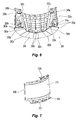
- Figs. 4-6 show the fixed segment 200, its fixed segment support 202, and its fixed segment support base 248 in further detail.
- the fixed segment 200 has a first circumferential end 330a which is opposite a corresponding first circumferential end 430a of the first door 210 (See Fig. 8 ) and a second circumferential end 330a which is opposite a corresponding circumferential end 530a of the second door 220 (see Fig. 11 ), when the tool 100 is in the molding position.
- the circumferential ends 330a, 330a of the fixed segment 200 are each provided with a circumferentially facing panel 338a, 338b, respectively.
- each of these circumferentially facing panels 338a, 338b is provided with a sealing structure 340a, 340b, respectively to help form a seal between the fixed segment 200 and each of the first door 210 and the second door 220.
- each sealing structure is configured as a groove, as discussed further below with respect to Fig. 15 .
- the fixed segment 200 proximate its first circumferential end 330a, is provided with a pair of vertically spaced apart hinge plates 310u, 310n, which connect to opposing vertically spaced apart hinge arms 420u, 420n, respectively, formed on the first circumferential end 430a of the first door 210.
- the fixed segment 200 is provided with a pair of vertically spaced apart hinge plates 320u, 320n, which connect to opposing vertically spaced apart hinge arms 520u, 520n, respectively, formed on the first circumferential end 530b of the second door 220.
- Fig. 6 shows the details of the fixed segment support 202 and the fixed segment support base 348.
- the fixed segment support base 348 has a lower surface to which are affixed a plurality of machined pads 350a-e.
- the machined pads 350a-e are mounted on corresponding mounting pads 150a-e formed on the top surface 192 of the tool base 110 (see Fig. 17A ).
- five such machined pads 350a-e are provided on the fixed segment support base 348 and five corresponding mounting pads 150a-e are provided on the tool base 110.
- Central machined pad 350c is provided with a pair of radially spaced apart clearance holes through which threaded shoulder bolts 360c pass for mating with a pair of radially spaced tapped holes 160c formed on central mounting pad 150c provided on the tool base 110.
- Lateral machine pads 350a, 350e are provided with radially spaced apart pairs of clearance holes through which threaded shoulder bolts 362a, 362e, respectively, pass for mating with radially spaced apart pairs of tapped holes 162a, 162e, respectively, formed on respective lateral mounting pads 150a, 150e.
- First lateral machined pad 350a is further provided with a first fixed pin 363a which mates with a slotted bushing 153a formed on the first lateral mounting pad 150a.
- Second lateral machined pad 350e is provided with a second fixed pin 363b which mates with a round bushing 153e formed on the second lateral mounting pad 150e.
- the slot of the slotted bushing 153a extends in a radial direction to facilitate mounting onto the base 110 and accommodate thermal expansion of the fixed segment 202 relative to the base 110.
- Figs. 7-9 show the first door 210, its first door support 212 and its first door support base 448 in further detail.
- the first door 210 has a first circumferential end 430a which is opposite the corresponding first circumferential end 330a of the fixed segment 200, and a second circumferential end 430c which is opposite a corresponding first circumferential end 630c of the third door 230, when the tool 100 is in the molding position.
- the circumferential ends 430a, 430c of the first door 210 are each provided with a circumferentially facing panel 438a, 438c, respectively.
- circumferentially facing panel 438c is provided with a sealing structure of the sort described above.
- the first door 210 proximate its first circumferential end 430c, the first door 210 is provided with a pair of vertically spaced apart cross-brace receiver pads 410u, 410n which are configured to serve as rigid mounts and mate with free ends of cross-braces 510u, 510n, respectively (see Figs. 10 and 11 ).
- the first door 210 is provided with a pair of vertically spaced apart hinge arms 420u, 420n, which connect to opposing vertically spaced apart hinge plates 310u, 310n, respectively, formed on the fixed segment 200, as described above.
- One or more handles 425 is provided on an interior surface of the first door 210 to facilitate grabbing when the first door 210 is to either be pushed out or pulled inwardly, from inside the tool 100.
- Fig. 9 shows the details of the first door support 212 and the first door support base 448.
- the first door support base 448 has a lower surface to which are affixed a plurality of first door pads 450a-c.
- Each of the first door pads 450a, 450b, 450c is provided with a spherical wheel assembly 470a, 470b, 470c, respectively.
- the wheel assemblies 470a, 470b, 470c roll on first door wear plates 170a, 170b, 170c, respectively, provided on the top surface 192 of the tool base 110 (see Fig. 17A ).
- Fig. 17A shows the details of the first door support 212 and the first door support base 448.
- the first door support base 448 has a lower surface to which are affixed a plurality of first door pads 450a-c.
- Each of the first door pads 450a, 450b, 450c is provided with a spherical wheel assembly 470
- the first door wear plates 170a, 170b, 170c have differing lengths due to the varying degree of travel experienced by the wheel assemblies when the first door 210 is operated.
- the spherical wheel assemblies 470a, 470b, 470c and the wear plates 170a, 170b, 170c allow an operator to manually move the first door 210 along an arcuate path by simply pushing or pulling on one or more door handles. It is understood that the wear plates 170a, 170b, 170c are replaceable.
- the first door pad 450b is additionally provided with a pair of spaced apart first door stops, including a radially outer first door stop 472a and a radially inner first door stop 472b.
- the extent of travel of the first door 210 is limited, at least in part, by these first door stops 472a, 472b, when they abut corresponding first door abutments 172a, 172b provided on the top surface 192 of the tool base 110 (see Fig. 17A ).
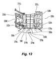
- Figs. 10-12 show the second door 220, its second door support 222 and its second door support base 548 in further detail.
- the second door 220 has a first circumferential end 530b which is opposite the corresponding second circumferential end 330b of the fixed segment 200, and a second circumferential end 530d which is opposite a corresponding second circumferential end 630d of the third door 230, when the tool 100 is in the molding position.
- the circumferential ends 530b, 530d of the second door 220 are each provided with a circumferentially facing panel 538b, 538d, respectively.
- circumferentially facing panel 538d is provided with a sealing structure of the sort described above.
- the second door 220 proximate its first circumferential end 530b, the second door 220 is provided with a pair of vertically spaced apart hinge arms 520u, 520n, which connect to opposing vertically spaced apart hinge plates 320u, 320n, respectively, formed on the fixed segment 200.
- the second door 220 is provided with a pair of vertically spaced apart third door pivot attachments 560u, 560n for connecting to the third door 230, as discussed below.
- the second door 220 is provided with a pair of vertically spaced apart cross-brace pivotal mounts 512u, 512n around which the cross-braces 510u, 510n, respectively, may pivot.
- the opposite free ends of the cross-braces 510u, 510n are connected to the cross-brace receiver pads 410u, 410n provided on the first door 210 to enhance the structural rigidity of the tool 100 and to prevent accidental opening of the tool 100.
- the cross-braces 510u, 510n extend in a lateral direction, parallel to the top surface 192 of the base 110.
- One or more handles 525 is provided on an interior surface of the second door 220 to facilitate grabbing when the second door 220 is to either be pushed out or pulled inwardly, from inside the tool 100.
- Fig. 12 shows the details of the second door support 222 and the second door support base 548.
- the second door support base 548 has a lower surface to which are affixed a plurality of second door pads 550a-c.
- Each of the second door pads 550a, 550b, 550c is provided with a spherical wheel assembly 576a, 576b, 576c, respectively.
- the wheel assemblies 576a, 576b, 576c roll on first door wear plates 176a, 176b, 176c, respectively, provided on the top surface 192 of the tool base 110 (see Fig. 17A ).
- first door wear plates 176a, 176b, 176c respectively
- the second door wear plates 176a, 176b, 176c have differing lengths due to the varying degree of travel experienced by the wheel assemblies when the second door 220 is operated. However, since the second door 220 opens wider than the first door, the lengths of the second door wear plates 176a, 176b, 176c are longer than the corresponding lengths of the first door wear plates 170a, 170b, 170c.
- the spherical wheel assemblies 576a, 576b, 576c and the second door wear plates 176a, 176b, 176c allow an operator to manually move the second door 220 along an arcuate path by simply pushing or pulling on one or more door handles 525. It is understood that the wear plates 176a, 176b, 176c are replaceable.
- first door 210, the second door 220 and the third door 230 can all be manually operated, no external tooling is needed to move the doors between their open and closed positions.
- the second door pad 550b is additionally provided with a pair of spaced apart second door stops, including a radially outer second door stop 574a and a radially inner second door stop 574b.
- the extent of travel of the second door 220 is limited, at least in part, by these second door stops 574a, 574b, when they abut corresponding second door abutments 174a, 174b provided on the top surface 192 of the tool base 110 (see Fig. 17A ).
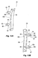
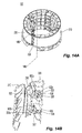
- Figs. 13A and 13B show the third door 230.
- the third door 230 has an exterior surface 632 which conforms to the desired shape of a potion of the part to be made with the tool 100.
- One circumferential end 630d of the third door 230 is provided with a circumferentially facing panel 638d.
- the third door's circumferentially facing panel 638d opposes the second door's circumferentially facing panel 538d.
- the other circumferential end 630c of the third door 230 is provided with a circumferentially facing edge 648c which is narrower than a width of the circumferentially facing panel 638d.
- the third door's circumferentially facing edge 648c opposes the first door's circumferentially facing panel 438c.
- the third door is provided with a pair of vertically spaced apart "goose-neck" or U-shaped hinges 620u, 620n.
- the U-shaped hinges 620u, 620n are rigidly mounted to the third door 230 on an inner surface thereof.
- the free ends 624 of the U-shaped hinges 620u, 620n are provided with pivot openings 626 for mounting on the aforementioned vertically spaced apart third door pivot attachments 560u, 560n, each of which is located on a hinge plate 528 of the second door 220 (see Fig. 14B ).
- each U-shaped hinge 620u, 620n is provided with a hinge block 622 and a hinge pin receiving bore 628.
- Each hinge pinning block 622 cooperates with a corresponding second door block 522 mounted proximate the circumferential second end 530d of the second door 220, as discussed below with respect to Fig. 14B .
- Each hinge pin receiving bore 628 is configured to receive a hinge pin 636.
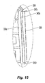
- Fig. 14A shows the tool 100 with the first door 210 and the second door 220 still in the molding position, but with the third door 230 ajar.
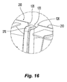
- Fig. 14B shows an enlarged view from the interior of the tool 100 as seen in Fig. 14A , the view taken along cross-sectional line 14B - 14B.
- the third door 230 opens towards the interior of the tool 100 with each U-shaped hinge 620u, 620n passing just above a corresponding hinge plate 528.
- Each hinge plate 528 carries a second door block 522, a corresponding third door pivot attachment 560u or 560n, and a hinge plate bore (not shown).
- the hinge pin receiving bore 628 is aligned with a hinge plate bore formed in the hinge plate 528, and the hinge pin 636 may be inserted into the aligned bores to prevent the hinge 620u, 620n from pivoting, i.e., prevent the third door 230 from accidentally opening.
- each hinge block 622 is brought into juxtaposition with a corresponding second door block 522, and openings 622a, 522a formed in the respective blocks 622, 522 become aligned.
- a bolt may be inserted into the aligned openings 622a, 522a to further secure the third door 230 in the closed position.
- an interface panel such as interface panel 338a is provided with a sealing structure in form of a circumferentially facing groove 340a
- the groove 340a extends substantially along the entire height of the interface panel 338a and has radially outwardly extending upper and lower groove channels 342u, 342n.
- the groove 340A is configured and dimensioned to snugly receive an appropriately sized and shaped flexible sealing member 390.
- the flexible sealing member comprises a tubular section of flexible material, such as rubber.
- the sealing structure 340a and the flexible sealing member 390 together form a sealing arrangement. When the tool is in the molding portion, this sealing arrangement helps form a seal between adjacent segments.
- the interface between the fixed segment 200 and the first door 210 has such a sealing arrangement, as does the interface between the fixed segment 200 and the second door 210.
- a similar sealing arrangement is also provided at the interface between the first door 210 and the third door 230, and at the interface between the second door 220 and the third door 230.
- the grooves are formed on both circumferentially facing panels 338a, 338b of the fixed segment 200, on the first door's circumferentially facing panel 438c that faces the third door 230, and on the second door's circumferentially facing panel 538d that faces the third door 230.
- notches 120 are formed between the fixed segment 200 and the first door 210, and also between the fixed segment 200 and the second door 220.
- Each notch 120 is created when cutouts 126 formed at the top and bottom corners of the fixed segment 200 and at the corresponding facing corners of the doors 210, 220 are brought together when the doors are closed.
- the notches 120 facilitate the use of vacuum bagging in the event the compressible seals fail. More particularly, the notches are regions where ends of polymer films for vacuum bagging meet to seal the composite material, prior to and during curing, in a manner known to those skilled in the art.
- a cover member 370 is provided to protect plastic bags during vacuum sealing from sharp edges at the interface between the fixed segment 200 and the first door 210
- one fixed segment and three movable segments in the form of three doors were employed, the smallest door being substantially smaller than either of the other two doors.
- the larger of the two doors is hingedly connected at a first circumferential end to a first circumferential end of the fixed segment.
- a first circumferential end of the smaller of the two doors is then hingedly connected to the larger door's second circumferential end.
- the second circumferential end of the smaller of the two doors meets the second circumferential end of the fixed segment to thereby form the 360° tool.
- Sealing arrangements including grooves and sealing members as described above may be provided at the three interfaces.
- the fixed portion may again subtend roughly 180°
- the first (larger) hinged door may subtend about 144° - 164°
- the second (smaller) hinged door hindered to the may subtend the remainder of about 16° - 36° (or roughly one-quarter to one-tenth the size of the larger door).
- the non-right-cylindrical geometry of the tool may determine whether or not such a three-segment section is at all possible, and may also help determine the size for the smaller door.
- the tool 100 is adjusted to the molding position and composite material is applied in a pre-determined horizontal band between the upper and lower edges of the fixed segment 200 and the doors 210, 220, 230. After the composite material has been applied, it is covered with plastic film and vacuum sealed. The plastic film is placed on the outside of the tool over the composite material, and also on the inside of the tool over the interface regions between the various segments 200, 210, 220, 230.
- An upper bead of sealant and a lower bead of sealant may be circumferentially applied around the outer surface of the tool 100 to adhere the plastic film to the tool 100.
- vacuum bag sealant tape two-sided "chromate tape” with peel-off backing on both sides
- model no. GS 213-3 available from General Sealants of Industry, CA may be suitable for use as sealant beads.
- a first portion of polymer film such as a nylon film
- This first portion of film is a single piece that extends around the entire circumference of the tool and is overlapped in the circumferential direction by 2-3 centimeters or so, the overlapping ends secured by an axially extending piece of chromate tape.
- This first portion of nylon film is of sufficient height to contact the upper and lower beads.
- the upper edge of the nylon film extends above the upper bead around the entire circumference of the tool, while the lower edge of the first portion of nylon film extends below the lower bead around the entire circumference of the tool.
- the first portion of the film also extends across each notch 120, and is secured to those portions of the beads that extend across each notch.
- an IPPLON® KM 1300 nylon film available from Airtech International, Inc. of Huntington Beach, CA may be used.
- Second portions of nylon film which are sized to cover each of the interface regions between the segments may optionally be applied on the inside surface of the tool 100 and are secured to the first portion of nylon film via beads at the notches, in a known manner.
- the first film portion and the second film portion may sealingly join and engage each other. This serves as a backup in case the sealing members 390 fail.
- a vacuum bag is formed, the vacuum bag creating a seal around the interface regions and the adjoining areas where the edges of the segments 200, 210, 220, 230 are present.
- FIG. 18 An exemplary use of the tool 100 is presented next with reference to Fig. 18 .
- This exemplary use illustrates one embodiment of a process 800 for making a composite inner skin of a 360° acoustic inner barrel for a nacelle inlet, using the tool 100.
- the process entails a number of phases: tool surface preparation 802; tool assembly 804; application of composite material 806; preparation for curing 808; curing in an autoclave 810; and composite inner skin removal 812.
- tool surface preparation 802 tool assembly 804
- application of composite material 806 preparation for curing 808
- curing in an autoclave 810 curing in an autoclave 810
- People skilled in the art are familiar with these processes, as evidenced by aforementioned U.S. Published Application No. 2007/0062022 .
- the tool surface preparation process 802 entails:
- the tool assembly process 804 entails:
- composite material is applied to the external surface of the tool in a conventional lay-up process and compacted by vacuum.
- the composite material application and compaction process 806 entails:
- the autoclave curing phase 810 entails:
- the composite inner skin removal process 812 entails:
- the composite inner skin is formed, it generally is subject to additional processing, such as perforation for acoustic attenuation. This, however, is done by a separate process using separate tools.
- the acoustic core and the outer skin are also formed using separate processes and separate tools.
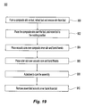
- a bond panel for an acoustic inner barrel may be formed by bonding together the composite inner skin, the acoustic core and the outer skin, with help of the tool 100.
- Fig. 19 shows a process 900 to accomplish this.
- the composite inner skin is placed over a slightly collapsed tool 100 and the tool is then adjusted to the molding position such that the outer surface of the tool supports the inner skin.
- the composite inner skin may first have been molded on the tool, the doors 210, 220, 230 opened and the composite inner skin removed from the tool 100, and only then subsequently repositioned on the tool 100.
- step 904 the acoustic core (e.g., honeycomb core typically used in engine nacelles) is positioned over the composite inner skin and bonded thereto.
- step 906 the outer skin is positioned over the acoustic core and bonded thereto.
- step 908 the resulting assembly is then cured in an autoclave.
- step 910 the bonded inner skin/core/outer skin assembly is removed from the tool. People skilled in the art understand how to bond adjacent layers for such an acoustic liner.
Landscapes
- Engineering & Computer Science (AREA)
- Mechanical Engineering (AREA)
- Chemical & Material Sciences (AREA)
- Composite Materials (AREA)
- Moulding By Coating Moulds (AREA)
Priority Applications (1)
| Application Number | Priority Date | Filing Date | Title |
|---|---|---|---|
| EP12000610.1A EP2450171B1 (de) | 2008-03-21 | 2009-03-11 | Vorrichtung und Verfahren zum Herstellen einer rohrförmigen Verbundtrommel |
Applications Claiming Priority (1)
| Application Number | Priority Date | Filing Date | Title |
|---|---|---|---|
| US12/052,968 US7640961B2 (en) | 2008-03-21 | 2008-03-21 | Apparatus and method for making a tubular composite barrel |
Related Child Applications (1)
| Application Number | Title | Priority Date | Filing Date |
|---|---|---|---|
| EP12000610.1 Division-Into | 2012-01-31 |
Publications (3)
| Publication Number | Publication Date |
|---|---|
| EP2103404A2 true EP2103404A2 (de) | 2009-09-23 |
| EP2103404A3 EP2103404A3 (de) | 2011-03-02 |
| EP2103404B1 EP2103404B1 (de) | 2012-06-06 |
Family
ID=40848219
Family Applications (2)
| Application Number | Title | Priority Date | Filing Date |
|---|---|---|---|
| EP09003566A Not-in-force EP2103404B1 (de) | 2008-03-21 | 2009-03-11 | Vorrichtung und Verfahren zum Herstellen einer rohrförmigen Verbundtrommel |
| EP12000610.1A Not-in-force EP2450171B1 (de) | 2008-03-21 | 2009-03-11 | Vorrichtung und Verfahren zum Herstellen einer rohrförmigen Verbundtrommel |
Family Applications After (1)
| Application Number | Title | Priority Date | Filing Date |
|---|---|---|---|
| EP12000610.1A Not-in-force EP2450171B1 (de) | 2008-03-21 | 2009-03-11 | Vorrichtung und Verfahren zum Herstellen einer rohrförmigen Verbundtrommel |
Country Status (2)
| Country | Link |
|---|---|
| US (2) | US7640961B2 (de) |
| EP (2) | EP2103404B1 (de) |
Cited By (6)
| Publication number | Priority date | Publication date | Assignee | Title |
|---|---|---|---|---|
| RU2482028C1 (ru) * | 2011-12-21 | 2013-05-20 | Открытое акционерное общество "Национальный институт авиационных технологий" (ОАО НИАТ) | Стапель для сборки воздухозаборника двигателя летательного аппарата |
| RU183441U1 (ru) * | 2017-12-29 | 2018-09-24 | Акционерное общество "НПО Энергомаш имени академика В.П. Глушко" | Стапель для сборки трехмерной конструкции рамы жидкостного ракетного двигателя |
| GB2571173A (en) * | 2017-12-18 | 2019-08-21 | Boeing Co | Layup tools that facilitate transfer of laminates to cure tools |
| GB2575295A (en) * | 2018-07-04 | 2020-01-08 | Rolls Royce Plc | An Alignment Tool |
| CN112045906A (zh) * | 2020-08-27 | 2020-12-08 | 冀州中意复合材料股份有限公司 | 一种大型开合复合烟道模具 |
| US11407185B2 (en) | 2017-12-18 | 2022-08-09 | The Boeing Company | Layup tools that facilitate transfer of laminates to cure tools |
Families Citing this family (12)
| Publication number | Priority date | Publication date | Assignee | Title |
|---|---|---|---|---|
| US7707708B2 (en) * | 2005-09-21 | 2010-05-04 | Rohr, Inc. | Apparatus for making a tubular composite structure |
| GB2449907B (en) * | 2007-06-07 | 2010-02-10 | Gkn Aerospace Services Ltd | Composite flange and method of making such flange |
| US8025499B2 (en) * | 2008-11-03 | 2011-09-27 | Rohr, Inc. | Multi-segment tool and method for composite formation |
| US8661644B2 (en) | 2010-10-06 | 2014-03-04 | The Boeing Company | Method and device for forming joints in composite structures |
| US8784596B2 (en) | 2010-11-19 | 2014-07-22 | The Boeing Company | Method for making and joining composite sandwich shell edge joint |
| US8875931B2 (en) | 2010-11-19 | 2014-11-04 | The Boeing Company | Composite sandwich shell edge joint |
| FR2991628A1 (fr) * | 2012-06-12 | 2013-12-13 | Aircelle Sa | Ensemble d'outillage pour la fabrication d'une piece composite et procede de fabrication d'une piece composite. |
| DE202013103475U1 (de) * | 2013-08-02 | 2014-11-04 | Krones Aktiengesellschaft | Vakuumzylinder für eine Etikettiervorrichtung und Etikettiervorrichtung mit einem Vakuumzylinder |
| US10094242B2 (en) * | 2014-02-25 | 2018-10-09 | United Technologies Corporation | Repair or remanufacture of liner panels for a gas turbine engine |
| US10137607B2 (en) | 2014-10-01 | 2018-11-27 | The Boeing Company | Methods and apparatus for curing composite nacelle structure |
| FR3084445B1 (fr) * | 2018-07-25 | 2021-01-22 | Safran Aircraft Engines | Fabrication d'une chambre de combustion en materiau composite |
| IT201900004761A1 (it) | 2019-03-29 | 2020-09-29 | Leonardo Spa | Procedimento di fabbricazione di un pannello fonoassorbente con struttura a sandwich per la riduzione dell’impatto sonoro di un motore aeronautico |
Citations (2)
| Publication number | Priority date | Publication date | Assignee | Title |
|---|---|---|---|---|
| US7125237B2 (en) | 2002-06-27 | 2006-10-24 | Airbus France | Tooling for molding with keys particularly for the production of air intakes without clips |
| US20070062022A1 (en) | 2005-09-21 | 2007-03-22 | Rohr, Inc. | Method and apparatus for making a tubular composite structure |
Family Cites Families (27)
| Publication number | Priority date | Publication date | Assignee | Title |
|---|---|---|---|---|
| US1835986A (en) | 1927-10-12 | 1931-12-08 | Nat Rubber Machinery Co | Collapsible tire building form |
| US2586300A (en) * | 1947-08-07 | 1952-02-19 | John F Campbell | Collapsible v-belt mold |
| DE1262570B (de) | 1964-06-18 | 1968-03-07 | Mueller Ernst Kg | Hohldorn zum Herstellen von aus schraubenlinienfoermig gewickelten Kunststoffstreifen bestehenden Rohren oder Behaeltermaenteln beliebiger Laenge |
| DE1504597B2 (de) | 1965-11-06 | 1971-04-01 | Muller geb Schneider, Hedwig Ida, 5905 Freudenberg | Hohldorn zum herstellen von aus schrabenlinienfoermig ge wickelten kunststoffstreifen bestehenden rohren oder behaeltermaentel beliebiger laenge |
| US3768954A (en) * | 1969-06-03 | 1973-10-30 | R Marsh | Device for forming and handling concrete pipe |
| DE2259690A1 (de) | 1972-12-06 | 1974-06-12 | Bautenberg Gmbh | Hohler wickeldorn |
| DE2352373A1 (de) | 1973-10-18 | 1975-04-24 | Hermann Sarres | Wickeldorn zur herstellung von zylindrischen koerpern aus wickel- oder spritzfaehigen kunststoffen |
| GB1522558A (en) | 1976-04-05 | 1978-08-23 | Rolls Royce | Duct linings |
| DE2652862C2 (de) | 1976-11-20 | 1979-01-04 | Basf Ag, 6700 Ludwigshafen | Formkern zum Herstellen von aus faserverstärktem Kunstharz bestehenden Hohlkörpern |
| US4288277A (en) | 1979-07-17 | 1981-09-08 | Lembit Siilats | Molding system with retracting mold |
| US4278490A (en) | 1979-12-21 | 1981-07-14 | Owens-Corning Fiberglas Corporation | Sleeve for changing diameter of collapsible mandrel |
| US4436574A (en) | 1982-12-13 | 1984-03-13 | Eagle-Picher Industries, Inc. | Radial mandrel |
| US4462787A (en) * | 1983-02-01 | 1984-07-31 | Bogardus Jr Carl R | Cantilevered mandrel assembly |
| EP0154038B1 (de) | 1984-02-08 | 1989-03-15 | Georg Prinzing GmbH & Co. KG Betonformen- und Maschinenfabrik | Formkern mit verstellbaren Teilen |
| IT1177395B (it) | 1984-12-12 | 1987-08-26 | Dino Piccoli | Apparecchiatura per la produzione in discontinuo di strutture tubolari |
| ATE47087T1 (de) * | 1986-08-23 | 1989-10-15 | Vv System Ag | Spreizbarer ring zum abdichten einer huelle am wulst eines rundzuerneuernden reifens. |
| US5022845A (en) * | 1989-04-25 | 1991-06-11 | Hercules Incorporated | Segmented mandrel for forming composite articles |
| WO1992014672A1 (en) | 1991-02-19 | 1992-09-03 | Boyd John W | Method and apparatus for producing a filament wound tank shell |
| US5228374A (en) * | 1991-08-09 | 1993-07-20 | Santeramo Sr Joseph J | Table saw fence assembly |
| US5266137A (en) | 1992-11-10 | 1993-11-30 | Hollingsworth Ritch D | Rigid segmented mandrel with inflatable support |
| DE4340951A1 (de) | 1992-12-04 | 1994-06-09 | Grumman Aerospace Corp | Einstückiges Triebwerkeinlaß-Schallrohr |
| FR2767560B1 (fr) | 1997-08-19 | 1999-11-12 | Aerospatiale | Ensemble reducteur de bruit pour turboreacteur d'aeronef |
| US6458309B1 (en) | 1998-06-01 | 2002-10-01 | Rohr, Inc. | Method for fabricating an advanced composite aerostructure article having an integral co-cured fly away hollow mandrel |
| DE10010917A1 (de) * | 2000-03-06 | 2001-09-13 | Baumgaertner Maschf Gmbh | Formmantel |
| FR2821788B1 (fr) | 2001-03-09 | 2004-04-02 | Eads Airbus Sa | Procede de fabrication d'un panneau a couche resistive acoustique adaptee et panneau acoustique ainsi obtenu |
| CN1972792B (zh) * | 2004-06-21 | 2011-04-06 | 有限会社尽田产业 | 模具、注射成形装置以及注射成形方法 |
| US7571527B2 (en) | 2005-03-29 | 2009-08-11 | The Boeing Company | Mandrel for fabrication of a monolithic composite nacelle panel |
-
2008
- 2008-03-21 US US12/052,968 patent/US7640961B2/en not_active Expired - Fee Related
-
2009
- 2009-03-11 EP EP09003566A patent/EP2103404B1/de not_active Not-in-force
- 2009-03-11 EP EP12000610.1A patent/EP2450171B1/de not_active Not-in-force
- 2009-11-19 US US12/622,138 patent/US8012286B2/en not_active Expired - Fee Related
Patent Citations (2)
| Publication number | Priority date | Publication date | Assignee | Title |
|---|---|---|---|---|
| US7125237B2 (en) | 2002-06-27 | 2006-10-24 | Airbus France | Tooling for molding with keys particularly for the production of air intakes without clips |
| US20070062022A1 (en) | 2005-09-21 | 2007-03-22 | Rohr, Inc. | Method and apparatus for making a tubular composite structure |
Cited By (10)
| Publication number | Priority date | Publication date | Assignee | Title |
|---|---|---|---|---|
| RU2482028C1 (ru) * | 2011-12-21 | 2013-05-20 | Открытое акционерное общество "Национальный институт авиационных технологий" (ОАО НИАТ) | Стапель для сборки воздухозаборника двигателя летательного аппарата |
| GB2571173A (en) * | 2017-12-18 | 2019-08-21 | Boeing Co | Layup tools that facilitate transfer of laminates to cure tools |
| US11407185B2 (en) | 2017-12-18 | 2022-08-09 | The Boeing Company | Layup tools that facilitate transfer of laminates to cure tools |
| GB2571173B (en) * | 2017-12-18 | 2022-09-07 | Boeing Co | Layup tools that facilitate transfer of laminates to cure tools |
| RU183441U1 (ru) * | 2017-12-29 | 2018-09-24 | Акционерное общество "НПО Энергомаш имени академика В.П. Глушко" | Стапель для сборки трехмерной конструкции рамы жидкостного ракетного двигателя |
| GB2575295A (en) * | 2018-07-04 | 2020-01-08 | Rolls Royce Plc | An Alignment Tool |
| US11346254B2 (en) | 2018-07-04 | 2022-05-31 | Rolls-Royce Plc | Alignment tool |
| GB2575295B (en) * | 2018-07-04 | 2022-06-15 | Rolls Royce Plc | An Alignment Tool |
| CN112045906A (zh) * | 2020-08-27 | 2020-12-08 | 冀州中意复合材料股份有限公司 | 一种大型开合复合烟道模具 |
| CN112045906B (zh) * | 2020-08-27 | 2022-03-25 | 冀州中意复合材料股份有限公司 | 一种大型开合复合烟道模具 |
Also Published As
| Publication number | Publication date |
|---|---|
| EP2103404B1 (de) | 2012-06-06 |
| US20100059185A1 (en) | 2010-03-11 |
| US20090236779A1 (en) | 2009-09-24 |
| US7640961B2 (en) | 2010-01-05 |
| EP2103404A3 (de) | 2011-03-02 |
| US8012286B2 (en) | 2011-09-06 |
| EP2450171A1 (de) | 2012-05-09 |
| EP2450171B1 (de) | 2013-05-08 |
Similar Documents
| Publication | Publication Date | Title |
|---|---|---|
| EP2103404B1 (de) | Vorrichtung und Verfahren zum Herstellen einer rohrförmigen Verbundtrommel | |
| US7861394B2 (en) | Method for making a tubular composite structure | |
| US7935289B2 (en) | Method of making composite panels for a fuselage | |
| JP5882361B2 (ja) | 起伏のある複合構造物を製造するための方法 | |
| US8303758B2 (en) | Methods for manufacturing composite sections for aircraft fuselages and other structures | |
| US9962917B2 (en) | Method of manufacturing single piece fuselage barrels in composite material | |
| JP5628214B2 (ja) | 輪郭成形複合構造物を製造する方法 | |
| EP0904929B1 (de) | Verfahren zum Formen eines inneren Druckstücks während des Formen eines Produktes | |
| US11565460B2 (en) | Systems and methods for in situ manufacturing of minimally tooled stringers | |
| CA2753735C (en) | Method and apparatus for manufacturing composite parts | |
| EP4011606B1 (de) | Pressblechsystem für die herstellung von flugzeugen | |
| EP4074497B1 (de) | Druckplatte mit integrierten randabdichtungen und abdichtungsverfahren |
Legal Events
| Date | Code | Title | Description |
|---|---|---|---|
| PUAI | Public reference made under article 153(3) epc to a published international application that has entered the european phase |
Free format text: ORIGINAL CODE: 0009012 |
|
| 17P | Request for examination filed |
Effective date: 20090311 |
|
| AK | Designated contracting states |
Kind code of ref document: A2 Designated state(s): AT BE BG CH CY CZ DE DK EE ES FI FR GB GR HR HU IE IS IT LI LT LU LV MC MK MT NL NO PL PT RO SE SI SK TR |
|
| AX | Request for extension of the european patent |
Extension state: AL BA RS |
|
| PUAL | Search report despatched |
Free format text: ORIGINAL CODE: 0009013 |
|
| AK | Designated contracting states |
Kind code of ref document: A3 Designated state(s): AT BE BG CH CY CZ DE DK EE ES FI FR GB GR HR HU IE IS IT LI LT LU LV MC MK MT NL NO PL PT RO SE SI SK TR |
|
| AX | Request for extension of the european patent |
Extension state: AL BA RS |
|
| GRAP | Despatch of communication of intention to grant a patent |
Free format text: ORIGINAL CODE: EPIDOSNIGR1 |
|
| AKX | Designation fees paid |
Designated state(s): AT BE BG CH CY CZ DE DK EE ES FI FR GB GR HR HU IE IS IT LI LT LU LV MC MK MT NL NO PL PT RO SE SI SK TR |
|
| GRAS | Grant fee paid |
Free format text: ORIGINAL CODE: EPIDOSNIGR3 |
|
| GRAA | (expected) grant |
Free format text: ORIGINAL CODE: 0009210 |
|
| AK | Designated contracting states |
Kind code of ref document: B1 Designated state(s): AT BE BG CH CY CZ DE DK EE ES FI FR GB GR HR HU IE IS IT LI LT LU LV MC MK MT NL NO PL PT RO SE SI SK TR |
|
| REG | Reference to a national code |
Ref country code: GB Ref legal event code: FG4D |
|
| REG | Reference to a national code |
Ref country code: AT Ref legal event code: REF Ref document number: 560791 Country of ref document: AT Kind code of ref document: T Effective date: 20120615 Ref country code: CH Ref legal event code: EP |
|
| REG | Reference to a national code |
Ref country code: IE Ref legal event code: FG4D |
|
| REG | Reference to a national code |
Ref country code: DE Ref legal event code: R096 Ref document number: 602009007398 Country of ref document: DE Effective date: 20120802 |
|
| REG | Reference to a national code |
Ref country code: NL Ref legal event code: VDEP Effective date: 20120606 |
|
| PG25 | Lapsed in a contracting state [announced via postgrant information from national office to epo] |
Ref country code: NO Free format text: LAPSE BECAUSE OF FAILURE TO SUBMIT A TRANSLATION OF THE DESCRIPTION OR TO PAY THE FEE WITHIN THE PRESCRIBED TIME-LIMIT Effective date: 20120906 Ref country code: FI Free format text: LAPSE BECAUSE OF FAILURE TO SUBMIT A TRANSLATION OF THE DESCRIPTION OR TO PAY THE FEE WITHIN THE PRESCRIBED TIME-LIMIT Effective date: 20120606 Ref country code: SE Free format text: LAPSE BECAUSE OF FAILURE TO SUBMIT A TRANSLATION OF THE DESCRIPTION OR TO PAY THE FEE WITHIN THE PRESCRIBED TIME-LIMIT Effective date: 20120606 Ref country code: CY Free format text: LAPSE BECAUSE OF FAILURE TO SUBMIT A TRANSLATION OF THE DESCRIPTION OR TO PAY THE FEE WITHIN THE PRESCRIBED TIME-LIMIT Effective date: 20120606 Ref country code: LT Free format text: LAPSE BECAUSE OF FAILURE TO SUBMIT A TRANSLATION OF THE DESCRIPTION OR TO PAY THE FEE WITHIN THE PRESCRIBED TIME-LIMIT Effective date: 20120606 |
|
| REG | Reference to a national code |
Ref country code: AT Ref legal event code: MK05 Ref document number: 560791 Country of ref document: AT Kind code of ref document: T Effective date: 20120606 |
|
| REG | Reference to a national code |
Ref country code: LT Ref legal event code: MG4D Effective date: 20120606 |
|
| PG25 | Lapsed in a contracting state [announced via postgrant information from national office to epo] |
Ref country code: LV Free format text: LAPSE BECAUSE OF FAILURE TO SUBMIT A TRANSLATION OF THE DESCRIPTION OR TO PAY THE FEE WITHIN THE PRESCRIBED TIME-LIMIT Effective date: 20120606 Ref country code: HR Free format text: LAPSE BECAUSE OF FAILURE TO SUBMIT A TRANSLATION OF THE DESCRIPTION OR TO PAY THE FEE WITHIN THE PRESCRIBED TIME-LIMIT Effective date: 20120606 Ref country code: SI Free format text: LAPSE BECAUSE OF FAILURE TO SUBMIT A TRANSLATION OF THE DESCRIPTION OR TO PAY THE FEE WITHIN THE PRESCRIBED TIME-LIMIT Effective date: 20120606 Ref country code: GR Free format text: LAPSE BECAUSE OF FAILURE TO SUBMIT A TRANSLATION OF THE DESCRIPTION OR TO PAY THE FEE WITHIN THE PRESCRIBED TIME-LIMIT Effective date: 20120907 |
|
| PG25 | Lapsed in a contracting state [announced via postgrant information from national office to epo] |
Ref country code: CZ Free format text: LAPSE BECAUSE OF FAILURE TO SUBMIT A TRANSLATION OF THE DESCRIPTION OR TO PAY THE FEE WITHIN THE PRESCRIBED TIME-LIMIT Effective date: 20120606 Ref country code: EE Free format text: LAPSE BECAUSE OF FAILURE TO SUBMIT A TRANSLATION OF THE DESCRIPTION OR TO PAY THE FEE WITHIN THE PRESCRIBED TIME-LIMIT Effective date: 20120606 Ref country code: NL Free format text: LAPSE BECAUSE OF FAILURE TO SUBMIT A TRANSLATION OF THE DESCRIPTION OR TO PAY THE FEE WITHIN THE PRESCRIBED TIME-LIMIT Effective date: 20120606 Ref country code: IS Free format text: LAPSE BECAUSE OF FAILURE TO SUBMIT A TRANSLATION OF THE DESCRIPTION OR TO PAY THE FEE WITHIN THE PRESCRIBED TIME-LIMIT Effective date: 20121006 Ref country code: SK Free format text: LAPSE BECAUSE OF FAILURE TO SUBMIT A TRANSLATION OF THE DESCRIPTION OR TO PAY THE FEE WITHIN THE PRESCRIBED TIME-LIMIT Effective date: 20120606 Ref country code: BE Free format text: LAPSE BECAUSE OF FAILURE TO SUBMIT A TRANSLATION OF THE DESCRIPTION OR TO PAY THE FEE WITHIN THE PRESCRIBED TIME-LIMIT Effective date: 20120606 Ref country code: RO Free format text: LAPSE BECAUSE OF FAILURE TO SUBMIT A TRANSLATION OF THE DESCRIPTION OR TO PAY THE FEE WITHIN THE PRESCRIBED TIME-LIMIT Effective date: 20120606 Ref country code: AT Free format text: LAPSE BECAUSE OF FAILURE TO SUBMIT A TRANSLATION OF THE DESCRIPTION OR TO PAY THE FEE WITHIN THE PRESCRIBED TIME-LIMIT Effective date: 20120606 |
|
| PG25 | Lapsed in a contracting state [announced via postgrant information from national office to epo] |
Ref country code: IT Free format text: LAPSE BECAUSE OF FAILURE TO SUBMIT A TRANSLATION OF THE DESCRIPTION OR TO PAY THE FEE WITHIN THE PRESCRIBED TIME-LIMIT Effective date: 20120606 Ref country code: PT Free format text: LAPSE BECAUSE OF FAILURE TO SUBMIT A TRANSLATION OF THE DESCRIPTION OR TO PAY THE FEE WITHIN THE PRESCRIBED TIME-LIMIT Effective date: 20121008 Ref country code: PL Free format text: LAPSE BECAUSE OF FAILURE TO SUBMIT A TRANSLATION OF THE DESCRIPTION OR TO PAY THE FEE WITHIN THE PRESCRIBED TIME-LIMIT Effective date: 20120606 |
|
| PLBE | No opposition filed within time limit |
Free format text: ORIGINAL CODE: 0009261 |
|
| STAA | Information on the status of an ep patent application or granted ep patent |
Free format text: STATUS: NO OPPOSITION FILED WITHIN TIME LIMIT |
|
| PG25 | Lapsed in a contracting state [announced via postgrant information from national office to epo] |
Ref country code: DK Free format text: LAPSE BECAUSE OF FAILURE TO SUBMIT A TRANSLATION OF THE DESCRIPTION OR TO PAY THE FEE WITHIN THE PRESCRIBED TIME-LIMIT Effective date: 20120606 |
|
| 26N | No opposition filed |
Effective date: 20130307 |
|
| REG | Reference to a national code |
Ref country code: DE Ref legal event code: R097 Ref document number: 602009007398 Country of ref document: DE Effective date: 20130307 |
|
| PG25 | Lapsed in a contracting state [announced via postgrant information from national office to epo] |
Ref country code: BG Free format text: LAPSE BECAUSE OF FAILURE TO SUBMIT A TRANSLATION OF THE DESCRIPTION OR TO PAY THE FEE WITHIN THE PRESCRIBED TIME-LIMIT Effective date: 20120906 |
|
| PG25 | Lapsed in a contracting state [announced via postgrant information from national office to epo] |
Ref country code: MC Free format text: LAPSE BECAUSE OF NON-PAYMENT OF DUE FEES Effective date: 20130331 Ref country code: ES Free format text: LAPSE BECAUSE OF FAILURE TO SUBMIT A TRANSLATION OF THE DESCRIPTION OR TO PAY THE FEE WITHIN THE PRESCRIBED TIME-LIMIT Effective date: 20120917 |
|
| REG | Reference to a national code |
Ref country code: CH Ref legal event code: PL |
|
| REG | Reference to a national code |
Ref country code: IE Ref legal event code: MM4A |
|
| PG25 | Lapsed in a contracting state [announced via postgrant information from national office to epo] |
Ref country code: IE Free format text: LAPSE BECAUSE OF NON-PAYMENT OF DUE FEES Effective date: 20130311 Ref country code: CH Free format text: LAPSE BECAUSE OF NON-PAYMENT OF DUE FEES Effective date: 20130331 Ref country code: LI Free format text: LAPSE BECAUSE OF NON-PAYMENT OF DUE FEES Effective date: 20130331 |
|
| PG25 | Lapsed in a contracting state [announced via postgrant information from national office to epo] |
Ref country code: MT Free format text: LAPSE BECAUSE OF FAILURE TO SUBMIT A TRANSLATION OF THE DESCRIPTION OR TO PAY THE FEE WITHIN THE PRESCRIBED TIME-LIMIT Effective date: 20120606 |
|
| PG25 | Lapsed in a contracting state [announced via postgrant information from national office to epo] |
Ref country code: TR Free format text: LAPSE BECAUSE OF FAILURE TO SUBMIT A TRANSLATION OF THE DESCRIPTION OR TO PAY THE FEE WITHIN THE PRESCRIBED TIME-LIMIT Effective date: 20120606 |
|
| PG25 | Lapsed in a contracting state [announced via postgrant information from national office to epo] |
Ref country code: LU Free format text: LAPSE BECAUSE OF NON-PAYMENT OF DUE FEES Effective date: 20130311 Ref country code: HU Free format text: LAPSE BECAUSE OF FAILURE TO SUBMIT A TRANSLATION OF THE DESCRIPTION OR TO PAY THE FEE WITHIN THE PRESCRIBED TIME-LIMIT; INVALID AB INITIO Effective date: 20090311 Ref country code: MK Free format text: LAPSE BECAUSE OF FAILURE TO SUBMIT A TRANSLATION OF THE DESCRIPTION OR TO PAY THE FEE WITHIN THE PRESCRIBED TIME-LIMIT Effective date: 20120606 |
|
| REG | Reference to a national code |
Ref country code: FR Ref legal event code: PLFP Year of fee payment: 8 |
|
| REG | Reference to a national code |
Ref country code: FR Ref legal event code: PLFP Year of fee payment: 9 |
|
| REG | Reference to a national code |
Ref country code: FR Ref legal event code: PLFP Year of fee payment: 10 |
|
| PGFP | Annual fee paid to national office [announced via postgrant information from national office to epo] |
Ref country code: DE Payment date: 20200218 Year of fee payment: 12 Ref country code: GB Payment date: 20200221 Year of fee payment: 12 |
|
| PGFP | Annual fee paid to national office [announced via postgrant information from national office to epo] |
Ref country code: FR Payment date: 20200220 Year of fee payment: 12 |
|
| REG | Reference to a national code |
Ref country code: DE Ref legal event code: R119 Ref document number: 602009007398 Country of ref document: DE |
|
| GBPC | Gb: european patent ceased through non-payment of renewal fee |
Effective date: 20210311 |
|
| PG25 | Lapsed in a contracting state [announced via postgrant information from national office to epo] |
Ref country code: DE Free format text: LAPSE BECAUSE OF NON-PAYMENT OF DUE FEES Effective date: 20211001 Ref country code: GB Free format text: LAPSE BECAUSE OF NON-PAYMENT OF DUE FEES Effective date: 20210311 Ref country code: FR Free format text: LAPSE BECAUSE OF NON-PAYMENT OF DUE FEES Effective date: 20210331 |