US5022845A - Segmented mandrel for forming composite articles - Google Patents
Segmented mandrel for forming composite articles Download PDFInfo
- Publication number
- US5022845A US5022845A US07/343,453 US34345389A US5022845A US 5022845 A US5022845 A US 5022845A US 34345389 A US34345389 A US 34345389A US 5022845 A US5022845 A US 5022845A
- Authority
- US
- United States
- Prior art keywords
- mandrel
- segments
- seam
- along
- stiffener
- Prior art date
- Legal status (The legal status is an assumption and is not a legal conclusion. Google has not performed a legal analysis and makes no representation as to the accuracy of the status listed.)
- Expired - Lifetime
Links
Images


Classifications
-
- B—PERFORMING OPERATIONS; TRANSPORTING
- B29—WORKING OF PLASTICS; WORKING OF SUBSTANCES IN A PLASTIC STATE IN GENERAL
- B29C—SHAPING OR JOINING OF PLASTICS; SHAPING OF MATERIAL IN A PLASTIC STATE, NOT OTHERWISE PROVIDED FOR; AFTER-TREATMENT OF THE SHAPED PRODUCTS, e.g. REPAIRING
- B29C53/00—Shaping by bending, folding, twisting, straightening or flattening; Apparatus therefor
- B29C53/80—Component parts, details or accessories; Auxiliary operations
- B29C53/82—Cores or mandrels
-
- B—PERFORMING OPERATIONS; TRANSPORTING
- B29—WORKING OF PLASTICS; WORKING OF SUBSTANCES IN A PLASTIC STATE IN GENERAL
- B29C—SHAPING OR JOINING OF PLASTICS; SHAPING OF MATERIAL IN A PLASTIC STATE, NOT OTHERWISE PROVIDED FOR; AFTER-TREATMENT OF THE SHAPED PRODUCTS, e.g. REPAIRING
- B29C33/00—Moulds or cores; Details thereof or accessories therefor
- B29C33/30—Mounting, exchanging or centering
-
- B—PERFORMING OPERATIONS; TRANSPORTING
- B29—WORKING OF PLASTICS; WORKING OF SUBSTANCES IN A PLASTIC STATE IN GENERAL
- B29C—SHAPING OR JOINING OF PLASTICS; SHAPING OF MATERIAL IN A PLASTIC STATE, NOT OTHERWISE PROVIDED FOR; AFTER-TREATMENT OF THE SHAPED PRODUCTS, e.g. REPAIRING
- B29C33/00—Moulds or cores; Details thereof or accessories therefor
- B29C33/44—Moulds or cores; Details thereof or accessories therefor with means for, or specially constructed to facilitate, the removal of articles, e.g. of undercut articles
- B29C33/48—Moulds or cores; Details thereof or accessories therefor with means for, or specially constructed to facilitate, the removal of articles, e.g. of undercut articles with means for collapsing or disassembling
- B29C33/485—Moulds or cores; Details thereof or accessories therefor with means for, or specially constructed to facilitate, the removal of articles, e.g. of undercut articles with means for collapsing or disassembling cores or mandrels
Definitions
- This invention relates to tooling and methods useful in fabricating large diameter, light weight articles such as aircraft duct structures made of thermosetting composite materials.
- This invention more particularly, relates to a mandrel construction adapted for use when fiber placing followed by autoclave curing of the composite materials is employed in manufacturing thermoset composites of select character. Still more particularly, this invention concerns mandrel construction when the shape of the composite structure causes the mandrel to become trapped within the cured composite structure.
- Advanced composite materials such as carbon fiber in an organic matrix are widely accepted now as promising corrosion resistant structures with two to three times the strength and stiffness of structures made of metals like aluminum while weighing roughly twenty-five percent less. Consequently, advanced composite materials are emerging as advantageous for use in producing a variety of aircraft primary structures, e.g. flaperons, empennages, air ducts, tail sections, fuselage components, wing sections, etc.
- flaperons empennages
- air ducts air ducts
- tail sections fuselage components
- wing sections etc.
- the use of these materials in constructing such structures necessitates, however, development of manufacturing techniques economically suited to matching the production volumes involved while also having the precision and reliability consistent with demands of newer aircraft designs.
- Fiber placement or placing a terminology used to describe procedures permitting automated fiber placement of filaments at zero and any other desired angle and band width, is, for example, being intensively developed currently, e.g. see U.S. Ser. No. 275,313, filed Nov. 23, 1988, so as to improve the manner in which composite materials are layed up in forming composite preforms.
- the invention is characterized as a novel mandrel assembly and comprises means and methods for sealing, supporting and aligning mandrel sections and as a process for fabricating composite structures using the mandrel novel assembly.
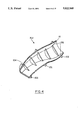
- FIG. 1 shows mandrel 10 having T-stiffeners for sealing off its outer surface and for aligning, joining and fastening mandrel quarter sections 12, 14, 16, 18.
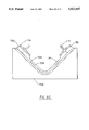
- FIG. 2 is a cross section of a T-shaped stiffener of this invention.
- FIG. 3 shows master splash used in making the female splash for the mandrel quarter sections of this invention.
- FIG. 4 shows a mandrel quarter section (shown in FIG. 1) carried within a female splash section used in forming it.
- FIGS. 5a, b, c shows bulkhead fabrication.
- FIG. 6 shows a disassembled mandrel
- FIGS. 7A, B, C and 8A, B, C show preparation of a T-stiffener of this invention.
- FIG. 9 shows airduct 900 with its clamshells for curing in an autoclave.
- FIG. 1 schematically depicts mandrel 10 of this invention.
- Mandrel 10 is made from four contoured quarter sections 12, 14, 16 and 18 which form the surface of mandrel 10.
- Quarter sections 12, 14, 16 and 18 are made of composite comprising carbon fiber or other high strength filaments in a thermoset matrix but the sections could also be machined metal or monolithic graphite.
- the matrix of quarter sections 12, 14, 16 and 18 has been cured at room temperature after prepreg lay-up but such sections may be made using filament winding or lay-up of prepregs that incorporate resins that cure at higher temperatures, e.g. 250° F.
- Quarter sections made of these materials provide the surfaces of mandrel 10 with a coefficient of thermal expansion approximating the coefficient of thermal expansion of the part being fabricated on mandrel 10 more closely than metal.
- Mandrel 10 further comprises steel shaft 20, bulkhead 22 and T-stiffener 24.
- T-stiffeners 24 shown in FIG. 1 rigidly mount to bulkhead 22 through clamps (not shown) respectively fastening to bulkhead 22.
- Bulkhead 22 rigidly mounts around shaft 20 for rotation of quarter sections 12, 14, 16 and 18 of mandrel 10.
- FIG. 2 shows in cross-section T-stiffener 24 fastened to quarter sections 16, 18 of mandrel 10.
- T-stiffener 24 extends continuously along the length of putty filled seam 35 between quarter sections 16, 18; and it comprises leg 26 that is integral with spans 32, 34 and projects inwardly into mandrel 10.
- Spans 32, 34 respectively bolt to quarter sections 16, 18 by fasteners 28, 29 and have grooves 36, 38.
- Rubber o-rings 40, 42 fit into respective grooves 36, 38 of T-stiffener 24. Rubber o-rings 40, 42 seal the surface 43 inside of mandrel 10 (where T-stiffener 24 resides) from outer surface 44 of mandrel 10.
- the O-rings are shown generally cylinderical bodies in the rectilinear cross-section of grooves 36, 38 but may have any geometry suitable for sealing the mandrel sections and T-stiffener. Filler putty 46 also acts to smooth seam 35 between quarter sections 16, 18.
- T-stiffeners used in constructing mandrel 10 are layed up on female master splashes.
- silicone rubber strips are placed on the female tools for molding grooves 36, 38 in T-stiffener 24 (see FIG. 2). Rectangular lengths of prepreg are layed upon each other in making the T-stiffener. Additional prepreg tow that is long and narrow is used in filling corners.
- the T-stiffener is cured, removed from its master splash as an integral composite body and machined to final dimensions. Fabrication of T-stiffeners is described more fully in connection with FIGS. 7A and 7B.
- Sections 12, 14, 16 and 18 of mandrel 10 are made starting with a female master splash made from the master model (see FIGS. 7A) of the part being fabricated.
- FIG. 3 shows female master splash 100 which has been fabricated using this master model 107.
- Female master splash 100 breaks into four quarter sections.
- Splash supports 102 hold the splash shape and enable each of quarter sections forming splash 100 to stand on the floor or other surface while a mandrel quarter section (such as shown in FIG. 4) is fabricated.
- the quarter sections are preferably fabricated individually in their respective female splashes. For example, carbon fiber containing prepreg cut to desired lengths and widths is layed into the female splash and cured. When room temperature curing matrix resins are employed, the quarter section carried in the splash may be cured on the shop floor.
- FIG. 4 depicts schematically mandrel quarter section 18 within a quarter section of female splash section 702. Gussets 104, added to female quarter section 18 after lay-up and initial cure thereof, assist stabilizing the shape of quarter section 18 during cure. Previously fabricated T-stiffeners (not shown) are positioned along edges 106 of section 18 for shaping the contour of these edge to the T-stiffener surface. Quarter section 18, after being cured in female splash 702, is trimmed to length and the edges 106 machined to their defined configurations for joining with quarter sections 12 and 16 made in similar fashion.
- FIG. 5 shows the procedure by which the bulkheads (such as 22, FIG. 1) and gussets, by analogy, if desired, are fabricated.
- Prepregs made of carbon fiber or the like are first layed-up as shown in FIG. 5(a), compacted under vacuum as shown in FIG. 5(b) and cured and then machined to final dimensions as shown in FIG. 5(c).
- prepregs 500 may be precut to desired dimensions before curing.
- FIG. 6 illustrates a cured aircraft structure, air duct 602 and disassembled mandrel components of this invention.
- FIG. 6 shows cured aircraft duct 602 from which composite mandrel quarter section 604 (other quarter sections not shown), rabbit race 606, T-stiffener 608 (other three T-stiffeners not shown), shaft 610 and bulkheads 614 and 616 have been disassembled and withdrawn. (As seen in FIG. 6, T-stiffener 608 has been fabricated to extend the length of the mandrel.)
- FIGS. 7A and 7B diagramatically illustrate in developed views and, FIGS. 8A and 8B illustrate also as developed views, procedures and techniques involved in making the T-stiffeners of this invention.
- FIG. 7A shows master model 700 in idealized cross section cut perpendicularly through its central longitudinal axis along with its associated female splashes 702, 704, 706 and 708. These splashes (a) have respective surfaces 703, 705, 707 and 709 contoured to those on the master model 700 and respective splash supports 702', 704', 706' and 708' (splashes 702, 704, 706 and 708 are used in fabricating mandrel quarter sections 12, 14, 16 and 18, e.g., splash 702 may be seen in FIG. 4).
- FIG. 7B shows in diagramatic cross section splash 706 standing on splash support 706'.
- Splash 706 has extension 710 used in lay-up of T-stiffener 712.
- T-stiffeners 712 and 714 may be fabricated using but one splash 706 with the aid of extensions 710 and 716 added to splash 706. (In alternate embodiments shown in FIG. 8C, the T-stiffeners are fabricated within a mandrel quarter section, rather than, as shown in FIG. 8A, within a splash used in fabricating a quarter section.)
- either mandrel extensions 720 and 721 can be used or two mandrel sections are fitted together and temporarily joined together, to provide a surface for forming the T-stiffener. If extensions 720 and 721 are used, they are cut from the mandrel quarter section 18 after the T-stiffeners 712 and 714 have been layed up and cured.
- the edges of the mandrel quarter section 18 under the T-stiffeners are made thicker as shown in FIG. 8C.
- the thicker edges allow for bolts having greater purchase to be inserted through the respective spans of the T-stiffeners.
- FIG. 8B illustrates prepreg lay-up of T-stiffener 712.
- T-stiffener as is seen in FIG. 8B has precured, vertical composite 800 which is a thin cured graphite sheet acting as to support uncured prepreg strips 802, 804 layed up against both of its surfaces.
- spans 806, 808 comprise uncured prepreg strips which are layed on the respective surfaces of extension 710 and splash 706.
- double back teflon tape sections 810, 812 are placed parallel along, but spaced from, seam 809 between extension 710 and splash 706.
- silicone rubber strips 814, 816 built to form, after their removal, grooves such as 36, 38 of the T-stiffener shown in FIG. 2.
- strips 814, 816 are layed along and parallel to seam 809 the length of the splash and extension, uncured prepreg strips, butt jointed, are layed over the splash and extension surfaces as well as over built up rubber strips 814, 816.
- lay-up of uncured prepreg 818, 820 forming spans 806, 808 preferably precedes lay-up of the prepreg 802, 804 of T-stiffener leg 801.
- a portion of uncured prepreg is layed across both spans 806, 808 to form a base for precured sheet 800.
- Twisted prepreg tows 822 are used to fill gaps around the corners around built-up rubber strips 814, 816.
- span 706 and extension 710 carrying the layed up stiffener is cured under heat and pressure.
- Extension 710 is then separated and rubber strips 814, 816 then removed to open the respective grooves in the T-stiffener 712.
- FIG. 9 shows uncured air duct 900 comprising skin 902 and staged stiffeners 904.
- Skin 902 has been made by fiber placement on mandrel quarter sections 906, 908, 910, 912 which are mounted around mandrel shaft 914.
- Bulkheads such as 916 (others not shown) mount to shaft 914 and four T-shaped stiffeners 918 which in turn are respectively bolted (not shown) to edges of adjacent quarter sections at 906, 908, 910, 912.
- T-stiffeners extend the entire length of the quarter sections in aligning, sealing and fastening together the adjacent quarter sections.
- Staged stiffeners 904 are prepared separately in uncured form from prepreg (tows, comprising a multitude of filaments, which are combined with thermosetting resin into a sheet prior to lay-up) or more preferably by fiber placement using tows impregnated with thermosetting resin and combined with other tows during preferred fiber placement. Staged stiffeners 904 are then aligned on skin 902.
- Clamshell halves 920, 922 molded to fit around duct 900 fasten together in sealed relation for curing duct 900 in an autoclave.
- Clamshell halves 920, 922 have a vacuum port connected to one or both of halves 920, 922 so as to allow evacuation and removal of volatiles during cure of duct 900.
- Halves 920, 922 are fabricated from composite with a skin thickness thin enough to allow reduction of pressure in clamshells 920, 922 to cause molding of the clamshell skin to the outer surface of duct 902.
- An open-ended cylindrical shaped bag (not shown) can surround duct 900 with its ends taped down within the quarter sections for sealing off the outer surfaces of skin 902 and stiffeners 904.
- Curing in the autoclave is at pressures up to 200 psi but more commonly at pressures up to 100 psi. Curing is preferably in stages using epoxy, maleimide or the like resins well known in the art. Curing temperatures range up to 400° C. but may be higher or lower without distracting from this invention.
Abstract
Description
Claims (7)
Priority Applications (5)
| Application Number | Priority Date | Filing Date | Title |
|---|---|---|---|
| US07/343,453 US5022845A (en) | 1989-04-25 | 1989-04-25 | Segmented mandrel for forming composite articles |
| CA002014981A CA2014981A1 (en) | 1989-04-25 | 1990-04-19 | Composite mandrel joints |
| EP90107687A EP0394934A1 (en) | 1989-04-25 | 1990-04-24 | Composite mandrel joints |
| JP2109960A JPH02299820A (en) | 1989-04-25 | 1990-04-25 | Divided mandrel |
| US07/604,548 US5173315A (en) | 1989-04-25 | 1990-10-25 | Tool for joining a segmented mandrel for forming composite articles |
Applications Claiming Priority (1)
| Application Number | Priority Date | Filing Date | Title |
|---|---|---|---|
| US07/343,453 US5022845A (en) | 1989-04-25 | 1989-04-25 | Segmented mandrel for forming composite articles |
Related Child Applications (1)
| Application Number | Title | Priority Date | Filing Date |
|---|---|---|---|
| US07/604,548 Division US5173315A (en) | 1989-04-25 | 1990-10-25 | Tool for joining a segmented mandrel for forming composite articles |
Publications (1)
| Publication Number | Publication Date |
|---|---|
| US5022845A true US5022845A (en) | 1991-06-11 |
Family
ID=23346187
Family Applications (1)
| Application Number | Title | Priority Date | Filing Date |
|---|---|---|---|
| US07/343,453 Expired - Lifetime US5022845A (en) | 1989-04-25 | 1989-04-25 | Segmented mandrel for forming composite articles |
Country Status (4)
| Country | Link |
|---|---|
| US (1) | US5022845A (en) |
| EP (1) | EP0394934A1 (en) |
| JP (1) | JPH02299820A (en) |
| CA (1) | CA2014981A1 (en) |
Cited By (25)
| Publication number | Priority date | Publication date | Assignee | Title |
|---|---|---|---|---|
| US5387098A (en) * | 1992-04-23 | 1995-02-07 | The Boeing Company | Flexible reusable mandrels |
| US5780075A (en) * | 1993-12-20 | 1998-07-14 | Institut Francais Du Petrole | Mandrel for filament winding - application to the manufacture of curved profiles |
| US5950965A (en) * | 1997-07-17 | 1999-09-14 | Lockheed Martin Corporation | Split shell spacecraft |
| US6245275B1 (en) * | 1999-05-13 | 2001-06-12 | Vought Aircraft Industries, Inc. | Method for fabricating composite structures |
| US6793479B1 (en) | 1998-04-17 | 2004-09-21 | Alliant Techsystems Inc. | Remotely actuated localized pressure and heat apparatus and method of use |
| US20060145049A1 (en) * | 2004-12-01 | 2006-07-06 | The Boeing Company | Segmented flexible barrel lay-up mandrel |
| US20070062022A1 (en) * | 2005-09-21 | 2007-03-22 | Rohr, Inc. | Method and apparatus for making a tubular composite structure |
| US20070261788A1 (en) * | 2006-04-04 | 2007-11-15 | Steven Stenard | Composite mandrel |
| US20080302486A1 (en) * | 2007-06-06 | 2008-12-11 | Airbus Uk Limited | Fibre placement tool |
| US20090236779A1 (en) * | 2008-03-21 | 2009-09-24 | Rohr, Inc. | Apparatus and Method for Making a Tubular Composite Barrel |
| US20100032862A1 (en) * | 2006-10-23 | 2010-02-11 | Constructions Industrielles De La Mediterranee Cnim | Composite tool for molding cylindrical parts |
| US20100109208A1 (en) * | 2008-11-03 | 2010-05-06 | Claude Marc Hubert | Multi-segment tool and method for composite formation |
| US20110014419A1 (en) * | 2008-03-20 | 2011-01-20 | Hexcel Composites, Ltd. | Prepregs |
| US20120039720A1 (en) * | 2009-01-21 | 2012-02-16 | Vestas Wind Systems A/S | Method of manufacturing a wind turbine blade by embedding a layer of pre-cured fibre reinforced resin |
| US20120112377A1 (en) * | 2008-06-13 | 2012-05-10 | Advanced Composites Group Limited | Tool and method for the manufacture of composite structures |
| US20120175807A1 (en) * | 2010-12-23 | 2012-07-12 | Gamesa Innovation & Technology, S.L. | Partitioned shell mold for wind turbine blades, its manufacturing method, and blade production method employing this mold |
| US20130087955A1 (en) * | 2010-04-20 | 2013-04-11 | Snecma | Device for manufacturing a casing made of a composite material and manufacturing method using such a device |
| JP2013212686A (en) * | 2012-03-30 | 2013-10-17 | Alenia Aermacchi Spa | Positioning system of sector of device for manufacturing airplane fuselage |
| JP2013212685A (en) * | 2012-03-30 | 2013-10-17 | Alenia Aermacchi Spa | Constraint system of sector of device for manufacturing airplane fuselage |
| US20180056611A1 (en) * | 2016-08-23 | 2018-03-01 | Textron Aviation Inc. | Nested manufacturing of composite structures |
| CN108407220A (en) * | 2018-04-28 | 2018-08-17 | 深圳市凯中精密技术股份有限公司 | A kind of positioning component and injection mold of mold |
| US10994447B2 (en) * | 2016-12-01 | 2021-05-04 | Kawasaki Jukogyo Kabushiki Kaisha | Seal structure of mold for manufacturing composite material structure |
| US20220055260A1 (en) * | 2020-06-29 | 2022-02-24 | Thermwood Corporation | Systems and methods for producing parts at elevated temperatures |
| US11446846B2 (en) * | 2018-02-01 | 2022-09-20 | Lm Wind Power International Technology Ii Aps | Connection of mould parts |
| CN108407220B (en) * | 2018-04-28 | 2024-04-26 | 深圳市凯中精密技术股份有限公司 | Positioning assembly of mold and injection mold |
Families Citing this family (2)
| Publication number | Priority date | Publication date | Assignee | Title |
|---|---|---|---|---|
| DE102010053635B4 (en) * | 2010-12-07 | 2017-05-11 | Hero Gmbh | Process for producing a fiber composite product |
| US9523431B2 (en) * | 2013-05-31 | 2016-12-20 | The Boeing Company | Sealing and testing segmented tools |
Citations (11)
| Publication number | Priority date | Publication date | Assignee | Title |
|---|---|---|---|---|
| US1001500A (en) * | 1910-04-16 | 1911-08-22 | Robert Oscar Blayney | Adjustable form for building tubular structures. |
| US2808097A (en) * | 1954-07-12 | 1957-10-01 | Smith Corp A O | Apparatus for fabricating a fiber reinforced storage structure |
| US3279741A (en) * | 1965-07-19 | 1966-10-18 | Long Construction Co | Expandable core-former |
| US3279739A (en) * | 1965-07-19 | 1966-10-18 | Long Construction Co | Expandable core-former |
| US3345693A (en) * | 1965-01-27 | 1967-10-10 | Thiokol Chemical Corp | Apparatus for forming ignition surfaces in solid propellant motors |
| US3652024A (en) * | 1969-11-26 | 1972-03-28 | Us Air Force | Mandrels |
| US4213641A (en) * | 1977-12-29 | 1980-07-22 | Owens-Corning Fiberglas Corporation | Filament wound pipe coupling |
| US4288277A (en) * | 1979-07-17 | 1981-09-08 | Lembit Siilats | Molding system with retracting mold |
| US4364894A (en) * | 1980-04-21 | 1982-12-21 | Sekisui Kagaku Kogyo Kabushiki Kaisha | Method for molding a reinforced plastic tubular body having a socket, and mold therefore |
| US4448628A (en) * | 1982-07-14 | 1984-05-15 | Stott Rexeene S | Segmental mandrel for making wound filament structures |
| US4717330A (en) * | 1983-11-17 | 1988-01-05 | Messerschmitt-Boelkow-Blohm Gesellschaft Mit Beschraenkter Haftung | Apparatus for making a structural component |
Family Cites Families (2)
| Publication number | Priority date | Publication date | Assignee | Title |
|---|---|---|---|---|
| FR2172548A5 (en) * | 1972-02-17 | 1973-09-28 | Plastrex Manurhin Sarl | |
| US4278490A (en) * | 1979-12-21 | 1981-07-14 | Owens-Corning Fiberglas Corporation | Sleeve for changing diameter of collapsible mandrel |
-
1989
- 1989-04-25 US US07/343,453 patent/US5022845A/en not_active Expired - Lifetime
-
1990
- 1990-04-19 CA CA002014981A patent/CA2014981A1/en not_active Abandoned
- 1990-04-24 EP EP90107687A patent/EP0394934A1/en not_active Withdrawn
- 1990-04-25 JP JP2109960A patent/JPH02299820A/en active Pending
Patent Citations (11)
| Publication number | Priority date | Publication date | Assignee | Title |
|---|---|---|---|---|
| US1001500A (en) * | 1910-04-16 | 1911-08-22 | Robert Oscar Blayney | Adjustable form for building tubular structures. |
| US2808097A (en) * | 1954-07-12 | 1957-10-01 | Smith Corp A O | Apparatus for fabricating a fiber reinforced storage structure |
| US3345693A (en) * | 1965-01-27 | 1967-10-10 | Thiokol Chemical Corp | Apparatus for forming ignition surfaces in solid propellant motors |
| US3279741A (en) * | 1965-07-19 | 1966-10-18 | Long Construction Co | Expandable core-former |
| US3279739A (en) * | 1965-07-19 | 1966-10-18 | Long Construction Co | Expandable core-former |
| US3652024A (en) * | 1969-11-26 | 1972-03-28 | Us Air Force | Mandrels |
| US4213641A (en) * | 1977-12-29 | 1980-07-22 | Owens-Corning Fiberglas Corporation | Filament wound pipe coupling |
| US4288277A (en) * | 1979-07-17 | 1981-09-08 | Lembit Siilats | Molding system with retracting mold |
| US4364894A (en) * | 1980-04-21 | 1982-12-21 | Sekisui Kagaku Kogyo Kabushiki Kaisha | Method for molding a reinforced plastic tubular body having a socket, and mold therefore |
| US4448628A (en) * | 1982-07-14 | 1984-05-15 | Stott Rexeene S | Segmental mandrel for making wound filament structures |
| US4717330A (en) * | 1983-11-17 | 1988-01-05 | Messerschmitt-Boelkow-Blohm Gesellschaft Mit Beschraenkter Haftung | Apparatus for making a structural component |
Cited By (51)
| Publication number | Priority date | Publication date | Assignee | Title |
|---|---|---|---|---|
| US5387098A (en) * | 1992-04-23 | 1995-02-07 | The Boeing Company | Flexible reusable mandrels |
| US5780075A (en) * | 1993-12-20 | 1998-07-14 | Institut Francais Du Petrole | Mandrel for filament winding - application to the manufacture of curved profiles |
| US5950965A (en) * | 1997-07-17 | 1999-09-14 | Lockheed Martin Corporation | Split shell spacecraft |
| US6793479B1 (en) | 1998-04-17 | 2004-09-21 | Alliant Techsystems Inc. | Remotely actuated localized pressure and heat apparatus and method of use |
| US6245275B1 (en) * | 1999-05-13 | 2001-06-12 | Vought Aircraft Industries, Inc. | Method for fabricating composite structures |
| US20060145049A1 (en) * | 2004-12-01 | 2006-07-06 | The Boeing Company | Segmented flexible barrel lay-up mandrel |
| US7166251B2 (en) * | 2004-12-01 | 2007-01-23 | The Boeing Company | Segmented flexible barrel lay-up mandrel |
| US7861394B2 (en) | 2005-09-21 | 2011-01-04 | Rohr, Inc. | Method for making a tubular composite structure |
| US7707708B2 (en) | 2005-09-21 | 2010-05-04 | Rohr, Inc. | Apparatus for making a tubular composite structure |
| US20070062022A1 (en) * | 2005-09-21 | 2007-03-22 | Rohr, Inc. | Method and apparatus for making a tubular composite structure |
| US20100170633A1 (en) * | 2005-09-21 | 2010-07-08 | Rohr, Inc. | Method and Apparatus for Making a Tubular Composite Structure |
| US7815160B2 (en) | 2006-04-04 | 2010-10-19 | A & P Technology | Composite mandrel |
| US20070261788A1 (en) * | 2006-04-04 | 2007-11-15 | Steven Stenard | Composite mandrel |
| US20100032862A1 (en) * | 2006-10-23 | 2010-02-11 | Constructions Industrielles De La Mediterranee Cnim | Composite tool for molding cylindrical parts |
| US8382467B2 (en) * | 2006-10-23 | 2013-02-26 | Constructions Industrielles de la Mediterranee—CNIM | Multiple part mandrel |
| US20080302486A1 (en) * | 2007-06-06 | 2008-12-11 | Airbus Uk Limited | Fibre placement tool |
| US8490269B2 (en) * | 2007-06-06 | 2013-07-23 | Airbus Operations Limited | Fibre placement tool |
| US8043457B2 (en) * | 2007-06-06 | 2011-10-25 | Airbus Operations Limited | Fibre placement tool |
| US20120030922A1 (en) * | 2007-06-06 | 2012-02-09 | Airbus Operations Limited | Fibre placement tool |
| US9174394B2 (en) * | 2008-03-20 | 2015-11-03 | Hexcel Composites Limited | Prepregs |
| US20110014419A1 (en) * | 2008-03-20 | 2011-01-20 | Hexcel Composites, Ltd. | Prepregs |
| US20100059185A1 (en) * | 2008-03-21 | 2010-03-11 | Rohr, Inc. | Apparatus and Method for Making a Tubular Composite Barrel |
| US7640961B2 (en) * | 2008-03-21 | 2010-01-05 | Rohr, Inc. | Apparatus and method for making a tubular composite barrel |
| US20090236779A1 (en) * | 2008-03-21 | 2009-09-24 | Rohr, Inc. | Apparatus and Method for Making a Tubular Composite Barrel |
| US8012286B2 (en) | 2008-03-21 | 2011-09-06 | Rohr, Inc. | Apparatus and method for making a tubular composite barrel |
| US20120112377A1 (en) * | 2008-06-13 | 2012-05-10 | Advanced Composites Group Limited | Tool and method for the manufacture of composite structures |
| US9975299B2 (en) * | 2008-06-13 | 2018-05-22 | Cytec Industrial Materials (Derby) Limited | Tool and method for the manufacture of composite structures |
| US20170225410A1 (en) * | 2008-06-13 | 2017-08-10 | Cytec Industrial Materials (Derby) Limited | Tool and method for the manufacture of composite structures |
| US9662843B2 (en) * | 2008-06-13 | 2017-05-30 | Cytec Industrial Materials (Derby) Limited | Tool and method for the manufacture of composite structures |
| USRE46321E1 (en) | 2008-11-03 | 2017-02-28 | Rohr, Inc. | Multi-segment tool and method for composite formation |
| US8394315B2 (en) | 2008-11-03 | 2013-03-12 | Rohr, Inc. | Multi-segment tool and method for composite formation |
| US8025499B2 (en) | 2008-11-03 | 2011-09-27 | Rohr, Inc. | Multi-segment tool and method for composite formation |
| US20100109208A1 (en) * | 2008-11-03 | 2010-05-06 | Claude Marc Hubert | Multi-segment tool and method for composite formation |
| US20120039720A1 (en) * | 2009-01-21 | 2012-02-16 | Vestas Wind Systems A/S | Method of manufacturing a wind turbine blade by embedding a layer of pre-cured fibre reinforced resin |
| US10590909B2 (en) | 2009-01-21 | 2020-03-17 | Vestas Wind Systems A/S | Method of manufacturing a wind turbine blade by embedding a layer of pre-cured fibre reinforced resin |
| US9073270B2 (en) * | 2009-01-21 | 2015-07-07 | Vestas Wind Systems A/S | Method of manufacturing a wind turbine blade by embedding a layer of pre-cured fibre reinforced resin |
| US20130087955A1 (en) * | 2010-04-20 | 2013-04-11 | Snecma | Device for manufacturing a casing made of a composite material and manufacturing method using such a device |
| US9399315B2 (en) * | 2010-04-20 | 2016-07-26 | Snecma | Device for manufacturing a casing made of a composite material and manufacturing method using such a device |
| US8951457B2 (en) * | 2010-12-23 | 2015-02-10 | Gamesa Innovation & Technology, S.L. | Partitioned shell mold for wind turbine blades, its manufacturing method, and blade production method employing this mold |
| US20120175807A1 (en) * | 2010-12-23 | 2012-07-12 | Gamesa Innovation & Technology, S.L. | Partitioned shell mold for wind turbine blades, its manufacturing method, and blade production method employing this mold |
| JP2013212685A (en) * | 2012-03-30 | 2013-10-17 | Alenia Aermacchi Spa | Constraint system of sector of device for manufacturing airplane fuselage |
| JP2013212686A (en) * | 2012-03-30 | 2013-10-17 | Alenia Aermacchi Spa | Positioning system of sector of device for manufacturing airplane fuselage |
| US20180056611A1 (en) * | 2016-08-23 | 2018-03-01 | Textron Aviation Inc. | Nested manufacturing of composite structures |
| US11331867B2 (en) * | 2016-08-23 | 2022-05-17 | Textron Innovations, Inc. | Nested manufacturing of composite structures |
| US10994447B2 (en) * | 2016-12-01 | 2021-05-04 | Kawasaki Jukogyo Kabushiki Kaisha | Seal structure of mold for manufacturing composite material structure |
| US11446846B2 (en) * | 2018-02-01 | 2022-09-20 | Lm Wind Power International Technology Ii Aps | Connection of mould parts |
| US11685081B2 (en) | 2018-02-01 | 2023-06-27 | Lm Wind Power International Technology Ii Aps | Connection of mould parts |
| CN108407220A (en) * | 2018-04-28 | 2018-08-17 | 深圳市凯中精密技术股份有限公司 | A kind of positioning component and injection mold of mold |
| CN108407220B (en) * | 2018-04-28 | 2024-04-26 | 深圳市凯中精密技术股份有限公司 | Positioning assembly of mold and injection mold |
| US20220055260A1 (en) * | 2020-06-29 | 2022-02-24 | Thermwood Corporation | Systems and methods for producing parts at elevated temperatures |
| US11931932B2 (en) * | 2020-06-29 | 2024-03-19 | Thermwood Corporation | Systems and methods for producing parts at elevated temperatures |
Also Published As
| Publication number | Publication date |
|---|---|
| EP0394934A1 (en) | 1990-10-31 |
| CA2014981A1 (en) | 1990-10-25 |
| JPH02299820A (en) | 1990-12-12 |
Similar Documents
| Publication | Publication Date | Title |
|---|---|---|
| US5022845A (en) | Segmented mandrel for forming composite articles | |
| US4780262A (en) | Method for making composite structures | |
| EP0650825B1 (en) | Method for forming a unitary fibre-reinforced composite panel structure | |
| US4693678A (en) | Male layup-female molding system for fabricating reinforced composite structures | |
| US5368807A (en) | Method for vacuum bag molding fiber reinforced resin matrix composites | |
| EP0491651B1 (en) | The method of fabricating a complex part made of composite material | |
| US5346367A (en) | Advanced composite rotor blade | |
| US10464239B2 (en) | System for manufacturing monolithic structures using expanding internal tools | |
| US5683646A (en) | Fabrication of large hollow composite structure with precisely defined outer surface | |
| US6632502B1 (en) | Method for fabricating an advanced composite aerostructure article having an integral co-cured fly away hollow mandrel | |
| EP1231046B1 (en) | Method for manufacturing elements of composite materials by the cobonding technique | |
| EP1070661B1 (en) | Wing of composite material and method of fabricating the same | |
| US4863771A (en) | Hollow fiber reinforced structure and method of making same | |
| US5137071A (en) | Apparatus for forming a composite structure | |
| EP1754590B1 (en) | Method for the manufacture of a composite article comprising a fitting element and article obtained thereby | |
| EP1074466B1 (en) | Method of fabricating a composite material wing | |
| US5833786A (en) | Titanium radius filler for use in composite interfaces | |
| US8394315B2 (en) | Multi-segment tool and method for composite formation | |
| CA2278693C (en) | Method and apparatus for manufacturing composite structures | |
| EP0904929B1 (en) | Method for forming a caul plate during moulding of a part | |
| US4251309A (en) | Method of making rotor blade root end attachment | |
| CA1247318A (en) | Method of forming a fiber reinforced composite article of complex configuration | |
| US5173315A (en) | Tool for joining a segmented mandrel for forming composite articles | |
| JPS6271617A (en) | Fiber-reinforced hollow structure and manufacture thereof | |
| JPS6228742B2 (en) |
Legal Events
| Date | Code | Title | Description |
|---|---|---|---|
| AS | Assignment |
Owner name: HERCULES INCORPORATED, DELAWARE Free format text: ASSIGNMENT OF ASSIGNORS INTEREST.;ASSIGNORS:CHARLSON, SANDRA M.;KOTULA, STEVEN J.;MC CLOY, MICHAEL R.;REEL/FRAME:005094/0140;SIGNING DATES FROM 19890512 TO 19890516 |
|
| STCF | Information on status: patent grant |
Free format text: PATENTED CASE |
|
| FPAY | Fee payment |
Year of fee payment: 4 |
|
| SULP | Surcharge for late payment | ||
| REMI | Maintenance fee reminder mailed | ||
| FEPP | Fee payment procedure |
Free format text: PAYOR NUMBER ASSIGNED (ORIGINAL EVENT CODE: ASPN); ENTITY STATUS OF PATENT OWNER: LARGE ENTITY |
|
| FPAY | Fee payment |
Year of fee payment: 8 |
|
| AS | Assignment |
Owner name: CHASE MANHATTAN BANK, THE, NEW YORK Free format text: PATENT SECURITY AGREEMENT;ASSIGNOR:ALLIANT TECHSYSTEMS INC.;REEL/FRAME:009662/0089 Effective date: 19981124 |
|
| AS | Assignment |
Owner name: ALLIANT TECHSYSTEMS INC., MINNESOTA Free format text: ASSIGNMENT OF ASSIGNORS INTEREST;ASSIGNOR:HERCULES INCORPORATED;REEL/FRAME:009845/0641 Effective date: 19990323 |
|
| FPAY | Fee payment |
Year of fee payment: 12 |
|
| AS | Assignment |
Owner name: ALLIANT TECHSYSTEMS INC., MINNESOTA Free format text: SECURITY INTEREST;ASSIGNOR:JPMORGAN CHASE BANK (FORMERLY KNOWN AS THE CHASE MANHATTAN BANK);REEL/FRAME:015201/0351 Effective date: 20040331 |
|
| AS | Assignment |
Owner name: BANK OF AMERICA, N.A., NORTH CAROLINA Free format text: SECURITY INTEREST;ASSIGNORS:ALLIANT TECHSYSTEMS INC.;ALLANT AMMUNITION AND POWDER COMPANY LLC;ALLIANT AMMUNITION SYSTEMS COMPANY LLC;AND OTHERS;REEL/FRAME:014692/0653 Effective date: 20040331 |