US7084390B2 - Position-measuring device including measuring graduation and scanning unit - Google Patents
Position-measuring device including measuring graduation and scanning unit Download PDFInfo
- Publication number
- US7084390B2 US7084390B2 US10/921,452 US92145204A US7084390B2 US 7084390 B2 US7084390 B2 US 7084390B2 US 92145204 A US92145204 A US 92145204A US 7084390 B2 US7084390 B2 US 7084390B2
- Authority
- US
- United States
- Prior art keywords
- detector
- extension direction
- groups
- detector groups
- along
- Prior art date
- Legal status (The legal status is an assumption and is not a legal conclusion. Google has not performed a legal analysis and makes no representation as to the accuracy of the status listed.)
- Expired - Lifetime, expires
Links
- 238000001514 detection method Methods 0.000 claims abstract description 54
- 238000011156 evaluation Methods 0.000 claims abstract description 22
- 230000000737 periodic effect Effects 0.000 claims description 14
- 230000000295 complement effect Effects 0.000 claims description 12
- 238000006073 displacement reaction Methods 0.000 claims description 11
- 238000001914 filtration Methods 0.000 description 39
- 239000002131 composite material Substances 0.000 description 5
- 238000012986 modification Methods 0.000 description 4
- 230000004048 modification Effects 0.000 description 4
- 230000015572 biosynthetic process Effects 0.000 description 2
- 238000000034 method Methods 0.000 description 2
- 238000013459 approach Methods 0.000 description 1
- 238000010276 construction Methods 0.000 description 1
- 238000013461 design Methods 0.000 description 1
- 238000011161 development Methods 0.000 description 1
- 238000012545 processing Methods 0.000 description 1
- 230000035945 sensitivity Effects 0.000 description 1
- 238000007493 shaping process Methods 0.000 description 1
Images


Classifications
-
- G—PHYSICS
- G01—MEASURING; TESTING
- G01D—MEASURING NOT SPECIALLY ADAPTED FOR A SPECIFIC VARIABLE; ARRANGEMENTS FOR MEASURING TWO OR MORE VARIABLES NOT COVERED IN A SINGLE OTHER SUBCLASS; TARIFF METERING APPARATUS; MEASURING OR TESTING NOT OTHERWISE PROVIDED FOR
- G01D5/00—Mechanical means for transferring the output of a sensing member; Means for converting the output of a sensing member to another variable where the form or nature of the sensing member does not constrain the means for converting; Transducers not specially adapted for a specific variable
- G01D5/26—Mechanical means for transferring the output of a sensing member; Means for converting the output of a sensing member to another variable where the form or nature of the sensing member does not constrain the means for converting; Transducers not specially adapted for a specific variable characterised by optical transfer means, i.e. using infrared, visible, or ultraviolet light
- G01D5/32—Mechanical means for transferring the output of a sensing member; Means for converting the output of a sensing member to another variable where the form or nature of the sensing member does not constrain the means for converting; Transducers not specially adapted for a specific variable characterised by optical transfer means, i.e. using infrared, visible, or ultraviolet light with attenuation or whole or partial obturation of beams of light
- G01D5/34—Mechanical means for transferring the output of a sensing member; Means for converting the output of a sensing member to another variable where the form or nature of the sensing member does not constrain the means for converting; Transducers not specially adapted for a specific variable characterised by optical transfer means, i.e. using infrared, visible, or ultraviolet light with attenuation or whole or partial obturation of beams of light the beams of light being detected by photocells
- G01D5/347—Mechanical means for transferring the output of a sensing member; Means for converting the output of a sensing member to another variable where the form or nature of the sensing member does not constrain the means for converting; Transducers not specially adapted for a specific variable characterised by optical transfer means, i.e. using infrared, visible, or ultraviolet light with attenuation or whole or partial obturation of beams of light the beams of light being detected by photocells using displacement encoding scales
- G01D5/34707—Scales; Discs, e.g. fixation, fabrication, compensation
- G01D5/34715—Scale reading or illumination devices
Definitions
- the present invention relates to a position-measuring device and to a scanning unit.
- a position-measuring device of this type includes a linear or curved measuring graduation extending along a measuring direction, a scanning unit for scanning the measuring graduation, as well as a detection device of the scanning unit that includes a plurality of detector elements which are positioned periodically one after the other along an extension direction and which, during the scanning of the measuring graduation, generate output signals able to be supplied to an evaluation unit.
- a plurality of adjacent detector elements of the detection device are interconnected to form in each case a detector group such that their output signals are joined and are able to be supplied as a unified signal to the evaluation unit.
- the measuring graduation having the coarser grating structure has the n-fold grating constant of the measuring graduation having the first, finer grating structure, then, for instance, in each case n-adjacent detector elements of the detection device are interconnected to form one detector group in order to scan the measuring graduation having the coarser grating constant using the same detection device.
- the measuring graduation is typically formed as a mark graduation in the form of a plurality of marks arranged, e.g., periodically, one after the other along the measuring direction.
- the measuring direction may be formed both by a straight line (linear position-measuring system) and by a curved, e.g., circularly extended line (in the case of a so-called rotary encoder or angular position measuring system).
- the detector elements are formed, for example, as photo elements which optically scan the measuring graduation and, in so doing, generate electrical output signals able to be supplied to an evaluation unit.
- the individual detector elements of the detection device of the scanning unit may be shaped in a conventional manner with respect to their geometric form such that when scanning the measuring graduation having the first, finer grating constant, a harmonics filtering operation is carried out. That is to say, by the selection of suitable contours for the detector elements, certain specifiable harmonics may be eliminated when scanning the measuring graduation having the smaller grating constant. However, if for scanning the coarser measuring graduation having the larger grating constant, in each case a plurality of adjacent detector elements are combined to form one detector group, then the output signal generated when scanning the coarser measuring graduation has a significant harmonics component that may interfere in the further processing and evaluation of the output signal. Reference is made to German Published Patent Application No. 195 05 176.
- An example embodiment of the present invention may provide a position-measuring device that may exhibit improved quality of the output signal of the detection device.
- the detector elements of the detection device may be combined to form detector groups, and they may be arranged one after the other along the extension direction so that at least one defined harmonic is eliminated from the output signals of the detection device.
- the design approach is based on the knowledge that harmonics may be eliminated from the output signals not only by a specific shaping of the detector elements, but also (utilizing certain filter functions) by a specific construction of the individual detector groups as well as by their arrangement.
- the individual detector elements are therefore combined to create suitable detector groups as a function of a selected filter function, with which specific, predefined harmonics are to be eliminated from the output signals.
- the grating constant of the, e.g., coarser, measuring graduation to be scanned may be an integral multiple of the smallest grating constant of the detection device, thus of the period of the arrangement of the individual detector elements without consideration of phases and interconnections of the detector elements.
- the detector groups set apart from each other in the extension direction of the detection device, that generate output signals of one phase (e.g., 0°, 90°, 180° or 270°, respectively) are interconnected, so that their output signals are supplied as a unified signal to the evaluation unit. That is to say, each detector group is assigned one output signal having a defined phase, and the detector groups whose output signal has the same phase are interconnected so that their output signals are supplied as a joint output signal to the evaluation unit.
- one phase e.g., 0°, 90°, 180° or 270°, respectively
- the number of detector elements making up the individual detector groups having output signals of one phase may vary, at least for a portion of the phases.
- the distance between adjacent detector elements of the same phase may vary.
- the detector groups may be arranged along the extension direction, e.g., in the manner that base units, each made up of a plurality of detector groups, are positioned one after the other (e.g., not periodically) along the extension direction.
- a base unit of the detection device should be understood to mean a unit having the minimal number of detector elements permitting the desired harmonics filtering.
- all detector groups of the detection device are positioned one after the other along one track.
- the detector groups are arranged along at least two tracks situated side by side, perpendicular to the extension direction of the detection device.
- the detector groups of one phase arranged in different tracks are displaced relative to each other by a specific displacement distance ⁇ x.
- d represents the grating constant of the measuring graduation to be scanned
- g f represents the smallest grating constant of the detection device (thus indicates its finest periodic raster formed by the individual detector elements)
- n represents the order of the harmonic to be filtered
- m represents a whole number
- i represents a natural number.
- all detector groups of one phase are arranged in one track, so that adjacent tracks each exclusively have detector groups of different phases.
- the detector groups of a first and a second phase e.g., 0° and 180°
- the detector groups of a third and a fourth phase e.g., 90° and 270°
- the detector groups of one phase may also be positioned partially in the one and partially in the other track.
- the distribution of the detector groups, from which signals of one phase are generated, not only along the measuring or extension direction of the detection device, but also on at least two adjacent tracks, may reduce the sensitivity of the arrangement to soiling. Moreover, in this case the resulting scanning signal may not be influenced by possible changes in the mark width of the scanned measuring graduation.
- the arrangement of the detector groups along the extension direction of the detection device is in each case determined by at least one generating filter function that indicates for each detector element, the adjacent detector elements with which it is to be interconnected to form a detector group.
- the arrangement of the detector groups along the extension direction is determined by the linkage of at least two generating filter functions that relate to different detector groups and/or to different features of a detector group. This may make it possible to achieve a particularly high filling factor in the detector arrangement resulting from the formation of detector groups, that is to say, the greatest possible number of the detector elements provided for scanning a finer scale with a small grating constant are utilized for forming the detector groups.
- the arrangement of the detector groups along the extension direction may be determined by the linkage of at least two complementary filter functions that relate to different detector groups and/or to different features of a detector group.
- complementary filter functions are those filter functions which complement each other with respect to the total filtering action in relation to specific stipulations, such as the minimization of the harmonic content of the output signal. Examples of suitable complementary filter functions are indicated below in the description of example embodiments.
- d represents the grating constant of the measuring graduation to be scanned
- g f represents the smallest grating constant of the periodic arrangement of detector elements
- n represents the harmonic to be filtered
- m represents a whole number
- i represents a natural number.
- Another filter function is characterized by the fact that the extension of interconnected, in-phase detector groups along the extension direction of the detection device varies, in that the individual, in-phase detector groups are in each case formed by a different number of detector elements.
- the average extension of the in-phase detector groups may correspond to the period of the fundamental wave of the output signals of the corresponding detector group.
- i, k represent natural numbers
- d represents the grating constant of the measuring graduation to be scanned
- g f represents the smallest grating constant of the periodic arrangement of the detector elements
- n represents the order of the harmonic to be filtered.
- the arrangement of the detector groups along the extension direction of the detection device may be determined by the linkage of a first generating filter function, according to which the spacing of the detector groups of the same phase varies in the extension direction, with a second generating filter function with which the extension of the detector groups along the extension direction is defined.
- i and N represent natural numbers and k represents a whole number having an amount less than or equal to 1.
- g f represents the smallest grating constant of the periodic arrangement of detector elements, and d represents the grating constant of the measuring graduation to be scanned.
- the first or the second arcsine function indicates the arrangement of those detector groups whose output signals have the phase 0° or 180°.
- Corresponding formulas apply for the location of the detector groups which generate output signals of the phase 90° or 270°.
- the expression k+0.25 or k+0.75 is to be used at the beginning of the corresponding term.
- the extension of the detector groups along the extension direction and/or perpendicular to the extension direction of the detection device is varied according to a trigonometric or cyclometric (inverse trigonometric) function, e.g., according to a sine, cosine, arcsine, arccosine function, etc. All harmonics (especially also for higher harmonics) may thereby be covered and filtered.
- detector elements arranged side by side perpendicular to the extension direction of the detection device are in each case interconnected to form detector groups such that specifiable harmonics may thereby be eliminated from the output signals.
- the extension of the detector groups perpendicular to the aforesaid extension direction may be varied, for example, according to a cosine function.
- a position-measuring device includes: a measuring graduation extending along a measuring direction; and a scanning unit configured to scan the measuring graduation, the scanning unit including a detection device, the detection device including a plurality of detector elements arranged periodically one after another along an extension direction, the detector elements configured to generate, during scanning of the measuring graduation, output signals suppliable to an evaluation unit, a plurality of adjacent detector elements interconnected to form a detector group and arranged to join output signals and to supply output signals as a unified signal to the evaluation unit, the detector groups arranged one after another along the extension direction to eliminate at least one defined harmonic from the output signals.
- a plurality of detector groups set apart from each other in the extension direction, may be interconnected to join output signals and to supply output signals as a unified signal to the evaluation unit.
- the interconnected detector groups may be configured to generate output signals of one phase.
- a number of detector elements of the detector groups of one phase may vary along the extension direction.
- Individual detector elements interconnected to form a detector group may be configured to filter at least one further harmonic that results from scanning of a measuring graduation having a different graduation period.
- the detector groups may be arranged along at least two tracks located side by side perpendicular to the extension direction.
- An arrangement of the detector groups along the extension direction may be in accordance with at least one generating filter function that, for each detector element, indicates with which adjacent detector elements the detector element is interconnected.
- the arrangement of the detector groups along the extension direction may be in accordance with a linkage of at least two generating filter functions that relate at least one of (a) to different detector groups and (b) to different features of a detector group.
- the arrangement of the detector groups along the extension direction may be in accordance with a linkage of at least two complementary filter functions that relate at least one of (a) to different detector groups and (b) to different features of a detector group.
- the detector groups of individual phases may be arranged in different tracks along the extension direction displaced relative to each other by a specific displacement distance.
- a distance between detector groups may vary along the extension direction to eliminate harmonics.
- An extension of the detector groups may vary along the extension direction to eliminate harmonics.
- An arrangement of the detector groups along the extension direction may be in accordance with a linkage of a first generating filter function, according to which a spacing of the detector groups in the extension direction varies, with a second generating filter function, according to which an extension of the detector groups in the extension direction varies.
- the detector groups may be arranged along the extension direction in accordance with an arcsine function.
- An arrangement of the detector groups in the extension direction may be in accordance with a linkage of two arcsine functions.
- An extension of the detector groups perpendicular to the extension direction may vary.
- the extension of the detector groups perpendicular to the extension direction may vary in accordance with one of (a) a cosine function and (b) a sine function.
- a scanning unit for scanning a measuring graduation that extends along a measuring direction includes: a detection device including a plurality of detector elements arranged periodically one after another along an extension direction, the detector elements configured to generate, during scanning of the measuring graduation, output signals suppliable to an evaluation unit, a plurality of adjacent detector elements interconnected to form a detector group and arranged to join output signals and to supply output signals as a unified signal to the evaluation unit, the detector groups arranged one after another along the extension direction to eliminate at least one defined harmonic from the output signals.
- An arrangement of the detector groups along the extension direction may be in accordance with at least one generating filter function that, for each detector element, indicates with which adjacent detector elements the detector element is interconnected.
- a distance between detector groups may vary along the extension direction to eliminate harmonics.
- An extension of the detector groups may vary along the extension direction to eliminate harmonics.
- An extension of the detector groups perpendicular to the extension direction may vary.
- FIG. 1 illustrates a first exemplary embodiment of a linearly extended detection device for scanning a measuring graduation, the detection device including a plurality of detector elements in the form of photo elements arranged one after the other along the extension direction, and in each case being interconnected to form detector groups.
- FIG. 2 illustrates a modification of the arrangement illustrated in FIG. 1 .
- FIG. 3 illustrates a modification of the arrangement illustrated in FIGS. 1 and 2 , the detector elements and therefore the detector groups being distributed on two adjacent tracks arranged side by side transversely to the extension direction.
- FIG. 4 illustrates a modification of the arrangement illustrated in FIG. 3 , the distribution of the detector groups in the two tracks being determined by complementary arcsine functions.
- FIG. 5 a illustrates a modification of the arrangement illustrated in FIGS. 3 and 4 , the extension of the detector groups transversely to the extension direction of the tracks varying.
- FIG. 5 b illustrates a detail representation of an arrangement similar to that illustrated in FIG. 5 a.
- FIG. 6 is a schematic representation of the displacement of detector groups of one and the same phase which are arranged in adjacent tracks.
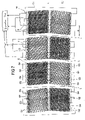
- FIG. 7 is a schematic representation of a measuring graduation of a rotary encoder having a defined grating constant, which is scanned by a scanning unit having a detection device.
- FIG. 7 schematically illustrates a section of a measuring graduation M of a rotary encoder (angular position-measuring system) which includes a plurality of graduation marks T having a grating constant d and arranged periodically one after the other along extension direction R (defined by a circular arc) of measuring graduation M.
- a rotary encoder angular position-measuring system
- a detector device D of a scanning unit which includes a plurality of detector elements E in the form of photo elements that are arranged one after the other in two side-by-side tracks S 1 , S 2 along extension direction R of measuring graduation M.
- Individual detector elements E in the form of photo elements are selected with respect to their size, their arrangement one after the other and their geometry such that, when scanning a measuring graduation of a rotary encoder having a grating constant smaller by fourfold than measuring graduation M illustrated in FIG. 7 , generate output signals which, because of the geometry of individual detector elements E, are free of specific, predefined harmonics.
- each individual detector element E generates an output signal having a specific phase
- detector elements E which are set apart from each other along extension direction R and generate output signals of the same phase supply their respective output signals as a unified signal to an evaluation unit where the output signals of different phases may be evaluated, thereby making it possible to determine the relative location of detection device D with respect to measuring graduation M along extension or measuring direction R.
- measuring graduation M on one hand and detection device D on the other hand are allocated to two different machine parts of a machine tool and are in each case joined to them, it is thereby possible to determine a relative movement of the two machine parts with respect to each other.
- detector elements E For scanning measuring graduation M, illustrated in FIG. 7 , whose grating constant d is greater than the grating constant of that measuring graduation for whose scanning, individual detector elements E as such are originally designed and arranged, detector elements E are combined to form detector groups G 1 , G 2 , G 3 , G 4 which are distributed on both tracks S 1 , S 2 and in each case appear there several times.
- detector groups G 1 , G 2 , G 3 , G 4 there are four different types of detector groups G 1 , G 2 , G 3 , G 4 , each type G 1 or G 2 or G 3 or G 4 generating output signals of a specific phase (0° or 90° or 180° or 270°).
- Detector elements E are interconnected to form detector groups G 1 , G 2 , G 3 , G 4 in the manner that the output signals of the detector elements (electrical output signals in the case of detector elements in the form of photo elements which optically scan measuring graduation M) of a detector group G 1 , G 2 , G 3 or G 4 are each supplied jointly to the allocated evaluation unit. Detector elements E of one detector group G 1 , G 2 , G 3 or G 4 are thus in each case electrically interconnected. Moreover, those detector groups (set apart from each other along extension direction R) which generate an output signal of one and the same phase are interconnected, so that the output signals of one phase are fed jointly to the evaluation unit.
- all those detector groups G 1 which generate output signals of a phase of 0° are electrically interconnected; all those detector groups G 2 which generate output signals of a phase of 90° are electrically interconnected; all those detector groups G 3 which generate output signals of a phase of 180° are electrically interconnected; and all those detector groups G 4 which generate output signals of a phase of 270° are electrically interconnected.
- the detector elements of one detector group are in each case illustrated in FIG. 7 in that they have the same shaded portion. The same holds true for those detector groups, set apart from each other along extension direction R, which generate output signals having a matching phase.
- Gaps L between adjacent detector groups illustrated in FIG. 7 each include those detector elements which were not used when forming detector groups. Alternatively, it is possible to provide no sensors at gaps L from the start for technical reasons.
- rules are indicated and analyzed according to which the individual detector elements are able to be interconnected to form detector groups to, on one hand, obtain, e.g., the greatest possible filling factor, that is, to use as many detector elements as possible when forming the detector groups, and on the other hand, to be able to filter defined harmonics out of the output signals using the detector device formed by the detector groups.
- ⁇ x mod g f ⁇ 0 that is to say, distance ⁇ x between two detector groups of the same phase, formed according to the generation rule above, is not an integral multiple of underlying finest raster g f of individual detector elements E. This means that distance ⁇ x between two detector groups of the same phase, calculated according to the generation rule for the distance filter, may not be represented by an integral multiple of the underlying finest raster g f .
- n 3
- Resulting for the real detector arrangement are therefore real distances of, on one hand, 19*g f and 18*g f , the first-named, larger distance occurring twice as frequently as the second-named smaller, and on the other hand, real distances of 13*g f and 14*g f , the first-named, smaller distance occurring twice as frequently as the second-named, larger distance.
- distance filtering two-mark filtering
- width filter single-slit filter
- detector blocks made up in each case of two grating periods (d), i.e., made up of 32 detector elements E, are used alternately for filtering the cosine signal and for filtering the sine signal.
- the blocks used for filtering the cosine signal contain those detector groups G 1 , G 3 which generate output signals having a phase of 0° and 180°, respectively.
- the detector blocks used for filtering the sine signal include detector groups G 2 , G 4 which generate output signals having a phase of 90° and 270°, respectively.
- detector groups G 1 or G 3 , and G 2 or G 4 are subject alternately to a distance filter and a width filter.
- the width of detector groups G 1 which generate output signals having a phase of 0° is in each case eight detector elements.
- the width of the two detector groups G 3 which generate output signals having a phase of 180° is once eleven detector elements and once five detector elements.
- those detector groups G 1 which generate output signals having a phase of 0°, given a constant width, are subject to a distance filter, and those detector groups G 3 which generate output signals having a phase of 180° are subject to a width filter.
- the third detector block which again includes detector groups G 1 , G 3 that generate output signals having a phase of 0° and 180°, respectively, the situation is reversed.
- Those detector groups G 3 which generate an output signal having a phase of 180° have a constant width of eight detector elements there, while the other detector groups G 1 have a width of ten and six detector elements, respectively.
- detector groups G 2 , G 4 that generate output signals having a phase of 90° and 270°, respectively.
- detector groups G 2 which generate output signals having a phase of 90° each have a constant width of eight detector elements, while the two other detector groups G 4 in one case have a width of ten detector elements, and in the other case have a width of six detector elements.
- detector groups G 4 which generate output signals having a phase of 270° have a constant width of eight detector elements
- the other detector groups G 2 in one case have a width of eleven detector elements, and in the other case have a width of five detector elements.
- the distance between the detector groups which are subject to a distance filter varies. In the detector blocks illustrated in FIG. 2 , it amounts partially to eighteen and partially to nineteen detector elements.
- the width filter which in one part of the detector blocks is, formed by the combination of detector groups having the width of eleven detector elements with detector groups having the width of five detector elements, and in other detector blocks, is formed by the combination of detector groups having the width of ten detector elements with detector groups having the width of six detector elements. This is carried out for the reasons, indicated above, of minimizing the composite error of the arrangement, in order to optimize the filtering action.
- the arrangement illustrated in FIG. 2 may provide an improved symmetry both with respect to the filtering of the cosine signal on one hand and the filtering of the sine signal on the other hand, and with respect to the use of the width filter on one hand and the distance filter on the other hand in the individual detector blocks. In particular, this may improve the insensitivity of the arrangement to soiling.
- detector groups G 1 , G 2 , G 3 and G 4 illustrated in FIG. 2 permit a homogeneous filtering both of the sine signal and of the cosine signal.
- this arrangement may have the disadvantage of the loss of the one-field character of the scanning, i.e., obtaining all four phases from one signal period.
- detection device D includes two tracks S 1 , S 2 arranged side by side and perpendicular to its extension direction R (measuring direction), detector blocks having detector groups G 1 , G 3 for filtering the cosine signal and detector blocks having detector groups G 2 , G 4 for filtering the sine signal being arranged in alternation in each of the two tracks.
- detector blocks arranged side by side transversely to extension direction R are used for filtering different signals.
- a detector block for filtering the sine signal is arranged in the other track S 2 , and vice versa.
- a base unit which is used for filtering both the cosine signal and the sine signal and to this end includes both width filters and distance filters, has an extension of merely 32 detector elements (corresponding to two grating constants d of the measuring graduation to be scanned) along extension direction R. Therefore, another aspect of the arrangement illustrated in FIG. 3 , having two tracks S 1 , S 2 arranged side by side, parallel to one another along extension direction R, is in the reduction of the scanning length.
- gaps L between adjacent detector elements E correspond to detector elements of the detector device that are not used when forming detector groups G 1 , G 2 , G 3 and G 4 .
- the corresponding, unused detector elements are not connected to the evaluation unit, thus in particular are not interconnected with the further detector elements for forming detector groups.
- they may also be gaps L that, for technical reasons, contain no detector elements in any case.
- the original, finest structure having the smallest raster g f may already be implemented in a plurality of tracks, in order to achieve an additional degree of freedom for the optimal distribution of the detector elements for the filtering of the coarser track having a larger raster (cf. German Published Patent Application No. 100 20 575).
- FIG. 4 illustrates a detection device D having two tracks S 1 , S 2 arranged side by side transversely to extension direction R (measuring direction). Each of the two tracks S 1 , S 2 extends along measuring direction R.
- First track S 1 is formed by detector groups G 1 , G 3 which generate output signals having a phase of 0° and 180°, respectively
- second track S 2 is formed by detector groups G 2 , G 4 which generate output signals having a phase of 90° and 270°, respectively.
- the (supplementary) generator or generating function, complementary thereto, of a filter function reads:
- FIG. 4 illustrates an ideal arrangement of detector groups G 1 , G 2 , G 3 , G 4 .
- the problem may also exist here that the detector groups formed from real detector elements do not have precisely the location and extension indicated by the generating filter functions. Accordingly, here as well, the composite error may be minimized or eliminated to the greatest extent possible by the suitable arrangement of detector groups, each of which has deviations from the ideal detector group. This is accomplished on the basis of the same principle explained above for errors f 1 and f 2 when filtering the harmonics by a distance filter and a width filter.
- the individual detector groups are characterized by a characteristic variation of their extension transversely to extension direction R.
- a filter function of the detection device designed for the scanning of the coarser measuring graduation may also be achieved by suitable interconnection of the individual detector elements along a direction Q transversely to the extension or measuring direction of detection device D. That is to say, specific to underlying measuring graduation M (cf. FIG. 7 ), detector elements are interconnected in the mark direction of graduation marks T of measuring graduation M. As already mentioned, this may only be possible if a sufficient number of detector elements are arranged side by side along transverse direction Q (perpendicular to extension direction R).
- the corresponding tracks may have detector elements from the start whose extension varies along transverse direction Q.
- the corresponding tracks may have detector elements from the start whose extension varies along transverse direction Q.
- only detector elements arranged side by side along extension direction R and having a different extension in transverse direction Q have to be interconnected in order to form the desired detector groups.
- detector regions that are arranged side by side in extension direction R and in each case have a different extension along transverse direction Q, are formed by detector elements which have a different extension along transverse direction Q from the start, or by the interconnection of smaller detector elements along transverse direction Q, these detector regions may in each case still be interconnected in extension direction R for forming detector groups.
- FIG. 5 a illustrates such an arrangement having two side-by-side tracks S 1 , S 2 , the one track S 1 having detector groups G 1 , G 3 which generate output signals having a phase: of 0° and 180°, respectively, and the other adjacent track S 2 containing detector groups G 2 , G 4 which generate output signals having a phase of 90° and 270°, respectively.
- h represents the height of the respective track S 1 , S 2 (extension transversely to extension direction R)
- N represents the number of detectors per graduation period d of the measuring graduation to be scanned
- k ⁇ N . . . N (that is, k assumes an integral value between ⁇ N and N).
- complementary filter functions each on the basis of a cosine function.
- FIG. 5 b schematically illustrates how an ideal filter function, represented by a solid line, on the basis of a sine or cosine function, may be reconstructed approximately by the interconnection of detector elements transversely to the extension direction of the detection device, and specifically for detector groups G 1 , G 3 of the phase 0° or 180° for example.
- the individual detector regions whose extension varies along a transverse direction Q perpendicular to extension direction R, may be achieved on one hand by the suitable interconnection of detector elements arranged side by side along transverse direction Q, or on the other hand in that the individual detector elements, which are ultimately interconnected along extension direction R to form detector groups G 1 , G 2 , G 3 , G 4 , have a different extension along transverse direction Q from the start.
- n represents the harmonic to be filtered
- m represents a whole number
- g f represents the grating constant of the periodic arrangement of the detector elements.
- d represents the grating constant of the measuring graduation to be scanned
- i represents a natural number.
- ⁇ x is generally not an integral multiple of g f , so that actual displacement distance ⁇ x of detector groups, which may really only be formed by an integral multiple of g f , deviates from the ideal value for ⁇ x here, as well.
- the composite error may again be minimized here, as explained above using the width filter and the distance filter as an example.
Landscapes
- Physics & Mathematics (AREA)
- General Physics & Mathematics (AREA)
- Optical Transform (AREA)
- Vehicle Body Suspensions (AREA)
- Body Structure For Vehicles (AREA)
- Analysing Materials By The Use Of Radiation (AREA)
- Length Measuring Devices With Unspecified Measuring Means (AREA)
- Transmission And Conversion Of Sensor Element Output (AREA)
Applications Claiming Priority (2)
| Application Number | Priority Date | Filing Date | Title |
|---|---|---|---|
| DE10338991.1 | 2003-08-18 | ||
| DE10338991A DE10338991A1 (de) | 2003-08-18 | 2003-08-18 | Positionsmesseinrichtung |
Publications (2)
| Publication Number | Publication Date |
|---|---|
| US20050051716A1 US20050051716A1 (en) | 2005-03-10 |
| US7084390B2 true US7084390B2 (en) | 2006-08-01 |
Family
ID=34129600
Family Applications (1)
| Application Number | Title | Priority Date | Filing Date |
|---|---|---|---|
| US10/921,452 Expired - Lifetime US7084390B2 (en) | 2003-08-18 | 2004-08-18 | Position-measuring device including measuring graduation and scanning unit |
Country Status (6)
| Country | Link |
|---|---|
| US (1) | US7084390B2 (https=) |
| EP (1) | EP1515123B1 (https=) |
| JP (1) | JP4746294B2 (https=) |
| CN (1) | CN100343624C (https=) |
| AT (1) | ATE456785T1 (https=) |
| DE (2) | DE10338991A1 (https=) |
Cited By (2)
| Publication number | Priority date | Publication date | Assignee | Title |
|---|---|---|---|---|
| US20070024865A1 (en) * | 2005-07-26 | 2007-02-01 | Mitchell Donald K | Optical encoder having slanted optical detector elements for harmonic suppression |
| US20120075622A1 (en) * | 2010-09-24 | 2012-03-29 | Canon Kabushiki Kaisha | Rotary encoder and optical apparatus |
Families Citing this family (5)
| Publication number | Priority date | Publication date | Assignee | Title |
|---|---|---|---|---|
| DE102010002902A1 (de) * | 2010-03-16 | 2011-09-22 | Dr. Johannes Heidenhain Gmbh | Abtasteinheit für eine optische Positionsmesseinrichtung |
| ES2701307T3 (es) * | 2016-06-07 | 2019-02-21 | Heidenhain Gmbh Dr Johannes | Medida materializada así como dispositivo de medición de posición |
| US10168189B1 (en) * | 2017-06-29 | 2019-01-01 | Mitutoyo Corporation | Contamination and defect resistant optical encoder configuration for providing displacement signal having a plurality of spatial phase detectors arranged in a spatial phase sequence along a direction transverse to the measuring axis |
| DE102018202556A1 (de) * | 2018-02-20 | 2019-08-22 | Dr. Johannes Heidenhain Gmbh | Optische Positionsmesseinrichtung |
| CN108444506B (zh) * | 2018-05-31 | 2024-03-22 | 苏州汇川技术有限公司 | 编码器码盘、绝对值编码器、位置获取方法及系统 |
Citations (19)
| Publication number | Priority date | Publication date | Assignee | Title |
|---|---|---|---|---|
| DE4411808A1 (de) | 1993-04-10 | 1994-10-13 | Heidenhain Gmbh Dr Johannes | Magnetisches Meßsystem |
| DE19505176A1 (de) | 1994-02-25 | 1995-08-31 | Baumer Electric Ag | Optischer Meßgeber |
| US5604345A (en) * | 1994-11-25 | 1997-02-18 | Mitutoyo Corporation | Optical encoder having a combination of a uniform grating and a non-uniform grating |
| US5814812A (en) * | 1995-09-01 | 1998-09-29 | Dr. Johannes Heidenhain Gmbh | Device for filtering of harmonic signal components |
| US5874729A (en) * | 1996-07-16 | 1999-02-23 | Johannes Heidenhain Gmbh | Device for filtering odd-numbered harmonic signal components |
| US5889280A (en) * | 1996-01-23 | 1999-03-30 | Mitutoyo Corporation | Apparatus for measuring displacement |
| DE19855685A1 (de) | 1997-12-03 | 1999-06-10 | Mitutoyo Corp | Induktive Positionsmeßeinrichtung |
| US5981942A (en) * | 1996-10-25 | 1999-11-09 | Okuma Corporation | Optical encoder for detecting relative displacement based on signals having predetermined phase differences |
| US5994692A (en) * | 1995-03-25 | 1999-11-30 | Dr. Johannes Heidenhain Gmbh | Photo-electric position measuring system having a scanning grating with transverse graduations |
| US6094307A (en) * | 1996-05-17 | 2000-07-25 | Okuma Corporation | Optical grating and encoder |
| US20010017349A1 (en) * | 1999-12-23 | 2001-08-30 | Wolfgang Holzapfel | Position measuring system |
| DE10020575A1 (de) | 2000-04-28 | 2001-10-31 | Heidenhain Gmbh Dr Johannes | Abtasteinheit für eine optische Positionsmesseinrichtung |
| DE10128619A1 (de) | 2000-06-14 | 2001-12-20 | Asahi Optical Co Ltd | Magnetischer Inkrementalcodierer und Vermessungsinstrument mit einem magnetischen Inkrementalcodierer |
| US20020008195A1 (en) * | 2000-07-03 | 2002-01-24 | Mitutoyo Corporation | Optical encoder and method of fabricating its sensor head |
| US6392224B1 (en) * | 1997-08-07 | 2002-05-21 | Dr. Johannes Heidenhain Gmbh | Scanning unit for an optical position measuring device |
| US6528783B1 (en) * | 1998-12-17 | 2003-03-04 | Bishop Innovation Limited | Position sensor and circuit for optical encoder |
| US20030048536A1 (en) * | 2001-09-13 | 2003-03-13 | Mitutoyo Corporation | Photoelectric encoder |
| US20030047673A1 (en) * | 2001-08-30 | 2003-03-13 | Microe Systems | Harmonic suppressing photodetector array |
| EP1308700A2 (en) | 2001-11-06 | 2003-05-07 | Dr. Johannes Heidenhain GmbH | Multiple resolution photodiode sensor array for an optical encoder |
Family Cites Families (14)
| Publication number | Priority date | Publication date | Assignee | Title |
|---|---|---|---|---|
| JPS629218A (ja) * | 1985-07-08 | 1987-01-17 | Hitachi Metals Ltd | 磁気式回転検出器 |
| DE3616144A1 (de) * | 1986-05-14 | 1987-11-19 | Heidenhain Gmbh Dr Johannes | Fotoelektrische messeinrichtung |
| JPH075954B2 (ja) * | 1987-12-10 | 1995-01-25 | 九築工業株式会社 | 転炉ライニング築造装置 |
| JPH02193003A (ja) * | 1989-01-23 | 1990-07-30 | Fujitsu Ltd | リニアパルスモータの位置センサ機構 |
| JPH03128418A (ja) * | 1989-07-20 | 1991-05-31 | Yokogawa Electric Corp | 光学式エンコーダ |
| JP2670193B2 (ja) * | 1991-02-25 | 1997-10-29 | オークマ株式会社 | 位置検出器 |
| EP0541827B1 (de) * | 1991-11-04 | 1995-04-12 | Dr. Johannes Heidenhain GmbH | Vorrichtung zur Erzeugung oberwellenfreier periodischer Signale |
| JPH0626885A (ja) * | 1992-07-07 | 1994-02-04 | Tamagawa Seiki Co Ltd | 光学式エンコーダにおけるエンコーダ信号の歪除去方法 |
| DE59306689D1 (de) * | 1993-08-07 | 1997-07-10 | Heidenhain Gmbh Dr Johannes | Vorrichtung zur Erzeugung oberwellenfreier periodischer Signale |
| JP3327718B2 (ja) * | 1995-01-23 | 2002-09-24 | オークマ株式会社 | 光学式エンコーダ |
| DE19508700C1 (de) * | 1995-03-02 | 1996-08-14 | Huebner Elektromasch Ag | Vorrichtung zum Gewinnen weitgehend oberwellenfreier periodischer Signale |
| JP3215289B2 (ja) * | 1995-04-17 | 2001-10-02 | オークマ株式会社 | スケール及びエンコーダ |
| DE59508231D1 (de) * | 1995-06-22 | 2000-05-31 | Heidenhain Gmbh Dr Johannes | Positionsmesseinrichtung |
| JP3209914B2 (ja) * | 1996-03-19 | 2001-09-17 | オークマ株式会社 | 光学式エンコーダ |
-
2003
- 2003-08-18 DE DE10338991A patent/DE10338991A1/de not_active Withdrawn
-
2004
- 2004-07-22 DE DE502004010699T patent/DE502004010699D1/de not_active Expired - Lifetime
- 2004-07-22 EP EP04017269A patent/EP1515123B1/de not_active Expired - Lifetime
- 2004-07-22 AT AT04017269T patent/ATE456785T1/de not_active IP Right Cessation
- 2004-08-18 CN CNB200410056762XA patent/CN100343624C/zh not_active Expired - Fee Related
- 2004-08-18 US US10/921,452 patent/US7084390B2/en not_active Expired - Lifetime
- 2004-08-18 JP JP2004238243A patent/JP4746294B2/ja not_active Expired - Fee Related
Patent Citations (25)
| Publication number | Priority date | Publication date | Assignee | Title |
|---|---|---|---|---|
| DE4411808A1 (de) | 1993-04-10 | 1994-10-13 | Heidenhain Gmbh Dr Johannes | Magnetisches Meßsystem |
| US5619132A (en) | 1993-04-10 | 1997-04-08 | Johannes Heidenhain Gmbh | Position measuring device employing primary and auxiliary magnetic fields |
| DE19505176A1 (de) | 1994-02-25 | 1995-08-31 | Baumer Electric Ag | Optischer Meßgeber |
| US5604345A (en) * | 1994-11-25 | 1997-02-18 | Mitutoyo Corporation | Optical encoder having a combination of a uniform grating and a non-uniform grating |
| US5994692A (en) * | 1995-03-25 | 1999-11-30 | Dr. Johannes Heidenhain Gmbh | Photo-electric position measuring system having a scanning grating with transverse graduations |
| US5814812A (en) * | 1995-09-01 | 1998-09-29 | Dr. Johannes Heidenhain Gmbh | Device for filtering of harmonic signal components |
| US5889280A (en) * | 1996-01-23 | 1999-03-30 | Mitutoyo Corporation | Apparatus for measuring displacement |
| US6094307A (en) * | 1996-05-17 | 2000-07-25 | Okuma Corporation | Optical grating and encoder |
| US5874729A (en) * | 1996-07-16 | 1999-02-23 | Johannes Heidenhain Gmbh | Device for filtering odd-numbered harmonic signal components |
| US5981942A (en) * | 1996-10-25 | 1999-11-09 | Okuma Corporation | Optical encoder for detecting relative displacement based on signals having predetermined phase differences |
| US6392224B1 (en) * | 1997-08-07 | 2002-05-21 | Dr. Johannes Heidenhain Gmbh | Scanning unit for an optical position measuring device |
| DE19855685A1 (de) | 1997-12-03 | 1999-06-10 | Mitutoyo Corp | Induktive Positionsmeßeinrichtung |
| US6259249B1 (en) | 1997-12-03 | 2001-07-10 | Mitutoyo Corporation | Induction-type position measuring apparatus |
| US6528783B1 (en) * | 1998-12-17 | 2003-03-04 | Bishop Innovation Limited | Position sensor and circuit for optical encoder |
| US20010017349A1 (en) * | 1999-12-23 | 2001-08-30 | Wolfgang Holzapfel | Position measuring system |
| DE10020575A1 (de) | 2000-04-28 | 2001-10-31 | Heidenhain Gmbh Dr Johannes | Abtasteinheit für eine optische Positionsmesseinrichtung |
| US20040046113A1 (en) | 2000-04-28 | 2004-03-11 | Mayer Elmar J. | Scanning unit for an optical position measuring device |
| US20020005716A1 (en) | 2000-06-14 | 2002-01-17 | Asahi Kogaku Kogyo Kabushiki Kaisha | Magnetic encoder and survey instrument having magnetic encoder |
| DE10128619A1 (de) | 2000-06-14 | 2001-12-20 | Asahi Optical Co Ltd | Magnetischer Inkrementalcodierer und Vermessungsinstrument mit einem magnetischen Inkrementalcodierer |
| US6492806B2 (en) | 2000-06-14 | 2002-12-10 | Pentax Corporation | Magnetic encoder and survey instrument having magnetic encoder |
| US20020008195A1 (en) * | 2000-07-03 | 2002-01-24 | Mitutoyo Corporation | Optical encoder and method of fabricating its sensor head |
| US20030047673A1 (en) * | 2001-08-30 | 2003-03-13 | Microe Systems | Harmonic suppressing photodetector array |
| US20030048536A1 (en) * | 2001-09-13 | 2003-03-13 | Mitutoyo Corporation | Photoelectric encoder |
| EP1308700A2 (en) | 2001-11-06 | 2003-05-07 | Dr. Johannes Heidenhain GmbH | Multiple resolution photodiode sensor array for an optical encoder |
| US20030085345A1 (en) | 2001-11-06 | 2003-05-08 | Franklin Ruth E. | Multiple resolution photodiode sensor array for an optical encoder |
Cited By (8)
| Publication number | Priority date | Publication date | Assignee | Title |
|---|---|---|---|---|
| US20070024865A1 (en) * | 2005-07-26 | 2007-02-01 | Mitchell Donald K | Optical encoder having slanted optical detector elements for harmonic suppression |
| WO2007016051A3 (en) * | 2005-07-26 | 2007-05-03 | Gsi Group Corp | Optical encoder having slanted optical detector elements for harmonic suppression |
| US20070153292A1 (en) * | 2005-07-26 | 2007-07-05 | Gsi Group Corporation | Optical encoder having slanted optical detector elements for harmonic suppression |
| US7324212B2 (en) * | 2005-07-26 | 2008-01-29 | Gsi Group Corporation | Optical encoder having slanted optical detector elements for harmonic suppression |
| GB2444187A (en) * | 2005-07-26 | 2008-05-28 | Gsi Group Corp | Optical encoder having slanted optical detector elements for harmonic suppression |
| GB2444187B (en) * | 2005-07-26 | 2009-11-18 | Gsi Group Corp | Optical encoder having slanted optical detector elements for harmonic suppression |
| US20120075622A1 (en) * | 2010-09-24 | 2012-03-29 | Canon Kabushiki Kaisha | Rotary encoder and optical apparatus |
| US8546747B2 (en) * | 2010-09-24 | 2013-10-01 | Canon Kabushiki Kaisha | Rotary encoder and optical apparatus |
Also Published As
| Publication number | Publication date |
|---|---|
| EP1515123A1 (de) | 2005-03-16 |
| US20050051716A1 (en) | 2005-03-10 |
| JP2005062194A (ja) | 2005-03-10 |
| ATE456785T1 (de) | 2010-02-15 |
| EP1515123B1 (de) | 2010-01-27 |
| CN1584492A (zh) | 2005-02-23 |
| DE502004010699D1 (de) | 2010-03-18 |
| CN100343624C (zh) | 2007-10-17 |
| JP4746294B2 (ja) | 2011-08-10 |
| DE10338991A1 (de) | 2005-03-17 |
Similar Documents
| Publication | Publication Date | Title |
|---|---|---|
| US6392224B1 (en) | Scanning unit for an optical position measuring device | |
| US6452159B2 (en) | Position measuring system | |
| US6742275B2 (en) | Scale and position measuring system for absolute position determination | |
| US7324212B2 (en) | Optical encoder having slanted optical detector elements for harmonic suppression | |
| US6747262B2 (en) | Position measuring system | |
| US7084390B2 (en) | Position-measuring device including measuring graduation and scanning unit | |
| EP1995566B1 (de) | Maßstab für eine Positionsmesseinrichtung und Positionsmesseinrichtung | |
| US20060180748A1 (en) | Position measuring instrument | |
| US20190003858A1 (en) | Contamination and defect resistant optical encoder configuration for providing displacement signals | |
| US7112782B2 (en) | Optical position measuring system | |
| JP3278361B2 (ja) | 光学式エンコーダ | |
| US8493569B2 (en) | Optical encoder readhead configuration with phosphor layer | |
| JP3215289B2 (ja) | スケール及びエンコーダ | |
| DE102018210749A1 (de) | Verschmutzungs- und defektbeständige optische Codiererkonfiguration zum Bereitstellen von Verschiebungssignalen | |
| JP3245610B2 (ja) | 奇数次の高調波信号成分を濾波する装置 | |
| JP2888482B2 (ja) | 高調波信号成分を濾波する装置 | |
| DE69523996T2 (de) | Detektorreihe für interferometrische Messsysteme | |
| US10295648B2 (en) | Contamination and defect resistant optical encoder configuration including a normal of readhead plane at a non-zero pitch angle relative to measuring axis for providing displacement signals | |
| US20190033100A1 (en) | Contamination and defect resistant rotary optical encoder configuration for providing displacement signals | |
| US7404259B2 (en) | Optical position measuring instrument | |
| US6094307A (en) | Optical grating and encoder | |
| JP3184419B2 (ja) | 光学格子およびエンコーダ | |
| DE102018210745A1 (de) | Verschmutzungs- und defektbeständige optische Codiererkonfiguration zum Bereitstellen von Verschiebungssignalen | |
| DE102018251727A1 (de) | Verschmutzungs- und defektbeständige optische Drehpositionsgeberkonfiguration zum Bereitstellen von Verschiebungssignalen | |
| DE9116805U1 (de) | Interferentielle Meßeinrichtung für wenigstens eine Meßrichtung |
Legal Events
| Date | Code | Title | Description |
|---|---|---|---|
| AS | Assignment |
Owner name: DR. JOHANNES HEIDENHAIN GMBH, GERMANY Free format text: ASSIGNMENT OF ASSIGNORS INTEREST;ASSIGNOR:MAYR, ELMAR;REEL/FRAME:015736/0841 Effective date: 20040806 |
|
| STCF | Information on status: patent grant |
Free format text: PATENTED CASE |
|
| FPAY | Fee payment |
Year of fee payment: 4 |
|
| FPAY | Fee payment |
Year of fee payment: 8 |
|
| MAFP | Maintenance fee payment |
Free format text: PAYMENT OF MAINTENANCE FEE, 12TH YEAR, LARGE ENTITY (ORIGINAL EVENT CODE: M1553) Year of fee payment: 12 |