US7010952B2 - Device for holding at least one roller of a rolling machine - Google Patents
Device for holding at least one roller of a rolling machine Download PDFInfo
- Publication number
- US7010952B2 US7010952B2 US10/811,631 US81163104A US7010952B2 US 7010952 B2 US7010952 B2 US 7010952B2 US 81163104 A US81163104 A US 81163104A US 7010952 B2 US7010952 B2 US 7010952B2
- Authority
- US
- United States
- Prior art keywords
- coupling
- roller
- groove
- recited
- arrangements
- Prior art date
- Legal status (The legal status is an assumption and is not a legal conclusion. Google has not performed a legal analysis and makes no representation as to the accuracy of the status listed.)
- Expired - Fee Related, expires
Links
Images


Classifications
-
- B—PERFORMING OPERATIONS; TRANSPORTING
- B21—MECHANICAL METAL-WORKING WITHOUT ESSENTIALLY REMOVING MATERIAL; PUNCHING METAL
- B21B—ROLLING OF METAL
- B21B31/00—Rolling stand structures; Mounting, adjusting, or interchanging rolls, roll mountings, or stand frames
- B21B31/08—Interchanging rolls, roll mountings, or stand frames, e.g. using C-hooks; Replacing roll chocks on roll shafts
-
- B—PERFORMING OPERATIONS; TRANSPORTING
- B21—MECHANICAL METAL-WORKING WITHOUT ESSENTIALLY REMOVING MATERIAL; PUNCHING METAL
- B21B—ROLLING OF METAL
- B21B31/00—Rolling stand structures; Mounting, adjusting, or interchanging rolls, roll mountings, or stand frames
- B21B31/02—Rolling stand frames or housings; Roll mountings ; Roll chocks
-
- B—PERFORMING OPERATIONS; TRANSPORTING
- B21—MECHANICAL METAL-WORKING WITHOUT ESSENTIALLY REMOVING MATERIAL; PUNCHING METAL
- B21B—ROLLING OF METAL
- B21B31/00—Rolling stand structures; Mounting, adjusting, or interchanging rolls, roll mountings, or stand frames
- B21B31/07—Adaptation of roll neck bearings
Definitions
- the invention relates to a device for holding at least one roller of a rolling machine and a rolling machine.
- Rolling methods that involve compressive forming are among many methods that are used in forming work pieces from an initial shape into a desired intermediate shape (semi-finished product, pre-forming) or final shape (end product, final forming).
- the work piece rolling stock
- the roll forming method work piece sections are arranged on the periphery of the rollers, which enable the generation of corresponding profiles in the work piece.
- the cylindrical or conical outer surfaces of the rollers act directly on the work piece.
- rolling methods are divided into “longitudinal rolling”, “transverse rolling” and “cross rolling”.
- longitudinal rolling the work piece is moved through a gap between the rollers (roller gap) that is perpendicular to the rotational axes of the rollers in a translational motion, most often without rotating.
- transverse rolling the work piece does not move in a translational motion, relative to the rollers or their rotational axes, but rather turns only around its own axis.
- rollers are here generally slanted relative to each other such that the work piece is moved translationally and rotationally.
- Grooved cross rolling machines typically include two rollers with wedge-shaped profiled tools, and are arranged on the rolling machines' outer periphery.
- the two rollers rotate in the same direction about parallel rotational axes, and are sometimes also referred to as “cross wedge rollers”.
- the profiled tools have a wedge-shaped or triangular (at the cross-section) geometry as their axial dimensions along the periphery either increase in one direction and/or run slanted to the rotational axis of the rollers.
- cross wedge rollers or grooved cross rollers, enable a versatile forming of work pieces within high precision, and dimensional accuracy.
- the wedge-shaped tools can produce continuous grooves and other tapers in the rotating work piece.
- Increasing or decreasing the outer diameter of the tool wedge while proceeding around the rotational axis makes it possible, in combination with the slanted arrangement, to generate axially-running slants and continuous transitions between two tapers of varying diameter in the work piece.
- Cross wedge rollers are particularly suited for manufacturing elongated, rotationally symmetrical work pieces with constrictions or elevations, such as with cams or ribs.
- German Patent Application No. DE 1 477 088 C describes a cross wedge rolling machine for transversely rolling rotational solids or flat work pieces with two working rollers rotating in the same rotational direction, whose rolling surfaces accommodate exchangeable wedge tools.
- the wedge tools each have wedge-shaped (or triangular) reduction strips that ascend from the roller jacket to an end height tailored to the work piece to be manufactured, and are roughened such as by knurling, along with wedge-shaped, smooth forming surfaces with a calibration effect spaced identically apart from the roller jacket.
- the wedge tools are designed as deformation segments, and only traverse a partial area of the accompanying roller surface. The facing surfaces and tools of the two working rollers move or rotate in an opposite direction relative to each other on the work piece.
- German Patent Application No. DE 39 26 356 C2 describes a rolling machine with exchangeable working rollers.
- Each of the working rollers is provided on one face with a cylindrical tap mounted on a divided clamping element of a drive shaft, wherein a movable clamping part of the clamping element is connected with a fixed clamping part at least by one screw and one nut.
- the opposing face of each working roller exhibits a cylindrical tap mounted on a divided clamping element of the thrust cylinder, whose moveable clamping part is again connected with a fixed clamping part by means of at least one screw and one nut.
- the working shaft is made to rotate by a drive via the drive shaft.
- the accompanying clamping element and mounted cylindrical tap impart the active torque from the drive shaft to the roller.
- German Patent Application No. DE 309 408 C discloses the mount for a typewriter plate.
- German Patent Application No. DE 891 642 C discloses a roller mounting plate for a rolling machine.
- each bearing journal has a coupling flange on the roller stand into which a centering shoulder of the roller body can be inserted without one or both bearing journals axially shifting.
- the coupling flange can be designed as a pocket, in which the centering shoulder of the roller body is inserted and held in place by an end cap. Bolts or screws can be provided for securing the centering shoulder and coupling flanges to each other.
- an advantage in the art can be realized with systems and methods that provide a simple and reliable mount for the roller of a rolling machine, and that provide a corresponding rolling machine for implementing the same.
- Implementations of the present invention provide a simple and reliable mount for a roller of a rolling machine.
- the device according to claim 1 is suited and intended for holding at least one roller of a rolling machine that canes rotate around a rotational axis, and encompasses two holding arrangements that can be arranged on opposing faces of the roller, (when viewed in the direction of the rotational axis), and at least two holding arrangements that have both a coupled mode (e.g., a power or torque-transmitting mode) for the torque-transmitting linkage of each holding arrangement with the roller and an uncoupled mode (e.g., no-power or torque mode).
- a coupled mode e.g., a power or torque-transmitting mode
- an uncoupled mode e.g., no-power or torque mode
- the holding arrangements have at least two paired couplings each comprising at least a first groove as well as at least one corresponding first coupling element on the one hand, and at least one second groove not running parallel to the first groove as well as at least one corresponding second coupling element on the other.
- the first and second groove(s) are formed on a first coupling part, and the first and second coupling elements are formed on a second coupling part of the respective coupling arrangement.
- the roller mount between the holding arrangements is detachable in design. To this end, the roller can be removed from the holding arrangements with the holding arrangements uncoupled.
- the rolling machine according to the invention encompasses at least two rollers that can rotate around a respective rotational axis, and in particular can be equipped with tools: at least one rotational drive for rotating the rollers, when forming a work piece that is arranged between the rollers, and a device according for holding the rollers.
- forming refers to changing the shape of a work piece into another shape in any way, and including “pre-forming” and “final forming”.
- the rotational axes of the rollers are to be viewed as geometrical or mathematical axes in a Euclidean, three-dimensional space, around which the rollers turn.
- power-transmitting or mechanical axes are referred to as “shafts” in this application.
- the first grooves, and preferably the second grooves as well are each formed on a groove base.
- the first groove is embedded more deeply than the second groove in each first coupling part of the holding arrangements (alternatively, the groove base is arranged further down), so that the first coupling element does not hit the groove base of the first base when the second coupling element positively engages the second groove.
- the coupling elements generally do not abut the groove base of the accompanying grooves when the holding arrangements are coupled, thereby avoiding a geometric correlation.
- the first grooves and second grooves of the holding arrangements can be downwardly and partially open (i.e., slit-like in design).
- the first coupling element of the accompanying second coupling part also positively engages the first groove of the accompanying first coupling part with each of the holding arrangements coupled to additionally stabilize the connection.
- the first groove and second groove of the first coupling part of each coupling arrangement are preferably arranged orthogonally relative to each other. This enables an optimal power transmission and mounting in the coupled mode.
- the first grooves of the first coupling parts and preferably the second grooves of the first coupling parts are generally continuous in design.
- the second coupling part can encompass at least two respectively separated first coupling elements and two separated second coupling elements, which preferably are arranged on various sides of the rotational axis, and then in particular are separated from each other by a central area around the rotational axis.
- the first and second grooves of the first coupling parts, as well as the first and second coupling elements of the second coupling parts each preferably run radially to the rotational axis when the respective coupling arrangement is coupled.
- the side walls of the second grooves and the second coupling elements, and also of the first grooves and first coupling elements, to be positively interlocked, are essentially perpendicular and/or flat in design in order to form a good opposite surface of force for the positive fit.
- the first grooves are preferably used as guide grooves when assembling or disassembling the rollers.
- the first grooves are essentially straight or linear in design.
- the first grooves of the first coupling parts are outwardly open at their ends, in order to introduce the first coupling elements along the groove.
- the first grooves can outwardly expand at least at one of their open ends and form guide surfaces for the first coupling element to be introduced.
- the first coupling element can also be tapered at one of its corresponding free ends that correspond or slide thereupon to interface with the guide surfaces of the first groove.
- the first grooves of the first coupling parts of the two holding arrangements are preferably oriented or adjustable essentially parallel to each other.
- At least one positioning arrangement is provided for positioning at least one of the two holding arrangements axially to the rotational axis of the roller, moving them toward each other and away from each other.
- the roller can be mounted between the two holding arrangements by moving the roller into a position between the two holding arrangements parallel to the first grooves in a first step with the holding arrangements uncoupled while guiding the first coupling elements in the first grooves of the first coupling parts of both holding arrangements, after which the accompanying holding arrangements are switched to the coupled mode in a second step by feeding at least one of the two holding arrangements to the roller. The roller is then reliably held between the holding arrangements.
- the roller is disassembled from the holding arrangements by initially moving the two holding arrangements from their coupled mode to their uncoupled mode by moving at least one of the two holding arrangements away from the roller, after which the roller is moved into a position outside the two holding arrangements while guiding the first coupling elements in a removal direction, or a direction running parallel to the first grove.
- Stop surfaces which abut each other when the holding arrangements are in couple mode, are arranged or secured on the holding arrangements.
- the rollers' front sides face each other in order to limit the feeding motion, and to fix the roller in place between the holding arrangements.
- positioning means are provided for positioning the roller relative to the holding arrangements in a position where the two holding arrangements can be switched from the uncoupled to coupled mode and vice versa.
- These positioning means are preferably formed with corresponding stop means, which retain or stop the rollers in the direction of introduction. In particular, this position makes it possible to feed the holding arrangements to the roller, for switching the coupling arrangement to its coupled mode, and/or to introduce the second coupling element of the accompanying second coupling part into the second groove of the accompanying first coupling part.
- the positioning means can encompass positioning elements that intermesh from the back.
- the positioning means are generally designed in such a way as to enable or not impede the feeding motion of the holding arrangements relative to the roller.
- the device further includes apparatus configured for holding at least two rollers of a rolling machine that can rotate around a rotational axis, and then encompasses a respective two holding arrangements and a respective two holding arrangements for each of the rollers.
- the holding arrangements and rollers can be arranged next to each other when assembled, or arranged one over the other viewed in the direction of gravitational force.
- At least two rollers can preferably be mounted sequentially in the same direction of introduction or from the same side of the rolling machine and/or the first roller to be mounted can be guided between the holding arrangements of the rollers to be subsequently mounted.
- the positioning means are now preferably designed and arranged on the rollers and holding arrangements in such a way that the roller to be mounted first can be guided between the holding arrangements of the rollers to be subsequently mounted, and is or can be positioned only in its desired location between the accompanying holding arrangements of this roller.
- the positioning means or stop means are for this purpose arranged at the end of the holding arrangement viewed in the direction of introduction, and at the front side of the roller on their faces or sides viewed in the direction of introduction, and the positioning means or stop means of a second roller to be mounted after the first roller are arranged at the beginning of the holding arrangement viewed in the direction of introduction, and on the faces or sides of the roller on the back side viewed in the direction of introduction.
- a special embodiment now makes it possible to incorporate at least two rollers between the accompanying holding devices in an unmistakable or clearly allocated fashion, in particular via the configuration of the accompanying holding arrangements and/or the accompanying positioning means.
- the rolling machine generally encompasses bearing arrangements for each holding arrangement, in which the holding arrangements are rotationally supported.
- the rotational axes of the rollers mounted in the holding arrangements are generally oriented essentially parallel to each other and/or essentially arranged over each other viewed in the direction of gravitational force and/or essentially perpendicular to the direction of gravitational force.
- the rolling machine is designed as a grooved cross-rolling machine or cross wedge rolling machine, whose basic structural design was described at the outset.
- the rollers exhibit profiled or wedge-shaped tools, and rotate in the same direction toward each other, wherein the work piece only rotates around its own axis, and is not translationally transported by the rollers, as opposed to longitudinal rollers.
- the tools on the rollers are wedge-shaped or triangular, in particular in terms of their cross section, and increase in radial dimensions in one direction along the periphery and/or run slanted relative to the rotational axis of the accompanying roller.
- FIG. 1 is a device for holding two rollers of a rolling machine situated one over the other, longitudinal section;
- FIG. 2 is a front view of the face of a holding arrangement for the upper roller according to FIG. 1 , including a coupling part with coupling elements;
- FIG. 3 is a front view of the face of the upper roller according to FIG. 1 , including a coupling part with coupling grooves;
- FIG. 4 is a front view of the face of a holding arrangement for the lower roller according to FIG. 1 , including a coupling part with coupling elements;
- FIG. 5 is a front view of the face of the lower roller according to FIG. 1 , including a coupling part with coupling grooves;
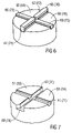
- FIG. 6 is a three-dimensional view of a second coupling part with four radial coupling elements
- FIG. 7 is a three-dimensional view of a first coupling part corresponding to the second coupling part according to FIG. 6 , with two radial coupling grooves;
- FIG. 8 is a three-dimensional view of the first coupling part according to FIG. 7 and the second coupling part according to FIG. 6 just prior to radial introduction;
- FIG. 9 is a three-dimensional view of the first coupling part according to FIG. 7 and the second coupling part according to FIG. 6 after introduced and just prior to coupling;
- FIG. 10 is a three-dimensional view of the first coupling part according to FIG. 7 and the second coupling part according to FIG. 6 after coupling;
- FIG. 11 is a three-dimensional view, rotated by 180° relative to the view in FIG. 10 , of the first coupling part according to FIG. 7 and the second coupling part according to FIG. 6 after coupling.
- FIGS. 1 to 11 Identical parts and dimensions in FIGS. 1 to 11 are denoted with the same reference symbols.
- FIG. 1 illustrates holding two working rollers 2 and 3 , and part of a rolling machine.
- FIG. 1 illustrates a cross wedge roller, or cross wedge rolling machine.
- the first working roller 2 rotates around a rotational axis A
- the second working roller 3 rotates around a rotational axis B.
- the rotational axes A and B are essentially arranged parallel to each other or perpendicular to the direction of the forces of gravity (or earth's attraction) denoted with the arrow, so that both working rollers 2 and 3 are arranged one right over the other.
- the working rollers exhibit an essentially cylindrical outer surface.
- Segmented or fully continuous tools each having a wedge-shaped cross section (not shown) are generally secured, in particular braced or bolted, to the outer surface or jacket surface of the working rollers 2 and 3 , and each are slanted and arranged at an angle relative to the respective rotational axis A and B and axially arranged relative to the rotational axes A and B in essentially the same positions.
- the tools advantageously also increase in cross section, wherein the increase in cross section proceeds in a direction opposite to the tools of different working rollers 2 and 3 .
- the left face 20 of the first, upper working roller 2 in FIG. 1 is provided with a flange-like first coupling part 6 A of a coupling arrangement 6
- the other, right face 21 is provided with a flange-like first coupling part 7 A of a coupling arrangement 7
- the left face 30 of the second, lower working roller 3 in FIG. 1 is also provided with a flange-like first coupling part 8 A of a coupling arrangement 8
- the other, right side 31 is provided with a flange-like first coupling part 9 A of a coupling arrangement 9 .
- the holding arrangements 6 to 9 each encompass respectively corresponding, also flange-like second coupling parts 6 B, 7 B, 8 B and 9 B, which are arranged or formed on a respective accompanying holding arrangement 12 , 13 , 14 and 15 designed as a rotating shaft.
- the holding arrangements 12 and 13 for the upper working roller 2 are rotationally supported in accompanying bearing arrangements 16 and 17 around rotational axis A by means of roller bearings (not designated in any greater detail).
- the holding arrangements 14 and 15 for the lower working roller 3 are rotationally supported in accompanying bearing arrangements 18 and 19 around rotational axis B by means of roller bearings (not designated in any greater detail).
- the holding arrangement 12 of the first working roller 2 and the holding arrangement 14 of the second working roller 3 each exhibit a shaft extension as a drive shaft 42 or 43 , which can each be connected or coupled with one or a shared rotational drive (not shown).
- the holding arrangements 6 to 9 are coupled in FIG. 1 , i.e., their coupling parts 6 A and 6 B, 7 A and 7 B, 8 A and 8 B as well as 9 A and 9 B intermesh.
- the upper first working roller 2 and the lower second working roller 3 are clamped or held between the accompanying holding arrangements 12 and 13 or 14 and 15 axially to their respective rotational axis A or B on the one hand, and torques or rotations of the holding arrangements 12 and 14 are conveyed synchronously via drive shafts 42 and 43 to the working rollers 2 and 3 and the opposing holding arrangements 13 and 15 on the other.
- Each of the working rollers 2 and 3 can now be removed from the holding arrangements 12 and 13 or 14 and 15 by uncoupling the accompanying holding arrangements 6 and 7 or 8 and 9 , and taken out of the arrangement for purposes of replacing the tools or all working rollers 2 and 3 .
- FIG. 2 and FIG. 6 show the second coupling part 6 B or 7 B
- FIG. 3 and FIG. 7 show the first coupling part 6 A or 7 A of the coupling arrangement 6 or 7 for the upper working roller 2
- FIG. 4 shows the second coupling part 8 B
- FIG. 5 shows the first coupling part 8 A of the coupling arrangement 8 for the lower working roller 3
- FIG. 8 and 11 further illustrate the two coupling parts 6 A and 6 B in varying positions.
- Both coupling parts 6 A and 6 B have the basic shape of a cylinder, with rotational axis A as the cylindrical axis.
- Coupling arrangement 7 is structurally identical to coupling arrangement 6
- coupling arrangement 9 is structurally identical to coupling arrangement 8 , as highlighted by the corresponding reference numbers placed in parentheses.
- Two continuous grooves 60 / 80 and 61 / 81 intersecting in the area of rotational axis A or B and oriented orthogonally relative to each other and radially to the rotational axis A or B are provided in the first coupling part 6 a or 8 A, and exhibit at least primarily a rectangular cross section or straight, perpendicular side walls.
- the first groove 60 or 80 is deeper or displaced further inward than the second groove 61 or 81 .
- the second coupling part 6 B or 8 B exhibits four radially running coupling elements 62 , 63 , 64 and 65 (or 82 , 83 , 84 , and 85 ) protruding or projecting axially to the rotational axis, which are offset by 90° relative to each other, and separated from each other in the area of rotational axis A or B by a central intermediate space.
- the coupling elements 62 and 64 or 82 and 84 are provided and designed for engaging the first groove 60 or 80 of the first coupling part 6 A or 8 A, and the coupling elements 63 and 65 or 83 and 85 for engaging the second groove 61 or 81 .
- the coupling elements 62 and 64 or 82 and 84 are here higher or designed to project further than the coupling elements 63 and 65 or 83 and 85 .
- the first grooves, e.g., 60 and 80 , and the accompanying coupling elements, e.g., 62 and 64 or 82 and 84 , of all holding arrangements 6 to 9 are oriented vertically or parallel to the gravitational force G
- the second grooves, e.g., 61 and 81 , and the accompanying coupling elements, e.g., 63 and 65 and 83 and 85 are correspondingly oriented horizontal or perpendicular to the gravitational force G.
- the bearing arrangements 17 and 19 now each have two bearing parts 17 A and 17 B or 19 A and 19 B, which can each be moved or adjusted relative to each other between two set positions axially or parallel to the rotational axis A or B and fixed in the set positions.
- the setting arrangement can also encompass a drive for automatic feeding or removal.
- the upper edge of the second coupling part 6 B of the coupling arrangement 6 exhibits a cut-off area for the upper working roller 2 , in which the coupling element 62 protrudes upwardly and narrows, forming guide surfaces.
- the upper edge of the first coupling part 6 A has a loop-shaped receptacle for the positioning element 66 of the coupling element 62 , which forms an additional positioning element 67 and also sits on the cut-off area of the second coupling part 6 B if the cylindrical axes of the coupling parts 6 A and 6 B coincide on rotational axis A.
- the lower edge of the first coupling part 8 A of the coupling arrangement 8 for the lower working roller 3 exhibits a cut-off area with a hook-shaped extension as the positioning element 86 .
- the lower edge of the second coupling part 8 B also exhibits a hook-shaped extension as the positioning element 87 , wherein the two hook-shaped positioning elements 86 and 87 intermesh from the back and abut each other if the cylindrical axes of the two coupling parts 8 A and 8 B coincide on rotational axis B.
- the accompanying bearing parts 17 A or 19 A along with the accompanying holding arrangements 13 or 15 are first moved out to the outer set position as appropriate.
- the lower working roller 3 with its two first coupling parts 8 A and 9 A can be initially guided from above between the sufficiently spaced two upper holding arrangements 12 and 13 and the coupling parts 6 B and 7 B.
- the design of the positioning elements 87 and 97 on the one hand, and of the positioning elements 66 and 76 on the other, ensures that the lower working roller 3 can pass the upper holding arrangements 12 and 13 .
- the working roller 3 with the first grooves 80 and 90 is subsequently threaded in the vertical insertion direction E (i.e., oriented parallel to the gravitational force G) over or on the coupling elements 82 and 92 , as shown in FIG. 8 for coupling arrangement 6 .
- a narrowed section at the beginning of the coupling element 82 and 92 and an expanded section 89 or 99 at the lower entrance of the groove 80 or 90 serve as guides or stop faces or lacing aids.
- the grooves 80 and 90 are now guided onto the coupling elements 82 and 92 , and then on the coupling elements 84 and 94 of the second coupling parts 8 B and 9 B, until the positioning elements 87 and 97 of the working rollers 2 and 3 hit the accompanying positioning elements 86 and 96 of the lower holding arrangements 14 and 15 .
- the set positions of the holding arrangements 14 and 15 are here selected in such a way that the coupling elements 82 and 84 as well as 92 and 94 engage the respective guiding grooves 80 and 90 on either side, and are guided by longitudinally running side walls.
- the two coupling parts 8 A and 8 B as well as 9 A and 9 B are arranged concentrically to rotational axis B in the end position of the working roller 3 defined by the positioning elements 86 , 87 , 96 and 97 when hooked together.
- transversely running coupling elements 83 and 85 as well as 93 and 95 are now engaged in the transversely running second grooves 81 and 91 by axially feeding the holding arrangement 15 in forward direction Z coaxially to the rotational axis B (as shown in FIG. 9 for coupling arrangement 6 ).
- the shape of coupling elements 82 to 85 as well as 92 to 95 can be adjusted to the grooves 80 and 81 as well as 90 and 91 in such a way as to generate a positive fit at least on the longitudinally running side walls during this engagement.
- the mutually abutting flat sides or stop surfaces 52 and 53 or 56 and 57 of the coupling parts 8 B and 8 A or 9 B and 9 A limit this feeding movement before the coupling elements 82 to 85 as well as 92 to 95 hit the groove base of the respective grooves 80 and 81 as well as 90 and 91 .
- the two holding arrangements 8 and 9 are now coupled, and a stable, torque-transmitting connection is realized between the working roller 3 and holding arrangements 14 and 15 .
- the first grooves 80 and 90 also exhibit upper expansions 88 and 98 . This is advantageous when guiding the lower working roller 3 with its grooves 80 and 90 on the coupling elements 62 and 64 and 72 and 74 of the upper coupling parts 6 B and 7 B as it passes between the upper holding arrangements 12 and 13 , since this facilitates both upward and downward lacing. All grooves can also be contacted at the upper edge (see FIG. 7 ).
- the upper working roller is mounted in similar fashion in an initial step by lacing or fitting it from above with the first grooves 60 and 70 of its first coupling parts 6 A and 7 A on the coupling elements 62 or 72 in the direction of introduction E ( FIG. 8 ).
- the narrowing area of the coupling element 62 which is part of the positioning element 66 , and an outwardly enlarging expansion 68 at the beginning of the first groove 60 serve as lacing aids or guides.
- the grooves 60 and 70 are further guided on the coupling elements 62 and 72 and then on the coupling elements 64 and 74 up to the end position defined by the stop of the positioning elements 66 / 76 and 67 / 77 , in which axial feeding in the forward direction Z takes place for positively joining the two grooves 61 and 71 with the accompanying coupling elements 63 and 65 or 73 and 75 ( FIG. 9 ).
- FIGS. 10 and 11 show the coupling arrangement 6 coupled in this way.
- the frontal stop surfaces 50 of the second coupling part 6 B and frontal stop surfaces 51 of the first coupling part 6 A are situated one on top of the other, and the coupling elements 62 and 64 positively engage the groove 60 at a distance from the groove base, while coupling elements 63 and 65 engage the groove 61 .
- the steps mentioned for assembly are performed in reverse order to remove or disassemble the working rollers 2 and 3 in removal direction opposite the advancing direction Z and a withdrawal direction opposite the direction of introduction E.
- the faces of the working rollers 2 and 3 each are provided with upper assembly aids 22 and 23 or 32 and 33 , so that they can be held during assembly or disassembly.
- the described measures have hence been used to easily switch or replace the working rollers 2 and 3 or their tools, and also to reversibly (or irreversibly) incorporate the two working rollers 2 and 3 given the special design of the positioning means 66 , 67 , 76 , 77 , 86 , 87 and 96 , 97 .
- the coupling parts are preferably made out of steel.
- the coupling elements can in particular be secured as prefabricated parts in grooves in a second coupling part, e.g., as shown in FIG. 8 , or also be molded onto or out of the coupling part itself.
- the grooves in the first or second coupling part are preferably generated via material degradation, in particular milling.
Applications Claiming Priority (2)
| Application Number | Priority Date | Filing Date | Title |
|---|---|---|---|
| DE10317312.9 | 2003-04-14 | ||
| DE10317312A DE10317312A1 (de) | 2003-04-14 | 2003-04-14 | Vorrichtung zum Halten wenigstens einer Walze einer Walzmaschine |
Publications (2)
| Publication Number | Publication Date |
|---|---|
| US20040200251A1 US20040200251A1 (en) | 2004-10-14 |
| US7010952B2 true US7010952B2 (en) | 2006-03-14 |
Family
ID=32892357
Family Applications (1)
| Application Number | Title | Priority Date | Filing Date |
|---|---|---|---|
| US10/811,631 Expired - Fee Related US7010952B2 (en) | 2003-04-14 | 2004-03-29 | Device for holding at least one roller of a rolling machine |
Country Status (5)
| Country | Link |
|---|---|
| US (1) | US7010952B2 (zh) |
| EP (1) | EP1468754B1 (zh) |
| JP (1) | JP4156547B2 (zh) |
| CN (1) | CN100392261C (zh) |
| DE (2) | DE10317312A1 (zh) |
Cited By (4)
| Publication number | Priority date | Publication date | Assignee | Title |
|---|---|---|---|---|
| US20070119223A1 (en) * | 2005-11-25 | 2007-05-31 | Langenstein And Schemann Gmbh | Apparatus For Holding At Least Two Rolls Of A Rolling Machine, And Rolling Machine |
| US9334890B2 (en) | 2012-01-24 | 2016-05-10 | Kennametal India Limited | Hardmetal roll clamping system onto the shaft and the method thereof |
| US20160130092A1 (en) * | 2013-05-31 | 2016-05-12 | Morné Rudolph | Segmented idler for use in a conveyor belt installation |
| US9975159B2 (en) | 2014-02-11 | 2018-05-22 | Sms Group Gmbh | Tool changeover system and method as well as roll |
Families Citing this family (5)
| Publication number | Priority date | Publication date | Assignee | Title |
|---|---|---|---|---|
| DE102008027968A1 (de) | 2008-06-12 | 2009-12-17 | Langenstein & Schemann Gmbh | Walzmaschine und Verfahren zum Wechseln der Walzen oder der Walzenwerkzeuge der Walzmaschine |
| CN100553815C (zh) * | 2008-09-11 | 2009-10-28 | 长治钢铁(集团)锻压机械制造有限公司 | 下辊快装机构 |
| DE102010060658B4 (de) | 2010-11-18 | 2014-11-20 | Langenstein & Schemann Gmbh | Walzmaschine zum Umformen von metallischen und/oder eisenhaltigen Werkstücken mit geklemmten Drehlagern und Verfahren zum Wechseln der Walzen oder der Walzenwerkzeuge der Walzmschine |
| CN102553927B (zh) * | 2012-01-09 | 2014-11-05 | 宁波大学 | 一种可更换辊系的铁道车轴辊式楔横轧机 |
| CN103071681A (zh) * | 2013-01-21 | 2013-05-01 | 天津惠利通钢管有限公司 | 用于焊管机组的传动轴快速换辊装置 |
Citations (7)
| Publication number | Priority date | Publication date | Assignee | Title |
|---|---|---|---|---|
| US2332859A (en) * | 1938-08-30 | 1943-10-26 | Kreissig Ernst | Shaft coupling |
| US2430683A (en) * | 1945-10-30 | 1947-11-11 | Morgan Construction Co | Wabbler coupling |
| US4866969A (en) * | 1985-09-06 | 1989-09-19 | Sms Schloemann-Siemag Aktiengesellschaft | Three-part roll assembly with exchangeable center part |
| US5450740A (en) * | 1994-02-25 | 1995-09-19 | Braner Usa, Inc. | Roll forming machine |
| US5782125A (en) * | 1995-11-09 | 1998-07-21 | Danieli & C. Officine Meccaniche Spa | Assembly to clamp a rolling ring |
| US6109085A (en) * | 1999-10-08 | 2000-08-29 | Calsonic Corporation | Forming apparatus using a pair of rollers |
| US6418845B1 (en) * | 1999-12-15 | 2002-07-16 | Tokyo Kikai Seisakusho, Ltd. | Printing cylinder for offset printing |
Family Cites Families (9)
| Publication number | Priority date | Publication date | Assignee | Title |
|---|---|---|---|---|
| DE309408C (zh) * | 1915-01-14 | |||
| DE891642C (de) * | 1949-07-02 | 1953-10-01 | Reinhold Netze | Walze, insbesondere Kalander- und Walzwerkswalze |
| CH425704A (de) * | 1962-08-21 | 1966-12-15 | Smeralovy Z Narodni Podnik | Vorrichtung zur Verformung von Werkstücken durch Querwalzen |
| FR1576185A (zh) * | 1967-09-13 | 1969-07-25 | ||
| DE3730471A1 (de) * | 1987-09-11 | 1989-03-23 | Schloemann Siemag Ag | Kompaktwalzwerk und arbeitsverfahren zum walzen von formstahl |
| CN2036458U (zh) * | 1988-07-22 | 1989-04-26 | 东北工学院 | 悬臂式钢球冷轧机 |
| CS271380B1 (en) * | 1988-08-31 | 1990-09-12 | Vaclav Hladky | Rolling machine with working rolls' quick-change |
| IT1288879B1 (it) * | 1996-04-19 | 1998-09-25 | Danieli Off Mecc | Dispositivo per la sostituzione dei cilindri in una gabbia di laminazione per lamiere e/o larghi piatti |
| DE19832520B4 (de) * | 1998-07-20 | 2005-03-24 | Teller, Bernd | Kompaktierwerk für eine Pulververdichtungsmaschine |
-
2003
- 2003-04-14 DE DE10317312A patent/DE10317312A1/de not_active Withdrawn
-
2004
- 2004-02-18 EP EP04003625A patent/EP1468754B1/de not_active Expired - Lifetime
- 2004-02-18 DE DE502004004611T patent/DE502004004611D1/de not_active Expired - Lifetime
- 2004-03-15 JP JP2004072359A patent/JP4156547B2/ja not_active Expired - Fee Related
- 2004-03-29 US US10/811,631 patent/US7010952B2/en not_active Expired - Fee Related
- 2004-03-29 CN CNB2004100298337A patent/CN100392261C/zh not_active Expired - Lifetime
Patent Citations (7)
| Publication number | Priority date | Publication date | Assignee | Title |
|---|---|---|---|---|
| US2332859A (en) * | 1938-08-30 | 1943-10-26 | Kreissig Ernst | Shaft coupling |
| US2430683A (en) * | 1945-10-30 | 1947-11-11 | Morgan Construction Co | Wabbler coupling |
| US4866969A (en) * | 1985-09-06 | 1989-09-19 | Sms Schloemann-Siemag Aktiengesellschaft | Three-part roll assembly with exchangeable center part |
| US5450740A (en) * | 1994-02-25 | 1995-09-19 | Braner Usa, Inc. | Roll forming machine |
| US5782125A (en) * | 1995-11-09 | 1998-07-21 | Danieli & C. Officine Meccaniche Spa | Assembly to clamp a rolling ring |
| US6109085A (en) * | 1999-10-08 | 2000-08-29 | Calsonic Corporation | Forming apparatus using a pair of rollers |
| US6418845B1 (en) * | 1999-12-15 | 2002-07-16 | Tokyo Kikai Seisakusho, Ltd. | Printing cylinder for offset printing |
Cited By (6)
| Publication number | Priority date | Publication date | Assignee | Title |
|---|---|---|---|---|
| US20070119223A1 (en) * | 2005-11-25 | 2007-05-31 | Langenstein And Schemann Gmbh | Apparatus For Holding At Least Two Rolls Of A Rolling Machine, And Rolling Machine |
| US9334890B2 (en) | 2012-01-24 | 2016-05-10 | Kennametal India Limited | Hardmetal roll clamping system onto the shaft and the method thereof |
| US20160130092A1 (en) * | 2013-05-31 | 2016-05-12 | Morné Rudolph | Segmented idler for use in a conveyor belt installation |
| US9682825B2 (en) * | 2013-05-31 | 2017-06-20 | Morné Rudolph | Segmented idler for use in a conveyor belt installation |
| US9975159B2 (en) | 2014-02-11 | 2018-05-22 | Sms Group Gmbh | Tool changeover system and method as well as roll |
| US10821490B2 (en) | 2014-02-11 | 2020-11-03 | Sms Group Gmbh | Tool changeover system and method |
Also Published As
| Publication number | Publication date |
|---|---|
| JP4156547B2 (ja) | 2008-09-24 |
| EP1468754A3 (de) | 2006-02-08 |
| JP2004314173A (ja) | 2004-11-11 |
| CN100392261C (zh) | 2008-06-04 |
| DE10317312A1 (de) | 2004-11-25 |
| EP1468754B1 (de) | 2007-08-15 |
| EP1468754A2 (de) | 2004-10-20 |
| DE502004004611D1 (de) | 2007-09-27 |
| US20040200251A1 (en) | 2004-10-14 |
| CN1570408A (zh) | 2005-01-26 |
Similar Documents
| Publication | Publication Date | Title |
|---|---|---|
| US7010952B2 (en) | Device for holding at least one roller of a rolling machine | |
| AU2021203527B2 (en) | Pipe grooving device | |
| KR20230162130A (ko) | 파이프 홈 가공 장치를 위한 파이프 수용 조립체 | |
| CA2898448C (en) | Multi-piece shaft | |
| WO2010017806A1 (de) | Stossaggregat mit exzenterkurbel | |
| CN108405673B (zh) | 摩托车生产线 | |
| KR20170127676A (ko) | 공작물의 내외경 가공용 툴스핀들장치 | |
| KR20140046013A (ko) | 스크류 플라이트를 성형하기 위한 장치 및 방법 | |
| EP0937520A2 (en) | Plastic working method and plastic working machine | |
| US20070119223A1 (en) | Apparatus For Holding At Least Two Rolls Of A Rolling Machine, And Rolling Machine | |
| US20140334899A1 (en) | Thread repair assembly and thread repair kit | |
| EP2218545A1 (de) | Vorrichtung und Verfahren zur Fein- oder Feinstbearbeitung einer rotationssymmetrischen Werkstücksfläche | |
| US4829800A (en) | Method and apparatus for cold sizing a round workpiece having multiple diameters | |
| DE202011105774U1 (de) | Fräskopf für eine Fräsmaschine | |
| CN1229193C (zh) | 联合角合缝机 | |
| JPH0318410A (ja) | 圧延成形機 | |
| JP2006142364A (ja) | カシメ装置 | |
| EP0039063B1 (en) | Rotary rolling mill and method for rolling of tubular products | |
| CN107921494B (zh) | 将圆棒成形为各种形状的装置 | |
| CN220613790U (zh) | 一种同步旋转装置 | |
| CN2875634Y (zh) | 一种用于维修冷轧管机轧辊底部平面的铣床专用刀具组件 | |
| CN210816715U (zh) | 轧机、具有该轧机的连轧生产线 | |
| JP2021513039A (ja) | 伝動シャフトおよびローラーを接続するための接続可能部分の対 | |
| KR20170050973A (ko) | 전조장치 | |
| SU1294539A1 (ru) | Способ сварки трением |
Legal Events
| Date | Code | Title | Description |
|---|---|---|---|
| AS | Assignment |
Owner name: LANGENSTEIN & SCHEMANN GMBH, GERMANY Free format text: ASSIGNMENT OF ASSIGNORS INTEREST;ASSIGNORS:HOFMANN, GUNTER;KATSIBARDIS, STELIOS;HAUSDORFER, SIEGFREID;AND OTHERS;REEL/FRAME:015195/0516;SIGNING DATES FROM 20040304 TO 20040312 |
|
| FPAY | Fee payment |
Year of fee payment: 4 |
|
| FPAY | Fee payment |
Year of fee payment: 8 |
|
| FEPP | Fee payment procedure |
Free format text: MAINTENANCE FEE REMINDER MAILED (ORIGINAL EVENT CODE: REM.) |
|
| LAPS | Lapse for failure to pay maintenance fees |
Free format text: PATENT EXPIRED FOR FAILURE TO PAY MAINTENANCE FEES (ORIGINAL EVENT CODE: EXP.) |
|
| STCH | Information on status: patent discontinuation |
Free format text: PATENT EXPIRED DUE TO NONPAYMENT OF MAINTENANCE FEES UNDER 37 CFR 1.362 |
|
| FP | Expired due to failure to pay maintenance fee |
Effective date: 20180314 |