US6859752B2 - Speed adjustment control method - Google Patents
Speed adjustment control method Download PDFInfo
- Publication number
- US6859752B2 US6859752B2 US10/469,010 US46901003A US6859752B2 US 6859752 B2 US6859752 B2 US 6859752B2 US 46901003 A US46901003 A US 46901003A US 6859752 B2 US6859752 B2 US 6859752B2
- Authority
- US
- United States
- Prior art keywords
- speed
- time
- variation
- command
- amount
- Prior art date
- Legal status (The legal status is an assumption and is not a legal conclusion. Google has not performed a legal analysis and makes no representation as to the accuracy of the status listed.)
- Expired - Lifetime
Links
- 238000000034 method Methods 0.000 title claims abstract description 147
- 230000001133 acceleration Effects 0.000 claims description 49
- 238000004364 calculation method Methods 0.000 description 9
- 238000007796 conventional method Methods 0.000 description 5
- 238000010586 diagram Methods 0.000 description 5
- 238000005516 engineering process Methods 0.000 description 2
- 238000012544 monitoring process Methods 0.000 description 2
- 230000003213 activating effect Effects 0.000 description 1
- 238000010276 construction Methods 0.000 description 1
- 230000000694 effects Effects 0.000 description 1
- 238000004519 manufacturing process Methods 0.000 description 1
Images


Classifications
-
- G—PHYSICS
- G05—CONTROLLING; REGULATING
- G05B—CONTROL OR REGULATING SYSTEMS IN GENERAL; FUNCTIONAL ELEMENTS OF SUCH SYSTEMS; MONITORING OR TESTING ARRANGEMENTS FOR SUCH SYSTEMS OR ELEMENTS
- G05B19/00—Programme-control systems
- G05B19/02—Programme-control systems electric
- G05B19/18—Numerical control [NC], i.e. automatically operating machines, in particular machine tools, e.g. in a manufacturing environment, so as to execute positioning, movement or co-ordinated operations by means of programme data in numerical form
- G05B19/416—Numerical control [NC], i.e. automatically operating machines, in particular machine tools, e.g. in a manufacturing environment, so as to execute positioning, movement or co-ordinated operations by means of programme data in numerical form characterised by control of velocity, acceleration or deceleration
-
- G—PHYSICS
- G05—CONTROLLING; REGULATING
- G05B—CONTROL OR REGULATING SYSTEMS IN GENERAL; FUNCTIONAL ELEMENTS OF SUCH SYSTEMS; MONITORING OR TESTING ARRANGEMENTS FOR SUCH SYSTEMS OR ELEMENTS
- G05B19/00—Programme-control systems
- G05B19/02—Programme-control systems electric
- G05B19/18—Numerical control [NC], i.e. automatically operating machines, in particular machine tools, e.g. in a manufacturing environment, so as to execute positioning, movement or co-ordinated operations by means of programme data in numerical form
- G05B19/19—Numerical control [NC], i.e. automatically operating machines, in particular machine tools, e.g. in a manufacturing environment, so as to execute positioning, movement or co-ordinated operations by means of programme data in numerical form characterised by positioning or contouring control systems, e.g. to control position from one programmed point to another or to control movement along a programmed continuous path
- G05B19/40—Open loop systems, e.g. using stepping motor
-
- H—ELECTRICITY
- H02—GENERATION; CONVERSION OR DISTRIBUTION OF ELECTRIC POWER
- H02P—CONTROL OR REGULATION OF ELECTRIC MOTORS, ELECTRIC GENERATORS OR DYNAMO-ELECTRIC CONVERTERS; CONTROLLING TRANSFORMERS, REACTORS OR CHOKE COILS
- H02P23/00—Arrangements or methods for the control of AC motors characterised by a control method other than vector control
- H02P23/20—Controlling the acceleration or deceleration
-
- G—PHYSICS
- G05—CONTROLLING; REGULATING
- G05B—CONTROL OR REGULATING SYSTEMS IN GENERAL; FUNCTIONAL ELEMENTS OF SUCH SYSTEMS; MONITORING OR TESTING ARRANGEMENTS FOR SUCH SYSTEMS OR ELEMENTS
- G05B2219/00—Program-control systems
- G05B2219/30—Nc systems
- G05B2219/43—Speed, acceleration, deceleration control ADC
- G05B2219/43093—Speed pattern, table together with timing data in ram
-
- G—PHYSICS
- G05—CONTROLLING; REGULATING
- G05B—CONTROL OR REGULATING SYSTEMS IN GENERAL; FUNCTIONAL ELEMENTS OF SUCH SYSTEMS; MONITORING OR TESTING ARRANGEMENTS FOR SUCH SYSTEMS OR ELEMENTS
- G05B2219/00—Program-control systems
- G05B2219/30—Nc systems
- G05B2219/43—Speed, acceleration, deceleration control ADC
- G05B2219/43183—Speed control, input is the reference, but no feedback
Definitions
- the present invention relates to a controlling acceleration or deceleration (hereinafter, “speed adjustment”) of a stepping motor etc., so that the speed varies smoothly.
- a conventional speed variation control method is explained below.
- speed of, for example, a motor is varied by varying a command speed at every fixed interval. This method is called as a fixed time interval method in the explanation that follows.
- FIG. 12 is a block diagram of a positioning unit that employs the fixed time interval method.
- a reference numeral 101 represents a speed-adjustment control block
- 112 represents a central processing unit (CPU) or a computing unit (hereinafter, “computing unit”)
- CPU central processing unit
- computing unit hereinafter, “computing unit”
- 113 represents a variable frequency pulse generating circuit
- 114 represents a position control circuit.
- the speed adjustment control block 101 includes the computing unit 112 .
- a setting value, a reference clock, an interrupt signal, number of output pulses are input into the computing unit 112 from outside.
- the computing unit 112 generates and outputs a speed command value and a control signal and a setting value related to position.
- variable frequency pulse generating circuit 113 calculates a pulse string fout of variable frequency based on the speed command value-output from the computing unit 112 in the speed adjustment control block 101 , and outputs the pulse string fout.
- the position control circuit 114 receives the pulse string, counts this pulse string and outputs the number of output pulses to the speed adjustment control block 101 . In addition to that, the position control circuit 114 compares the control signal and the setting value related to position that are received from the speed adjustment control block 101 with number of output pulses and generates a stop signal when a prescribed positioning is completed.
- variable frequency pulse generating circuit 113 stops the output of the pulse string.
- FIG. 13 is a graph of speed variation in the fixed time interval method.
- a horizontal axis indicates time
- a vertical axis indicates speed
- an area indicates amount of shift (number of output pulses).
- CTa number of divisions (CTa—where ‘a’ stands for acceleration) of acceleration time is calculated and taken as number of divisions (Cva) of
- the speed is controlled by determining the number of pulses ( ⁇ Y(m)a) that are output in time ⁇ tc.
- the number of divisions during acceleration CTa is a quotient of ta/ ⁇ tc.
- Speed increment ⁇ V(m)a with respect to initial speed (V 0 ) is ⁇ Y(m)a/ ⁇ tc.
- Speed increment ⁇ V(m ⁇ 1)a with respect to V 0 which is just before ⁇ V(m)a is ⁇ V(m ⁇ 1)a/ ⁇ tc.
- Amount of variation in speed [ ⁇ V(m)a ⁇ V(m ⁇ 1)a] becomes ⁇ Y(m)a/ ⁇ tc ⁇ Y(m ⁇ 1)a/ ⁇ tc ⁇
- m (1, 2, . . . , (Cva ⁇ 1), Cva).
- the number of divisions during deceleration CTd is a quotient of td/ ⁇ tc.
- Speed increment ⁇ V(n)d with respect to initial speed (V 0 ) is ⁇ Y(n)d/ ⁇ tc.
- Speed increment ⁇ V(n ⁇ 1)d with respect to V 0 , which is just prior to ⁇ V(n)d is ⁇ V(n ⁇ 1)d/ ⁇ tc.
- Amount of variation in speed [ ⁇ V(n)d ⁇ V(n ⁇ 1)d] becomes ⁇ Y(n)d/ ⁇ tc ⁇ Y(n ⁇ 1)d/ ⁇ tc ⁇
- n (Cvd, (Cvd ⁇ 1), . . . ,2, 1).
- variable frequency pulse generating circuit 113 is not activated at this stage.
- the ⁇ Y(m)a+V 0 which is calculated earlier, is output to the variable frequency pulse generating circuit thereby activating the variable frequency pulse generating circuit. Thereafter, the computing unit 112 goes on calculating the following ⁇ Y(m)a+V 0 for each ⁇ tc and outputting the ⁇ Y(m)a+V 0 to the variable frequency generating circuit 113 (goes on accelerating).
- a control method by varying speed in which number of divisions of speed adjustment time is fixed, speed adjustment time (acceleration or deceleration time) is divided by the number of divisions (fixed value) and the speed is varied at each time interval that is obtained from the result of the division, is available as another conventional method of speed variation control. This method is called as fixed number of divisions method in the following explanation.
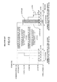
- FIG. 14 is a block diagram of a positioning unit that employs the fixed number of divisions method.
- a reference 102 is a speed adjustment control block
- 120 is a timing generating circuit
- 121 is a memory table
- 122 is a CPU or a computing unit (hereinafter, “computing unit”)
- 123 is a variable frequency pulse generating circuit
- 124 is position control circuit.
- the speed adjustment control block 102 includes the timing generating circuit 120 , the memory table 121 , and the computing unit 123 .
- a setting value, reference clock are input to the computing unit 122 from outside.
- the computing unit 122 calculates command speed Vp(j).
- the speed Vp(j) that is made to vary for each ⁇ ta(j) is expressed in terms of a reference clock frequency of the pulse generating circuit Vpp(j).
- the computing unit 122 also calculates speed variation timing ⁇ ta(j) during acceleration in terms of (1/base block frequency for interrupt signal) ⁇ tap(j) and remaining distance ⁇ Yd(g) during deceleration.
- the computing unit 122 writes the values of Vp(j), ⁇ ta(j), and ⁇ Yd(g) in the memory table 121 .
- the computing unit 122 divides the speed adjustment time by the number of divisions (fixed value) and provides the resultant value of the division to the timing generating circuit 120 .
- the timing generating circuit 120 generates an interrupt signal for each time interval provided and outputs to the computing unit 122 .
- the computing unit 122 varies the speed command using the data in the memory table 121 and outputs to the variable frequency pulse generating circuit 123 .
- the computing unit 122 outputs the control signal and the setting value related to position, current speed, and number of output pulses.
- the speed command generated in the speed adjustment control block 102 is provided to the variable frequency pulse generating circuit 123 thereby obtaining pulse string of variable frequency.
- the position control circuit 124 receives the pulse string, counts it and returns the number of output pulses to the speed adjustment control block 102 . In addition to this, the position control circuit 124 compares the control signal and the setting value related to position that are received from the speed adjustment control block 102 with number of output pulses, and generates deceleration start signal and stop signal. Thereafter, the position control circuit 124 outputs these signals to the speed adjustment control block 102 and to the variable frequency pulse generating circuit 123 . The deceleration starts when deceleration start signal is validated and the output pulse stops when the stop signal is validated.
- Vpp(j) is [([(number of divisions (Cvc) of
- Command speed Vp(g) that is made to vary for each ⁇ Yd(g) is expressed in terms of reference clock frequency of the pulse generating circuit and becomes [([(number of divisions (Cvc) of
- ⁇ tap(j) is equal to [([acceleration time/number of divisions (CTc) of acceleration time] ⁇ j ⁇ reference clock frequency for interrupt signal)—where numbers of five and above are rounded and anything under five is dropped].
- ⁇ Yd(g) is a remaining number of pulses of the output pulse which becomes [(Vpp(g) ⁇ reference clock frequency of the pulse generating circuit+initial speed) ⁇ (deceleration time/number of divisions (CTc) of the deceleration time) ⁇ g]/2.
- j (1, 2, . . . , (Cvc ⁇ 1), (Cvc))
- g (Cvc, (Cvc ⁇ 1), . . . , 2,1).
- FIG. 15 is a graph of speed variation in the fixed number of divisions method.
- a horizontal axis indicates time
- a vertical axis indicates speed
- an area indicates amount of shift (number of output pulses).
- the speed is varied by determining the amount of variation in speed, variation time, and the amount of shift remained when the number of divisions (Cvc) of
- [ ⁇ ta(j)] ⁇ (ta/CTc ⁇ j) indicates speed variation timing from the start of acceleration and after elapsing of time [ ⁇ ta(j)] the speed variation is controlled by varying speed increment [ ⁇ V(j)] with respect to V 0 .
- the variable frequency pulse generating circuit 123 is not activated at this stage.
- Japanese Patent Application laid open Publication No. 1998-42597 discloses a stationary recording disc in an information recording apparatus.
- This publication teaches use of an acceleration region that is increased in form of steps, for frequency step range ⁇ f a value obtained by dividing [target frequency (rated number of revolutions region) f 3 ⁇ starting speed f 2 ] by 8.
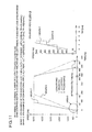
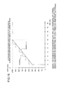
- FIG. 16 is a graphical representation of problems in the fixed time interval method.
- a graph 2 is obtained with the conventional fixed time interval method
- a graph 1 is obtained according to the present invention
- a graph 3 is obtained with another conventional fixed number of divisions method.
- the speed variation during acceleration in graph 2 is in the form of steep steps.
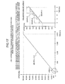
- FIG. 17 is a graphical representation of problems in the fixed number of divisions method.
- Graph 6 is obtained with the conventional fixed number of divisions method
- graph 4 is obtained according to the present invention
- graph 5 is obtained with another conventional fixed time interval method.
- the speed variation during acceleration in graph 6 is in the form of steep steps.
- the speed adjustment control method comprises a process of determining an amount of variation in speed [ ⁇ V(a/d)] from a data table of
- the speed variation interval [ ⁇ t(a/d)] is variable and provided independently from a control cycle that generates output pulses.
- speed adjustment control method prepared a data table with a process of inputting parameters the initial speed (V 0 ), a minimum value (VSmin) of the command speed, a maximum value (VSmax) of the command speed, the speed adjustment time [t(a/d)], a minimum value [t(a/d)min] of the speed adjustment time, a maximum value [t(a/d)max] of the speed adjustment time, a tolerance range condition [te(a/d)] of the speed adjustment time [t(a/d)], a condition for the amount of variation in speed, a control frequency (fc), and rank classification time (tWz) of the speed adjustment time; a process of determining a limit range (VWz) of speed difference based on the data mentioned above; a process of classifying
- is carried out by (VWz ⁇ power of 2) and classification of rank in the rank classification time (tWz) of the speed adjustment time [t(a/d)] is carried out by (tWz ⁇ power of 2).
- the amount of variation in speed [ ⁇ V(a/d)] is determined by minimum value of command speed (VSmin) ⁇ power of 2.
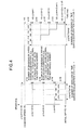
- FIG. 1 explains speed adjustment method (amount of variation in speed priority method) according to the present invention
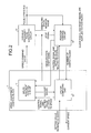
- FIG. 2 is a block diagram of a device that realizes the amount of variation in speed priority method according to the present invention
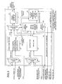
- FIG. 3 is a block diagram of a speed adjustment control circuit that realizes the amount of variation in speed priority method
- FIG. 4 is an illustration for explaining an example of speed change according to the present invention (amount of variation in speed priority method);
- FIG. 5 illustrates a method of making a data table of the amount of variation in speed [ ⁇ V(a/d)]
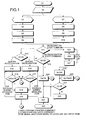
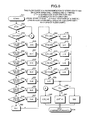
- FIG. 6 is an example of steps 36 to 44 in FIG. 5 expressed as a flowchart
- FIG. 8 is also an example expressed as a flowchart
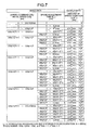
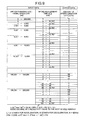
- FIG. 7 is a data table showing how to find out the amount of variation in speed [ ⁇ V(a/d)] during the speed adjustment time in this invention.
- FIG. 8 is an example when VWz in FIG. 7 is substituted by 2,000;
- FIG. 9 is a data table in which the amount of variation in speed [ ⁇ V(a/d)] is made smaller
- FIG. 10 is an illustration of calculation method of control frequency (fc);
- FIG. 11 is a comparison of speed adjustment time and positioning time between an example of this invention and that of conventional method
- FIG. 12 represents a whole block of the conventional fixed time interval method
- FIG. 13 is an example of speed change according to the conventional fixed time interval method
- FIG. 14 represents a whole block of the conventional fixed number of divisions method
- FIG. 15 is an example of speed change according to the conventional fixed number of divisions method
- FIG. 16 is a comparison of speed variation between an example of this invention and that of a conventional method at speed adjustment rate of 20[ks/kHz] and during acceleration from 400[Hz] to 1,000[Hz] in 12[ms];
- FIG. 17 is a comparison of speed variation between an example of this invention and that of a conventional invention at the speed adjustment rate of approximately 20[ms/kHz] and during acceleration from 400[Hz] to 1,000[Hz] in 2,000[ms].
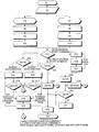
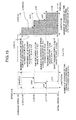
- FIG. 1 is a flowchart of an amount of variation in speed priority method, which is a speed variation control method, in this invention. This flowchart lists the procedure conducted by a speed adjustment control block 1 .
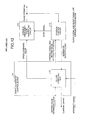
- FIG. 2 is a block diagram of a positioning unit that employs the speed variation control method according to the present invention.
- a reference numeral 1 represents a speed adjustment control block
- 11 represents a speed adjustment control circuit
- 12 represents a CPU or a computing unit
- 13 represents a variable frequency pulse generating circuit
- 14 represents a position control circuit.
- An example of construction of the variable frequency pulse generating circuit 13 is disclosed in Japanese Patent Application Laid Open Publication No. 1999-220364.
- a setting value, a reference clock, number of output pulses, a deceleration start signal, and a stop signal are input to the speed adjustment control block 1 from outside.
- the speed adjustment control block 1 generates a prescribed speed command and outputs a speed command value, setting value related to position, a control signal, and current speed.
- the speed command value generated in the speed adjustment control block 1 is provided to the variable frequency pulse generating circuit 13 and the variable frequency pulse generating circuit 13 obtains and outputs a pulse string (fout) of variable frequency.
- the position control circuit 14 receives and counts the pulse string and returns the number of output pulses to the speed adjustment control block 1 .
- the position control circuit 14 receives the control signal and the setting value related to position from the speed adjustment control block 1 and generates a deceleration signal and a stop signal.
- the position control circuit 14 outputs the deceleration start signal to the speed adjustment control block 1 and outputs the stop signal to the speed adjustment control block 1 and to the variable frequency pulse generating circuit 13 .
- the deceleration start signal is validated, the deceleration starts and when the stop signal is validated, the pulse string is not output.
- the computing unit 12 receives the setting value and the reference clock from outside.
- the computing unit 12 calculates and generates the control signal and the setting value related to speed and the control signal and the setting value related to position.
- the computing unit 12 outputs the control signal and the setting value related to speed to the speed adjustment control circuit 11 and outputs the control signal and the setting value related to position to the position control circuit 14 .
- the computing unit 12 outputs the number of output pulses received from the position control circuit 14 and the current speed received from the speed adjustment control circuit 11 to the outside.
- the speed adjustment control circuit 11 generates the speed command value based on the control signal and the setting value related to speed received from the computing unit 12 and the declaration start signal and the stop signal received from the position control circuit 14 and outputs the speed command value to the variable frequency pulse generating circuit 13 .
- FIG. 1 shows a control method executed by the speed adjustment control block 1 . Steps from S 1 to S 10 are processed in the computing unit 12 and steps from S 11 to S 29 are processed in the speed adjustment control circuit 11 .
- FIG. 3 is an illustration of internal structure of the speed adjustment control circuit 11 .
- 21 is a data selector- 1
- 22 is an adder-subtracter
- 23 is a data selector- 2
- 24 is a subtracter
- 25 is a data selector- 3
- 26 is a data comparator
- 27 is a speed command value Vp latch circuit
- 28 is a Vp latch timing generating circuit.
- step S 1 amount of variation in speed during acceleration ( ⁇ Va) and amount of variation in speed during deceleration ( ⁇ Vd) are determined using a [ ⁇ V(a/d)] data table. A value already determined is provided here. (explained later)
- step S 2 command speed (VS), initial speed (V 0 ), acceleration time (ta), deceleration time (td), amount of variation in speed during acceleration ( ⁇ Va), and amount of variation in speed during deceleration ( ⁇ Vd) are received as input.
- the acceleration is taken care of at step S 3 and the deceleration is taken care of at step S 7 .
- step S 3 previous command speed (VSb) or bias speed (VB) is taken as initial speed (V 0 ) during acceleration.
- step S 4 number of divisions of
- during acceleration time (Cva) are calculated by using Cva (
- step S 7 only bias speed (VB) is taken as initial speed in deceleration time.
- step S 8 number of divisions (Cvd) of
- is calculated by using Cva (
- the steps from S 1 to S 10 are carried out by the computing unit 12 as preparation before starting of pulse output.
- the speed adjustment control circuit configured as in FIG. 3 based on step 11 onward.
- step 11 it is checked whether a deceleration start command is received.
- process in step S 25 is carried out and when the deceleration start command is not received, process in step S 12 is carried out.
- step S 12 V 0 and Vs are compared with each other.
- V 0 VS
- process in step S 24 is carried out and when V 0 ⁇ VS, process in step S 13 is carried out.
- step S 13 V 0 and VS are compared with each other.
- V 0 >VS process in step S 16 is carried out and when V 0 ⁇ VS, process in step S 814 is carried out.
- the previous command speed (VSb) or bias speed (VB) is taken as initial value of VaVd.
- step S 15 VaVd and VS are compared with each other.
- VaVd ⁇ VS process in step S 24 is carried out and when VaVd ⁇ VS, process in step S 18 is carried out.
- step S 17 VaVd and VS are compared with each other.
- VaVd ⁇ VS process in step S 24 is carried out and when VaVd>VS, process in step S 18 is carried out.
- step S 18 ⁇ ta clock is generated.
- step S 19 VaVd is latched for each ⁇ ta. Further, for acceleration during acceleration time, steps S 14 , S 15 , S 18 , and S 19 are carried out for each ⁇ ta. On the other hand, for deceleration during acceleration time, steps S 16 , S 17 , S 18 , and S 19 are carried out for each ⁇ td.
- step S 21 Vp and VB are compared with each other.
- Vp>VB process in step S 23 is carried out and when Vp ⁇ VB, process in step S 22 is carried out.
- step S 22 previous Vp is held till stop.
- step S 23 Vp is latched and in step S 29 Vp is output to the variable frequency pulse-generating unit 13 .
- step S 24 Vp is taken as VS; in step S 23 , Vp is latched; and in step S 29 , Vp is output to the variable frequency pulse generating unit 13 .
- speed command value (Vp) or command speed (VS) is taken as initial value of Vd.
- step S 26 ⁇ td clock is generated.
- step S 27 Vd is latched for each ⁇ td.
- Steps S 25 to S 27 are carried out for each ⁇ td.
- FIG. 4 shows speed variation in the amount of variation in speed priority method, which is a speed variation control method in the present embodiment.
- the amount of variation in speed [ ⁇ V(a/d)] is determined using the data table taking precedence over speed variation interval [ ⁇ t(a/d)] and then number of divisions (Cv) of
- is determined by Cv(a/d) (
- t(a/d) is acceleration or deceleration time i.e., t(a) is acceleration time and t(d) is deceleration time.
- start up is carried out at a speed obtained by adding the amount of variation in speed ⁇ Va to the initial speed (V 0 ).
- Speed after the speed variation interval ⁇ ta is a value obtained by adding amount of variation in speed ⁇ Va to the previous speed and after elapsing of every speed variation interval ⁇ ta, the amount of variation in speed ⁇ Va is added to the previous speed to give speed. This is carried out iteratively.
- Speed after the speed variation interval ⁇ td is a value obtained by subtracting amount of variation in speed ⁇ Vd from the previous speed and after elapsing of every speed variation interval ⁇ td, the amount of variation in speed ⁇ Vd is subtracted from the previous speed to give speed. This is carried out repeatedly. Either command shift amount is attained or stops when stop command is provided.
- the method mentioned above can be realized by either of software and hardware.
- amount of variation in speed ⁇ V(a/d) is given precedence, number of divisions of speed during speed adjustment and number of divisions of speed adjustment time are kept variable, number of divisions is made to be maximum at all time. Since the speed adjustment is carried out by varying the output speed for each speed variation interval ⁇ t(a/d), the stepping motor can not lose synchronism easily. Moreover, the speed adjustment time, processing time till start up and tact time can be shortened and plurality of axes control can be realized.
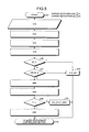
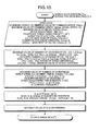
- FIG. 5 is a flowchart of a method for generating a data table of amount of variation in speed [ ⁇ V(a/d)] in this embodiment. This process is carried out by the computing unit 12 .
- Steps from S 31 to S 35 is a process already determined by the computing unit 12 and steps from S 36 to S 44 can also be expressed as shown in FIG. 6 .
- Step S 31 indicates starting of process.
- step S 32 data is received as input.
- command value (VS) minimum value of the command speed (VSmin), maximum value of the command speed (VSmax), initial speed (V 0 ), speed adjustment time [t(a/d)], minimum value of speed adjustment time [t(a,d)min], maximum value of the speed adjustment time [t(a,d)max], tolerance range condition [te(a/d)] of t(a,/d), condition of ⁇ V(a/d) (
- acceleration is represented by ‘a’ and deceleration is represented by ‘d’.
- step S 33 maximum value [CV(a/d)max] of number of divisions
- is calculated by using Cv(a/d)max (VWz/ ⁇ V(a/d)min) ⁇ (
- VSx V 0 x
- / ⁇ V(a/d) ⁇ Cvx ⁇ Cv(a/d)max, limit range (VWz) of speed difference is calculated by using VWz
- , and minimum value of amount of variation in speed [ ⁇ V(a/d)] is calculated by using ⁇ V(a/d)min VSmin.
- An example of method for determining a suitable value is [te(a/d) ⁇ fc].
- VWz [Cv(a/d)max ⁇ V(a/d)min].
- step S 36 t(a/d) is compared with 0.
- step S 37
- process in step S 43 is carried out when
- step S 38 rank (K) of
- is taken as K 0, 1, 2, . . . (integer) and calculated by using [VWz ⁇ ((K ⁇ 1)th power of 2)+ ⁇ V(a/d)]min ⁇
- step S 40 K is compared with L. If K>L, process in step S 42 is carried out; and if K ⁇ L, process in step S 41 is carried out.
- step S 44 ⁇ V(a/d) is output to speed adjustment control process and the process is terminated.
- steps from S 36 to S 44 can be expressed as shown in FIG. 6 .
- Steps S 36 to S 44 in FIG. 5 based on flowchart in FIG. 6 .
- Step S 51 indicates start of process.
- step S 53
- 0, process in step S 83 is carried out; if
- step S 54
- step S 56
- process in step S 57 is carried out and K is substituted by 1.
- process in step S 58 is carried out.
- step S 58
- process in step S 59 is carried out and K is substituted by 2.
- process in step S 60 is carried out.
- step S 60
- process in step S 61 is carried out and K is substituted by 3.
- process in step S 62 is carried out.
- step S 62
- process in step S 63 is carried out and K is substituted by 4.
- process in step S 64 is carried out.
- step S 64
- process in step S 65 is carried out and K is substituted by 5.
- process in step S 66 is carried out.
- step S 66
- process in step S 67 is carried out and K is substituted by 6.
- process in step S 68 is carried out.
- step S 68 k is substituted by 7.
- step S 69 t(a/d) is compared with 1,024.
- process in step S 70 is carried out and L is substituted by 0.
- process in step S 71 is carried out.
- step S 71 t(a/d) is compared with 2,048.
- process in step S 72 is carried out and L is substituted by 1.
- process in step S 73 is carried out.
- step S 73 t(a/d) is compared with 4,096.
- process in step S 74 is carried out and L is substituted by 2.
- process in step S 75 is carried out.
- step S 75 t(a/d) is compared with 8,192.
- process in step S 76 is carried out and L is substituted by 3.
- process in step S 77 is carried out.
- step S 77 t(a/d) is compared with 16,384.
- process in step S 78 is carried out and L is substituted by 4.
- process in step S 79 is carried out.
- step S 79 L is substituted by 5.
- step S 80 K is compared with L.
- process in step S 82 is carried out.
- K ⁇ L process in step S 81 is carried out and ⁇ V(a/d) is substituted by 1.
- step S 83 ⁇ V(a/d) is substituted by 0.
- step S 84 ⁇ V(a/d) is output to the speed adjustment control process and terminated.
- the method mentioned above can be realized by either of software and hardware.
- FIG. 7 is a data table for calculation of amount of variation in speed ⁇ V(a/d) in the present embodiment. These are the results obtained when the process in the flowchart in FIG. 5 is carried out.
- the data table in this figure provides
- FIG. 9 in order to make ⁇ V(a/d) narrower, ⁇ V is made to vary for each ⁇ V(a/d)min.
- tWz cannot be a fixed value.
- ⁇ V(a/d) is taken as (K ⁇ L)th power of 2, as shown in FIG. 8 , in the present embodiment.
- FIG. 10 is flowchart of a method for calculation of the control frequency (fc). This flowchart is provided only for reference and, therefore, will not be explained in detail.
- the number of divisions of accelerated or decelerated speed and the number of divisions of speed adjustment time are made variable while giving precedence to the amount of variation in speed ⁇ V(a/d), the number of divisions is made maximum all the time, and the speed adjustment is carried out by varying the output speed for each speed variation interval ⁇ t(a/d).
- the synchronism of stepping motor cannot be lost so easily, it is possible to shorten the speed adjustment time and the processing time before start up, and the tact time and plurality axes control can be brought into practice at low cost.
- the tact time is a time taken for one process and in this case, positioning operation is considered as one process.
- the acceleration and deceleration time, and the processing time before start up become short, the operating time for positioning of same amount of shift becomes short.
- the amount of such delay or advancement varies according to the speed. When the amount goes beyond certain value, the motor cannot follow pulse speed and loses synchronism (causes misstepping). The speed just before losing synchronism is called as the self-start up frequency.
- the rate of speed adjustment determined by the above equation has to be greater than or equal to the value of the rate of speed adjustment of the stepping motor (approximately from 20 to 30) that is used.
- the rate of speed adjustment determined by the calculation is less than the value of the rate of speed adjustment of the stepping motor, it is necessary to carry out changes like extending the set speed adjustment time.
- actual speed adjustment time is determined from rate of speed adjustment ⁇ 20[ms/kHz]. Since the rate of speed adjustment 20 ⁇ speed adjustment time/
- 92[ms].
- the minimum speed adjustment time that satisfies the condition ⁇ V(a/d) ⁇ 50[Hz] is determined.
- the minimum speed adjustment time that satisfies the condition of ⁇ V ⁇ 50[Hz] is 92[ms].
- the minimum speed adjustment time, which satisfies the condition ⁇ V(a/d) ⁇ 50[Hz] is 182[ms].
- the amount of variation in speed ⁇ V(a/d) is determined using the data table, the number of divisions of accelerated or decelerated speed and the number of divisions of speed adjustment time are made variable, number of divisions is made maximum all the time, speed adjustment is carried out by varying the output speed for each speed variation interval ⁇ t(a/d).
- the speed adjustment control method according to the present invention is suitable for speed variation control of the stepping motor.
Applications Claiming Priority (3)
| Application Number | Priority Date | Filing Date | Title |
|---|---|---|---|
| JP2001052117A JP3783567B2 (ja) | 2001-02-27 | 2001-02-27 | 加減速制御方法 |
| JP2001-52117 | 2001-02-27 | ||
| PCT/JP2002/000964 WO2002069484A1 (fr) | 2001-02-27 | 2002-02-06 | Procede de commande d'acceleration et de deceleration |
Publications (2)
| Publication Number | Publication Date |
|---|---|
| US20040088061A1 US20040088061A1 (en) | 2004-05-06 |
| US6859752B2 true US6859752B2 (en) | 2005-02-22 |
Family
ID=18912796
Family Applications (1)
| Application Number | Title | Priority Date | Filing Date |
|---|---|---|---|
| US10/469,010 Expired - Lifetime US6859752B2 (en) | 2001-02-27 | 2002-02-06 | Speed adjustment control method |
Country Status (5)
| Country | Link |
|---|---|
| US (1) | US6859752B2 (ja) |
| JP (1) | JP3783567B2 (ja) |
| KR (1) | KR100556657B1 (ja) |
| DE (1) | DE10296377T5 (ja) |
| WO (1) | WO2002069484A1 (ja) |
Families Citing this family (4)
| Publication number | Priority date | Publication date | Assignee | Title |
|---|---|---|---|---|
| JP2006246671A (ja) * | 2005-03-07 | 2006-09-14 | Seiko Epson Corp | ステッピングモータ制御装置、ステッピングモータ制御方法、および、ステッピングモータ制御プログラム |
| JP2008011655A (ja) * | 2006-06-29 | 2008-01-17 | Hitachi High-Technologies Corp | パルスモータ制御装置 |
| US10862410B2 (en) * | 2016-12-22 | 2020-12-08 | Nidec Corporation | Multi-motor system |
| EP3570124A1 (de) * | 2018-05-16 | 2019-11-20 | Siemens Aktiengesellschaft | Reglerstruktur für gemischt direkten/indirekten antrieb eines maschinenelements |
Citations (11)
| Publication number | Priority date | Publication date | Assignee | Title |
|---|---|---|---|---|
| US4528491A (en) | 1982-12-28 | 1985-07-09 | Tokyo Keiki Company, Ltd. | Pulse motor control apparatus |
| JPS60187123A (ja) | 1984-03-07 | 1985-09-24 | Fuji Electric Co Ltd | 可変周波数パルス発生装置 |
| JPH07163195A (ja) | 1993-12-02 | 1995-06-23 | Hitachi Ltd | ステッピングモータコントローラ |
| JPH07168626A (ja) | 1993-12-15 | 1995-07-04 | Matsushita Electric Works Ltd | 加減速制御方法 |
| JPH07250498A (ja) | 1994-03-11 | 1995-09-26 | Mitsubishi Electric Corp | パルスモータの速度制御方法およびその装置 |
| JPH09261015A (ja) | 1996-03-19 | 1997-10-03 | Japan Radio Co Ltd | 周波数可変のパルス波形発生回路 |
| JPH1042597A (ja) | 1996-07-22 | 1998-02-13 | Minebea Co Ltd | 情報記録装置の記録円盤駆動方式 |
| JPH10257244A (ja) | 1997-03-12 | 1998-09-25 | Minolta Co Ltd | 移動体駆動装置 |
| JPH11220364A (ja) | 1998-01-30 | 1999-08-10 | Mitsubishi Electric Corp | 可変周波数パルス発生装置 |
| JP2000139099A (ja) | 1998-11-02 | 2000-05-16 | Hitachi Ltd | モータ制御装置 |
| US20030105573A1 (en) * | 2000-05-16 | 2003-06-05 | Takeshi Ishizu | Gear shifting on target speed reduction in vehicle speed control system |
-
2001
- 2001-02-27 JP JP2001052117A patent/JP3783567B2/ja not_active Expired - Lifetime
-
2002
- 2002-02-06 DE DE10296377T patent/DE10296377T5/de not_active Ceased
- 2002-02-06 US US10/469,010 patent/US6859752B2/en not_active Expired - Lifetime
- 2002-02-06 WO PCT/JP2002/000964 patent/WO2002069484A1/ja active IP Right Grant
- 2002-02-06 KR KR1020037011159A patent/KR100556657B1/ko not_active IP Right Cessation
Patent Citations (12)
| Publication number | Priority date | Publication date | Assignee | Title |
|---|---|---|---|---|
| US4528491A (en) | 1982-12-28 | 1985-07-09 | Tokyo Keiki Company, Ltd. | Pulse motor control apparatus |
| JPS60187123A (ja) | 1984-03-07 | 1985-09-24 | Fuji Electric Co Ltd | 可変周波数パルス発生装置 |
| JPH07163195A (ja) | 1993-12-02 | 1995-06-23 | Hitachi Ltd | ステッピングモータコントローラ |
| JPH07168626A (ja) | 1993-12-15 | 1995-07-04 | Matsushita Electric Works Ltd | 加減速制御方法 |
| JPH07250498A (ja) | 1994-03-11 | 1995-09-26 | Mitsubishi Electric Corp | パルスモータの速度制御方法およびその装置 |
| JPH09261015A (ja) | 1996-03-19 | 1997-10-03 | Japan Radio Co Ltd | 周波数可変のパルス波形発生回路 |
| JPH1042597A (ja) | 1996-07-22 | 1998-02-13 | Minebea Co Ltd | 情報記録装置の記録円盤駆動方式 |
| US6078457A (en) | 1996-07-22 | 2000-06-20 | Minebea Co., Ltd. | Driving method for a stepping motor |
| JPH10257244A (ja) | 1997-03-12 | 1998-09-25 | Minolta Co Ltd | 移動体駆動装置 |
| JPH11220364A (ja) | 1998-01-30 | 1999-08-10 | Mitsubishi Electric Corp | 可変周波数パルス発生装置 |
| JP2000139099A (ja) | 1998-11-02 | 2000-05-16 | Hitachi Ltd | モータ制御装置 |
| US20030105573A1 (en) * | 2000-05-16 | 2003-06-05 | Takeshi Ishizu | Gear shifting on target speed reduction in vehicle speed control system |
Non-Patent Citations (1)
| Title |
|---|
| International Search Report for PCT/JP02/00964 dated May 21, 2002. |
Also Published As
| Publication number | Publication date |
|---|---|
| JP3783567B2 (ja) | 2006-06-07 |
| JP2002262596A (ja) | 2002-09-13 |
| KR100556657B1 (ko) | 2006-03-07 |
| DE10296377T5 (de) | 2004-04-15 |
| WO2002069484A1 (fr) | 2002-09-06 |
| KR20030078084A (ko) | 2003-10-04 |
| US20040088061A1 (en) | 2004-05-06 |
Similar Documents
| Publication | Publication Date | Title |
|---|---|---|
| US5304907A (en) | Servo system that controls a motor and compensates for system irregularities | |
| US5142226A (en) | Position detection device having absolute position detection apparatus and interpolation apparatus | |
| Lee et al. | Improved velocity estimation for low-speed and transient regimes using low-resolution encoders | |
| US6859752B2 (en) | Speed adjustment control method | |
| JPH0983355A (ja) | デジタルpll回路並びにこれに用いられるデジタル周波数調整回路及びデジタル位相調整回路、並びに半導体装置 | |
| JP3949134B2 (ja) | ステッピングモータの制御装置 | |
| JPH11178380A (ja) | モータ速度制御装置 | |
| JPH10301630A (ja) | 検出位置データ送信出力装置 | |
| KR20030075178A (ko) | 위치결정 제어방법 | |
| JP6740795B2 (ja) | 速度制御システム | |
| JP4201886B2 (ja) | Dcブラシレスモータの速度制御装置 | |
| JP3018576B2 (ja) | ジッタ補正装置 | |
| JPH10252549A (ja) | 回転数検出装置及び回転機械の制御装置 | |
| JPH03164084A (ja) | モータの回転数制御装置 | |
| JPS58192481A (ja) | モ−タの速度制御装置 | |
| JPH0627436Y2 (ja) | 作図機のペンヘツド送り装置 | |
| KR20010083860A (ko) | 마이크로 스텝핑모터의 구동장치 | |
| JPH05188066A (ja) | サーボモータの速度検出装置 | |
| JPH05188068A (ja) | サーボモータの速度検出装置 | |
| JP3982766B2 (ja) | ステッピングモータの制御装置 | |
| JPH03113378A (ja) | 指示計器の駆動方法 | |
| JPH0130395B2 (ja) | ||
| JPH07168626A (ja) | 加減速制御方法 | |
| JPH04281381A (ja) | 電動機の瞬時位置・瞬時速度・瞬時加速度検出装置、ならびに瞬時位置値・瞬時速度値・瞬時加速度値を用いた電動機の制御方法 | |
| JPS5996887A (ja) | サ−ボモ−タの回転数制御方法 |
Legal Events
| Date | Code | Title | Description |
|---|---|---|---|
| AS | Assignment |
Owner name: MITSUBISHI DENKI KABUSHIKI KAISHA, JAPAN Free format text: ASSIGNMENT OF ASSIGNORS INTEREST;ASSIGNOR:NAKASHIMA, YASUHIRO;REEL/FRAME:014812/0378 Effective date: 20030701 |
|
| STCF | Information on status: patent grant |
Free format text: PATENTED CASE |
|
| FPAY | Fee payment |
Year of fee payment: 4 |
|
| FPAY | Fee payment |
Year of fee payment: 8 |
|
| FPAY | Fee payment |
Year of fee payment: 12 |