US6830261B2 - Inflatable airbag and method of making the same - Google Patents
Inflatable airbag and method of making the same Download PDFInfo
- Publication number
- US6830261B2 US6830261B2 US09/884,541 US88454101A US6830261B2 US 6830261 B2 US6830261 B2 US 6830261B2 US 88454101 A US88454101 A US 88454101A US 6830261 B2 US6830261 B2 US 6830261B2
- Authority
- US
- United States
- Prior art keywords
- woven
- bag
- joints
- invention according
- gas
- Prior art date
- Legal status (The legal status is an assumption and is not a legal conclusion. Google has not performed a legal analysis and makes no representation as to the accuracy of the status listed.)
- Expired - Fee Related
Links
- 238000004519 manufacturing process Methods 0.000 title description 6
- 239000004744 fabric Substances 0.000 claims abstract description 69
- 230000004888 barrier function Effects 0.000 claims abstract description 42
- 238000010276 construction Methods 0.000 claims description 16
- 238000000576 coating method Methods 0.000 claims description 5
- 229920000728 polyester Polymers 0.000 claims description 5
- 239000004677 Nylon Substances 0.000 claims description 4
- 229920002292 Nylon 6 Polymers 0.000 claims description 4
- 230000000903 blocking effect Effects 0.000 claims description 4
- 239000011248 coating agent Substances 0.000 claims description 4
- 229920001778 nylon Polymers 0.000 claims description 4
- 235000004879 dioscorea Nutrition 0.000 claims 2
- 229920000642 polymer Polymers 0.000 claims 2
- 239000007789 gas Substances 0.000 abstract description 10
- 238000009941 weaving Methods 0.000 description 25
- 230000015572 biosynthetic process Effects 0.000 description 8
- 238000000034 method Methods 0.000 description 5
- 239000002759 woven fabric Substances 0.000 description 5
- 230000008901 benefit Effects 0.000 description 3
- 230000005465 channeling Effects 0.000 description 3
- 230000000295 complement effect Effects 0.000 description 3
- 230000008569 process Effects 0.000 description 3
- 230000001681 protective effect Effects 0.000 description 3
- 238000003780 insertion Methods 0.000 description 2
- 230000037431 insertion Effects 0.000 description 2
- 230000035699 permeability Effects 0.000 description 2
- 239000004952 Polyamide Substances 0.000 description 1
- 230000009471 action Effects 0.000 description 1
- 230000009286 beneficial effect Effects 0.000 description 1
- 230000007812 deficiency Effects 0.000 description 1
- 238000010586 diagram Methods 0.000 description 1
- 230000000694 effects Effects 0.000 description 1
- 239000002360 explosive Substances 0.000 description 1
- 238000009986 fabric formation Methods 0.000 description 1
- 230000003993 interaction Effects 0.000 description 1
- 238000012423 maintenance Methods 0.000 description 1
- 239000000463 material Substances 0.000 description 1
- 239000000203 mixture Substances 0.000 description 1
- 229920000058 polyacrylate Polymers 0.000 description 1
- 229920002647 polyamide Polymers 0.000 description 1
- 229920001296 polysiloxane Polymers 0.000 description 1
- 229920002635 polyurethane Polymers 0.000 description 1
- 239000004814 polyurethane Substances 0.000 description 1
- 230000002035 prolonged effect Effects 0.000 description 1
- 238000007789 sealing Methods 0.000 description 1
- 230000007704 transition Effects 0.000 description 1
- XLYOFNOQVPJJNP-UHFFFAOYSA-N water Substances O XLYOFNOQVPJJNP-UHFFFAOYSA-N 0.000 description 1
Images


Classifications
-
- B—PERFORMING OPERATIONS; TRANSPORTING
- B60—VEHICLES IN GENERAL
- B60R—VEHICLES, VEHICLE FITTINGS, OR VEHICLE PARTS, NOT OTHERWISE PROVIDED FOR
- B60R21/00—Arrangements or fittings on vehicles for protecting or preventing injuries to occupants or pedestrians in case of accidents or other traffic risks
- B60R21/02—Occupant safety arrangements or fittings, e.g. crash pads
- B60R21/16—Inflatable occupant restraints or confinements designed to inflate upon impact or impending impact, e.g. air bags
- B60R21/23—Inflatable members
- B60R21/235—Inflatable members characterised by their material
-
- D—TEXTILES; PAPER
- D03—WEAVING
- D03D—WOVEN FABRICS; METHODS OF WEAVING; LOOMS
- D03D1/00—Woven fabrics designed to make specified articles
- D03D1/02—Inflatable articles
-
- B—PERFORMING OPERATIONS; TRANSPORTING
- B60—VEHICLES IN GENERAL
- B60R—VEHICLES, VEHICLE FITTINGS, OR VEHICLE PARTS, NOT OTHERWISE PROVIDED FOR
- B60R21/00—Arrangements or fittings on vehicles for protecting or preventing injuries to occupants or pedestrians in case of accidents or other traffic risks
- B60R21/02—Occupant safety arrangements or fittings, e.g. crash pads
- B60R21/16—Inflatable occupant restraints or confinements designed to inflate upon impact or impending impact, e.g. air bags
- B60R21/23—Inflatable members
- B60R21/235—Inflatable members characterised by their material
- B60R2021/23533—Inflatable members characterised by their material characterised by the manufacturing process
- B60R2021/23542—Weaving
- B60R2021/23547—Weaving one piece weaving
-
- B—PERFORMING OPERATIONS; TRANSPORTING
- B60—VEHICLES IN GENERAL
- B60R—VEHICLES, VEHICLE FITTINGS, OR VEHICLE PARTS, NOT OTHERWISE PROVIDED FOR
- B60R21/00—Arrangements or fittings on vehicles for protecting or preventing injuries to occupants or pedestrians in case of accidents or other traffic risks
- B60R21/02—Occupant safety arrangements or fittings, e.g. crash pads
- B60R21/16—Inflatable occupant restraints or confinements designed to inflate upon impact or impending impact, e.g. air bags
- B60R21/23—Inflatable members
- B60R21/231—Inflatable members characterised by their shape, construction or spatial configuration
- B60R21/232—Curtain-type airbags deploying mainly in a vertical direction from their top edge
Definitions
- the present invention relates to an inflatable cushion and more particularly to a safety device for use in a motor vehicle.
- the present invention is particularly useful in application as an inflatable side curtain for disposition between a vehicle occupant and the vehicle frame during a roll-over event.
- Inflatable protection cushions used in passenger vehicles are a component of a relatively complex system.
- the main elements of such a system are: an impact sensing system, an ignition system, a gas producing device, an attachment device, a system enclosure and an inflatable protective cushion.
- the gas is released causing an explosive release of gas filling the cushion to a deployed state which can absorb the impact of the forward movement of a body.
- Such cushions were initially used to protect the operator of a vehicle and were stored within the steering column for this purpose.
- Such driver side cushions are described in U.S. Pat. No. 5,533,755 to Nelsen et al. (incorporated by reference). Cushions for the protection of vehicle passengers have gained acceptance and are typically stored in the dash panel in opposing relation to the passenger seat. Recently, the use of cushions for the protection of drivers and occupants in side-impact collisions has gained general acceptance.
- One cushion configuration for use in the protection of vehicle occupants during a side-impact collision is the so called side curtain configuration which is stored at the roof line and connected along the door frame.
- One embodiment of such a side curtain is illustrated and described in U.S. Pat. No. 5,788,270 to HAland et al., the teachings of which are incorporated herein by reference.
- one of the purposes of the side curtain configuration is to remain inflated for a relatively long period of time so as to provide protection to the vehicle occupants in the event of a protracted roll-over event.
- the side curtain must remain inflated in order to be effective. Accordingly, uncontrolled or excessive release of the inflation media through seams or other connective links within the side curtain is undesirable.
- the curtain be of such a configuration as to provide substantial protection over an extremely large area during its operation.
- its configuration in order for the side curtain to perform, its configuration must be such as to provide an effective expanded profile while at the same time providing for the rapid efficient channeling of the inflation media to all areas of the cushion which are to be inflated.
- side cushions such as those described in HAland et al. have been configured so as to have a relatively thin profile of about 30-40 millimeters upon inflation. Such a thin profile is achieved by interweaving the fabrics forming the front and the back of the curtain at selected locations during formation of the curtain on a jacquard controlled loom.
- interweaving technique as utilized by HAland is described in detail in International Patent Publication WO/90/09295 which corresponds to U.S. Pat. No. 5,685,347 to Graham et al. the teachings of which are incorporated herein by reference.
- interweaving and consequential control of the shape of the airbag may be effected through use of a loom having programming means such as a jacquard system.
- jacquard systems introduces a high level of complexity into the formation process.
- a jacquard system uses a complex computer controlled process or a series of punched cards wherein each card perforation controls the action of a single warp thread for the passage of a single pick. A separate card is utilized for each pick in a given pattern. Aside from the basic complexity, jacquard weaving also has the inherent deficiency and limitation of relying upon relatively expensive equipment.
- an inflatable airbag cushion is provided.
- the cushion is in the form of a bag of non-sewn dobby woven construction.
- the bag includes a face portion and a rear portion which face and rear portions are formed from first and second fabric layers.
- the fabric layers are woven simultaneously on the same loom according to weave patterns controlled by manipulation of the of warp harnesses.
- Each of the fabric layers is defined by a multiplicity of warp yarns running in the warp direction interposed by a multiplicity of weft yarns running in the weft direction which is substantially transverse to the warp direction. So as to maintain the bag in a relatively flat condition once inflated, and to channel the inflation gasses throughout the structure, the bag includes a multiplicity of woven in joints.
- These woven in joints are arranged so as to define connective points and flow barriers between the face portion and the rear portion of the bag such that upon introduction of the flow of a gas into the bag, expansion is limited by the woven in joints thereby channeling the gas to locations where inflation is desired while simultaneously restricting inflation of the bag at the locations where such woven in joints are present. At least a portion of the woven in joints preferably extend in substantially straight lines in both the warp direction and the fill direction. The woven in joints form an inflatable portion having more than four interior sides.
- a method for forming the bag for a side curtain protective cushion by weaving on a dobby control loom whereby straight line weave patterns are repeated across the width of the loom so as to simultaneously form two layers of fabric with woven in joints disposed at selected locations across the length and width of the fabric thereby defining interconnections between the fabric layers.
- FIG. 1 illustrates the face portion of one embodiment of an inflatable restraint cushion formed according to the present invention.
- FIG. 2 illustrates the face portion of one embodiment of an inflatable restraint cushion formed according to the present invention.
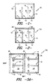
- FIG. 3A illustrates a possible layout 200 for on loam production of the inflatable restraint cushion 110 shown in FIG. 2 .
- FIG. 3B illustrates a possible arrangement of an inflatable cushion 210 for on loom production of tubular structures having interwoven joints sealing the edges along the warp direction.
- FIGS. 4A-4D illustrate the four basic plain weave patterns utilized in formation of the bag according to the preferred practice of the present invention.
- FIG. 5 illustrates a potentially preferred embodiment of a woven in joint extending along the warp direction of the inflatable restraint cushion according to the present invention.
- FIG. 6 illustrates a potentially preferred embodiment of a woven in joint extending along the weft direction of the inflatable restraint cushion according to the present invention.
- FIG. 7 illustrates exemplary woven in joints formed across the surface of a fabric according to the present invention.
- FIG. 8 illustrates a dobby woven bag 310 according to the present invention including a multiplicity of vertical line connections formed by woven in joints extending across the interior of the bag.
- FIG. 9 Illustrates a bag 410 according to the present invention including a multiplicity of substantially point connections formed by short woven in joints extending between the face and the rear of the bag.
- FIG. 10 illustrates an arrangement of horizontal and vertical interwoven connections extending across the interior of the restraint cushion 510 according to the present invention.
- non-sewn cushion generally designated by reference numeral 10 .
- the non-sewn cushion 10 includes an aperture 12 for introduction of an inflation media into the interior.
- a plurality of flow barrier elements 14 disposed across the interior and along the perimeter of the cushion 10 are a plurality of flow barrier elements 14 .
- these flow barrier elements 14 are formed by combinations of woven in joints 16 which are disposed in both fabric directions. That is, a portion of the woven in joints are preferably disposed in the vertical direction while a second portion of the woven in joints are preferably disposed in the horizontal direction.
- each of the barrier elements 14 includes an extended box configuration 20 disposed adjacent the upper edge portion of the cushion.
- extended box configurations are believed to be useful in channeling inflation media throughout a cushion of extended length such as may be used in a side-curtain application.
- the extended box configuration preferably includes a stepped corner profile so as to have two or more corners so as to distribute the stress of inflation more uniformly at these locations.
- the woven in joints forming the flow barrier elements 14 are of substantially straight line configuration. It has been found that even relatively complex geometries such as those illustrated in FIG. 2 may be formed at the point of fabric weaving by controlling a small number of weave harnesses without the need to use a substantially more complex and expensive jacquard weaving system. By way of example only, it is been found that dobby control looms with thirty-six or fewer harnesses are adequate to manufacture even very complex structures. The structure shown in FIG. 2 can be made on a loom of twenty harnesses or fewer.
- two layers of woven fabric 24 are simultaneously formed on a loom which feeds weft yarns between a plurality of warp yarns by well known insertion means such as air jets, water jets or projectiles while intermittently raising and lowering the plane of the warp yarns with respect to the path of travel of the weft yarns so as to form an interwoven structure as is well known to those of skill in the art.
- insertion means such as air jets, water jets or projectiles
- Such weaving is described, for example in U.S. Pat. No. 5,421,378 to Bower et al. the teachings of which are incorporated herein by reference.
- two distinct fabric layers may be formed on the same loom simultaneously by threading the harnesses of the loom with two sets of warp yarns and alternating the shed opening between the two sets of warp yarns as each pick (i.e. weft yarn) is inserted.
- Joints between the two layers of fabric may be formed in both the warp direction and the fill direction by crossing yarns from one layer to the other as will be described more fully below.
- a joint may be formed which runs in the warp direction by shifting weft yarns from the top layer of fabric to the bottom layer while a joint may be formed in the weft direction by crossing the warp yarns.
- FIG. 3A there is illustrated one potential layout for the formation of on loom bags including barrier element configurations as illustrated in FIG. 2 .
- each joint which makes up the flow barrier elements 14 is formed by a yarn shift between fabric layers.
- the creation of such joints may be started and stopped at will by the simple control of harnesses during the weaving operation.
- a plurality of the woven in joints 16 define closed parameter joints and form a closed edge or end between the top and bottom layers of fabric.
- the requisite control of the weaving process to form the joints in desired locations is achieved by dividing the fabric width into a multiplicity of zones of width which are dependant upon the ultimate desired geometry of the element to be produced.
- warp yarns for each of these zones are attached to a different set of control harnesses than the warp yarns of the adjacent zone. Since two layers of fabric are being formed, a minimum of four harnesses control the movement of the warp yarns in each zone.
- the warp yarns for each weaving zone may be spread across the depth of all harnesses.
- one quarter of the warp yarns for the first weaving zone will be carried by harness number one
- one quarter of the warp yarns for the first weaving zone will be carried by harness number 4
- one quarter of the warp yarns for the first weaving zone will be carried by harness number 7
- one quarter of the warp yarns for the first weaving zone will be carried by harness number 10 .
- the warp yarns for the second and third weaving zones can be similarly distributed amongst the available harnesses.
- two layers of woven fabric 24 are formed simultaneously from polymeric yarn such as polyester, nylon 6 or nylon 6.6 using four repeat patterns each of which incorporates four warp yarns and four weft yarns. Repeat patterns which utilize four yarns in each weaving direction permit the simultaneous formation of two layers of the potentially preferred plain weave configuration using a single weaving machine. Moreover, the repetition of a given weave pattern across the length and width of the fabric gives rise to two layers which are uniform and independent and one another. Subsequent to formation, portions of the fabric 24 may be coated with permeability blocking materials 25 including by way of example only, silicone, polyamides, polyurethane, polyacrylates and mixtures thereof.
- such coatings will be present at levels of not greater than 1 ounce per square yard of fabric, more preferably not greater than about 0.6 ounces per square yard of fabric, and most preferably not greater than about 0.4 ounces per square yard such that the coating inhabits the interstitial voids between the yarns without substantially covering the yarns themselves.
- FIGS. 4A-4D potentially preferred four yarn repeat patterns useful in accordance with the present invention are illustrated.
- warp yarns 1 and 3 in each weave pattern will be disposed in the same layer of fabric 24 while warp yarns 2 and 4 are disposed in the other layer.
- weft yarns “A” and “C” should be in one layer while weft yarns “B” and “D” are disposed in the other layer. Accordingly, when weaving the pattern according to FIG.
- weft yarn “A” when weft yarn “A” is inserted it passes over warp yarns 1 , 2 , 3 and under warp yarn 4 so as to form part of a first fabric layer.
- weft yarn “B” When weft yarn “B” is inserted it passes over warp yarn 1 and under warp yarns 2 , 3 , and 4 so as to form part of a second fabric layer.
- warp yarn “C” When warp yarn “C” is inserted, it passes over warp yarns 1 , 3 and 4 while passing under warp yarn 2 .
- weft yarn “D” when weft yarn “D” is inserted it passes under warp yarns 1 , 2 and 4 and over warp yarn 3 so as to complete one interaction of weaving in the second fabric layer.
- a first or top layer of fabric is formed from warp yarns 2 and 4 and weft yarns “A” and “C” and a second or bottom layer of fabric is formed from warp yarns 1 and 3 and weft yarns “B” and “D”.
- the first or top layer contains warp yarns 1 and 3 and weft yarns “A” and “C” while the second or bottom layer contains warp yarns 2 and 4 and weft yarns “B” and “D”.
- the first or top layer contains warp yarns 2 and 4 and weft yarns “B” and “D” and the second or bottom layer contains warp yarns 1 and 3 and weft yarns “A” and “C”.
- the first or top layer contains warp yarns 1 and 3 and weft yarns “B” and “D” and the second or bottom layer contains warp yarns 2 and 4 and weft yarns “A” and “C”.
- a two layered fabric 24 having a top layer 30 and a bottom layer 32 (FIGS. 5 and 6) each of which include a multiplicity of warp yarns interwoven with a multiplicity of weft or filling yarns as illustrated in FIGS. 5 and 6 may thus be formed by combining the weave patterns illustrated in FIGS. 4A-4D.
- interconnective joints 16 of a substantially gas impermeable nature may be formed between the top and bottom layers 30 , 32 of the woven fabric structure 24 .
- a yarn float for this purpose is defined as the occurrence of a warp or a weft yarn that passes either over or under two or more consecutive transverse yarns such that it does not pass between such transverse yarns. That is, in the preferred embodiment, the over-under interwoven relationship between warp yarns and weft yarns is maintained across the joint 16 even though either the warp yarns or the weft yarns may shift from the top layer 30 to the bottom layer 32 . This shift preferably occurs within the space of a single yarn.
- This feature of the present invention is believed to represent a substantial and important advantage over prior interwoven connections which typically give rise to skipped yarns and/or require the use of fairly significant interwoven zones where the top layer and the bottom layer are formed into a single thick bulky layer for at least several yarn positions to provide interconnection.
- the flow barrier elements 14 are made up of relatively closely spaced joints 16 so as to protect against undue slippage which is believed to increase permeability and to guard against breakage.
- no more than twelve yarns in each layer of fabric (twenty-four total yarns) will be disposed in the region between the closely spaced joints.
- no more than eight yarns in each layer of fabric will be disposed between the closely spaced joints.
- only about two to four yarns in each layer of fabric will be disposed in the region between the closely spaced joints (FIGS. 5 and 6 ).
- complementary closely spaced joints separated by two independent layers of fabric according to the present invention may also be formed in a curved format if a jacquard weaving system is utilized.
- the joints which are formed between the top layer 30 and bottom layer 32 are achieved by transitioning between complementary weave patterns such as those illustrated in FIGS. 4A-4D.
- complementary weave patterns such as those illustrated in FIGS. 4A-4D.
- FIG. 5 there is illustrated an example wherein a first pattern 40 such as pattern 4 A is in a weave zone adjacent to another weave zone utilizing a second pattern 42 such as illustrated in FIG. 4D so as to effect a shift of the weft yarns from the top layer 30 to the bottom layer 32 .
- a similar joint is then formed in close proximity by switching back to the first pattern 40 .
- FIG. 6 there is illustrated a pair of joints extending in the weft direction between the top layer 30 and the bottom layer 32 of the woven fabric. This joint is preferably formed by weaving the pattern as illustrated in FIG. 4C in a zone between zones wherein the pattern illustrated in FIG. 4B is utilized.
- the joints 16 are formed without interrupting the basic joints 16 are formed without interrupting the basic weave pattern of the yarns moving from one layer to another.
- the application of the present invention permits one to apply joints extending both down the length of the fabric as well as across the width using a series of repeating weave patterns.
- FIG. 7 there is illustrated some of the number of possible connections along both the length and the width of the fabric as may be formed by practice of the present invention.
- the fabric may include a number of warp zones across the width controlled by the harnesses carrying the warp yarns which are engaged as may be desired as different weaving sections along the length are formed.
- the designation of areas across FIG. 7 correspond to the basic weave patterns illustrated in FIGS. 4A-4D utilized in those sections.
- weave patterns other than those illustrated herein maybe utilized, it is nonetheless believed that in order to obtain the most desirable results in terms of strength and maintenance of air impermeability weave patterns arranged adjacent to one another along either the length or the width of the fabric formed should be complementary to one another such that the warp and weft yarns are interlaced across the transition as illustrated in FIGS. 5 and 6. That is, the relationship is maintained whereby each yarn passes over and under successive yarns in alternating fashion without skipping interlacing relationship with yarns as they are encountered.
- the importance of avoiding such skipped yarns or “floats” is that skipping yarns tends to loosen the fabric structure thereby providing a potential outlet for inflation gases in the airbag formed according to the present invention.
- FIG. 8 there is illustrated an inflatable cushion 310 which includes a number of substantially straight line barrier elements 314 disposed vertically across the width of the cushion.
- barrier elements may be of any length and may be of either single or multiple joint construction as may be required for strength in a given application.
Landscapes
- Engineering & Computer Science (AREA)
- Mechanical Engineering (AREA)
- Textile Engineering (AREA)
- Woven Fabrics (AREA)
- Air Bags (AREA)
Priority Applications (2)
| Application Number | Priority Date | Filing Date | Title |
|---|---|---|---|
| US09/884,541 US6830261B2 (en) | 1997-12-19 | 2001-06-19 | Inflatable airbag and method of making the same |
| US10/696,757 US8118324B2 (en) | 1997-12-19 | 2003-10-29 | Inflatable airbag and method of making the same |
Applications Claiming Priority (3)
| Application Number | Priority Date | Filing Date | Title |
|---|---|---|---|
| US6811197P | 1997-12-19 | 1997-12-19 | |
| US21356898A | 1998-12-17 | 1998-12-17 | |
| US09/884,541 US6830261B2 (en) | 1997-12-19 | 2001-06-19 | Inflatable airbag and method of making the same |
Related Parent Applications (1)
| Application Number | Title | Priority Date | Filing Date |
|---|---|---|---|
| US21356898A Continuation | 1997-12-19 | 1998-12-17 |
Related Child Applications (2)
| Application Number | Title | Priority Date | Filing Date |
|---|---|---|---|
| US10/696,757 Continuation US8118324B2 (en) | 1997-12-19 | 2003-10-29 | Inflatable airbag and method of making the same |
| US29/192,727 Continuation-In-Part USD573352S1 (en) | 1998-12-17 | 2003-10-30 | Inflatable airbag with closely spaced joints |
Publications (2)
| Publication Number | Publication Date |
|---|---|
| US20010042980A1 US20010042980A1 (en) | 2001-11-22 |
| US6830261B2 true US6830261B2 (en) | 2004-12-14 |
Family
ID=22080478
Family Applications (2)
| Application Number | Title | Priority Date | Filing Date |
|---|---|---|---|
| US09/884,541 Expired - Fee Related US6830261B2 (en) | 1997-12-19 | 2001-06-19 | Inflatable airbag and method of making the same |
| US10/696,757 Expired - Fee Related US8118324B2 (en) | 1997-12-19 | 2003-10-29 | Inflatable airbag and method of making the same |
Family Applications After (1)
| Application Number | Title | Priority Date | Filing Date |
|---|---|---|---|
| US10/696,757 Expired - Fee Related US8118324B2 (en) | 1997-12-19 | 2003-10-29 | Inflatable airbag and method of making the same |
Country Status (9)
| Country | Link |
|---|---|
| US (2) | US6830261B2 (enExample) |
| EP (1) | EP0961717B1 (enExample) |
| JP (1) | JP4197746B2 (enExample) |
| KR (1) | KR20000071134A (enExample) |
| AU (1) | AU1926299A (enExample) |
| DE (1) | DE69835581T2 (enExample) |
| ES (1) | ES2267206T3 (enExample) |
| PT (1) | PT961717E (enExample) |
| WO (1) | WO1999032332A1 (enExample) |
Cited By (6)
| Publication number | Priority date | Publication date | Assignee | Title |
|---|---|---|---|---|
| US20080026657A1 (en) * | 2006-07-26 | 2008-01-31 | Sollars John A | Fabric for manufacture of automotive airbags, airbags and method for making airbags |
| USD573352S1 (en) * | 1998-12-17 | 2008-07-22 | Milliken & Company | Inflatable airbag with closely spaced joints |
| US20080302438A1 (en) * | 1999-09-24 | 2008-12-11 | Sollars Jr John A | Inflatable fabrics comprising basket-woven attachment points between fabric panels |
| US20100181744A1 (en) * | 2009-01-16 | 2010-07-22 | Global Safety Textiles Llc | Coated airbag |
| US20180119320A1 (en) * | 2015-03-26 | 2018-05-03 | Natalie A. CANDRIAN-BELL | Inflatable Jacquard-Woven Textiles for Structural Applications |
| US20230272561A1 (en) * | 2021-03-29 | 2023-08-31 | Jiaxing Niuda Technology Co., Ltd. | Safety airbag mesh |
Families Citing this family (25)
| Publication number | Priority date | Publication date | Assignee | Title |
|---|---|---|---|---|
| US6734123B2 (en) | 1999-06-07 | 2004-05-11 | Bradford Industries, Inc. | Polyurethane coated fabrics for use in air-holding vehicle restraint systems |
| US6740607B2 (en) | 1999-06-07 | 2004-05-25 | Bradford Industries, Inc. | Substrate with stretch and heat sealing properties to make a multidirectional restraint module design |
| US6770578B2 (en) | 1999-06-07 | 2004-08-03 | Bradford Industries, Inc. | Laminated textile fabrics for use in air holding vehicle restraint systems |
| US6734125B2 (en) | 1999-06-07 | 2004-05-11 | Bradford Industries, Inc. | Laminated multi-denier mixed fabrics for use in inflatable vehicle restraint systems |
| US6753275B2 (en) * | 1999-06-07 | 2004-06-22 | Bradford Industries, Inc. | Laminated multi-layered woven textile fabrics for use in air holding vehicle restraint systems |
| US6239046B1 (en) | 1999-06-07 | 2001-05-29 | Bradford Industries, Inc. | Polysiloxane coated fabrics for use in air bags |
| JP2003526557A (ja) * | 1999-06-17 | 2003-09-09 | ミリケン・アンド・カンパニー | エアバッグファブリックのための2層コーティングシステム |
| GB2357264B (en) * | 1999-12-16 | 2004-01-14 | Autoliv Dev | Improvements in or relating to an air-bag arrangement |
| JP3766806B2 (ja) | 2002-03-15 | 2006-04-19 | トヨタ紡織株式会社 | 袋織エアバッグ |
| AU2003277703B2 (en) | 2002-11-06 | 2007-08-02 | Kolon Ind. Inc. | Inflatable two-layer fabrics |
| GB2410725A (en) * | 2004-02-06 | 2005-08-10 | Autoliv Dev | Airbag mounting tab |
| US7350807B2 (en) * | 2005-05-25 | 2008-04-01 | Autoliv Asp, Inc. | Divided airbag system |
| DE102005052516B4 (de) * | 2005-11-03 | 2007-09-13 | Autoliv Development Ab | Mehrkammer-Gassack |
| JP2009073219A (ja) * | 2007-09-18 | 2009-04-09 | Toyota Boshoku Corp | エアバッグ |
| US7695012B2 (en) * | 2008-04-03 | 2010-04-13 | Autoliv Asp, Inc. | Airbag systems with a split pocket |
| US7651118B1 (en) | 2008-08-30 | 2010-01-26 | Bradford Industries, Inc. | Polyvinyl chloride coated fabrics for use in air bags |
| US20100129575A1 (en) * | 2008-08-30 | 2010-05-27 | Veiga Manuel J | Polyvinyl chloride coated fabrics for use in air bags |
| US7946613B2 (en) | 2009-03-03 | 2011-05-24 | Autoliv Asp, Inc. | Dual chamber airbag cushion |
| US7938445B2 (en) * | 2009-03-03 | 2011-05-10 | Autoliv Asp, Inc. | Dual chamber airbag cushions with a safety vent in the front chamber |
| US8371612B2 (en) | 2009-09-17 | 2013-02-12 | Autoliv Asp, Inc. | Inflatable airbag assemblies with lateral and longitudinal tethers |
| EP2374923B1 (en) * | 2010-04-09 | 2013-12-25 | Autoliv Development AB | Method of making an inflatable air-bag |
| EP2500454B1 (en) | 2011-03-16 | 2015-05-13 | Autoliv Development AB | A fabric for use in the manufacture of an inflatable air-bag |
| JP6113048B2 (ja) * | 2013-10-23 | 2017-04-12 | 株式会社東海理化電機製作所 | シートベルト装置 |
| JP6376704B2 (ja) * | 2016-02-19 | 2018-08-22 | 住商エアバッグ・システムズ株式会社 | 袋体 |
| US10680473B2 (en) * | 2016-07-22 | 2020-06-09 | Industrial Technology Research Institute | Electric motor rotor mechanism |
Citations (16)
| Publication number | Priority date | Publication date | Assignee | Title |
|---|---|---|---|---|
| US3731949A (en) * | 1971-05-12 | 1973-05-08 | Allied Chem | Flat bag made of tubular sections |
| US3792873A (en) * | 1971-02-05 | 1974-02-19 | Uniroyal Ag | Passive restraint system for vehicle occupants |
| US3991249A (en) * | 1975-01-17 | 1976-11-09 | Toray Industries, Inc. | Fabric material for producing woven air bags utilized for protecting riders in vehicles |
| US5011183A (en) | 1990-06-08 | 1991-04-30 | Stern & Stern Industries, Inc. | Bag, airbag, and method of making the same |
| US5098125A (en) * | 1990-06-08 | 1992-03-24 | Stern & Stern Industries, Inc. | Tube, airbag, and method of making the same |
| DE4134995C1 (en) | 1991-10-23 | 1993-03-18 | Guenter 8152 Feldkirchen-Westerham De Herrmann | Sideways impact protection device - has inflatable cushion which is mounted at side of vehicle with sensor that detects impacts to initiates inflation |
| US5259645A (en) | 1990-12-27 | 1993-11-09 | Nissan Motor Co., Ltd. | Method of producing an airbag having doubly woven and singly woven cloth portions, for an airbag restraint system |
| US5336538A (en) * | 1987-12-11 | 1994-08-09 | Asahi Kasei Kogyo Kabushiki Kaisha | Impact absorbing air bag and method for manufacturing same |
| US5421378A (en) | 1994-03-30 | 1995-06-06 | Milliken Research Corporation | Airbag weaving on a water-jet loom using yarns |
| EP0458838B1 (en) | 1989-02-16 | 1996-05-08 | Airbags International Limited | Air bag |
| US5533755A (en) | 1993-06-28 | 1996-07-09 | Sandia Corp./Precision Fabrics Grp., Inc. | Structurally efficient inflatable protective device |
| GB2297950A (en) * | 1995-02-20 | 1996-08-21 | Autoliv Dev | Airbag (with optional membrane) covering side window |
| US5651395A (en) | 1989-02-16 | 1997-07-29 | Airbags International Limited | Circular air bag made of two simultaneously woven fabrics |
| DE29709389U1 (de) | 1997-05-28 | 1997-09-25 | Trw Repa Gmbh | Gassack für ein Insassen-Rückhaltesystem in Fahrzeugen |
| US5833265A (en) | 1997-02-21 | 1998-11-10 | Takata, Inc. | Airbag with excursion restrictors |
| US6328334B1 (en) | 1999-09-30 | 2001-12-11 | Nihon Plast Co., Ltd. | Side airbag |
Family Cites Families (8)
| Publication number | Priority date | Publication date | Assignee | Title |
|---|---|---|---|---|
| US521363A (en) * | 1894-06-12 | Alfred | ||
| JPS569024B2 (enExample) | 1974-05-15 | 1981-02-26 | ||
| JPH02204151A (ja) | 1989-02-03 | 1990-08-14 | Asahi Chem Ind Co Ltd | エアーバッグ用袋織地 |
| JPH0316852A (ja) | 1989-06-14 | 1991-01-24 | Asahi Chem Ind Co Ltd | 袋織のエアーバッグ |
| JPH0316850A (ja) | 1989-06-14 | 1991-01-24 | Asahi Chem Ind Co Ltd | 二重袋織エアーバッグとその織地 |
| JP2524534B2 (ja) | 1989-12-27 | 1996-08-14 | 池田物産株式会社 | エアバッグ装置 |
| JPH0443143A (ja) | 1990-06-08 | 1992-02-13 | Asahi Chem Ind Co Ltd | 異形袋織エアーバッグ |
| JP3197254B2 (ja) | 1999-04-08 | 2001-08-13 | 日本電信電話株式会社 | Atm仮想パス容量設定方法 |
-
1998
- 1998-12-17 JP JP53402899A patent/JP4197746B2/ja not_active Expired - Fee Related
- 1998-12-17 PT PT98964063T patent/PT961717E/pt unknown
- 1998-12-17 DE DE69835581T patent/DE69835581T2/de not_active Expired - Lifetime
- 1998-12-17 WO PCT/US1998/026912 patent/WO1999032332A1/en not_active Ceased
- 1998-12-17 AU AU19262/99A patent/AU1926299A/en not_active Abandoned
- 1998-12-17 EP EP98964063A patent/EP0961717B1/en not_active Expired - Lifetime
- 1998-12-17 KR KR1019997007423A patent/KR20000071134A/ko not_active Ceased
- 1998-12-17 ES ES98964063T patent/ES2267206T3/es not_active Expired - Lifetime
-
2001
- 2001-06-19 US US09/884,541 patent/US6830261B2/en not_active Expired - Fee Related
-
2003
- 2003-10-29 US US10/696,757 patent/US8118324B2/en not_active Expired - Fee Related
Patent Citations (19)
| Publication number | Priority date | Publication date | Assignee | Title |
|---|---|---|---|---|
| US3792873A (en) * | 1971-02-05 | 1974-02-19 | Uniroyal Ag | Passive restraint system for vehicle occupants |
| US3731949A (en) * | 1971-05-12 | 1973-05-08 | Allied Chem | Flat bag made of tubular sections |
| US3991249A (en) * | 1975-01-17 | 1976-11-09 | Toray Industries, Inc. | Fabric material for producing woven air bags utilized for protecting riders in vehicles |
| US5707711A (en) | 1987-12-11 | 1998-01-13 | Asahi Kasei Kogyo Kabushiki Kaisha | Impact absorbing air bag and method for manufacturing same |
| US5336538A (en) * | 1987-12-11 | 1994-08-09 | Asahi Kasei Kogyo Kabushiki Kaisha | Impact absorbing air bag and method for manufacturing same |
| EP0458838B1 (en) | 1989-02-16 | 1996-05-08 | Airbags International Limited | Air bag |
| US5685347A (en) * | 1989-02-16 | 1997-11-11 | Airbags International Limited | Circular air bag made of two simultaneously woven fabrics |
| US5651395A (en) | 1989-02-16 | 1997-07-29 | Airbags International Limited | Circular air bag made of two simultaneously woven fabrics |
| US5098125A (en) * | 1990-06-08 | 1992-03-24 | Stern & Stern Industries, Inc. | Tube, airbag, and method of making the same |
| US5011183A (en) | 1990-06-08 | 1991-04-30 | Stern & Stern Industries, Inc. | Bag, airbag, and method of making the same |
| US5259645A (en) | 1990-12-27 | 1993-11-09 | Nissan Motor Co., Ltd. | Method of producing an airbag having doubly woven and singly woven cloth portions, for an airbag restraint system |
| DE4134995C1 (en) | 1991-10-23 | 1993-03-18 | Guenter 8152 Feldkirchen-Westerham De Herrmann | Sideways impact protection device - has inflatable cushion which is mounted at side of vehicle with sensor that detects impacts to initiates inflation |
| US5533755A (en) | 1993-06-28 | 1996-07-09 | Sandia Corp./Precision Fabrics Grp., Inc. | Structurally efficient inflatable protective device |
| US5421378A (en) | 1994-03-30 | 1995-06-06 | Milliken Research Corporation | Airbag weaving on a water-jet loom using yarns |
| GB2297950A (en) * | 1995-02-20 | 1996-08-21 | Autoliv Dev | Airbag (with optional membrane) covering side window |
| US5788270A (en) | 1995-02-20 | 1998-08-04 | Autoliv Development Ab | Side impact and roll over inflatable head protector |
| US5833265A (en) | 1997-02-21 | 1998-11-10 | Takata, Inc. | Airbag with excursion restrictors |
| DE29709389U1 (de) | 1997-05-28 | 1997-09-25 | Trw Repa Gmbh | Gassack für ein Insassen-Rückhaltesystem in Fahrzeugen |
| US6328334B1 (en) | 1999-09-30 | 2001-12-11 | Nihon Plast Co., Ltd. | Side airbag |
Cited By (9)
| Publication number | Priority date | Publication date | Assignee | Title |
|---|---|---|---|---|
| USD573352S1 (en) * | 1998-12-17 | 2008-07-22 | Milliken & Company | Inflatable airbag with closely spaced joints |
| US20080302438A1 (en) * | 1999-09-24 | 2008-12-11 | Sollars Jr John A | Inflatable fabrics comprising basket-woven attachment points between fabric panels |
| US7543609B2 (en) * | 1999-09-24 | 2009-06-09 | Milliken & Company | Inflatable fabrics comprising basket-woven attachment points between fabric panels |
| US20080026657A1 (en) * | 2006-07-26 | 2008-01-31 | Sollars John A | Fabric for manufacture of automotive airbags, airbags and method for making airbags |
| US20100181744A1 (en) * | 2009-01-16 | 2010-07-22 | Global Safety Textiles Llc | Coated airbag |
| US9079558B2 (en) | 2009-01-16 | 2015-07-14 | Global Safety Textiles, Llc | Coated airbag |
| US20180119320A1 (en) * | 2015-03-26 | 2018-05-03 | Natalie A. CANDRIAN-BELL | Inflatable Jacquard-Woven Textiles for Structural Applications |
| US20230272561A1 (en) * | 2021-03-29 | 2023-08-31 | Jiaxing Niuda Technology Co., Ltd. | Safety airbag mesh |
| US12215444B2 (en) * | 2021-03-29 | 2025-02-04 | Jiaxing Niuda Technology Co., Ltd. | Safety airbag mesh |
Also Published As
| Publication number | Publication date |
|---|---|
| AU1926299A (en) | 1999-07-12 |
| JP4197746B2 (ja) | 2008-12-17 |
| US20010042980A1 (en) | 2001-11-22 |
| EP0961717B1 (en) | 2006-08-16 |
| WO1999032332A1 (en) | 1999-07-01 |
| ES2267206T3 (es) | 2007-03-01 |
| JP2001513154A (ja) | 2001-08-28 |
| DE69835581D1 (de) | 2006-09-28 |
| KR20000071134A (ko) | 2000-11-25 |
| US20050077708A1 (en) | 2005-04-14 |
| US8118324B2 (en) | 2012-02-21 |
| PT961717E (pt) | 2006-12-29 |
| EP0961717A4 (en) | 2004-05-12 |
| DE69835581T2 (de) | 2007-08-09 |
| EP0961717A1 (en) | 1999-12-08 |
Similar Documents
| Publication | Publication Date | Title |
|---|---|---|
| US6830261B2 (en) | Inflatable airbag and method of making the same | |
| JP4256093B2 (ja) | 膨張可能な織物 | |
| WO2007100377A1 (en) | Woven airbag with integrally woven tethers | |
| US20070040368A1 (en) | One-piece woven airbag with tethers | |
| US7407181B2 (en) | Airbag apparatus | |
| US6978808B2 (en) | Bias-woven side curtain airbag | |
| JP4248541B2 (ja) | 膨張可能な車両乗員保護装置 | |
| US10315611B2 (en) | One-piece woven vehicle occupant protection device | |
| MXPA99007153A (en) | Woven airbag with flow barriers | |
| HK1051224A (en) | Inflatable fabrics comprising basket-woven attachment points between fabric panels |
Legal Events
| Date | Code | Title | Description |
|---|---|---|---|
| AS | Assignment |
Owner name: MILLIKEN & COMPANY, SOUTH CAROLINA Free format text: ASSIGNMENT OF ASSIGNORS INTEREST;ASSIGNOR:SOLLARS, JOHN A., JR.;REEL/FRAME:012276/0954 Effective date: 20010904 |
|
| CC | Certificate of correction | ||
| FPAY | Fee payment |
Year of fee payment: 4 |
|
| REMI | Maintenance fee reminder mailed | ||
| FPAY | Fee payment |
Year of fee payment: 8 |
|
| REMI | Maintenance fee reminder mailed | ||
| LAPS | Lapse for failure to pay maintenance fees | ||
| STCH | Information on status: patent discontinuation |
Free format text: PATENT EXPIRED DUE TO NONPAYMENT OF MAINTENANCE FEES UNDER 37 CFR 1.362 |
|
| FP | Lapsed due to failure to pay maintenance fee |
Effective date: 20161214 |