US6771558B2 - Semiconductor memory device - Google Patents
Semiconductor memory device Download PDFInfo
- Publication number
- US6771558B2 US6771558B2 US10/256,857 US25685702A US6771558B2 US 6771558 B2 US6771558 B2 US 6771558B2 US 25685702 A US25685702 A US 25685702A US 6771558 B2 US6771558 B2 US 6771558B2
- Authority
- US
- United States
- Prior art keywords
- signal
- burst
- test mode
- control signal
- inverted
- Prior art date
- Legal status (The legal status is an assumption and is not a legal conclusion. Google has not performed a legal analysis and makes no representation as to the accuracy of the status listed.)
- Expired - Fee Related
Links
Images


Classifications
-
- G—PHYSICS
- G11—INFORMATION STORAGE
- G11C—STATIC STORES
- G11C29/00—Checking stores for correct operation ; Subsequent repair; Testing stores during standby or offline operation
-
- G—PHYSICS
- G11—INFORMATION STORAGE
- G11C—STATIC STORES
- G11C29/00—Checking stores for correct operation ; Subsequent repair; Testing stores during standby or offline operation
- G11C29/04—Detection or location of defective memory elements, e.g. cell constructio details, timing of test signals
- G11C29/08—Functional testing, e.g. testing during refresh, power-on self testing [POST] or distributed testing
- G11C29/12—Built-in arrangements for testing, e.g. built-in self testing [BIST] or interconnection details
- G11C29/12015—Built-in arrangements for testing, e.g. built-in self testing [BIST] or interconnection details comprising clock generation or timing circuitry
-
- G—PHYSICS
- G11—INFORMATION STORAGE
- G11C—STATIC STORES
- G11C29/00—Checking stores for correct operation ; Subsequent repair; Testing stores during standby or offline operation
- G11C29/04—Detection or location of defective memory elements, e.g. cell constructio details, timing of test signals
- G11C29/08—Functional testing, e.g. testing during refresh, power-on self testing [POST] or distributed testing
- G11C29/12—Built-in arrangements for testing, e.g. built-in self testing [BIST] or interconnection details
- G11C29/14—Implementation of control logic, e.g. test mode decoders
-
- G—PHYSICS
- G11—INFORMATION STORAGE
- G11C—STATIC STORES
- G11C7/00—Arrangements for writing information into, or reading information out from, a digital store
- G11C7/10—Input/output [I/O] data interface arrangements, e.g. I/O data control circuits, I/O data buffers
- G11C7/1015—Read-write modes for single port memories, i.e. having either a random port or a serial port
- G11C7/1018—Serial bit line access mode, e.g. using bit line address shift registers, bit line address counters, bit line burst counters
-
- G—PHYSICS
- G11—INFORMATION STORAGE
- G11C—STATIC STORES
- G11C7/00—Arrangements for writing information into, or reading information out from, a digital store
- G11C7/12—Bit line control circuits, e.g. drivers, boosters, pull-up circuits, pull-down circuits, precharging circuits, equalising circuits, for bit lines
Definitions
- the present invention relates to a semiconductor memory device and, in particular, to a semiconductor memory device which can perform a test operation at a high frequency without delay of a test time, by generating a burst control signal for maintaining an active state of a column operation as long as a burst length as a short pulse signal in the test operation.
- FIG. 1 is a block diagram illustrating a conventional semiconductor memory device.
- the conventional semiconductor memory device includes a state control unit 1 , a clock buffer 2 , a burst length control unit 3 , a burst end control unit 4 and a precharge control unit 5 .
- the state control unit 1 receives external control signals/CS, /RAS, /CAS and /WE, and generates operation commands RACT ⁇ 0:N>, CACT ⁇ 0:N> and WTA.
- the clock buffer 2 receives an external clock signal EXCLK and generates a pulse clock signal CLKP having a short pulse in correspondence with a rising edge of the external clock signal EXCLK and an inverted clock signal CLKB having the opposite phase to the external clock signal EXCLK.
- Burst length control unit 3 outputs a burst control signal/YBST for maintaining an active state of a column operation as long as a burst length BL according to the column active commands CACT ⁇ 0:N>.
- the burst end control unit 4 detects an end point of the burst length BL and outputs a burst end signal YBSTEND notifying burst end by using the burst control signal/YBST.
- the precharge control unit 5 generates a precharge signal IPCG for performing a precharge operation of the semiconductor memory device according to the write command WTA with an autoprecharge command.
- FIG. 2 is a detailed circuit diagram illustrating the burst end control unit 4 of the semiconductor memory device of FIG. 1 .
- the burst end control unit 4 includes a comparing unit 6 that is enabled according to the pulse clock signal CLKP or the inverted clock signal CLKB from the clock buffer 2 selectively transmitted according to a test mode signal TM in order to drive the burst control signal/YBST.
- the burst end control unit 4 also includes a burst end signal generating unit 7 reset by a power up signal/PWR and configured for generating the burst end signal YBSTEND by using the output signal from the comparing unit 6 .
- the comparing unit 6 Within the comparing unit 6 are a PMOS transistor PM 1 and an NMOS transistor NM 1 having their gates commonly connected to receive the inverted signal/YBST of the burst control signal YBST from the control unit 3 and also having their drains commonly connected.
- a source of the PMOS transistor PM 1 is connected to receive a power voltage VCC.
- the comparing unit 6 further includes transmission gates TG 1 and TG 2 for selectively transmitting the pulse clock signal CLKP or inverted clock signal CLKB from the clock buffer 2 according to the test mode signal TM and an inverted signal of the test mode signal TM by an inverter INV 1 .
- An NMOS transistor NM 2 has its gate connected to receive the clock signal CLKP or CLKB selectively transmitted by the transmission gates TG 1 or TG 2 .
- the drain of NMOS transistor NM 2 is connected to the source of the NMOS transistor NM 1 and its source is connected to a ground voltage VSS.
- the burst end signal generating unit 7 includes a latch unit 8 having two inverters INV 2 and INV 3 for latching an output signal COM from the commonly-connected drains of the PMOS transistor PM 1 and the NMOS transistor NM 1 of the comparing unit 6 . Also included is a delay unit 9 having an even number of inverters INV 4 -INV 7 for delaying the output signal from the latch unit 8 for a predetermined time.
- a NOR gate NOR 1 is configured for NORing the output signal from the delay unit 9 and the output signal COM from the comparing unit 6 .
- An inverter INV 8 inverts the output signal from the NOR gate NOR 1 and outputs the burst end signal YBSTEND.
- An NMOS transistor NM 3 resets the output signal COM from the comparing unit 6 to a low level according to the power up signal/PWR.
- the test mode signal TM has a low level
- the row active command RACT ⁇ 0> is inputted to maintain a row active state
- the write command WTA with the autoprecharge command is inputted to perform a write operation.
- the burst control signal/YBST is disabled from a low to high level, thereby finishing the write operation.
- the burst end signal YBSTEND is generated as a short pulse in correspondence with the rising edge of the pulse clock signal CLKP.
- the burst end signal YBSTEND is next transmitted to the precharge control unit 5 to output the precharge signal IPCG having a short pulse. Accordingly, the semiconductor memory device performs the precharge operation according to the precharge signal IPCG
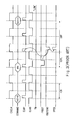
- the test mode signal TM has a high level
- the row active command RACT ⁇ 0> is inputted to maintain the row active state
- the write command WTA with the autoprecharge command is inputted to perform the write operation.
- the burst control signal/YBST is disabled from a low to high level, thereby finishing the write operation.
- the burst end signal YBSTEND is generated as a short pulse in correspondence with the rising edge of the inverted clock signal CLKB.
- the burst end signal YBSTEND is next transmitted to the precharge control unit 5 to output the precharge signal IPCG having a short pulse. Therefore, the semiconductor memory device performs the precharge operation according to the precharge signal IPCG.
- a clock frequency of a test circuit is increased by two times to perform the test.
- the write operation and the precharge operation are carried out in every one clock to reduce a test time.
- a parameter indicating a time from an input of data to input of the precharge command (data into precharge command; tDPL) is screened according to the test operation.
- the burst length BL is set up to be one (1), and the write command WTA with the autoprecharge command is transmitted to the respective unit memory cells in every two clocks.
- the test circuit using the above-described methods requires an operation frequency as high as an operation frequency of the semiconductor memory device, and also requires two clocks to perform the write and precharge operations in every unit memory cell.
- a test circuit in order to precisely screen the parameter tDPL, whenever the operation frequency of the semiconductor memory device is increased, a test circuit must be replaced by a test circuit using the corresponding frequency.
- the burst control signal/YBST is disabled from a low to high level, and the pulse of the burst end signal YBSTEND is generated in correspondence with the rising edge of the inverted clock signal CLKB.
- the precharge operation is performed by generating the pulse of the burst end signal YBSTEND, not in correspondence with the desired falling edge of the external clock signal EXCLK, but in correspondence with the succeeding falling edge thereof. As a result, the precharge operation is carried out in a time later than the wanted time by one clock.
- the conventional semiconductor memory device has disadvantages in that the parameter tDPL is not precisely screened and the test time is increased.
- an apparatus that reduces a test time and precisely tests a semiconductor memory device receiving a high frequency operation clock signal by using a test circuit operated synchronously with a low frequency operation clock signal, by generating a column burst signal which is a short pulse signal in correspondence with a rising edge of a column burst signal by using a pulse generator during a test operation.
- a semiconductor memory device having a state control unit that is configured to receive external control signals and output internal commands.
- a burst length control unit is provided and configured to receive the internal commands from the state control unit and output a burst control signal for maintaining an active state of a column operation for as long as a burst length according to the received internal commands.
- a clock buffer is further included and configured to receive an external clock signal and generate a pulse clock signal for generating a pulse in accordance with a rising edge of the external clock signal and an inverted clock signal having a phase opposite to a phase of the external clock signal.
- a burst control signal generating unit is configured to receive the burst control signal from the burst length control unit and, in turn, generate an inverted burst control signal having a phase opposite to a phase of the burst control signal and a test mode burst control signal having a short pulse occurring within a disabled time of the burst control signal. Also included is a burst end control unit that is controlled according to a test mode signal indicating the test mode.
- the burst end control unit is configured to generate a burst end signal indicating a burst end time by being synchronized with the inverted clock signal and using the inverted burst control signal during a normal operation and by being synchronized with the pulse clock signal and using the test mode burst control signal during a test operation.
- a precharge control unit is included and configured to perform a precharge operation according to the burst end signal.
- FIG. 1 illustrates a block diagram of a conventional semiconductor memory device.
- FIG. 2 is a detailed circuit diagram illustrating a burst end control unit in FIG. 1 .
- FIG. 3 is an operation timing diagram of a normal mode in FIG. 1 .
- FIG. 4 is an operation timing diagram of a test mode in FIG. 1 .
- FIG. 5 is an operation timing diagram in a state where a burst end signal is delayed by one clock in the test mode of FIG. 1 .
- FIG. 6 is a block diagram illustrating a semiconductor memory device in accordance with the present disclosed apparatus.
- FIG. 7 is a detailed circuit diagram illustrating a burst control signal generating unit in FIG. 6 .
- FIG. 8 is a detailed circuit diagram illustrating a burst end control unit in FIG. 6 .
- FIG. 9 is an operation timing diagram of a test mode in FIG. 6 .
- a semiconductor memory device includes a state control unit 10 , a clock buffer 20 , a burst length control unit 30 , a burst end control unit 40 , a precharge control unit 50 , and a burst control signal generating unit 60 .
- the state control unit 10 receives external control signals/CS, /RAS, /CAS and /WE and generates operation commands RACT, CACT and WTA.
- the clock buffer 20 receives an external clock signal EXCLK and generates a pulse clock signal CLKP having a short pulse in correspondence with a rising edge of the external clock signal EXCLK and an inverted clock signal CLKB having the opposite phase to the external clock signal EXCLK.
- Burst length control unit 30 outputs a burst control signal YBST for maintaining an active state of a column operation as long as a burst length BL according to the column active command CACT.
- the burst control signal generating unit 60 receives the burst control signal YBST from the burst length control unit 30 and generates an inverted burst control signal/YBST having the opposite phase to the burst control signal YBST and a test mode burst control signal YBSTM having a short pulse in a rising edge of the burst control signal YBST.
- the burst end control unit 40 detects an end point of the burst length BL and outputs a burst end signal YBSTEND notifying burst end, by using the inverted burst control signal/YBST in a normal mode and the test mode burst control signal YBSTM in a test mode. Finally, precharge control unit 50 generates a precharge signal IPCG for performing a precharge operation of the semiconductor memory device according to the burst end signal YBSTEND.
- FIG. 7 is a detailed circuit diagram illustrating the burst control signal generating unit 60 of the semiconductor memory device illustrated in FIG. 6 .
- the burst control signal generating unit 60 includes an inverter INV 11 for inverting the burst control signal YBST and outputting the inverted burst control signal/YBST, a delay unit 61 having an odd number of inverters INV 12 -INV 16 for delaying the burst control signal YBST for a predetermined time and a NAND gate ND 11 for NANDing the burst control signal YBST and the output signal from the delay unit 61 and outputting the test mode burst control signal YBSTM.
- FIG. 8 is a detailed circuit diagram illustrating the burst end control unit 40 of the semiconductor memory device illustrated in FIG. 6 .
- the burst end control unit 40 includes a comparing unit 70 enabled by test mode signal TM for driving the burst control signal/YBST according to the pulse clock signal CLKP in the normal mode, and driving the test mode burst control signal YBSTM according to the inverted clock signal CLKB in the test mode.
- the burst end control unit 40 also includes a burst end signal generating unit 80 for outputting the burst end signal YBSTEND according to an output signal COM from the comparing unit 70 .
- the comparing unit 70 includes transmission gates TG 11 and TG 12 for selectively transmitting the burst control signal/YBST and the test mode burst control signal YBSTM according to the test mode signal TM and an inverted signal/TM of the test mode signal TM by an inverter INV 17 .
- Transmission gates TG 13 and TG 14 are provided for selectively transmitting the pulse clock signal CLKP and the inverted clock signal CLKB according to the test mode signal TM and an inverted signal/TM of the test mode signal TM by an inverter INV 18 .
- a PMOS transistor PM 11 and an NMOS transistor NM 11 are included having their gates commonly connected to receive the signal selectively transmitted by the transmission gates TG 11 and TG 12 and their drains commonly connected.
- a source of the PMOS transistor PM 11 is connected to receive a power voltage VCC.
- An NMOS transistor NM 12 is included having its gate connected to receive the signal selectively transmitted by the transmission gates TG 13 and TG 14 , its drain connected to the source of the NMOS transistor NM 11 and its source connected to a ground voltage VSS.
- the burst end signal generating unit 80 includes a latch unit 81 having two inverters INV 19 and INV 20 for latching the output signal COM from the comparing unit 70 .
- a delay unit 82 is also included and comprises an even number of inverters INV 21 -INV 24 for delaying the output signal from the latch unit 81 for a predetermined time.
- a NOR gate NOR 11 is provided for NORing the output signal COM from the comparing unit 70 and the output signal from the delay unit 82 .
- An inverter INV 25 inverts the output signal from the NOR gate NOR 11 and outputs the burst end signal YBSTEND.
- an NMOS transistor NM 13 is included having its gate connected to receive a power up signal/PWR and resetting the output signal COM from the comparing unit 70 to the ground voltage VSS.
- a write operation is performed and the inverted burst control signal/YBST is disabled to a high level after the burst length BL. Since the test mode signal TM has a low level, a pulse of the burst end signal YBSTEND is generated in correspondence with a rising edge of the pulse clock signal CLKP after the inverted burst control signal/YBST is disabled. Finally, the precharge control unit 50 generates the precharge signal IPCG by using the burst end signal YBSTEND, thereby performing a precharge operation.
- the write operation is performed and the burst control signal generating unit 60 generates the test mode burst control signal YBSTM by using the burst control signal YBST.
- the burst control signal generating unit 60 generates the test mode burst control signal YBSTM such that it is a short pulse having a pulse width as long as a delay time of the delay unit 61 in the rising edge of the burst control signal YBST.
- the precharge control unit 50 After the pulse of the test mode burst control signal YBSTM is generated, the burst end signal YBSTEND is generated in correspondence with the rising edge of the inverted clock signal CLKB. Accordingly, the precharge control unit 50 generates the precharge signal IPCG to perform the precharge operation.
- the test mode burst control signal YBSTM is generated having the short pulse in correspondence with the rising edge of the burst control signal YBST and a precharge timing is controlled in the test mode, not by the burst control signal YBST, but by the test mode burst control signal YBSTM.
- a precharge timing is controlled in the test mode, not by the burst control signal YBST, but by the test mode burst control signal YBSTM.
- the semiconductor memory device to be tested is operated according to a high frequency clock signal
- the parameter can be precisely screened by using the test circuit operated according to a low frequency clock signal.
- the burst end signal for controlling the precharge operation in the test mode is generated according to the control signal having the short pulse in correspondence with the rising edge of the burst control signal to prevent delay of the test time due to a large pulse width of the burst control signal.
Landscapes
- Dram (AREA)
- For Increasing The Reliability Of Semiconductor Memories (AREA)
- Tests Of Electronic Circuits (AREA)
Applications Claiming Priority (2)
| Application Number | Priority Date | Filing Date | Title |
|---|---|---|---|
| KR10-2001-0082257A KR100414734B1 (ko) | 2001-12-21 | 2001-12-21 | 반도체 메모리 장치 |
| KR2001-82257 | 2001-12-21 |
Publications (2)
| Publication Number | Publication Date |
|---|---|
| US20030117882A1 US20030117882A1 (en) | 2003-06-26 |
| US6771558B2 true US6771558B2 (en) | 2004-08-03 |
Family
ID=19717373
Family Applications (1)
| Application Number | Title | Priority Date | Filing Date |
|---|---|---|---|
| US10/256,857 Expired - Fee Related US6771558B2 (en) | 2001-12-21 | 2002-09-27 | Semiconductor memory device |
Country Status (5)
| Country | Link |
|---|---|
| US (1) | US6771558B2 (de) |
| JP (1) | JP4224678B2 (de) |
| KR (1) | KR100414734B1 (de) |
| DE (1) | DE10249652A1 (de) |
| TW (1) | TW586119B (de) |
Cited By (8)
| Publication number | Priority date | Publication date | Assignee | Title |
|---|---|---|---|---|
| US20050251713A1 (en) * | 2004-05-06 | 2005-11-10 | Ihl-Ho Lee | Multi-port memory device having serial I/O interface |
| US20080002494A1 (en) * | 2006-06-29 | 2008-01-03 | Hynix Semiconductor Inc. | Auto-precharge signal generating circuit |
| US20080232182A1 (en) * | 2007-03-19 | 2008-09-25 | Hynix Semiconductor Inc. | Precharge voltage supplying circuit |
| US20090059700A1 (en) * | 2007-09-05 | 2009-03-05 | Hynix Semiconductor Inc. | Precharge control circuit in semiconductor memory apparatus |
| US20100085819A1 (en) * | 2008-10-06 | 2010-04-08 | Hynix Semiconductor Inc. | Burst length control circuit and semiconductor memory device using the same |
| US20100177590A1 (en) * | 2009-01-12 | 2010-07-15 | Hynix Semiconductor Inc. | Burst mode control circuit |
| US20110004794A1 (en) * | 2009-07-03 | 2011-01-06 | Jeong-Hun Lee | Semiconductor memory device |
| US10037793B2 (en) | 2016-06-28 | 2018-07-31 | SK Hynix Inc. | Semiconductor memory device and method for operating the same |
Families Citing this family (5)
| Publication number | Priority date | Publication date | Assignee | Title |
|---|---|---|---|---|
| KR100557948B1 (ko) * | 2003-06-20 | 2006-03-10 | 주식회사 하이닉스반도체 | 메모리 장치의 테스트 방법 |
| US6965534B2 (en) * | 2003-12-16 | 2005-11-15 | Infineon Technologies Ag | Random access memory using precharge timers in test mode |
| US20050134342A1 (en) * | 2003-12-18 | 2005-06-23 | Yung-Lung Lin | Circuit and method for generating a signal pulse |
| KR100792367B1 (ko) * | 2006-12-27 | 2008-01-09 | 주식회사 하이닉스반도체 | 반도체 메모리 장치 |
| KR100922880B1 (ko) * | 2008-06-05 | 2009-10-20 | 주식회사 하이닉스반도체 | 반도체 메모리소자의 오토프리차지 제어회로 및 방법 |
Citations (15)
| Publication number | Priority date | Publication date | Assignee | Title |
|---|---|---|---|---|
| JPS5963082A (ja) | 1982-09-30 | 1984-04-10 | Fujitsu Ltd | 仮想ペ−ジidによるアドレス空間のペ−ジ管理方式 |
| JPH01261925A (ja) | 1988-04-13 | 1989-10-18 | Fujitsu Ltd | 半導体集積回路 |
| JPH05101699A (ja) | 1991-10-03 | 1993-04-23 | Nec Ic Microcomput Syst Ltd | メモリ装置 |
| US5590082A (en) | 1994-06-07 | 1996-12-31 | Hitachi, Ltd. | Circuit and method for retaining DRAM content |
| US5748560A (en) | 1995-12-25 | 1998-05-05 | Mitsubishi Denki Kabushiki Kaisha | Synchronous semiconductor memory device with auto precharge operation easily controlled |
| US5805928A (en) | 1995-06-30 | 1998-09-08 | Hyundai Electronics Industries, Co., Ltd. | Burst length detection circuit for detecting a burst end time point and generating a burst mode signal without using a conventional burst length detection counter |
| JPH10289600A (ja) | 1997-04-14 | 1998-10-27 | Hitachi Ltd | 半導体記憶装置 |
| US5896404A (en) | 1997-04-04 | 1999-04-20 | International Business Machines Corporation | Programmable burst length DRAM |
| US5910923A (en) | 1997-10-23 | 1999-06-08 | Texas Instruments Incorporated | Memory access circuits for test time reduction |
| US6067273A (en) | 1998-02-27 | 2000-05-23 | Micron Technology, Inc. | Semiconductor memory burst length count determination detector |
| US6069829A (en) | 1998-09-29 | 2000-05-30 | Texas Instruments Incorporated | Internal clock multiplication for test time reduction |
| US6088291A (en) | 1997-06-03 | 2000-07-11 | Fujitsu Limited | Semiconductor memory device |
| US6108248A (en) * | 1996-04-04 | 2000-08-22 | Hyundai Electronics Industries Co., Ltd. | Column address strobe signal generator for synchronous dynamic random access memory |
| US6111807A (en) * | 1998-07-17 | 2000-08-29 | Mitsubishi Denki Kabushiki Kaisha | Synchronous semiconductor memory device allowing easy and fast text |
| US6246619B1 (en) | 2000-02-07 | 2001-06-12 | Vanguard International Semiconductor Corp. | Self-refresh test time reduction scheme |
Family Cites Families (6)
| Publication number | Priority date | Publication date | Assignee | Title |
|---|---|---|---|---|
| JPH0482098A (ja) * | 1990-07-23 | 1992-03-16 | Matsushita Electron Corp | Rom内蔵の集積回路装置 |
| KR19980037820A (ko) * | 1996-11-22 | 1998-08-05 | 김광호 | 반도체 메모리 장치 |
| JP3189745B2 (ja) * | 1997-06-27 | 2001-07-16 | 日本電気株式会社 | 同期式半導体記憶装置 |
| KR100308071B1 (ko) * | 1998-10-28 | 2001-10-19 | 박종섭 | 동기식 메모리 소자의 프리차지 장치 |
| KR100594206B1 (ko) * | 1999-11-05 | 2006-06-28 | 삼성전자주식회사 | 메모리를 구비하는 반도체장치의 메모리 테스트방법 |
| KR20010084291A (ko) * | 2000-02-24 | 2001-09-06 | 윤종용 | 반도체 메모리 장치 |
-
2001
- 2001-12-21 KR KR10-2001-0082257A patent/KR100414734B1/ko not_active IP Right Cessation
-
2002
- 2002-09-27 JP JP2002283223A patent/JP4224678B2/ja not_active Expired - Fee Related
- 2002-09-27 US US10/256,857 patent/US6771558B2/en not_active Expired - Fee Related
- 2002-10-01 TW TW091122632A patent/TW586119B/zh not_active IP Right Cessation
- 2002-10-24 DE DE10249652A patent/DE10249652A1/de not_active Withdrawn
Patent Citations (17)
| Publication number | Priority date | Publication date | Assignee | Title |
|---|---|---|---|---|
| JPS5963082A (ja) | 1982-09-30 | 1984-04-10 | Fujitsu Ltd | 仮想ペ−ジidによるアドレス空間のペ−ジ管理方式 |
| JPH01261925A (ja) | 1988-04-13 | 1989-10-18 | Fujitsu Ltd | 半導体集積回路 |
| JPH05101699A (ja) | 1991-10-03 | 1993-04-23 | Nec Ic Microcomput Syst Ltd | メモリ装置 |
| US5590082A (en) | 1994-06-07 | 1996-12-31 | Hitachi, Ltd. | Circuit and method for retaining DRAM content |
| US5805928A (en) | 1995-06-30 | 1998-09-08 | Hyundai Electronics Industries, Co., Ltd. | Burst length detection circuit for detecting a burst end time point and generating a burst mode signal without using a conventional burst length detection counter |
| US5748560A (en) | 1995-12-25 | 1998-05-05 | Mitsubishi Denki Kabushiki Kaisha | Synchronous semiconductor memory device with auto precharge operation easily controlled |
| US6108248A (en) * | 1996-04-04 | 2000-08-22 | Hyundai Electronics Industries Co., Ltd. | Column address strobe signal generator for synchronous dynamic random access memory |
| US5896404A (en) | 1997-04-04 | 1999-04-20 | International Business Machines Corporation | Programmable burst length DRAM |
| JPH10289600A (ja) | 1997-04-14 | 1998-10-27 | Hitachi Ltd | 半導体記憶装置 |
| US6088291A (en) | 1997-06-03 | 2000-07-11 | Fujitsu Limited | Semiconductor memory device |
| US6246620B1 (en) | 1997-06-03 | 2001-06-12 | Fujitsu Limited | Semiconductor memory device |
| US5910923A (en) | 1997-10-23 | 1999-06-08 | Texas Instruments Incorporated | Memory access circuits for test time reduction |
| US6067273A (en) | 1998-02-27 | 2000-05-23 | Micron Technology, Inc. | Semiconductor memory burst length count determination detector |
| US6229759B1 (en) | 1998-02-27 | 2001-05-08 | Micron Technology, Inc. | Semiconductor memory burst length count determination method |
| US6111807A (en) * | 1998-07-17 | 2000-08-29 | Mitsubishi Denki Kabushiki Kaisha | Synchronous semiconductor memory device allowing easy and fast text |
| US6069829A (en) | 1998-09-29 | 2000-05-30 | Texas Instruments Incorporated | Internal clock multiplication for test time reduction |
| US6246619B1 (en) | 2000-02-07 | 2001-06-12 | Vanguard International Semiconductor Corp. | Self-refresh test time reduction scheme |
Non-Patent Citations (1)
| Title |
|---|
| German Patent and Trademark Office Search Report dated May 2, 2003. |
Cited By (15)
| Publication number | Priority date | Publication date | Assignee | Title |
|---|---|---|---|---|
| US7089465B2 (en) * | 2004-05-06 | 2006-08-08 | Hynix Semiconductor Inc. | Multi-port memory device having serial I/O interface |
| US20050251713A1 (en) * | 2004-05-06 | 2005-11-10 | Ihl-Ho Lee | Multi-port memory device having serial I/O interface |
| US20080002494A1 (en) * | 2006-06-29 | 2008-01-03 | Hynix Semiconductor Inc. | Auto-precharge signal generating circuit |
| US7436719B2 (en) * | 2006-06-29 | 2008-10-14 | Hynix Semiconductor Inc. | Auto-precharge signal generating circuit |
| US20080232182A1 (en) * | 2007-03-19 | 2008-09-25 | Hynix Semiconductor Inc. | Precharge voltage supplying circuit |
| US7986577B2 (en) * | 2007-03-19 | 2011-07-26 | Hynix Semiconductor Inc. | Precharge voltage supplying circuit |
| US7768852B2 (en) * | 2007-09-05 | 2010-08-03 | Hynix Semiconductor Inc. | Precharge control circuit in semiconductor memory apparatus |
| US20090059700A1 (en) * | 2007-09-05 | 2009-03-05 | Hynix Semiconductor Inc. | Precharge control circuit in semiconductor memory apparatus |
| US20100085819A1 (en) * | 2008-10-06 | 2010-04-08 | Hynix Semiconductor Inc. | Burst length control circuit and semiconductor memory device using the same |
| US8014227B2 (en) * | 2008-10-06 | 2011-09-06 | Hynix Semiconductor Inc. | Burst length control circuit and semiconductor memory device using the same |
| US20100177590A1 (en) * | 2009-01-12 | 2010-07-15 | Hynix Semiconductor Inc. | Burst mode control circuit |
| US8027222B2 (en) * | 2009-01-12 | 2011-09-27 | Hynix Semiconductor Inc. | Burst mode control circuit |
| US20110004794A1 (en) * | 2009-07-03 | 2011-01-06 | Jeong-Hun Lee | Semiconductor memory device |
| US8386858B2 (en) * | 2009-07-03 | 2013-02-26 | Hynix Semiconductor Inc. | Semiconductor memory device |
| US10037793B2 (en) | 2016-06-28 | 2018-07-31 | SK Hynix Inc. | Semiconductor memory device and method for operating the same |
Also Published As
| Publication number | Publication date |
|---|---|
| JP4224678B2 (ja) | 2009-02-18 |
| TW586119B (en) | 2004-05-01 |
| DE10249652A1 (de) | 2003-07-03 |
| KR100414734B1 (ko) | 2004-01-13 |
| US20030117882A1 (en) | 2003-06-26 |
| KR20030052364A (ko) | 2003-06-27 |
| JP2003203498A (ja) | 2003-07-18 |
Similar Documents
| Publication | Publication Date | Title |
|---|---|---|
| US6385127B1 (en) | Synchronous semiconductor device and method for latching input signals | |
| KR100406543B1 (ko) | 동기식 메모리의 파이프 래치 제어회로 | |
| US8077529B2 (en) | Circuit and method for outputting data in semiconductor memory apparatus | |
| US6661735B2 (en) | Semiconductor memory device | |
| US7030671B2 (en) | Circuit for controlling pulse width | |
| US7230466B2 (en) | Data strobe signal generating circuit and data strobe signal generating method | |
| JP2006344367A (ja) | 同期式半導体メモリ装置のカラム選択ライン制御回路及びその制御方法 | |
| US6771558B2 (en) | Semiconductor memory device | |
| US20010017805A1 (en) | Automatic precharge apparatus of semiconductor memory device | |
| US6480033B2 (en) | Semiconductor device | |
| US20040022118A1 (en) | Semiconductor memory device and associated data read method | |
| US6992949B2 (en) | Method and circuit for controlling generation of column selection line signal | |
| US20050099837A1 (en) | Semiconductor memory device for controlling write recovery time | |
| US6819134B2 (en) | Decoding circuit for wafer burn-in test | |
| US7120083B2 (en) | Structure and method for transferring column address | |
| US20050174860A1 (en) | Apparatus and method for controlling enable time of signal controlling operation of data buses of memory device | |
| US6310823B1 (en) | Circuit for generating internal column strobe signal in synchronous semiconductor memory device | |
| US6678193B2 (en) | Apparatus and method for tracking between data and echo clock | |
| US7257726B2 (en) | Circuit for generating wait signal in semiconductor device | |
| US7263025B2 (en) | Semiconductor memory device for stably controlling power mode at high frequency and method of controlling power mode thereof | |
| JP4102535B2 (ja) | 半導体メモリ素子 | |
| KR20010065910A (ko) | 모드 레지스터 세팅장치 | |
| US7813190B2 (en) | Input circuit of semiconductor memory device ensuring enabled data input buffer during data input | |
| KR100652367B1 (ko) | Dll을 구비하는 반도체 메모리장치의 출력 핀을 통하여테스트 신호를 입력할 수 있는 클락 발생회로를 구비하는반도체 메모리장치 | |
| US7106653B2 (en) | Semiconductor memory device and data read method of the same |
Legal Events
| Date | Code | Title | Description |
|---|---|---|---|
| AS | Assignment |
Owner name: HYNIX SEMICONDUCTOR INC., KOREA, REPUBLIC OF Free format text: ASSIGNMENT OF ASSIGNORS INTEREST;ASSIGNOR:KIM, TAE YUN;REEL/FRAME:013530/0985 Effective date: 20020916 |
|
| FPAY | Fee payment |
Year of fee payment: 4 |
|
| FEPP | Fee payment procedure |
Free format text: PAYOR NUMBER ASSIGNED (ORIGINAL EVENT CODE: ASPN); ENTITY STATUS OF PATENT OWNER: LARGE ENTITY |
|
| FPAY | Fee payment |
Year of fee payment: 8 |
|
| REMI | Maintenance fee reminder mailed | ||
| LAPS | Lapse for failure to pay maintenance fees | ||
| STCH | Information on status: patent discontinuation |
Free format text: PATENT EXPIRED DUE TO NONPAYMENT OF MAINTENANCE FEES UNDER 37 CFR 1.362 |
|
| FP | Lapsed due to failure to pay maintenance fee |
Effective date: 20160803 |