US6707265B2 - Rotor angle detecting apparatus for DC brushless motors - Google Patents
Rotor angle detecting apparatus for DC brushless motors Download PDFInfo
- Publication number
- US6707265B2 US6707265B2 US10/075,245 US7524502A US6707265B2 US 6707265 B2 US6707265 B2 US 6707265B2 US 7524502 A US7524502 A US 7524502A US 6707265 B2 US6707265 B2 US 6707265B2
- Authority
- US
- United States
- Prior art keywords
- rotor angle
- reference value
- rotor
- value
- brushless motor
- Prior art date
- Legal status (The legal status is an assumption and is not a legal conclusion. Google has not performed a legal analysis and makes no representation as to the accuracy of the status listed.)
- Expired - Fee Related, expires
Links
Images
Classifications
-
- H—ELECTRICITY
- H02—GENERATION; CONVERSION OR DISTRIBUTION OF ELECTRIC POWER
- H02P—CONTROL OR REGULATION OF ELECTRIC MOTORS, ELECTRIC GENERATORS OR DYNAMO-ELECTRIC CONVERTERS; CONTROLLING TRANSFORMERS, REACTORS OR CHOKE COILS
- H02P6/00—Arrangements for controlling synchronous motors or other dynamo-electric motors using electronic commutation dependent on the rotor position; Electronic commutators therefor
- H02P6/14—Electronic commutators
- H02P6/16—Circuit arrangements for detecting position
- H02P6/18—Circuit arrangements for detecting position without separate position detecting elements
- H02P6/185—Circuit arrangements for detecting position without separate position detecting elements using inductance sensing, e.g. pulse excitation
-
- G—PHYSICS
- G01—MEASURING; TESTING
- G01D—MEASURING NOT SPECIALLY ADAPTED FOR A SPECIFIC VARIABLE; ARRANGEMENTS FOR MEASURING TWO OR MORE VARIABLES NOT COVERED IN A SINGLE OTHER SUBCLASS; TARIFF METERING APPARATUS; MEASURING OR TESTING NOT OTHERWISE PROVIDED FOR
- G01D5/00—Mechanical means for transferring the output of a sensing member; Means for converting the output of a sensing member to another variable where the form or nature of the sensing member does not constrain the means for converting; Transducers not specially adapted for a specific variable
- G01D5/12—Mechanical means for transferring the output of a sensing member; Means for converting the output of a sensing member to another variable where the form or nature of the sensing member does not constrain the means for converting; Transducers not specially adapted for a specific variable using electric or magnetic means
- G01D5/14—Mechanical means for transferring the output of a sensing member; Means for converting the output of a sensing member to another variable where the form or nature of the sensing member does not constrain the means for converting; Transducers not specially adapted for a specific variable using electric or magnetic means influencing the magnitude of a current or voltage
- G01D5/20—Mechanical means for transferring the output of a sensing member; Means for converting the output of a sensing member to another variable where the form or nature of the sensing member does not constrain the means for converting; Transducers not specially adapted for a specific variable using electric or magnetic means influencing the magnitude of a current or voltage by varying inductance, e.g. by a movable armature
- G01D5/2006—Mechanical means for transferring the output of a sensing member; Means for converting the output of a sensing member to another variable where the form or nature of the sensing member does not constrain the means for converting; Transducers not specially adapted for a specific variable using electric or magnetic means influencing the magnitude of a current or voltage by varying inductance, e.g. by a movable armature by influencing the self-induction of one or more coils
Definitions
- the present invention relates to a rotor angle detecting apparatus for detecting the rotor angle of a salient-pole DC brushless motor.
- the DC brushless motor In order to energize a DC brushless motor to obtain a desired torque, it is necessary to apply a voltage to the armatures in a suitable phase corresponding to the electric angle (hereinafter referred to as rotor angle) of the rotor which has magnetic poles. Therefore, the DC brushless motor generally has a position detecting sensor for detecting the rotor angle.
- the DC brushless motor with the position detecting sensor is required to have a circuit combined with the motor driver unit for receiving a detected signal which is outputted from the position detecting sensor, and wires between the position detecting sensor and the motor driver unit.
- the voltage applied to the armatures of the DC brushless motor is divided into voltages on two orthogonal axes, and when a high-frequency alternating voltage is applied to one axis, a current generated on the other axis in response to the application of the high-frequency alternating voltage is detected thereby to detect the rotor angle.
- this approach is disadvantageous in that it takes some time in an initial startup stage before the detected rotor angle reaches an actual rotor angle and it is difficult to correct the rotor angle.
- Another proposed technique uses a data table containing stored data representative of a correlation between rotor angles and armature currents when two- or three-phase currents are passed through the armatures of the DC brushless motor. Detected currents flowing through the armatures are applied to the data table, and approximating calculations are made on data in the data table to detect a rotor angle. Problems of this process are that errors tend to occur due to the effect of motor parameters that differ from motor to motor and the approximating calculations.
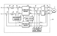
- a DC brushless motor 1 comprises a rotor 2 having field magnetic poles provided a permanent magnet and armatures 3 , 4 , 5 in three phases (U, V, W phases).
- armatures 3 , 4 , 5 in three phases (U, V, W phases).
- the rotor 2 is rotated by a revolving magnetic field which is produced as a combination of the magnetic fields generated by the armatures 3 , 4 , 5 .
- the revolving magnetic field needs to be generated in a direction depending on the angle ⁇ of the rotor 2 (in FIG. 1 ( a ), the angle of the rotor 2 as measured clockwise from the U-phase armature 3 , hereinafter referred to as “rotor angle ⁇ ”). Therefore, it is required to detect the rotor angle ⁇ for the control of the DC brushless motor.
- DC brushless motors generally have a position detecting sensor such as a resolver or the like for detecting the rotor angle ⁇ .
- a rotor angle detecting apparatus for a DC brushless motor according to the present invention is capable of detecting the rotor angle ⁇ without a position detecting sensor and hence dispenses with the need for a position detecting sensor.
- the magnetic reluctance of a gap between the rotor 2 and the armatures 2 , 3 , 4 varies periodically as the rotor 2 rotates.
- the magnetic reluctance varies in two cycles, i.e., when the rotor 2 makes one half of a revolution, the magnetic reluctance varies in one cycle.
- the magnetic reluctance is maximum when the rotor 2 is in a position ⁇ circumflex over ( 1 ) ⁇ and minimum when the rotor 2 is in a position ⁇ circumflex over ( 2 ) ⁇ .
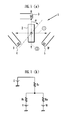
- FIG. 1 ( b ) The magnetic circuit of the DC brushless motor shown in FIG. 1 ( a ) is schematically shown in FIG. 1 ( b ) of the accompanying drawings. If it is assumed in FIG. 1 ( b ) that the magnetic reluctance varies in a unit cosine-wave pattern and the average value thereof in one periodic cycle is 0.5, then the magnetic reluctances Ru, Rv, Rw in the respective phases U, V, W are expressed by the following equations (1) through (3):
- Ru 1 ⁇ cos 2 ⁇ (1)
- Rv 1 - cos ⁇ ( 2 ⁇ ⁇ + 2 3 ⁇ ⁇ ) ( 2 )
- Rw 1 - cos ⁇ ( 2 ⁇ ⁇ - 2 3 ⁇ ⁇ ) ( 3 )
- the magnetic reluctance Rtu of the gap as seen from the U phase can be determined according to the following equation (4):
- VU, VV, VW represent respective voltages applied to the U-, V-, W-phase armatures
- Iu, Iv, Iw represent respective currents flowing through the U-, V-, W-phase armatures
- r represents the electric resistance of each of the U-, V-, W-phase armatures
- ⁇ m represents the electric angular velocity of the rotor 2
- Ke represents an induced voltage constant.
- K 1 2 ⁇ ( 1 - m ) ⁇ 1 - ⁇ 1 2 ⁇ ( 3 2 + 3 ⁇ cos ⁇ ⁇ 2 3 ⁇ ⁇ ) ( 11 )
- ⁇ represents the electric angular velocity of the high-frequency voltages vv, vu, vw.
- I ⁇ ⁇ u K ⁇ [ - ( 1 - m ) ⁇ cos ⁇ ⁇ ⁇ ⁇ ⁇ t - 3 ⁇ ⁇ 1 2 ⁇ cos ⁇ ( 2 ⁇ ⁇ - ⁇ ⁇ ⁇ t ) ] ( 15 )
- I ⁇ ⁇ w K ⁇ [ - ( 1 - m ) ⁇ cos ⁇ ⁇ ( ⁇ ⁇ ⁇ t + 2 3 ⁇ ⁇ ) - 3 ⁇ ⁇ 1 2 ⁇ cos ⁇ ( 2 ⁇ ⁇ - ⁇ ⁇ ⁇ t + 2 3 ⁇ ⁇ ) ] ( 16 )
- a rotor angle apparatus for a DC brushless motor comprising voltage applying means for applying drive voltages to three-phase armatures of a salient-pole DC brushless motor, high-frequency voltage imposing means for imposing high-frequency voltages to the drive voltages, respectively, first current detecting means for detecting a current flowing through a first-phase armature among the three-phase armatures, second current detecting means for detecting a current flowing through a second-phase armature among the three-phase armatures, reference value extracting means for extracting a sine reference value depending on a sine value which is twice the rotor angle of the DC brushless motor and a cosine reference value depending on a cosine value which is twice the rotor angle of the DC brushless motor, using a first current value detected by the first current detecting means and a second current value detected by the second current detecting means when the high-frequency voltages are imposed on
- the reference value extracting means can extract the sine reference value and the cosine reference value according to the equations (15), (16).
- the rotor angle calculating means can directly calculate the rotor angle of the DC brushless motor from the sine reference value and the cosine reference value which are extracted by the reference value extracting means.
- the rotor angle detecting apparatus according to the present invention has a better initial follow-up capability than conventional apparatus, and can detect the rotor angle accurately without being affected by the motor parameters.
- the reference value extracting means effects an integrating process or a low-pass filtering process on the high-frequency components to extract the sine reference value and the cosine reference value.
- the reference value extracting means can fix the high-frequency components which tend to vary with time and extract the sine reference value and the cosine reference value.
- the rotor angle calculating means calculates phase difference data representing a phase difference ( ⁇ circumflex over ( ⁇ ) ⁇ ) between an estimated value ( ⁇ circumflex over ( ⁇ ) ⁇ ) and an actual value ( ⁇ ) of the rotor angle of the DC brushless motor, using the sine reference value and the cosine reference value, and calculates the rotor angle according to follow-up calculations using an observer which is constructed to eliminate the phase difference ( ⁇ circumflex over ( ⁇ ) ⁇ ) represented by the phase difference data.
- the rotor angle calculating means can calculate the rotor angle from the sine reference value and the cosine reference value by using the observer.
- I ⁇ ⁇ u K ⁇ [ - ( 1 - m ) ⁇ cos ⁇ ⁇ ⁇ ⁇ ⁇ t - 3 ⁇ ⁇ 1 2 ⁇ cos ⁇ ( 2 ⁇ ⁇ - ⁇ ⁇ ⁇ t ) ] + I ⁇ ⁇ u ⁇ ⁇ d ⁇ ⁇ c ( 18 )
- Iudc the DC component of the current flowing through the U-phase armature.
- I ⁇ ⁇ w K ⁇ [ - ( 1 - m ) ⁇ cos ⁇ ⁇ ( ⁇ ⁇ ⁇ t + 2 3 ⁇ ⁇ ) - 3 ⁇ ⁇ 1 2 ⁇ cos ⁇ ( 2 ⁇ ⁇ - ⁇ ⁇ ⁇ t + 2 3 ⁇ ⁇ ) ] + I ⁇ ⁇ w ⁇ ⁇ d ⁇ ⁇ c ( 19 )
- Iwdc the DC component of the current flowing through the W-phase armature.
- the reference value extracting means can calculate the sine reference value and the cosine reference value by calculating the equations (21), (22) as the integrating process.
- the tan ⁇ 1 function varies greatly as the sine reference value (Vs) and the cosine reference value (Vc) vary. Therefore, when the rotor angle of the DC brushless motor is calculated according to the equation (23), a detecting error of the rotor angle may increase due to a calculating error of the sine reference value (Vs) and the cosine reference value (Vc).
- the rotor angle calculating means generates phase difference data representing a phase difference ( ⁇ circumflex over ( ⁇ ) ⁇ ) between an estimated value ( ⁇ circumflex over ( ⁇ ) ⁇ ) and an actual value ( ⁇ ) of the rotor angle of the DC brushless motor according to the following equation (24) while the high-frequency voltages are imposed on the drive voltages by the high-frequency voltage imposing means and the sine reference value and the cosine reference value are extracted by the reference value extracting means in each control cycle, calculates the rotor angle of the DC brushless motor according to the above equation (23) in a first control cycle, and, in next and following control cycles, uses the rotor angle of the DC brushless motor calculated in a preceding control cycle as an estimated value ( ⁇ circumflex over ( ⁇ ) ⁇ ) for the rotor angle of the DC brushless motor in the preceding control cycle, updates the estimated value ( ⁇ circumflex over ( ⁇ ) ⁇ ) for the rotor angle of the DC brushless motor with an observer which sequentially updates
- V ⁇ ⁇ s ⁇ cos ⁇ ⁇ 2 ⁇ ⁇ ⁇ - V ⁇ ⁇ c ⁇ sin ⁇ ⁇ 2 ⁇ ⁇ ⁇ ⁇ V ⁇ ⁇ s 2 - V ⁇ ⁇ c 2 ⁇ sin ⁇ ( 2 ⁇ ⁇ - 2 ⁇ ⁇ ⁇ ) ⁇ ⁇ V ⁇ ⁇ s 2 - V ⁇ ⁇ c 2 ⁇ 2 ⁇ ( ⁇ - ⁇ ⁇ ) ⁇ ( in ⁇ ⁇ c ⁇ ⁇ a ⁇ ⁇ s ⁇ ⁇ e ⁇ ⁇ ⁇ - ⁇ ⁇ 0 ) ( 24 )
- the rotor angle calculating means calculates the rotor angle of the DC brushless motor according to the equation (23) only in the first control cycle.
- the rotor angle calculating means applies the phase difference data generated based on the equation (24) in the preceding control cycle and the rotor angle of the DC brushless motor calculated in the preceding control cycle to the observer, and calculates an estimated value ( ⁇ circumflex over ( ⁇ ) ⁇ ) for the rotor angle of the DC brushless motor in the preceding control cycle.
- the rotor angle calculating means can thus detect accurately the rotor angle of the DC brushless motor in the next and following control cycles.
- the rotor angle calculating means uses, as the phase difference data, ⁇ 1 produced by dividing the phase difference by ⁇ square root over (Vs 2 +Vc 2 ) ⁇ according to the following equation (25) thereby to prevent the gain of the observer from varying depending on changes in the magnitudes of the sine reference value Vs and the cosine reference value Vc. Therefore, the rotor angle of the DC brushless motor can stably be detected.
- a bottom value of the output torque of the DC brushless motor in a high current range i.e., a lower end value of the varying range of the output torque, may be lowered, tending to increase the pulsation of the output torque.
- the inventors of the present invention have made various studies in order to suppress such a reduction in the bottom value of the output torque, and have found as a result that the bottom value of the output torque can be increased by forcibly shifting the rotor angle of the DC brushless motor calculated by the rotor angle calculating means to change the phase difference between the detected and actual values of the rotor angle.
- the rotor angle calculating means can construct the observer using ⁇ 2 calculated according to the following equation (27) with an offset value (offset) added thereto as the phase difference data, for thereby calculating the rotor angle of the DC brushless motor to equalize the difference between the detected and actual values of the rotor angle to the offset value.
- phase difference between the detected and actual values of the rotor angle is forcibly shifted to suppress a reduction in the bottom value of the output torque for thereby reducing the pulsation of the output torque:
- the inductance of the rotor of the DC brushless motor varies in periodic cycles each having an electric angle of 180°. If the rotor angle of the DC brushless motor is detected by imposing the high-frequency voltages to the drive voltages of the DC brushless motor with the high-frequency voltage imposing means, then the direction of the magnetic poles of the rotor magnet of the DC brushless motor cannot be determined. That is, the rotor angle ⁇ (0 ⁇ 180°) and the rotor angle ⁇ +180° cannot be detected separately from each other.
- the inventors have made various studies and found that if the DC brushless motor is controlled according to a dq conversion process which handles the DC brushless motor as an equivalent circuit having a q-axis armature disposed on a q-axis extending in the direction of magnetic fluxes of field magnetic poles of the rotor of the DC brushless motor and a d-axis armature disposed on a d-axis extending perpendicularly to the q-axis, then when a current is passed through the q-axis armature and the rotor angle of the rotor is detected by the rotor angle calculating means, the sine reference value and the cosine reference value depending on the calculated rotor angle differ when the direction of the magnetic field generated by q-axis armature and the direction of the magnetic field generated by the magnetic poles of the rotor are the same as each other and when these directions are different from each other.
- the rotor angle detecting apparatus further includes correlation data storage means for handling the DC brushless motor as an equivalent circuit having a q-axis armature disposed on a q-axis extending in the direction of magnetic fluxes of field magnetic poles of the rotor of the DC brushless motor and a d-axis armature disposed on a d-axis extending perpendicularly to the q-axis, and storing, in advance, data of a map or a relational equation representing a correlation between a rotor angle of the DC brushless motor which is calculated by the rotor angle calculating means while a predetermined magnetic pole determining current is passed through the q-axis armature, and a threshold established between a saturated reference value which is calculated by a predetermined calculating process depending on the sine reference value and the cosine reference value which are extracted by the reference value extracting means when the rotor is in a saturated state in which the direction of a magnetic field generated by the q-
- the rotor angle detecting apparatus also has magnetic pole direction determining means for handling the DC brushless motor as the equivalent circuit, and comparing a threshold value depending on the rotor angle which is obtained when the rotor angle calculated by the rotor angle calculating means while the magnetic pole determining current is passed through the q-axis armature is applied to the map or the relational equation, with a magnetic pole determining value calculated according to the predetermined calculating process depending on the sine reference value and the cosine reference value which are extracted by the reference value extracting means when the rotor angle is calculated, thereby to determine whether the rotor is in the saturated state or the unsaturated state for determining the direction of the magnetic poles of the rotor.
- the magnetic pole direction determining means detects the rotor angle of the DC brushless motor while the magnetic pole determining current is passed through the q-axis armature.
- the magnetic pole direction determining means compares a threshold value obtained by applying the calculated rotor angle to the map/relational equation with a magnetic pole determining value calculated according to the predetermined calculating process depending on the sine reference value and the cosine reference value which are extracted by the reference value extracting means when the rotor angle is calculated, thereby to determine the direction of the magnetic poles of the rotor.
- the rotor angle of the DC brushless motor can be detected in a range from 0 to 360°.
- FIGS. 1 ( a ) and 1 ( b ) are views schematically showing a structure of a DC brushless motor
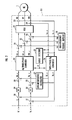
- FIG. 2 is a block diagram of a motor controller for controlling operation of the DC brushless motor shown in FIGS. 1 ( a ) and 1 ( b );
- FIGS. 3 ( a ) and 3 ( b ) are graphs illustrative of a process of determining the direction of magnetic poles of the rotor of the DC brushless motor.
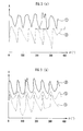
- FIGS. 4 ( a ) and 4 ( b ) are graphs illustrative of a process of suppressing a reduction in the bottom value of the output torque of the DC brushless motor.
- a rotor angle detecting apparatus will be described in detail below with reference to FIGS. 1 ( a ), 1 ( b ) through 4 ( a ), 4 ( b ).
- a motor controller 10 shown in FIG. 2 controls currents flowing through the armatures 3 , 4 , 5 of the salient-pole DC brushless motor 1 (hereinafter referred to as “motor 1”) shown in FIGS. 1 ( a ) and 1 ( b ) through a feedback loop.
- the motor controller 10 handles the motor 1 as an equivalent circuit according to a dq coordinate system which has a q-axis armature disposed on a q-axis extending in the direction of magnetic fluxes of field magnetic poles of the rotor 2 and a d-axis armature disposed on a d-axis extending perpendicularly to the q-axis.
- the motor controller 10 controls the voltages applied to the three-phase armatures of the motor 1 to bring a command value Id_c for the current flowing through the d-axis armature (hereinafter referred to as “d-axis current”) and a command value Iq_c for the current flowing through the q-axis armature (hereinafter referred to as “q-axis current”), which command values are given from an external source, into conformity with a detected value Id_s of the d-axis current and a detected value Iq_s of the q-axis current, respectively, which have been calculated by way of three-phase/dq conversion from detected values of the currents that actually flow through the three-phase armatures of the motor 1 .
- the motor controller 10 comprises a dq/three-phase converter 20 for converting a command value Vd_c for the voltage applied to the d-axis armature (hereinafter referred to as “d-axis voltage”) and a command value Vq_c for the voltage applied to the q-axis armature (hereinafter referred to as “q-axis voltage”) into command values VU_c, VV_c, VW_c for the voltages applied to the U-, V-, W-phase armatures of the motor 1 , a high-frequency voltage imposer 21 (corresponding to a high-frequency voltage imposing means according to the present invention) for imposing high-frequency voltages vu, vv, vw respectively on the command values VU_c, VV_c, VW_c outputted from the dq/three-phase converter 20 , and a power drive unit (PDU) 22 (corresponding to a voltage applying means according to the present invention) for applying voltages VU, VV, VW depending on the command values
- the motor controller 10 also has a U-phase current sensor 23 (corresponding to a first current detecting means according to the present invention) for detecting a current flowing through the armature of the U phase (corresponding to a first phase) of the motor 1 , a W-phase current sensor 24 (corresponding to a second current detecting means according to the present invention) for detecting a current flowing through the armature of the W phase (corresponding to a second phase) of the motor 1 , an angle detector 25 for detecting the rotor angle ⁇ using a detected current value IU_s from the U-phase current sensor 23 and a detected current value IW_s from the W-phase current sensor 24 , a three-phase/dq converter 26 for calculating the detected values Id_s, Iq_s using the detected current values IU_s, IW_s, and a non-interference calculator 27 for canceling out the effect of speed electromotive forces that interfere with each other between the d-axis and the q-axis.
- a first subtractor 28 subtracts the detected value Id_s from the command value Id_c for the d-axis current
- a first PI processor 29 performs a PI (Proportional plus Integral) process on the difference between the detected value Id_s and the command value Id_c.
- a first adder 30 adds a non-interference component to an output signal from the first PI processor 29 , generating the command value Vd_c for the d-axis voltage depending on the difference between the detected value Id_s and the command value Id_c.
- a second subtractor 31 subtracts the detected value Iq s from the command value Iq_c for the q-axis current
- a second PI processor 32 performs a PI process on the difference between the detected value Iq_s and the command value Iq_c.
- a second adder 33 adds a non-interference component to an output signal from the second PI processor 32 , generating the command value Vq_c for the q-axis voltage depending on the difference between the detected value Iq s and the command value Iq_c.
- the command value Vd_c for the d-axis voltage and the command value Vq_c for the q-axis voltage are supplied to the dq/three-phase converter 20 .
- the power drive unit 22 Based on the command values VU_c, VV_c, VW_c with the high-frequency voltages vu, vv, vw imposed thereon, supplied from the dq/three-phase converter 20 , the power drive unit 22 applies the three-phase voltages VU, VV, VW to the armatures of the motor 1 to control the currents flowing through the armatures in order to eliminate the difference between the detected value Id_s and the command value Id_c and the difference between the detected value Iq_s and the command value Iq_c.
- the motor controller 10 detects the rotor angle ⁇ by imposing the high-frequency voltages vu, vv, vw (see the equation (12)) from the high-frequency voltage imposer 21 respectively on the command values VU_c, VV_c, VW_c for the voltages applied to the U-, V-, W-phases which are out-putted from the dq/three-phase converter 20 , without using a position detecting sensor such as a resolver or the like.
- a third adder 34 adds the high-frequency voltage vu to the command value VU_c
- a fourth adder 35 adds the high-frequency voltage vv to the command value VV_c
- a fifth adder 36 adds the high-frequency voltage vw to the command value VW_c.
- the angle detector 25 detects the rotor angle ⁇ from the detected current value IU_s from the U-phase current sensor 23 and the detected current value IW_s from the W-phase current sensor 24 at the time the high-frequency voltages vu, vv, vw are imposed on the command values VU_c, VV_c, VW_c.
- the angle detector 25 has the functions of a reference value extracting means, a rotor angle calculating means, and a magnetic pole direction determining means according to the present invention.
- the angle detector 25 , the power drive unit 22 , the high-frequency voltage imposer 21 , the U-phase current sensor 23 , and the W-phase current sensor 24 jointly make up the apparatus for detecting the rotor angle of a DC brushless motor according to the present invention.
- a process of detecting the rotor angle ⁇ with the high-frequency voltage imposer 21 and the angle detector 25 will be described below.
- the angle detector 25 puts the detected current value IU_s from the U-phase current sensor 23 and the detected current value IW_s from the W-phase current sensor 24 respectively in Iu, Iw in the above equations (21), (22), and puts the angular velocity X of the high-frequency voltages vu, vv, vw imposed by the high-frequency voltage imposer 21 in ⁇ in the equations (21), (22), thereby calculating a sine reference value Vs and a cosine reference value Vc which are twice the rotor angle ⁇ .
- the sine and cosine components of ⁇ in the equations (21), (22) correspond to high-frequency components of the imposed high-frequency voltages according to the present invention.
- the rotor angle ⁇ can be calculated in an electric angle range from 0 to 180° or from 180° to 360° for the salient-pole DC brushless motor. In order to detect the rotor angle ⁇ in an electric angle range from 0 to 360°, therefore, it is necessary to perform a process of determining the direction of the magnetic poles of the rotor 2 .
- ⁇ 1 (a variation in the DC component 1 of the self-inductance of each the phases U, V, W) is increased at the time the rotor 2 is in a saturated state where the direction of the magnetic field generated by the currents and the direction of the magnetic field generated by the magnet are the same as each other.
- ⁇ 1 is reduced at the time the rotor 2 is in an unsaturated state where the direction of the magnetic field generated by the currents and the direction of the magnetic field generated by the magnet are opposite to each other.
- a magnetic pole determining value A which is calculated from the sine reference value Vs and the cosine reference value Vc (calculated by the equations (21), (22)) which vary depending on the value of Al according to the following equation (40) (corresponding to a calculating process according to the present invention) differs when the rotor 2 is in the saturated state and when the rotor 2 is in the unsaturated state:
- the angle detector 25 can detect whether the rotor 2 is in the saturated state or the unsaturated state to determine the direction of the magnetic poles of the rotor 2 by calculating the sine reference value Vs and the cosine reference value Vc according to the equations (21), (22) from the detected current values from the W-phase current sensor 24 and the U-phase current sensor 23 while the high-frequency voltages vu, vv, vw are imposed by the high-frequency voltage imposer 21 and a predetermined magnetic pole determining current is passed through the q-axis armature, and comparing the magnetic pole determining value A calculated from the sine reference value Vs and the cosine reference value Vc according to the equation (33) with a predetermined threshold.
- the magnetic pole determining value A may differ when the rotor 2 is in the saturated state and when the rotor 2 is in the unsaturated state. In such a case, the direction of the magnetic poles of the rotor 2 cannot be determined simply by comparing the magnetic pole determining value A with the predetermined threshold.
- FIG. 3 ( a ) is a graph which shows how the magnetic pole determining value A varies with respect to the actual angle values of the rotor 2 .
- the graph shown in FIG. 3 ( a ) has a horizontal axis representing actual values of the rotor angle ⁇ and a vertical axis representing the magnetic pole determining value A.
- a curve ⁇ circle around ( 1 ) ⁇ indicates the transition of the magnetic pole determining value A when the rotor 2 is in the saturated state
- a curve ⁇ circle around ( 2 ) ⁇ indicates the transition of the magnetic pole determining value A when the rotor 2 is in the unsaturated state.
- a constant threshold B is used to determine the direction of the magnetic poles of the rotor 2 as shown in FIG. 3 ( a ), then since there are certain angles where the rotor 2 is judged as being saturated on both the curves ⁇ circle around ( 1 ) ⁇ , ⁇ circle around ( 2 ) ⁇ , the direction of the magnetic poles of the rotor 2 cannot not be determined from the magnetic pole determining value A.
- the angle detector 25 determines the direction of the magnetic poles of the rotor 2 as follows:
- FIG. 3 ( b ) is a graph which shows how the magnetic pole determining value A varies with respect to the angle values detected by the angle detector 25 .
- the graph shown in FIG. 3 ( b ) has a horizontal axis representing detected values of the rotor angle ⁇ and a vertical axis representing the magnetic pole determining value A.
- a curve ⁇ circle around ( 3 ) ⁇ indicates the transition of the magnetic pole determining value A when the rotor 2 is in the saturated state
- a curve indicates the transition of the magnetic pole determining value A when the rotor 2 is in the unsaturated state.
- the curves ⁇ circle around ( 3 ) ⁇ , ⁇ circle around ( 4 ) ⁇ vary differently with respect to the detected values of the rotor angle ⁇ .
- a threshold whose value varies depending on the rotor angle ⁇ as indicated by a curve ⁇ circle around ( 5 ) ⁇ is established between the curves ⁇ circle around ( 3 ) ⁇ , ⁇ circle around ( 4 ) ⁇ .
- the angle detector 25 can now determine the direction of the magnetic poles of the rotor 2 by comparing the detected values of the rotor angle ⁇ and the threshold represented by the curve ⁇ circle around ( 5 ) ⁇ .
- the threshold varies in a sine-wave pattern which period is the same as the curves ⁇ circle around ( 3 ) ⁇ , ⁇ circle around ( 4 ) ⁇ .
- a data map representing a correlation between rotor angles and threshold values corresponding to those rotor angles is stored in a memory.
- the angle detector 25 detects a rotor angle ⁇ while the high-frequency voltages vu, vv, vw are imposed on the drive voltages VU, VV, VW of the motor 1 and a predetermined magnetic pole determining current is passed through the q-axis armature, and applies the detected rotor angle ⁇ to the correlation data of the data map, thereby obtaining a threshold value corresponding to the detected rotor angle ⁇ .
- the angle detector 25 calculates a magnetic pole determining value A according to the equation (33) from the sine reference value Vs and the cosine reference value Vc calculated when the rotor angle ⁇ is detected, and compares the magnetic pole determining value A with the threshold value corresponding to the detected rotor angle ⁇ . If the magnetic pole determining value A is greater than the threshold value, then the rotor 2 is judged as being in the saturated state, and if the magnetic pole determining value A is smaller than the threshold value, then the rotor 2 is judged as being in the unsaturated state. As a result, the angle detector 25 can determine the direction of the magnetic poles of the rotor 2 .
- the correlation between rotor angles and threshold values corresponding to those rotor angles may be represented by an equation, rather than a data map, and the data of the equation may be stored in a memory.
- a rotor angle ⁇ detected by the angle detector 25 may be applied to the equation, thereby obtaining a threshold value corresponding to the detected rotor angle ⁇ .
- the angle detector 25 calculates a sine reference value Vs and a cosine reference value Vc which are twice the rotor angle ⁇ by integrating high-frequency components that vary with time according to the equations (21), (22).
- the angle detector 25 may effect low-pass filtering on high-frequency components to output a sine reference value and a cosine reference value.
- an estimated angle ⁇ circumflex over ( ⁇ ) ⁇ of the rotor angle ⁇ if the difference between the rotor angle ⁇ and the estimated angle ⁇ circumflex over ( ⁇ ) ⁇ is substantially zero, then these angles are related to each other according to the equation (34) given below.
- estimated angle ⁇ circumflex over ( ⁇ ) ⁇ , the sine reference value Vs, and the cosine reference value Vc an approximate value of the phase difference between the estimated angle ⁇ circumflex over ( ⁇ ) ⁇ and the actual angle ⁇ can be determined, and the actual angle ⁇ can be calculated from the approximate value of the phase difference.
- V ⁇ ⁇ s ⁇ cos ⁇ ⁇ 2 ⁇ ⁇ ⁇ - V ⁇ ⁇ c ⁇ sin ⁇ ⁇ 2 ⁇ ⁇ ⁇ ⁇ K ⁇ 3 ⁇ 3 ⁇ ⁇ 1 4 ⁇ ⁇ ⁇ sin ⁇ ( 2 ⁇ ⁇ - 2 ⁇ ⁇ ⁇ ) ⁇ ⁇ K ⁇ ⁇ ( ⁇ - ⁇ ⁇ ) ( 34 )
- ⁇ (n) and ⁇ m (n) represent a rotor angle ⁇ and a angular velocity ⁇ m , respectively, at a certain sampling time n
- ⁇ (n+1) and ⁇ m (n+1) represent a rotor angle ⁇ and a angular velocity ⁇ m , respectively, at a sampling time n+1 following the sampling time n.
- the absolute value of the inherent value ⁇ which is calculated according to the equation (39) must be 1 or less.
- ⁇ n according to the following equation (40) is calculated using phase difference data depending on the phase difference ( ⁇ circumflex over ( ⁇ ) ⁇ ) between the estimated angle ⁇ circumflex over ( ⁇ ) ⁇ and the actual value ⁇ of the rotor angle according to the equation (24), and the rotor angle ⁇ is calculated by an observer expressed by the following equation (41) which is arranged to eliminate the phase difference ( ⁇ circumflex over ( ⁇ ) ⁇ ), then the gain varies as the magnitude of the high-frequency components ( ⁇ square root over (Vs 2 +Vc 2 ) ⁇ ) varies, and the stability is possibly impaired.
- K1, K2 represent calculating gains.
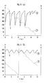
- a rotor angle ⁇ is calculated by an observer constructed using the phase difference data ⁇ 1 calculated according to the equation (25) or (26) and the drive voltages VU, VV, VW applied to the motor 1 are controlled based on the rotor angle ⁇ , then a bottom value D of the output torque of the motor 1 , i.e., a lower end value of the varying range of the output torque, is lowered, tending to increase the pulsation of the output torque.
- FIG. 4 ( a ) is a graph showing the manner in which the bottom value D of the output torque of the motor 1 is lowered.
- the graph shown in FIG. 4 ( a ) has a horizontal axis representing time (t), a right vertical axis representing the output torque (Tr) of the motor 1 , and a left vertical axis representing the rotor angle ( ⁇ ).
- a curve ⁇ circle around ( 6 ) ⁇ represents the time-dependent transition of the output torque of the motor 1
- a curve ⁇ circle around (7) ⁇ represents the time-dependent transition of the detected value of the rotor angle.
- the angle detector 25 detects a rotor angle with an observer constructed using phase difference data ⁇ 2 calculated according to the equation (27) with an offset value (offset) added thereto, thus forcibly shifting the detected value of the rotor angle for thereby reducing the detecting error of the rotor angle.
- FIG. 4 ( b ) is a graph showing the time-dependent transition of the output torque of the motor 1 at the time the drive voltages VU, VV, VW of the motor 1 is controlled based on the rotor angle which is calculated by the observer constructed using the phase difference data ⁇ 2 that is calculated with the offset value (offset) added thereto.
- the graph shown in FIG. 4 ( b ) has a horizontal axis representing time (t), a right vertical axis representing the output torque (Tr) of the motor 1 , and a left vertical axis representing the rotor angle ( ⁇ ).
- a curve ⁇ circle around (8) ⁇ represents the time-dependent transition of the output torque of the motor 1
- a curve ⁇ circle around ( 9 ) ⁇ represents detected values of the rotor angle.
- the gain slightly varies when the parameters of the motor 1 vary. However, the gain variations do not cause problems to the estimation of the rotor angle ⁇ if they are in a range not affecting the stability of the observer.
- the sine reference value Vs is calculated by the equation (21), and the cosine reference value Vc is calculated by the equation (22).
- the equations (42), (43) multiply a term not relating to the rotor angle ⁇ and an orthogonal time function and integrates the product. While the equations (42), (43) can determine the sine reference value Vs, they are unable to calculate the cosine reference value Vc. However, with the cosine reference value Vc calculated by the following equation (44), a rotor angle can be detected by follow-up calculations of the observer according to the equations (23), (36).
- the first and second phases may be another combination of phases of the motor 1 .
- the power drive unit 22 controls the voltages applied to the armatures of the motor 1 by way of PWM, PWM carriers in the phases U, V, W which are usually in phase with each other can be given at 120°-apart different angles for detecting the rotor angle ⁇ using high-frequency components contained in the PWM carriers.
- the power drive unit 22 performs the function of the high-frequency voltage imposing means, and hence the high-frequency voltage imposer 21 is dispensed with.
Landscapes
- Engineering & Computer Science (AREA)
- Power Engineering (AREA)
- Control Of Motors That Do Not Use Commutators (AREA)
- Control Of Ac Motors In General (AREA)
Applications Claiming Priority (5)
| Application Number | Priority Date | Filing Date | Title |
|---|---|---|---|
| JP2001-40446 | 2001-02-16 | ||
| JP2001-040446 | 2001-02-16 | ||
| JP2001040446 | 2001-02-16 | ||
| JP2001-288303 | 2001-09-21 | ||
| JP2001288303A JP3529752B2 (ja) | 2001-02-16 | 2001-09-21 | Dcブラシレスモータのロータ角度検出装置 |
Publications (2)
| Publication Number | Publication Date |
|---|---|
| US20020149335A1 US20020149335A1 (en) | 2002-10-17 |
| US6707265B2 true US6707265B2 (en) | 2004-03-16 |
Family
ID=26609557
Family Applications (1)
| Application Number | Title | Priority Date | Filing Date |
|---|---|---|---|
| US10/075,245 Expired - Fee Related US6707265B2 (en) | 2001-02-16 | 2002-02-15 | Rotor angle detecting apparatus for DC brushless motors |
Country Status (4)
| Country | Link |
|---|---|
| US (1) | US6707265B2 (fr) |
| JP (1) | JP3529752B2 (fr) |
| CA (1) | CA2372266C (fr) |
| DE (1) | DE10206410B4 (fr) |
Cited By (25)
| Publication number | Priority date | Publication date | Assignee | Title |
|---|---|---|---|---|
| US20030011347A1 (en) * | 2000-02-09 | 2003-01-16 | Martin Kaplan | Method for operating a switched reluctance electrical generator |
| US20040061461A1 (en) * | 2002-10-01 | 2004-04-01 | Honda Giken Kogyo Kabushiki Kaisha | Apparatus for controlling permanent-magnet rotary machine |
| US20040066205A1 (en) * | 2002-09-26 | 2004-04-08 | Honda Giken Kogyo Kabushiki Kaisha | Rotor angle detecting apparatus for DC brushless motor |
| US20040232862A1 (en) * | 2001-08-06 | 2004-11-25 | Wogari Mengesha Mamo | Electric motor pole position sensing method, pole position sensing apparatus, and electric motor control apparatus using the same |
| US20040251860A1 (en) * | 2003-01-09 | 2004-12-16 | Mehrdad Ehsani | Advanced sensorless drive technique for brushless DC motors |
| US20050029972A1 (en) * | 2003-05-19 | 2005-02-10 | Nobuyuki Imai | Control apparatus for brushless DC motor |
| US20050077864A1 (en) * | 2002-10-15 | 2005-04-14 | National Kaohsiung Univerity Of Applied Sciences | Control method and system for motor |
| US20060038517A1 (en) * | 2004-08-23 | 2006-02-23 | Agile Systems Inc. | System and method for sensor less magnetic field control of a motor |
| US20060082335A1 (en) * | 2004-10-19 | 2006-04-20 | Honda Motor Co., Ltd. | Method for detecting rotor angle of DC brushless motor and controller of DC brushless motor |
| US20060113941A1 (en) * | 2004-11-30 | 2006-06-01 | Del Castillo Patrick D | Brushless DC motor controller |
| US20070035269A1 (en) * | 2005-08-11 | 2007-02-15 | Kazuaki Tobari | Vector controller for permanent magnet synchronous motor |
| US20070069668A1 (en) * | 2005-09-29 | 2007-03-29 | Mackay David K | System and method for evaluating back electromotive force in a motor |
| US20070069676A1 (en) * | 2005-09-29 | 2007-03-29 | Mackay David K | System and method for commutating a motor |
| US20070069677A1 (en) * | 2005-09-29 | 2007-03-29 | Mackay David K | System and method for applying energy to a motor |
| US20070069669A1 (en) * | 2005-09-29 | 2007-03-29 | Mackay David K | System and method for starting and operating a motor |
| US20070069675A1 (en) * | 2005-09-29 | 2007-03-29 | Mackay David K | System and method for attenuating noise associated with a back electromotive force signal in a motor |
| US20070164691A1 (en) * | 2005-09-29 | 2007-07-19 | Agile Systems Inc. | System and method for attenuating noise associated with a back electromotive force signal in a motor |
| US20070216342A1 (en) * | 2006-03-15 | 2007-09-20 | Kazuaki Tobari | Vector Control Apparatus for Permanent Magnet Motor |
| US20070252551A1 (en) * | 2004-02-05 | 2007-11-01 | Dyson Technology Limited | Control of Electrical Machines |
| US7299708B2 (en) * | 2001-11-12 | 2007-11-27 | International Rectifier Corporation | Rotor angle estimation for permanent magnet synchronous motor drive |
| US20090267547A1 (en) * | 2007-03-28 | 2009-10-29 | Kabushiki Kaisha Yaskawa Denki | Motor control device and magnetic pole position estimation precision confirming method |
| US9300234B2 (en) * | 2014-01-17 | 2016-03-29 | Kabushiki Kaisha Yaskawa Denki | Rotary electric machine controller, rotary electric machine control method, and method of creating control map |
| US20170179867A1 (en) * | 2015-12-22 | 2017-06-22 | Okuma Corporation | Motor control device |
| US9989384B2 (en) | 2011-06-15 | 2018-06-05 | Trw Limited | Measurement of motor rotor position or speed |
| US10895866B1 (en) | 2018-03-08 | 2021-01-19 | Apple Inc. | Position error correction for electric motors |
Families Citing this family (16)
| Publication number | Priority date | Publication date | Assignee | Title |
|---|---|---|---|---|
| JP3914107B2 (ja) | 2002-07-12 | 2007-05-16 | 本田技研工業株式会社 | Dcブラシレスモータの制御装置 |
| JP3914108B2 (ja) | 2002-07-15 | 2007-05-16 | 本田技研工業株式会社 | Dcブラシレスモータの制御装置 |
| JP4059039B2 (ja) * | 2002-08-30 | 2008-03-12 | 株式会社安川電機 | 同期電動機の制御装置 |
| JP3920750B2 (ja) | 2002-09-24 | 2007-05-30 | 本田技研工業株式会社 | Dcブラシレスモータの制御装置 |
| JP4263582B2 (ja) | 2003-11-17 | 2009-05-13 | 本田技研工業株式会社 | ブラシレスモータ制御装置 |
| JP4592385B2 (ja) * | 2004-10-27 | 2010-12-01 | 株式会社東芝 | 同期機の制御装置 |
| JP4680754B2 (ja) * | 2005-11-17 | 2011-05-11 | 本田技研工業株式会社 | Dcブラシレスモータのロータ角度推定方法及びdcブラシレスモータの制御装置 |
| JP4653640B2 (ja) * | 2005-11-17 | 2011-03-16 | 本田技研工業株式会社 | Dcブラシレスモータのロータ角度推定方法及びdcブラシレスモータの制御装置 |
| JP5011824B2 (ja) * | 2006-05-31 | 2012-08-29 | 株式会社ジェイテクト | 異常判定装置 |
| JP5016504B2 (ja) * | 2008-01-24 | 2012-09-05 | 株式会社Jsol | インダクタンステーブル作成方法、インダクタンステーブル作成装置、シミュレーション装置及びコンピュータプログラム |
| JP5971707B2 (ja) * | 2011-08-29 | 2016-08-17 | 株式会社東芝 | 同期電動機のセンサレス制御装置ならびにインバータ装置 |
| US10317245B2 (en) * | 2014-01-27 | 2019-06-11 | Ford Global Technologies, Llc | Resolver excitation frequency scheduling for noise immunity |
| KR101549638B1 (ko) | 2014-12-04 | 2015-09-04 | 삼성중공업 주식회사 | 모터종류 인식 장치 |
| US10027344B1 (en) * | 2017-01-18 | 2018-07-17 | Raytheon Company | Resolver to digital conversion apparatus and method |
| CN112532139B (zh) * | 2020-12-16 | 2022-10-21 | 丽水方德智驱应用技术研究院有限公司 | 一种永磁同步电机旋变零位初始角自标定方法 |
| CN117390850B (zh) * | 2023-10-13 | 2024-06-21 | 哈尔滨工业大学(威海) | 适用于高速空载工况的电机模拟器及其控制系统 |
Citations (4)
| Publication number | Priority date | Publication date | Assignee | Title |
|---|---|---|---|---|
| US5565752A (en) * | 1993-12-22 | 1996-10-15 | Wisconsin Alumni Research Foundation | Method and apparatus for transducerless position and velocity estimation in drives for AC machines |
| US6069467A (en) * | 1998-11-16 | 2000-05-30 | General Electric Company | Sensorless rotor tracking of induction machines with asymmetrical rotor resistance |
| US6320349B1 (en) * | 1997-02-14 | 2001-11-20 | Satoru Kaneko | Method of estimating field pole position of synchronous motor, motor controller, and electric vehicle |
| US6462492B1 (en) * | 1999-11-30 | 2002-10-08 | Hitachi, Ltd. | Position-sensorless controlling method of synchronous motor |
Family Cites Families (1)
| Publication number | Priority date | Publication date | Assignee | Title |
|---|---|---|---|---|
| JP3401155B2 (ja) * | 1997-02-14 | 2003-04-28 | 株式会社日立製作所 | 同期電動機制御装置および電気車 |
-
2001
- 2001-09-21 JP JP2001288303A patent/JP3529752B2/ja not_active Expired - Fee Related
-
2002
- 2002-02-15 CA CA002372266A patent/CA2372266C/fr not_active Expired - Fee Related
- 2002-02-15 DE DE10206410A patent/DE10206410B4/de not_active Expired - Fee Related
- 2002-02-15 US US10/075,245 patent/US6707265B2/en not_active Expired - Fee Related
Patent Citations (4)
| Publication number | Priority date | Publication date | Assignee | Title |
|---|---|---|---|---|
| US5565752A (en) * | 1993-12-22 | 1996-10-15 | Wisconsin Alumni Research Foundation | Method and apparatus for transducerless position and velocity estimation in drives for AC machines |
| US6320349B1 (en) * | 1997-02-14 | 2001-11-20 | Satoru Kaneko | Method of estimating field pole position of synchronous motor, motor controller, and electric vehicle |
| US6069467A (en) * | 1998-11-16 | 2000-05-30 | General Electric Company | Sensorless rotor tracking of induction machines with asymmetrical rotor resistance |
| US6462492B1 (en) * | 1999-11-30 | 2002-10-08 | Hitachi, Ltd. | Position-sensorless controlling method of synchronous motor |
Cited By (44)
| Publication number | Priority date | Publication date | Assignee | Title |
|---|---|---|---|---|
| US6819008B2 (en) * | 2000-02-09 | 2004-11-16 | Dana Corporation | Method for operating a switched reluctance electrical generator using data mapping |
| US20030011347A1 (en) * | 2000-02-09 | 2003-01-16 | Martin Kaplan | Method for operating a switched reluctance electrical generator |
| US7190130B2 (en) * | 2001-08-06 | 2007-03-13 | Kabushiki Kaisha Yaskawa Denki | Electric motor pole position sensing method, pole position sensing apparatus, and electric motor control apparatus using the same |
| US20040232862A1 (en) * | 2001-08-06 | 2004-11-25 | Wogari Mengesha Mamo | Electric motor pole position sensing method, pole position sensing apparatus, and electric motor control apparatus using the same |
| US7299708B2 (en) * | 2001-11-12 | 2007-11-27 | International Rectifier Corporation | Rotor angle estimation for permanent magnet synchronous motor drive |
| US20040066205A1 (en) * | 2002-09-26 | 2004-04-08 | Honda Giken Kogyo Kabushiki Kaisha | Rotor angle detecting apparatus for DC brushless motor |
| US6909290B2 (en) * | 2002-09-26 | 2005-06-21 | Honda Giken Kogyo Kabushiki Kaisha | Rotor angle detecting apparatus for DC brushless motor |
| US20040061461A1 (en) * | 2002-10-01 | 2004-04-01 | Honda Giken Kogyo Kabushiki Kaisha | Apparatus for controlling permanent-magnet rotary machine |
| US6984957B2 (en) * | 2002-10-01 | 2006-01-10 | Honda Giken Kogyo Kabushiki Kaisha | Apparatus for controlling permanent-magnet rotary machine |
| US20050077864A1 (en) * | 2002-10-15 | 2005-04-14 | National Kaohsiung Univerity Of Applied Sciences | Control method and system for motor |
| US6933702B2 (en) * | 2002-10-15 | 2005-08-23 | National Kaohsiung University Of Applied Sciences | Control method and system for motor |
| US20040251860A1 (en) * | 2003-01-09 | 2004-12-16 | Mehrdad Ehsani | Advanced sensorless drive technique for brushless DC motors |
| US7064504B2 (en) * | 2003-05-19 | 2006-06-20 | Honda Motor Co., Ltd. | Control apparatus for brushless DC motor |
| US20050029972A1 (en) * | 2003-05-19 | 2005-02-10 | Nobuyuki Imai | Control apparatus for brushless DC motor |
| US7750594B2 (en) * | 2004-02-05 | 2010-07-06 | Dyson Technology Limited | Control of electrical machines |
| US20070252551A1 (en) * | 2004-02-05 | 2007-11-01 | Dyson Technology Limited | Control of Electrical Machines |
| WO2006021075A1 (fr) * | 2004-08-23 | 2006-03-02 | Agile Systems Inc. | Systeme et procede pour controler le champ magnetique d'un moteur sans capteur |
| US7116070B2 (en) | 2004-08-23 | 2006-10-03 | Agile Systems Inc. | System and method for sensor less magnetic field control of a motor |
| US20060038517A1 (en) * | 2004-08-23 | 2006-02-23 | Agile Systems Inc. | System and method for sensor less magnetic field control of a motor |
| US20060082335A1 (en) * | 2004-10-19 | 2006-04-20 | Honda Motor Co., Ltd. | Method for detecting rotor angle of DC brushless motor and controller of DC brushless motor |
| US7400101B2 (en) | 2004-10-19 | 2008-07-15 | Honda Motor Co., Ltd. | Method for detecting rotor angle of DC brushless motor and controller of DC brushless motor |
| US20060113941A1 (en) * | 2004-11-30 | 2006-06-01 | Del Castillo Patrick D | Brushless DC motor controller |
| US7528568B2 (en) * | 2005-08-11 | 2009-05-05 | Hitachi, Ltd. | Vector controller for permanent magnet synchronous motor |
| US20070035269A1 (en) * | 2005-08-11 | 2007-02-15 | Kazuaki Tobari | Vector controller for permanent magnet synchronous motor |
| US20070069668A1 (en) * | 2005-09-29 | 2007-03-29 | Mackay David K | System and method for evaluating back electromotive force in a motor |
| US20070164691A1 (en) * | 2005-09-29 | 2007-07-19 | Agile Systems Inc. | System and method for attenuating noise associated with a back electromotive force signal in a motor |
| US7477034B2 (en) | 2005-09-29 | 2009-01-13 | Agile Systems Inc. | System and method for commutating a motor using back electromotive force signals |
| US7279860B2 (en) | 2005-09-29 | 2007-10-09 | Agile Systems Inc. | System and method for evaluating back electromotive force in a motor |
| US7288911B2 (en) | 2005-09-29 | 2007-10-30 | Agile Systems Inc. | System and method for commutating a motor |
| US20070069669A1 (en) * | 2005-09-29 | 2007-03-29 | Mackay David K | System and method for starting and operating a motor |
| US20070069677A1 (en) * | 2005-09-29 | 2007-03-29 | Mackay David K | System and method for applying energy to a motor |
| US20070069675A1 (en) * | 2005-09-29 | 2007-03-29 | Mackay David K | System and method for attenuating noise associated with a back electromotive force signal in a motor |
| US7256564B2 (en) | 2005-09-29 | 2007-08-14 | Agile Systems Inc. | System and method for attenuating noise associated with a back electromotive force signal in a motor |
| US7592761B2 (en) | 2005-09-29 | 2009-09-22 | Agile Systems Inc. | System and method for starting and operating a motor |
| US20070069676A1 (en) * | 2005-09-29 | 2007-03-29 | Mackay David K | System and method for commutating a motor |
| US7560896B2 (en) * | 2006-03-15 | 2009-07-14 | Hitachi, Ltd. | Vector control apparatus for permanent magnet motor |
| US20070216342A1 (en) * | 2006-03-15 | 2007-09-20 | Kazuaki Tobari | Vector Control Apparatus for Permanent Magnet Motor |
| US20090267547A1 (en) * | 2007-03-28 | 2009-10-29 | Kabushiki Kaisha Yaskawa Denki | Motor control device and magnetic pole position estimation precision confirming method |
| US8049446B2 (en) * | 2007-03-28 | 2011-11-01 | Kabushiki Kaisha Yaskawa Denki | Motor control device and magnetic pole position estimation precision confirming method |
| US9989384B2 (en) | 2011-06-15 | 2018-06-05 | Trw Limited | Measurement of motor rotor position or speed |
| US9300234B2 (en) * | 2014-01-17 | 2016-03-29 | Kabushiki Kaisha Yaskawa Denki | Rotary electric machine controller, rotary electric machine control method, and method of creating control map |
| US20170179867A1 (en) * | 2015-12-22 | 2017-06-22 | Okuma Corporation | Motor control device |
| US10135382B2 (en) * | 2015-12-22 | 2018-11-20 | Okuma Corporation | Motor control device |
| US10895866B1 (en) | 2018-03-08 | 2021-01-19 | Apple Inc. | Position error correction for electric motors |
Also Published As
| Publication number | Publication date |
|---|---|
| CA2372266A1 (fr) | 2002-08-16 |
| DE10206410A1 (de) | 2002-09-26 |
| US20020149335A1 (en) | 2002-10-17 |
| JP3529752B2 (ja) | 2004-05-24 |
| DE10206410B4 (de) | 2007-10-31 |
| CA2372266C (fr) | 2007-05-29 |
| JP2002320398A (ja) | 2002-10-31 |
Similar Documents
| Publication | Publication Date | Title |
|---|---|---|
| US6707265B2 (en) | Rotor angle detecting apparatus for DC brushless motors | |
| US6674261B2 (en) | Motor control apparatus | |
| US7928675B2 (en) | Feedback control method and apparatus for electric motor | |
| KR100455630B1 (ko) | 영구자석형 동기전동기의 센서리스 제어방법 및 장치 | |
| US9450528B2 (en) | Sensorless control apparatus for synchronous motor and inverter apparatus | |
| US8674647B2 (en) | Drive device for alternating current motor and electric motor vehicle | |
| US7772789B2 (en) | Motor controller | |
| US6674262B2 (en) | Motor control apparatus and motor control method | |
| US6771039B2 (en) | Motor control apparatus and method | |
| US7800337B2 (en) | Control apparatus for AC rotary machine and method for measuring electrical constant of AC rotary machine using the control apparatus | |
| US20100264861A1 (en) | Method for determining the position of the flux vector of a motor | |
| US6812660B2 (en) | Apparatus for controlling brushless motor | |
| JP2000350489A (ja) | 位置センサレスモータ制御装置 | |
| US20130193886A1 (en) | Sensorless control apparatuses of motors and control methods thereof | |
| US6909290B2 (en) | Rotor angle detecting apparatus for DC brushless motor | |
| JP3397013B2 (ja) | 同期モータの制御装置 | |
| JP3707528B2 (ja) | 交流電動機の制御方法およびその制御装置 | |
| US6838843B2 (en) | Controller for DC brushless motor | |
| US10807640B2 (en) | Motor control apparatus and method of motor driven power steering system | |
| US6812659B2 (en) | Apparatus for controlling brushless motor | |
| US7161324B1 (en) | Device for estimating pole position of synchronous motor | |
| CN112636653A (zh) | 一种汽车电子水泵永磁同步电机的无感控制电路及方法 | |
| US11863107B2 (en) | Device and method for controlling rotary electric machine | |
| JP3692085B2 (ja) | モータ制御方法及び装置 | |
| CN113728549A (zh) | 电动机控制装置及电动助力转向装置 |
Legal Events
| Date | Code | Title | Description |
|---|---|---|---|
| AS | Assignment |
Owner name: HONDA GIKEN KOGYO KABUSHIKI KAISHA, JAPAN Free format text: ASSIGNMENT OF ASSIGNORS INTEREST;ASSIGNORS:IMAI, NOBUYUKI;TAKAHASHI, YUTAKA;REEL/FRAME:012599/0268 Effective date: 20020107 |
|
| FPAY | Fee payment |
Year of fee payment: 4 |
|
| FPAY | Fee payment |
Year of fee payment: 8 |
|
| REMI | Maintenance fee reminder mailed | ||
| LAPS | Lapse for failure to pay maintenance fees | ||
| STCH | Information on status: patent discontinuation |
Free format text: PATENT EXPIRED DUE TO NONPAYMENT OF MAINTENANCE FEES UNDER 37 CFR 1.362 |
|
| FP | Lapsed due to failure to pay maintenance fee |
Effective date: 20160316 |