US6637692B1 - Yarn feeding device and yarn braking body - Google Patents
Yarn feeding device and yarn braking body Download PDFInfo
- Publication number
- US6637692B1 US6637692B1 US09/936,575 US93657502A US6637692B1 US 6637692 B1 US6637692 B1 US 6637692B1 US 93657502 A US93657502 A US 93657502A US 6637692 B1 US6637692 B1 US 6637692B1
- Authority
- US
- United States
- Prior art keywords
- membrane
- yarn
- holding
- feeding device
- yarn feeding
- Prior art date
- Legal status (The legal status is an assumption and is not a legal conclusion. Google has not performed a legal analysis and makes no representation as to the accuracy of the status listed.)
- Expired - Fee Related
Links
Images


Classifications
-
- B—PERFORMING OPERATIONS; TRANSPORTING
- B65—CONVEYING; PACKING; STORING; HANDLING THIN OR FILAMENTARY MATERIAL
- B65H—HANDLING THIN OR FILAMENTARY MATERIAL, e.g. SHEETS, WEBS, CABLES
- B65H51/00—Forwarding filamentary material
- B65H51/20—Devices for temporarily storing filamentary material during forwarding, e.g. for buffer storage
- B65H51/22—Reels or cages, e.g. cylindrical, with storing and forwarding surfaces provided by rollers or bars
-
- D—TEXTILES; PAPER
- D03—WEAVING
- D03D—WOVEN FABRICS; METHODS OF WEAVING; LOOMS
- D03D47/00—Looms in which bulk supply of weft does not pass through shed, e.g. shuttleless looms, gripper shuttle looms, dummy shuttle looms
- D03D47/34—Handling the weft between bulk storage and weft-inserting means
- D03D47/36—Measuring and cutting the weft
- D03D47/361—Drum-type weft feeding devices
- D03D47/364—Yarn braking means acting on the drum
- D03D47/366—Conical
Definitions
- the invention relates to a yarn feeding device including a stationary storage body and a yarn brake incorporating a braking body which is held axially against the storage body, and a yarn braking body for a yarn feeding device.
- the braking body of a yarn brake of a yarn feeding device known from EP-A-06 86 128, well known in the market under the name “flex brake”, comprises an annular rubber or plastic material membrane of circumferentially constant wall thickness. Arc-shaped bending zones are provided between the holding area of the braking band and the carrier ring.
- the holding membrane has an annular skirt which grips over the rear side of the braking band which is glued to the skirt.
- the braking band is lifted from the withdrawal rim and forms a sickle-shaped intermediate space. Since the withdrawn yarn fulfills an orbiting motion about the withdrawal rim, the sickle-shaped intermediate space moves with the yarn.
- the yarn additionally actuates the braking band by a friction force resulting in a slight local deformation of the braking band such that the basically unstretchable but elastically bendable braking band may form waves.
- the holding membrane transferring the axial pre-tensioning force into the braking band follows the operational movements of the braking band. From the local deformations of the braking band the contact pressure at the withdrawal rim of the storage body may vary leading to an irregular behaviour of the yarn tension in the withdrawn yarn. This influences the self-compensation performance of the yarn brake.
- the self-compensation performance means that the braking band automatically decreases the braking effect when the yarn tension increases by strong yarn acceleration, and vice versa increases the braking effect when the yarn tension automatically decreases due to a strong yarn deceleration, in order to maintain a uniform yarn tension profile.
- the braking band is floatingly suspended at its rear side on a conical elastic ring body. In the contact area of the ring body, circumferentially consecutive elevations and depressions may be provided.
- the braking is held at its outer edge region within a circumferentially extending pocket of an elastic annular holding membrane which is connected outside of the holding area to a carrier ring arranged concentrically with respect to the braking band. Between the carrier ring and the holding area of the braking band, the holding membrane has a circumferentially continuous wall thickness.
- the above object is achieved by providing an elastic holding membrane which holds the braking band of the braking body by its outer edge region, and the holding membrane has a plurality of area portions with a reduced wall thickness between a carrier ring and the area of the holding membrane which holds the braking band.
- the support of the braking band in the holding membrane is improved by the area portions each having a reduced wall thickness.
- Spring spokes are defined between adjacent area portions, and the spring spokes mainly transmit the forces from the carrier ring into the braking band.
- the spring spokes may be formed with the normal wall thickness of the holding membrane.
- the wall thickness in the area portions is significantly smaller.
- the area portions of reduced wall thickness form intermediate spaces between the spring spokes. At least adjacent to the holding area, the intermediate spaces are filled out by swim skin like membrane layers.
- the area portions may have a randomly selectable shape and occupy a selectable part of the overall usable area.
- the wall thickness of the holding membrane or its degree of hardness may be higher than in the known holding membrane such that the holding rigidity for the braking band is higher and improves the centering of the braking band on the withdrawal rim.
- the braking band operates in a desirably damped manner since the area portions of reduced wall thickness result in a lazy response behaviour of the holding membrane.
- the important self-compensation performance is assured even with the highest yarn withdrawal speeds and for difficult yarn qualities. Thanks to the swim skins in the area portions, no openings are formed in which lint would otherwise deposit or the yarn would be caught, particularly when being threaded through the yarn brake. Finally, manufacturing of the holding membrane and of an injection molding tool are simpler if in view of a predetermined deformation performance between the holding area and the carrier ring and if the area portions influencing the deformation behaviour are not formed open but with reduced wall thickness.
- the area portion may be distributed regularly.
- the holding membrane ought to be formed with at least one bend between the holding area and the carrier ring.
- the spring spokes are acting like bending springs transmitting the forces to the braking band.
- the circumferential widths of the area portions are different from the circumferential widths of the spring spokes, and are preferably smaller. However, it is possible to provide about the same circumferential widths for the area portions and the spring spokes.
- the ratio between the wall thickness in the area portions and the wall thickness of the spring spokes should be about 1:5.
- the area portions as well as the spring spokes are oriented substantially radially. Said orientation allows use of the yarn braking body irrespective of the withdrawal direction of the yarn from the storage body for each withdrawal direction. Furthermore, said orientation results in an efficient centering of the braking band on the storage body, irrespective of the yarn withdrawal direction.
- the area portions may have a substantially oval shape. This also is of advantage for manufacturing the braking body.
- the area portions and the spring spokes should define an essentially smooth surface at the convex side of the bend. Said surface facing the incoming direction of the yarn assures that no lint is collected and that the yarn is not caught when touching the surface.
- the area portions having the reduced wall thickness may be under pre-tension in the surface, i.e. so that the thin membrane layer bridging the intermediate space so to speak is in a stretched condition in one or several directions.
- the bend is prolongated inwardly by a conical skirt having smooth surfaces.
- the skirt supports the braking band at its rear side and damps an excessively lively spring behaviour of the braking band.
- a protruding lip may be formed in the holding area.
- the lip defines with the skirt an open insertion pocket for the braking band.
- the braking band may be glued to the skirt. In most cases it is sufficient to only insert the braking band into the insertion pocket and to loosely secure it in operative position exclusively by the form fit. In operation the position of the braking band anyway is fixed by the contact pressure of the braking body and the contact between the braking band and the skirt.
- Said lip may protrude by a distance amounting to about 10% to 25% of the width of the braking band. Said dimension facilitates mounting or inserting or removing the braking band and nevertheless assures a proper positioning of the braking band, even during transport of the braking body.
- the area portions having the reduced wall thickness should begin a short distance outside of the insertion pocket in which the braking band is positioned by its outer edge.
- the wall thickness of the skirt may be smaller than the wall thickness of the spring spokes but larger than the wall thickness in the area portion.
- the holding membrane expediently is a unitary injection molded part made from a tough elastic plastic material, such as polyurethane.
- the spring spokes which are important for the function of the holding membrane and act one by one due to the provision of the softer interspaces can be formed by simple tooling if the intermediate spaces are bridged by thin layers of the material of the holding membrane. Said design significantly simplifies the manufacturing process of the holding membrane by injection molding and leads to the advantage that the intermediate spaces, thanks to the swim skins, participate in the energy distribution or damping energy dissipation and support the braking band.
- FIG. 1 is a schematic side view of a yarn feeding device having a yarn brake
- FIG. 2 is an axial section of a yarn braking body as used in the yarn brake of FIG. 1,
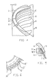
- FIG. 3 is a rear view of the yarn braking body of FIG. 2,
- FIG. 4 is a magnified section of the sectional view of FIG. 2,
- FIG. 5 is a further magnified section from FIG. 2, and
- FIG. 6 is a fragmentary view of an alternative embodiment of the yarn braking body.
- a yarn feeding device F in FIG. 1 has the task to pull a yarn Y from a yarn bobbin (in FIG. 1, left side, not shown), to intermediately store the yarn in turns on a stationary storage body 4 , and to allow a textile machine, e.g. a weaving machine, to withdraw said yarn through a yarn brake B with essentially constant yarn tension, which yarn brake B is structurally integrated into said yarn feeding device F.
- a rotary drive 2 for a winding element 2 a is provided in a housing 1 . The rotary drive 2 and the winding element 2 a intermediately store the yarn on the storage body in a yarn supply the size of which always is sufficient to cover the momentary consumption of the textile machine.
- a housing bracket 8 carries a withdrawal eyelet 5 .
- a sley 7 is adjustable along said housing bracket 8 . Adjustments of said sley 7 vary the braking effect.
- Sley 7 carries a carrier 6 which holds a ring-shaped yarn braking body A such that yarn braking body A is pressed with a frustoconical braking band S against a rounded withdrawal rim of the storage body 4 (FIG. 2 ).
- the yarn Y is pulled through between the withdrawal rim and the inner surface of the braking band S, and the yarn withdrawal point orbits around the withdrawal rim.
- the yarn braking body A shown in FIGS. 2 to 5 with differing details has an annular holding membrane M made from rubber or plastic material, e.g. from polyurethane.
- Holding membrane M may be made transparent.
- holding membrane M is a unitary injection molded part.
- a frustoconical, endless braking band S is positioned in the inner portion of said holding membrane M.
- Braking band S preferably is made from a metal alloy.
- holding membrane M could be made from a compound material, e.g. with the use of Kevlar.
- Adjacent to a circular holding area 11 a conical skirt 10 extends inwardly in said holding membrane M.
- holding membrane M is formed with a generally C-shaped bend L which extends via an essentially 90° transition into an outer carrier ring R.
- Carrier ring R is concentric to braking band S.
- carrier ring R may be made as a separate structural component and connected with holding membrane M.
- the bend L defines an outer annular region 9 of holding membrane M.
- Said outer annular region 9 contains area portions D (FIG. 4) each having reduced wall thickness S 1 smaller than the normal membrane wall thickness S 2 .
- Said area portions D are distributed in the circumferential direction.
- the area portions D e.g. form oval intermediate spaces (FIG. 3) between spring spokes E each e.g. of wall thickness S 2 .
- Said spring spokes are arranged essentially like beams and are integrated into the annular region 9 of holding membrane M.
- the ratio between wall thickness S 2 and wall thickness S 1 may be about 5:1. In case of a wall thickness S 2 of about 1.0 mm, wall thickness S 1 may be about 0.2 mm.
- annular region section 9 is formed with an essentially smooth surface 12 .
- groove-shaped depressions are formed due to the reduced wall thickness S 1 .
- the area portions D can be formed oval and may be oriented essentially radially with respect to the axis of yarn braking body A. This is also true for spring spokes E.
- FIG. 6 shows an alternative embodiment of a braking band having a holding membrane M′.
- the widths of the area portions D′ are different (e.g. smaller) than the widths of spring spokes E′.
- the area portions D commonly begin at a distance from holding area 11 for braking band S.
- a circumferentially continuous lip 13 (FIG. 5) extends freely inwardly.
- Lip 13 and skirt 10 form an insertion pocket T for the outer edge of braking band S.
- Said insertion pocket is inwardly open and extends around the circumference.
- the free length of lip 13 e.g. corresponds to a fifth of the width W of braking band S.
- Insertion pocket T is located essentially in the same radial plane as the transition from the annular region 9 into the carrier ring R.
- lip 13 could be omitted. Then braking band S could be secured at skirt 10 by gluing.
- the radial extension of annular region 9 of holding membrane M essentially corresponds to the radial extension of braking band S.
- the wall thickness of skirt 10 may be smaller than wall thickness S 2 of the spring spokes E but should be larger than wall thickness S 1 of membrane layers G which bridge the intermediate spaces between the spring spokes E within area portions D. In the embodiment as shown the area portions D continuously are covered by said membrane layers G. Alternatively it is possible to only bridge the inner parts of the area portions D by the membrane layers G and to leave outside open passages.
- the geometrical form of the area portions D having reduced wall thickness S 1 can be selected voluntarily as well as the distribution and orientation of the area portions D in annular region 9 of holding membrane M. Expediently, the spring spokes E and the area portions D are regularly distributed in circumferential direction.
Landscapes
- Engineering & Computer Science (AREA)
- Textile Engineering (AREA)
- Knitting Machines (AREA)
- Yarns And Mechanical Finishing Of Yarns Or Ropes (AREA)
- Diaphragms And Bellows (AREA)
- Tape Measures (AREA)
- Injection Moulding Of Plastics Or The Like (AREA)
- Springs (AREA)
- Tension Adjustment In Filamentary Materials (AREA)
- Braking Arrangements (AREA)
Applications Claiming Priority (3)
| Application Number | Priority Date | Filing Date | Title |
|---|---|---|---|
| DE19911943 | 1999-03-17 | ||
| DE19911943A DE19911943A1 (de) | 1999-03-17 | 1999-03-17 | Fadenliefergerät und Fadenbremskörper |
| PCT/EP2000/002362 WO2000055081A1 (de) | 1999-03-17 | 2000-03-16 | Fadenliefergerät und fadenbremskörper |
Publications (1)
| Publication Number | Publication Date |
|---|---|
| US6637692B1 true US6637692B1 (en) | 2003-10-28 |
Family
ID=7901336
Family Applications (1)
| Application Number | Title | Priority Date | Filing Date |
|---|---|---|---|
| US09/936,575 Expired - Fee Related US6637692B1 (en) | 1999-03-17 | 2000-03-16 | Yarn feeding device and yarn braking body |
Country Status (7)
| Country | Link |
|---|---|
| US (1) | US6637692B1 (de) |
| EP (1) | EP1163180B1 (de) |
| KR (1) | KR100457304B1 (de) |
| CN (1) | CN1201990C (de) |
| AT (1) | ATE241558T1 (de) |
| DE (2) | DE19911943A1 (de) |
| WO (1) | WO2000055081A1 (de) |
Cited By (1)
| Publication number | Priority date | Publication date | Assignee | Title |
|---|---|---|---|---|
| US20020134872A1 (en) * | 2001-03-20 | 2002-09-26 | L.G.L. Electronics S.P.A. | Self-adjusting braking device for weft feeders |
Citations (12)
| Publication number | Priority date | Publication date | Assignee | Title |
|---|---|---|---|---|
| US4429723A (en) * | 1980-10-15 | 1984-02-07 | Roj Electrotex S.P.A. | Yarn braking means for yarn feeding devices |
| US5343899A (en) * | 1990-03-12 | 1994-09-06 | Iro Ab | Output yarn brake |
| WO1994020402A1 (en) | 1993-02-23 | 1994-09-15 | Nuova Roj Electrotex S.R.L. | Yarn feeder |
| WO1995000431A1 (en) | 1993-06-17 | 1995-01-05 | Nuova Roj Electrotex S.R.L. | Yarn feeder |
| US5409043A (en) * | 1991-09-20 | 1995-04-25 | Zenoni; Pietro | Annular thread braking band for weft feeder |
| US5546994A (en) * | 1994-10-14 | 1996-08-20 | Sobrevin Societe De Brevets Industriels-Etablissement | Thread storage drum with frustoconical brake strip |
| US5678779A (en) * | 1992-11-23 | 1997-10-21 | Nuova Roj Electrotex S.R.L. | Yarn feeding device with self-adjusting braking mechanism |
| US5769132A (en) * | 1993-09-15 | 1998-06-23 | Iro Ab | Projectile or gripper shuttle loom with anti-ballooning cone for weft feeder |
| WO1998038124A1 (de) | 1997-02-24 | 1998-09-03 | Iro Ab | Fadenliefergerät und fadenbremse |
| WO1999064337A1 (en) | 1998-06-10 | 1999-12-16 | Nuova Roj Electrotex S.R.L. | Yarn brake, particularly for yarn feeders of looms |
| US6125892A (en) * | 1996-08-29 | 2000-10-03 | Iro Ab | Yarn feeding apparatus and braking device including an elastic annular membrane |
| US6257516B1 (en) * | 1996-04-01 | 2001-07-10 | Iro Ab | Axial disc brake and yarn feeding device including an axial disc brake |
-
1999
- 1999-03-17 DE DE19911943A patent/DE19911943A1/de not_active Withdrawn
-
2000
- 2000-03-16 CN CNB008063818A patent/CN1201990C/zh not_active Expired - Fee Related
- 2000-03-16 KR KR10-2001-7011727A patent/KR100457304B1/ko not_active IP Right Cessation
- 2000-03-16 AT AT00916966T patent/ATE241558T1/de not_active IP Right Cessation
- 2000-03-16 US US09/936,575 patent/US6637692B1/en not_active Expired - Fee Related
- 2000-03-16 DE DE50002363T patent/DE50002363D1/de not_active Expired - Fee Related
- 2000-03-16 EP EP00916966A patent/EP1163180B1/de not_active Expired - Lifetime
- 2000-03-16 WO PCT/EP2000/002362 patent/WO2000055081A1/de active IP Right Grant
Patent Citations (13)
| Publication number | Priority date | Publication date | Assignee | Title |
|---|---|---|---|---|
| US4429723A (en) * | 1980-10-15 | 1984-02-07 | Roj Electrotex S.P.A. | Yarn braking means for yarn feeding devices |
| US5343899A (en) * | 1990-03-12 | 1994-09-06 | Iro Ab | Output yarn brake |
| US5409043A (en) * | 1991-09-20 | 1995-04-25 | Zenoni; Pietro | Annular thread braking band for weft feeder |
| US5678779A (en) * | 1992-11-23 | 1997-10-21 | Nuova Roj Electrotex S.R.L. | Yarn feeding device with self-adjusting braking mechanism |
| WO1994020402A1 (en) | 1993-02-23 | 1994-09-15 | Nuova Roj Electrotex S.R.L. | Yarn feeder |
| WO1995000431A1 (en) | 1993-06-17 | 1995-01-05 | Nuova Roj Electrotex S.R.L. | Yarn feeder |
| US5769132A (en) * | 1993-09-15 | 1998-06-23 | Iro Ab | Projectile or gripper shuttle loom with anti-ballooning cone for weft feeder |
| US5546994A (en) * | 1994-10-14 | 1996-08-20 | Sobrevin Societe De Brevets Industriels-Etablissement | Thread storage drum with frustoconical brake strip |
| US6257516B1 (en) * | 1996-04-01 | 2001-07-10 | Iro Ab | Axial disc brake and yarn feeding device including an axial disc brake |
| US6125892A (en) * | 1996-08-29 | 2000-10-03 | Iro Ab | Yarn feeding apparatus and braking device including an elastic annular membrane |
| WO1998038124A1 (de) | 1997-02-24 | 1998-09-03 | Iro Ab | Fadenliefergerät und fadenbremse |
| US6322016B1 (en) * | 1997-02-24 | 2001-11-27 | Iro Ab | Thread delivery device and thread brake |
| WO1999064337A1 (en) | 1998-06-10 | 1999-12-16 | Nuova Roj Electrotex S.R.L. | Yarn brake, particularly for yarn feeders of looms |
Cited By (2)
| Publication number | Priority date | Publication date | Assignee | Title |
|---|---|---|---|---|
| US20020134872A1 (en) * | 2001-03-20 | 2002-09-26 | L.G.L. Electronics S.P.A. | Self-adjusting braking device for weft feeders |
| US6752177B2 (en) * | 2001-03-20 | 2004-06-22 | L.G.L. Electronics S.P.A. | Self-adjusting braking device for weft feeders |
Also Published As
| Publication number | Publication date |
|---|---|
| EP1163180B1 (de) | 2003-05-28 |
| KR20020002403A (ko) | 2002-01-09 |
| WO2000055081A1 (de) | 2000-09-21 |
| DE19911943A1 (de) | 2000-09-21 |
| CN1201990C (zh) | 2005-05-18 |
| DE50002363D1 (de) | 2003-07-03 |
| CN1352617A (zh) | 2002-06-05 |
| KR100457304B1 (ko) | 2004-11-16 |
| ATE241558T1 (de) | 2003-06-15 |
| EP1163180A1 (de) | 2001-12-19 |
Similar Documents
| Publication | Publication Date | Title |
|---|---|---|
| US6322016B1 (en) | Thread delivery device and thread brake | |
| US5409043A (en) | Annular thread braking band for weft feeder | |
| JPH05506892A (ja) | 糸制動システム | |
| KR100310954B1 (ko) | 위사공급기 | |
| US6637692B1 (en) | Yarn feeding device and yarn braking body | |
| EP1027274B1 (de) | Fadenbremsvorrichtung in fadenliefergerät für webmaschinen und bremseinheit für diese vorrichtung | |
| MXPA06013334A (es) | Polea de impulso y guia de banda de una sola pieza. | |
| EP0670810B1 (de) | Garnliefervorrichtung | |
| US6125892A (en) | Yarn feeding apparatus and braking device including an elastic annular membrane | |
| EP1091900B1 (de) | Garnbremse, insbesondere für fadenliefervorrichtungen in webmaschinen | |
| EP0951436B1 (de) | Fadenbremse für schussfadenliefervorrichtungen | |
| JPS6213267B2 (de) | ||
| EP1796993B1 (de) | Fadenbremskörper | |
| EP2623650B1 (de) | Fadenbremse für Vorspulgerät | |
| EP1164103B1 (de) | Bremse für eine selbstregulierende Fadenbremse einer Schussfadenliefervorrichtung | |
| KR100305118B1 (ko) | 방적사공급기 | |
| JP5648669B2 (ja) | 緯糸測長貯留装置の緯糸送り羽根調整工具 | |
| JP7082897B2 (ja) | ガイドローラ | |
| EP1526102B1 (de) | Bremsvorrichtung für Schussfäden für Textilmaschinen | |
| EP0957058B1 (de) | Selbsteinstellende Fadenbremsvorrichtung für Fadenliefervorrichtungen | |
| JPH09183570A (ja) | 撚糸スピンドルのヤーンガイド | |
| JPH111833A (ja) | 解じょ糸のガイド装置 |
Legal Events
| Date | Code | Title | Description |
|---|---|---|---|
| AS | Assignment |
Owner name: IROPA AG, SWITZERLAND Free format text: ASSIGNMENT OF ASSIGNORS INTEREST;ASSIGNOR:JACOBSSON, KURT ARNE GUNNAR;REEL/FRAME:012599/0988 Effective date: 20011219 |
|
| REMI | Maintenance fee reminder mailed | ||
| LAPS | Lapse for failure to pay maintenance fees | ||
| STCH | Information on status: patent discontinuation |
Free format text: PATENT EXPIRED DUE TO NONPAYMENT OF MAINTENANCE FEES UNDER 37 CFR 1.362 |
|
| FP | Lapsed due to failure to pay maintenance fee |
Effective date: 20071028 |