US6278677B1 - Disk loading device having disk holding tray separable into a plurality of segments - Google Patents
Disk loading device having disk holding tray separable into a plurality of segments Download PDFInfo
- Publication number
- US6278677B1 US6278677B1 US08/978,151 US97815197A US6278677B1 US 6278677 B1 US6278677 B1 US 6278677B1 US 97815197 A US97815197 A US 97815197A US 6278677 B1 US6278677 B1 US 6278677B1
- Authority
- US
- United States
- Prior art keywords
- tray
- disk
- cam
- loading device
- pinions
- Prior art date
- Legal status (The legal status is an assumption and is not a legal conclusion. Google has not performed a legal analysis and makes no representation as to the accuracy of the status listed.)
- Expired - Fee Related
Links
Images


Classifications
-
- G—PHYSICS
- G11—INFORMATION STORAGE
- G11B—INFORMATION STORAGE BASED ON RELATIVE MOVEMENT BETWEEN RECORD CARRIER AND TRANSDUCER
- G11B17/00—Guiding record carriers not specifically of filamentary or web form, or of supports therefor
- G11B17/22—Guiding record carriers not specifically of filamentary or web form, or of supports therefor from random access magazine of disc records
- G11B17/225—Guiding record carriers not specifically of filamentary or web form, or of supports therefor from random access magazine of disc records wherein the disks are transferred from a fixed magazine to a fixed playing unit using a moving carriage
Definitions
- the present invention relates to a disk loading device for loading disks as information recording mediums, such as optical disks and magneto-optic disks, into a disk apparatus main body.
- Optical disks and magneto-optic disks have recently gained wide popularity as information recording mediums, and created demands for a disk loading device capable of storing a plurality of disks at one time to realize easy handling of a plurality of disks. Accordingly, various types of disk loading devices have been invented.
- Japanese Laid-Open Patent Application No. 7-282520/1995 discloses a disk reproducing device which meets the requirements.
- the disk reproducing device includes a pair of a main tray and a subtray.
- the subtray moves a disk between a disk replacement position outside the housing and a reproduction position.
- the subtray is held by the main tray so as to be movable between the disk replacement position and a standby position inside the housing.
- An individual rack is provided to the subtray and the main tray, and one pinion engages one of two racks.
- the pinion is elevated and lowered along the rotation axis thereof by pinion moving means that includes a pinion elevating and lowering cam, and shifts to a position where it engages one of the two racks.
- the pinion elevating and lowering cam is a cylinder with a plurality of cam surfaces in accordance with the position of the pinion.
- the disk reproducing device includes a fluctuation gear and a reproducing section elevating and lowering cam for elevating and lowering a reproducing mechanism.
- the reproducing section elevating and lowering cam is a cylinder cam with a plurality of cam surfaces in accordance with the position of the reproducing section, for elevating and lowering the reproducing section that includes a turn table, an optical pickup unit, etc.
- the fluctuation gear fluctuates depending upon the rotation direction of the motor and thereby rotates either the pinion elevating and lowering cam or the reproducing section elevating and lowering cam. Two kinds of cams can be driven with a single motor in this manner.
- the pinion is driven upward and downward so as to engage the rack of one of the trays during the reciprocal movement of the main tray between the disk replacement position and the standby position and the reciprocal movement of the subtray between the standby position and the reproduction position.
- This requires both the subtray and the main tray to be provided with an individual rack, adding to the costs for the disk reproducing device.
- a method of removing such inconvenience is to remove the subtray and change the configuration of the disk reproducing device so that the disk can be moved only by the main tray.
- This configuration requires a portion of the main tray on which the disk is mounted to be movable between the disk replacement position and the reproduction position, and therefore that the main tray travel a longer distance than that in the previous configuration including the subtray. Consequently, the disk reproducing device needs a larger housing to allow for that travel distance for the main tray.
- Displacement of the rack is eliminated by slightly moving the pinion and thus correcting the engagement position of the pinion with the rack.
- the pinion is slightly moved until the rack is back in the right engagement position, and then driven at a speed predetermined to move the tray. Therefore, the method requires a device for detecting that the rack has reached its right engagement position, and may complicate the controls of the tray moving means for driving the pinion.
- Relative displacement between the racks can also be eliminated by moving the pinion as much as the racks have been disposed.
- the pinion is horizontally moved until the pinion is in the right position to engage the disposed rack. Therefore, the method requires a mechanism for moving the pinion relative to the subtray or the main tray.
- a pinion elevating and lowering cam and a reproducing section elevating and lowering cam are provided separately, one of the cams is selectively driven by a single motor.
- the drive mechanism turns the cams in fixed directions using the fluctuation gears engaging one of gears provided to the cams.
- the operation proceeds to a reproduction preparatory movement for a disk on a lower (upper) shelf.
- the operation proceeds either to an upper shelf or to a lower shelf. Therefore, the cams need two cam surfaces of the same height on both sides of the highest cam surface and the lowest cam surface.
- a device may possibly be needed for detecting the position of the pinion and that of the reproducing section, and complicate the controls of the tray moving means.
- the pinion engages only the rack of the main tray, not the rack of the subtray. Therefore, the subtray may possibly be moved and disposed relative to the main tray, while the main tray is being moved.
- the pinion when in the standby and reproduction positions and between those positions, does not engage the rack of the main tray, and is only held by the housing.
- An electrically driven holding mechanism is needed to hold the pinion, and the main tray needs to be so thick and strong to be held by the holding mechanism.
- the holding mechanism needs to release the main tray when the rack of the main tray engages the pinion. If the main tray is not released at the right timing, the main tray cannot shift from the holding state to the moving state.
- the reproducing section including the turn table and an optical pickup unit do not contact the moving disk during the turning movement of the reproducing section elevating and lowering cam
- the reproducing section retreats downward relative to the subtray moving to the reproduction position, and when the subtray reaches the reproduction position the disk is scooped with the reproducing section moved upward.
- a damper provided to the reproducing section so as to be turned up and down is lowered to secure the disk to the turn table. Therefore, a mechanism for vertically turning the damper is provided for that purpose only. Besides, since the damper is lowered obliquely, the disk cannot be firmly secured to the turn table in some cases.
- the disk reproducing device requires a detecting device for detecting the disk replacement position, the standby position, and the reproduction position, a detecting device for detecting the position of the pinion (the rotation position of the pinion elevating and lowering cam), and a detecting device for detecting the position of the reproducing section (the rotation position of the reproducing section elevating and lowering cam), each detecting device being provided separately from the others.
- a detecting device for detecting the securing of the disk by the damper and the release of the securing needs to be provided. Therefore, the controls of the disk loading is carried out on the basis of the three or four kinds of detection signals from the detecting devices, which complicates the controls.
- the present invention has as its principal object the provision of a disk loading device having a simply configured tray drive mechanism without a larger housing. Another important object of this invention is to provide a disk loading device that is free from the drawbacks mentioned above.
- a disk loading device in accordance with the present invention has:
- a first tray provided so as to be freely movable with a disk thereon among a loading and unloading position for allowing loading and unloading of the disk outside a housing, a storage position for storing the disk inside the housing, and a reproduction position for reproducing the disk at the back of the storage position in the housing;
- a second tray provided so as to be freely movable with the first tray thereon between the loading and unloading position and the storage position;
- tray driving mechanism for driving and reciprocally moving the first tray among the three positions
- a holding member for holding the second tray onto the first tray
- hold releasing mechanism for releasing the hold by the holding member when the first tray moves from the storage position to the reproduction position.
- the configuration allows the second tray to be held by the holding member onto the first tray between the loading and unloading position and the storage position, thereby enhancing the strength of the first tray between the loading and unloading position and the storage position. This realizes reliable movement of the disk between the loading and unloading position and the storage position.
- the tray driving mechanism only needs to drive the first tray, enabling the tray driving mechanism to be configured simply.
- the configuration when moving the first tray from the storage position to the reproduction position, lets the hold releasing mechanism release the second tray that is held onto the first tray by the holding member, and thereby moves the first tray alone. Since only the first tray is moved from the storage position to the reproduction position in this manner, it is needless to provide the disk loading device with a large housing.
- FIG. 1 ( a ) is a plan view showing movements between three positions of an upper tray and a lower tray of a disk loading device of an embodiment in accordance with the present invention.
- FIGS. 1 ( b ) through 1 ( d ) are side views showing the movements between the three positions of the upper tray and the lower tray.
- FIG. 2 is a perspective view showing the appearance of the disk loading device.
- FIGS. 3 ( a ) and 3 ( b ) are plan views showing two kinds of disks loaded in the disk loading device.
- FIG. 4 ( a ) is a plan view showing a configuration of the upper tray.
- FIG. 4 ( b ) is a plan view showing a configuration of the lower tray.
- FIG. 5 ( a ) is a perspective view showing a configuration of the upper tray and the lower tray being separated from each other.
- FIG. 5 ( b ) is a perspective view showing a configuration of the upper tray and the lower tray constituting a tray assembly.
- FIG. 6 is a plan view showing a layout inside the disk loading device.
- FIGS. 7 ( a ) through 7 ( c ) are plan views showing an ON state and an OFF state of tray position detecting switches in accordance with the position of the upper tray of the disk loading devices of the embodiment and another embodiment in accordance with the present invention.
- FIGS. 8 ( a ) through 8 ( c ) are plan views showing an ON state and an OFF state of tray position detecting switches in accordance with the position of the lower tray of the disk loading devices of the embodiment and another embodiment in accordance with the present invention.
- FIG. 9 is a perspective view showing the appearance of a reproducing mechanism unit.
- FIG. 10 is a perspective view showing the appearance of a disk securing unit.
- FIG. 11 is a side view showing a configuration of a main cam and components associated with the main cam.
- FIG. 12 is a perspective view showing the appearance of the main cam.
- FIGS. 13 ( a ) and 13 ( b ) are a plan view and a side view, respectively, showing the locations of the two pinions when the upper tray is in the storage position.
- FIGS. 14 ( a ) and 14 ( b ) are a plan view and a side view, respectively, showing the locations of the two pinions when the upper tray is moved from the storage position to the loading and unloading position.
- FIGS. 15 ( a ) and 15 ( b ) are a plan view and a side view, respectively, showing the locations of the two pinions when the upper tray is moved from the storage position to the reproduction position.
- FIGS. 16 ( a ), 16 ( c ) and 16 ( e ) are plan views showing the holding state of the lower tray onto the upper tray by a lock lever in the loading and unloading position, in an immediately prior position to the storage position in a movement from the loading and unloading position, and in a storage position respectively.
- FIGS. 16 ( b ), 16 ( d ) and 16 ( f ) are side views respectively corresponding to the holding states shown in FIGS. 16 ( a ), 16 ( c ) and 16 ( e ).
- FIG. 17 is a perspective view showing the appearance of a disk loading device of another embodiment in accordance with the present invention.
- FIG. 18 is a perspective view showing the appearance of a driving unit of the disk loading device shown in FIG. 17 .
- FIG. 19 is a side view showing a configuration of a main cam and components associated with the main cam of the disk loading device shown in FIG. 17 .
- FIG. 20 ( a ) is a plan view showing movements between three positions of an upper tray and a lower tray of the disk loading device shown in FIG. 17 .
- FIGS. 20 ( b ) through 20 ( d ) are side views showing the movements between the three positions of the upper tray and the lower tray.
- FIG. 21 ( a ) is a development drawing showing an outer circumferencial surface of the main cam, shown in FIG. 19, projected and stretched like a narrow band.
- FIGS. 21 ( b ) and 21 ( c ) are development drawings showing an inner circumferencial surface of the main cam, shown in FIG. 19, projected and stretched like a narrow band.
- FIGS. 22 ( a ) and 22 ( b ) are plan and front views, respectively, showing a structure of pinion turning cams of the main cam of the disk loading device shown in FIG. 17 .
- FIG. 23 is a perspective view showing a configuration of a tray position detecting mechanism of the disk loading device shown in FIG. 17 .
- FIG. 24 is an explanatory drawing showing the positions of a turn table and a stabilizer of the disk loading device shown in FIG. 17 .
- FIG. 25 is a state transient drawing showing transitions of operation states of various sections corresponding to the rotation positions of the main cam of the disk loading device shown in FIG. 17 .
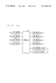
- FIG. 26 is a block diagram showing a control system for controlling the disk loading device shown in FIG. 17 .
- FIGS. 1 through 16 the following description will discuss an embodiment in accordance with the present invention.
- a disk loading device of the present embodiment includes, as shown in FIG. 2, a housing 1 encasing, for example, an upper tray 2 , a lower tray 3 , a tray driving mechanism 4 , a reproducing mechanism unit 5 , and a disk securing mechanism 16 .
- the upper tray 2 and the lower tray 3 are attached to the housing 1 so as to be freely movable in the directions indicated by the arrows, transporting a disk 6 shown in FIG. 3 ( a ) or a disk 7 shown in FIG. 3 ( b ) as an information recording medium from outside to the reproducing mechanism unit 5 located in the housing 1 at the back thereof and vice versa.
- the upper tray 2 as a first tray, as shown in FIG. 4 ( a ), has two round concave portions 2 a and 2 b of different diameters.
- the concave portion 2 a is formed to store the disk 6 of a greater diameter shown in FIG. 3 ( a ), whereas the concave portion 2 b is formed to store the disk 7 of a smaller diameter shown in FIG. 3 ( b ).
- the upper tray 2 transports the disk 6 to a loading and unloading position T 1 , a storage position T 2 , and a reproduction position T 3 as shown in FIG. 1 ( a ).
- the loading and unloading position T 1 is for loading and unloading of the disk 6 into and out of the upper tray 2 outside the housing 1 .
- the storage position T 2 is for storing the disk 6 inside the housing 1 and is in the neighborhood of an open portion 1 a (shown in FIG. 1 ( a )) through which the upper tray 2 moves into and out of the housing 1 .
- the reproduction position T 3 is located in the housing 1 at the back of the storage position T 2 for reproduction of the disk 6 .
- the upper tray 2 has a notch 2 c that has a U-like shape.
- the notch 2 c is formed so that a pickup 51 b (will be described later in detail; see FIG. 6 or 9 ) moves up to where it can read and write information on the disk 6 and so that a turn table 51 a (will be described later in detail; see FIG. 9) can scoop up the disk 6 from below.
- the upper tray 2 as shown in FIGS. 4 ( a ) and 5 ( a ), has guiding sections 2 d on its lower surface along one of its sidelines extending parallel to the direction of movement, and has a guide rail 2 e on its lower surface along the opposing sideline.
- the guide rail 2 e has the same structure as the guiding section 2 d and is provided along the sideline of the upper tray 2 for almost its whole length.
- the upper tray 2 has a position detecting cam 2 f and 2 g for detecting the position of the upper tray 2 on its side surface where the guiding section 2 d are disposed.
- the position detecting cam 2 f has almost the same length as the diameter of the concave portion 2 a , with one end on the edge of the upper tray 2 near the open portion la (front edge).
- the position detecting cam 2 g is formed in groove-like shape beneath the position detecting cam 2 f , and extends from a neighborhood of the front edge to the back edge of the upper tray 2 .
- the upper tray 2 has a rack 2 h on its side surface where the guide rail 2 e is disposed.
- the rack 2 h is provided so as to cover almost the whole length of that side surface except a predetermined part near the front edge.
- the rack 2 h has a collide-and-hold section 2 i protruding downward from a predetermined part of the rack 2 h .
- the collide-and-hold section 2 i is formed to collide with a lock claw 36 b (will be described later in detail; see FIG. 13 ).
- a stopper 2 j is provided near the rack 2 h on the front edge.
- the stoppers 2 j has an L-like shape and protrudes downward from the lower surface of the upper tray 2 , so as to catch and hold a lock lever 8 (will be described later in detail).
- the upper tray 2 is provided on the inner side of the rack 2 h with a guide hole 2 k piercing through the upper tray 2 .
- the guide hole 2 k is for the reproducing mechanism unit 5 to hold the upper tray 2 .
- the lower tray 3 as a second tray, as shown in FIGS. 4 ( b ) and 5 ( b ), has a guide rail 3 a on its upper surface along its sideline extending parallel to the direction of movement, and has guide sections 3 b on its upper surface along the opposing sideline.
- the guide rail 3 a has an L-like shape protruding upward and is provided along the sideline of the lower tray 3 for almost its whole length.
- Three guide sections 3 b are provided at appropriate intervals between thereof, each being a small plate-like piece protruding inward.
- the lower tray 3 is held to the upper tray 2 by the guiding sections 2 d catching and holding the guide rail 3 a and the guide rail 2 e catching and holding the guide sections 3 b .
- Upper tray 2 can freely slide between the storage position T 2 and the reproduction position T 3 .
- the lower tray 3 has a partial rack 3 c on its side surface where the guide section 3 b is disposed.
- the partial rack 3 c as an auxiliary rack is provided to be very short, compared to the rack 2 h , and is separated from the edge of the lower tray 3 near the open portion 1 a (front edge) by a predetermined distance.
- the partial rack 3 c and the rack 2 h both engage pinions 21 and 22 (will be described later in detail) .
- the lower tray 3 has a notch 3 d in almost the middle of the side surface where the rack 2 h is provided.
- the notch 3 d is formed to catch a lock claw 36 c (will be described later in detail).
- the lower tray 3 has position detecting cams 3 e and 3 f for detecting the position of the lower tray 3 on its side surface where the guide rail 3 a of the lower tray 3 is disposed.
- the position detecting cam 3 e is formed to cover the whole length of the side surface except the segment from the front edge of the lower tray 3 to a neighborhood of a point opposing the back end of the partial rack 3 c .
- the position detecting cam 3 f is formed in a groove-like shape beneath the position detecting cam 3 e , and extends from a point which is behind the front end of the position detecting cam 3 e to the back edge of the lower tray 3 .
- a tray assembly 10 is constituted by the upper tray 2 and the lower tray 3 configured as above, as well as the lock lever 8 as a holding member and a spring 9 .
- the lock lever 8 includes an L-shaped, plate-like lever main body 8 b .
- the lever main body 8 b is supported by a pin 3 g provided near the partial rack 3 c of the lower tray 3 so as to turn freely.
- the spring 9 is disposed between the lock lever 8 and the pin 3 g . As shown in FIG. 5 ( b ), the lock lever 8 is pressed by the spring 9 so as to stick out its head.
- the lock lever 8 has a protrusion section 8 a , protruding upward, for being caught by the stopper 2 j.
- the lock lever 8 with such a structure lets the upper tray 2 hold the lower tray 3 as shown in FIG. 16 ( a ).
- a tray position detecting mechanism 15 shown in FIG. 6 detects the positions of the upper tray 2 and the lower tray 3 .
- the tray position detecting mechanism 15 is provided on a side wall of the housing 1 , and constituted by four switch levers 11 through 14 and tray position detecting switches (hereinafter will be referred to as switches) SW 1 through SW 4 .
- the switch levers 11 through 14 are attached to the housing 1 so as to turn freely, and turns on or off the respective switches SW 1 through SW 4 in conjunction with the operation of the tray assembly 10 .
- the switch lever 11 for operating the switch SW 1 is constituted by a supporting section 11 a , a contact section 11 b , a lever section 11 c , and an operating section 11 d .
- the supporting section 11 a is formed in a column shape so as to be supported by the housing 1 and to turn freely.
- the contact section 11 b is provided to the supporting section 11 a so as to contact the position detecting cam 3 f .
- the lever section 11 c is provided so as to extend from the lower end of the supporting section 11 a toward the switch SW 1 provided inside the housing 1 .
- the operating section 11 d is a flat plate provided on the tip of the lever section 11 c and operates the actuator of the switch SW 1 by a turning movement of the lever section 11 c.
- the switch lever 12 for operating the switch SW 2 is constituted in the same manner as the switch lever 11 , namely, by a supporting section 12 a , a contact section 12 b , a lever section 12 c , and an operating section 12 d .
- the contact section 12 b is provided to the supporting section 12 a so as to contact the position detecting cam 3 e.
- the switch lever 13 for operating the switch SW 3 is constituted by a supporting section 13 a , a contact section 13 b , a lever section 13 c , and an operating section 13 d .
- the supporting section 13 a is formed in a column shape so as to be supported by the housing 1 and to turn freely.
- the contact section 13 b is provided to the supporting section 13 a so as to contact the position detecting cam 2 g .
- the lever section 13 c is provided so as to extend from the lower end of the supporting section 13 a toward the switch SW 3 provided inside the housing 1 .
- the operating section 13 d is a flat plate provided on the tip of the lever section 13 c , and operates the actuator of the switch SW 3 by a turning movement of the lever section 13 c.
- the switch lever 14 for operating the switch SW 4 is constituted in the same manner as the switch lever 13 , namely, by a supporting section 14 a , a contact section 14 b , a lever section 14 c , and an operating section 14 d .
- the contact section 14 b is provided to the supporting section 14 a so as to contact the position detecting cam 2 f.
- the switches SW 1 through SW 4 are pressed by springs (not shown) when they are not in contact with the respective position detecting cams 2 f , 2 g , 3 e , and 3 f.
- the tray position detecting mechanism 15 configured in this manner detects the positions of the upper tray 2 and the lower tray 3 by combinations of the ON and OFF states of the four switches SW 1 through SW 4 .
- the following description will explain the ON and OFF states of the switches SW 1 through SW 4 in accordance with the positions of the upper tray 2 and the lower tray 3 .
- the tray driving mechanism 4 as tray driving means is constituted by the two pinions 21 and 22 , a pinion pulley 23 , a pinion drive belt 24 , pressure rollers 25 and 26 , gears 27 through 30 , a drive pulley 31 , a drive belt 32 , a pinion rotating motor 33 , and a pinion turning mechanism 35 .
- the pinion turning mechanism 35 as pinion turning means is constituted by a base 36 , a joint lever 37 , and pinion turning cams 41 a (will be described later in detail; see FIG. 12 ).
- the tray driving mechanism 4 is provided with the pinion pulley 23 and the pinion drive belt 24 , two pairs of gears 39 and a pinion gear 40 may be used instead of the pinion pulley 23 and the pinion drive belt 24 as shown in FIG. 2 .
- the pair of gears 39 are driven by pinion gears 40 .
- the pinions 21 and 22 , the pinion pulley 23 , and the pressure rollers 25 and 26 are disposed on the base 36 so as to be freely rotatable.
- the pinions 21 and 22 are moved by the pinion turning mechanism 35 to a position where they engage the rack 2 h of the upper tray 2 .
- the pinion pulley 23 is disposed between the pinions 21 and 22 , and rotates the pinions 21 and 22 with the pinion drive belt 24 .
- the pressure rollers 25 and 26 press the pinion drive belt 24 onto the pinion pulley 23 on both sides of the pinion pulley 23 .
- the gear 27 is disposed below the pinion pulley 23 and is coaxially attached to the pinion pulley 23 by a shaft 38 (see FIG. 11 ).
- the gear 27 engages the gear 28
- the gear 28 engages the gear 29 in turn
- the gear 29 then engages the gear 30 .
- the gear 30 is coaxially attached to the drive pulley 31 by a shaft.
- the drive belt 32 is wound around the drive pulley 31 and a motor pulley 33 a provided coaxially with the pinion rotating motor 33 .
- Such a drive force transmitting mechanism transmits drive force generated by the pinion rotating motor 33 to drive the pinions 21 and 22 and the pinion pulley 23 .
- the base 36 is supported by the shaft 38 so as to turn freely around the center of rotation of the pinion pulley 23 .
- the base 36 includes a turning edge 36 a , and lock claws 36 b and 36 c .
- the turning edge 36 a is provided on an end closer to the pinion 22 .
- the lock claw 36 b is provided between the pressure roller 25 and the pinion 21 .
- the lock claw 36 c is provided between the pressure roller 26 and the pinion 22 .
- the lock claws 36 b and 36 c stick out toward the rack 2 h as shown in FIG. 13 .
- the joint lever 37 is constituted by a main body 37 a and a claw section 37 b .
- the main body 37 a has a tip of a U-like shape to hold the turning edge 36 a in a flanking manner.
- the claw section 37 b as shown in FIG. 6, has a claw on both ends, and is secured to the main body 37 a and supported by the housing 1 so as to turn freely.
- the main body 37 a fluctuates as the claw section 37 b contacts the pinion turning cams 41 a which have convexities and concavities.
- the base 36 is turned by the fluctuation of the main body 37 a of the joint lever 37 .
- three states of the pinions 21 and 22 can be obtained: the states in which either the pinion 21 or 22 engages the rack 2 h (the states shown in FIGS. 14 and 15) and the state in which none of the pinions 21 and 22 engages the rack 2 h (the state shown in FIG. 13 ).
- the tray driving mechanism 4 includes the two pinions 21 and 22 for engaging the rack 2 h , the pinion pulley 23 , disposed between the pinions 21 and 22 , for rotating the pinions 21 and 22 , the pinion rotating motor 33 for driving and rotating the pinion pulley 23 , and the pinion turning mechanism 35 for turning the pinions 21 and 22 around the rotation axis of the pinion pulley 23 so as to locate the pinions 21 and 22 to the positions where the pinions 21 and 22 engage the rack 2 h and where they do not.
- a main cam 41 of a column-like shape is provided at the back of the housing 1 .
- the reproducing mechanism unit 5 , the disk securing mechanism 16 and the pinion turning mechanism 35 work in predetermined manners.
- the reproducing mechanism unit 5 and the disk securing mechanism 16 are disposed inside the main cam 41 .
- the reproducing mechanism unit 5 is constituted by a reproducing mechanism 51 , a holder 52 and a damper 53 .
- the holder 52 is a member for covering the reproducing mechanism 51 , and is attached to the reproducing mechanism 51 via the damper 53 .
- On the side walls of the holder 52 are provided three driven pins 52 a that catch and hold reproducing mechanism elevating and lowering cams 41 b (will be described later in detail; see FIG. 6 ).
- the driven pins 52 a elevate and lower the reproducing mechanism unit 5 as they are elevated and lowered by rotation of the main cam 41 .
- the holder 52 has on its upper surface a holding protrusion 52 b formed so as to stick upward.
- the holding protrusion 52 b is caught by the guide hole 2 k and thus holds the upper tray 2 .
- the reproducing mechanism 51 is constituted by, for instance, the turn table 51 a for rotating the disk 6 , a spindle motor (not shown) for rotating the turn table 51 a , and the pickup 51 b for optically reading and writing information on the disk 6 .
- the pickup 51 b is provided so as to be freely movable parallel to the straight line indicated by the arrow A—A.
- the reproducing mechanism 51 can incorporate not only a reproducing function but a recording function as well.
- the disk securing mechanism 16 is, as shown in FIG. 10, constituted by a stabilizer 54 and a stabilizer holder 55 .
- the stabilizer 54 is held by the stabilizer holder 55 so as to be freely rotatable.
- the disk 6 mounted on the turn table 51 a is secured by the stabilizer 54 so as to be freely rotatable during reproduction.
- the stabilizer holder 55 has a horizontal plate 55 a for holding the stabilizer 54 and a vertical plate 55 b disposed perpendicular to the horizontal plate 55 a .
- the vertical plate 55 b is provided on its upper and lower parts with five elevating and lowering guide pins 55 c , and on its lower part with a driven pin 55 d .
- the driven pin 55 d fits a securing mechanism elevating and lowering cam 41 c (will be described later in detail), and the main cam 41 rotates, the driven pin 55 d is elevated or lowered, and thereby elevates or lowers the stabilizer holder 55 together with the stabilizer 54 .
- the elevating and lowering guide pins 55 c fit a guide groove (not shown) provided to the housing 1 , and thus regulates the elevating and lowering of the stabilizer holder 55 to a fixed direction.
- the main cam 41 includes the pinion turning cams 41 a , the reproducing mechanism elevating and lowering cams 41 b , the securing mechanism elevating and lowering cam 41 c , and rotation position detecting cams 41 d .
- the main cam 41 is driven and rotated by a cam driving mechanism 61 .
- the main cam 41 has a gear 41 e provided all along the circumference of the bottom surface thereof.
- the cam driving mechanism 61 is, as shown in FIG. 6, constituted by gears 62 and 63 , a cam rotating pulley 64 , a cam rotating belt 65 , and a cam rotating motor 66 .
- the gear 62 engages the gear 41 e and the gear 63 .
- the gear 63 is coaxially attached to the cam rotating pulley 64 by the shaft 67 .
- the cam rotating belt 65 is wound around the cam rotating pulley 64 and the motor pulley 66 a provided coaxially with the cam rotating motor 66 .
- Such a drive force transmitting mechanism transmits drive force generated by the cam rotating motor 66 to drive the main cam 41 .
- the pinion turning cams 41 a are formed in pairs of a convexity and a concavity on an upper part of the outer circumferencial surface of the main cam 41 (see FIGS. 22 ( a ) and 22 ( b )), whereas the rotation position detecting cams 41 d are formed in a convex shape on a lower part of the outer circumferencial surface of the main cam 41 .
- the pinion turning cams 41 a are formed at predetermined intervals so as to move the joint lever 37 according to the positions of the upper tray 2 and the lower tray 3 .
- Some of the rotation position detecting cams 41 d are arranged in pairs side-by-side at the upper and lower locations as shown in FIG.
- the upper and lower locations correspond to the heights of respective cam position detecting switches (hereinafter will be referred to as switches) SW 11 and SW 12 .
- the rotation position detecting cams 41 d turn on and off the switches SW 11 and SW 12 in this manner.
- the switches SW 11 and SW 12 are mounted on the housing 1 as shown in FIG. 6, and are provided with a leaf spring on their tips, the leaf springs having contact portions that contact the rotation position detecting cams 41 d .
- the switches SW 11 and SW 12 are hence turned on when the contact portions touch the rotation position detecting cams 41 d and turned off when the contact portions do not touch the rotation position detecting cams 41 d .
- the rotation position of the main cam 41 can be detected on the basis of the four combinations of ON & OFF, OFF & ON, ON & ON, and OFF & OFF of the switches SW 11 and SW 12 in accordance with the arrangement of the locations of the rotation position detecting cams 41 d.
- the reproducing mechanism elevating and lowering cams 41 b are formed as three grooves so as to fulfill the following purposes: the reproducing mechanism elevating and lowering cams 41 b should move the three driven pins 52 a while fitting the driven pins 52 a , and, as the reproducing mechanism elevating and lowering cams 41 b rotate, should elevate and lower the reproducing mechanism 51 to predetermined positions for the reproduction and transportation of the disk 6 .
- a part of the reproducing mechanism elevating and lowering cam 41 b is formed obliquely so as to elevate and lower the reproducing mechanism unit 5 , and the rest is formed horizontally so as not to elevate or lower the reproducing mechanism unit 5 .
- the reproducing mechanism elevating and lowering cams 41 b are disposed at intervals corresponding to those of the driven pins 52 a so as to always maintain the reproducing mechanism 51 in a horizontal position.
- the securing mechanism elevating and lowering cam 41 c is formed as a single groove so as to move the stabilizer holder 55 while fitting the driven pin 55 d .
- a part of the securing mechanism elevating and lowering cam 41 c is also formed obliquely so as to elevate and lower the stabilizer holder 55 , and the rest is formed horizontally so as not to elevate and lower the stabilizer holder 55 .
- the arrangement of the locations of the pinion turning cams 41 a , and the shape of the reproducing mechanism elevating and lowering cams 41 b and the securing mechanism elevating and lowering cam 41 c are associated with the arrangement of locations of the rotation position detecting cams 41 d .
- the locations of the upper tray 2 , the lower tray 3 , the reproducing mechanism unit 5 , and the stabilizer 54 are detected on the basis of the ON and OFF states of the switches SW 11 and SW 12 .
- the main cam 41 has the aforementioned four kinds of cams, the upper tray 2 , the lower tray 3 , the reproducing mechanism 51 , and the stabilizer 54 are moved in an associated manner by the rotation of the main cam 41 .
- the pinion turning cams 41 a are provided integrally with the reproducing mechanism elevating and lowering cams 41 b , and formed in such a shape to generate movement that causes the pinions 21 and 22 to be turned when the reproducing mechanism elevating and lowering cams 41 b rotate.
- the pinion turning cams 41 a are formed as above, if the movement of the reproducing mechanism elevating and lowering cams 41 b is detected, the movement of the pinion turning mechanism 35 can also be detected.
- the location of the upper tray 2 and the reproducing mechanism 51 can be therefore detected by detecting the movement of the reproducing mechanism elevating and lowering cams 41 b alone. This eliminates the need for providing individual devices for detecting the locations of the pinions 21 and 22 and for detecting the location of the reproducing mechanism 51 .
- the detecting device can be simpler, and the controls of the loading movement are facilitated.
- the lock claw 36 c is turned by the pinion turning mechanism 35 together with the pinions 21 and 22 so that the lower tray 3 does not move while neither of the pinions 21 and 22 is in engagement with the rack 2 h and while either the pinion 21 or 22 is in engagement with the rack 2 h and moves the upper tray 2 between the storage position T 2 and the reproduction position T 3 .
- the above configuration includes the notch 3 d that prevents the lower tray 3 from moving, thus eliminating the need to provide a separate holding mechanism for holding the lower tray 3 so as not to move and to form the lower tray 3 to be strong enough to be held by such a holding mechanism.
- the lock claw 36 c is turned together with the pinions 21 and 22 . Therefore, if the lock claw 36 c is configured to be separated from the lower tray 3 when the upper tray 2 is moved with the lower tray 3 between the storage position T 2 and the loading and unloading position T 1 , the lower tray 3 can be selectively prevented from moving in accordance with the turning state of the pinions 21 and 22 .
- the upper tray 2 When the upper tray 2 is in the storage position T 2 , and none of the pinions 21 and 22 engages the rack 2 h , the upper tray 2 can move freely. However, the lock claw 36 b collides with the collide-and-hold section 2 i as shown in FIGS. 13 ( a ) and 13 ( b ), holding the upper tray 2 so as not to move to the reproduction position T 3 freely. The collision of the collide-and-hold section 2 i with the partial rack 3 c holds the upper tray 2 so as not move to the loading and unloading position T 1 as well.
- the tray driving mechanism 4 is provided with the lock claw 36 b that is turned together with the pinions 21 and 22 by the pinion turning mechanism 35 so that the upper tray 2 is prevented from moving when none of the pinions 21 and 22 engages the rack 2 h .
- the lock claw 36 b prevents the upper tray 2 from moving, thus eliminating the need to provide a separate holding mechanism for holding the upper tray 2 so as not to move when none of the pinions 21 and 22 engages the rack 2 h .
- the lock claw 36 b is turned together with the pinions 21 and 22 . Therefore, if the lock claw 36 b is configured to be separated from the upper tray 2 when the upper tray 2 is driven by the pinions 21 and 22 , the upper tray 2 can be selectively prevented from moving in accordance with the turning state of the pinions 21 and 22 .
- the stopper 2 j catches and holds the protrusion section 8 a , the upper tray 2 holds the lower tray 3 in the loading and unloading position T 1 . Therefore, if the upper tray 2 is moved towards the reproduction position T 3 , the lower tray 3 is about to be moved together.
- a hold releasing cam 1 b (hold releasing means) for releasing the hold by the lock lever 8 is provided on the housing 1 beneath the rack 2 h.
- the protrusion section 8 a is configured to be released from the stopper 2 j during the transient period between the state shown in FIG. 16 ( c ) and the state shown in FIG. 16 ( e ). However, this configuration causes the lower tray 3 to be released and left behind right before reaching the storage position T 2 .
- the present disk loading device preferably includes the partial rack 3 c for engaging the pinion 21 together with the rack 2 h about where the lock lever 8 holds the lower tray 3 onto the upper tray 2 . So, the present disk loading device is configured to let the partial rack 3 c as well as the rack 2 h engage pinion 21 only between the release starting position and the storage position T 2 .
- the pinion 21 engages and rotates with the rack 2 h to move the upper tray 2
- the pinion 21 also engages the partial rack 3 c .
- the pinion 21 therefore drives and moves both the lower tray 3 and the upper tray 2 to the holding positions. Therefore, the upper tray 2 is prevented from starting to move immediately before the lower tray 3 is held by the lock lever 8 onto the upper tray 2 , and the lower tray 3 is prevented from being displaced while the upper tray 2 is being moved.
- the lower tray 3 is not necessarily driven by the partial rack 3 c . So, the partial rack 3 c formed far shorter than the rack 2 h can still serve the purpose. Therefore, it is unnecessary to form as long a rack on the lower tray 3 as on the upper tray 2 , and to reduce the increases in manufacturing costs of the lower tray 3 .
- lock lever 8 is turned in the direction indicated by the arrow D 2 by the pressure force of the spring 9 to hold the lower tray 3 .
- the disk 6 mounted on the upper tray 2 should be prevented from touching the turn table 51 a when the upper tray 2 is moved between the storage position T 2 and the reproduction position T 3 .
- the reproducing mechanism unit 5 is disposed to be perpendicularly separated by the reproducing mechanism elevating and lowering cams 41 b from the movement area of the upper tray 2 until the upper tray 2 reaches the reproduction position T 3 . Then after the upper tray 2 reaches the reproduction position T 3 , the reproducing mechanism unit 5 is elevated by rotation of the reproducing mechanism elevating and lowering cam 41 b , and the turn table 51 a scoops up the disk 6 on the upper tray 2 . In this manner, the disk 6 can be reproduced while being mounted on the turn table 3 a.
- the stabilizer 54 When the upper tray 2 is not in the reproduction position T 3 , the stabilizer 54 is disposed above the turn table 51 a . After the upper tray 2 reaches the reproduction position T 3 and the turn table 51 a scoops up the disk 6 , the stabilizer 54 is moved toward the turn table 51 a by the securing mechanism elevating and lowering cam 41 c . Consequently, the disk 6 is pressed to the turn table 51 a by the stabilizer 54 and secured to be freely rotatable.
- the present disk loading device adopts the following configuration in order to execute this movement: (1)
- the securing mechanism elevating and lowering cam 41 c is provided integrally with the reproducing mechanism elevating and lowering cams 41 b so as to elevate and lower the stabilizer 54 according to rotation of the reproducing mechanism elevating and lowering cams 41 b that are restricted in movement by the housing 1 to move along the central axis of the disk 6 .
- the reproducing mechanism unit 5 moves along the central axis of the disk 6 when being elevated and lowered according to rotation of the reproducing mechanism elevating and lowering cams 41 b , and contacts the reproducing mechanism elevating and lowering cams 41 b so as to maintain the horizontal posture thereof when the reproducing mechanism unit 5 is elevated and lowered and when the reproducing mechanism unit 5 sits still.
- the reproducing mechanism unit 5 is elevated and lowered along the central axis of the disk 6 according to rotation of the reproducing mechanism elevating and lowering cams 41 b , while maintaining the horizontal posture thereof.
- the stabilizer 54 is elevated and lowered by the rotation of the securing mechanism elevating and lowering cam 41 c disposed, together with the reproducing mechanism elevating and lowering cams 41 b , on the inner circumferencial surface of the main cam 41 . Therefore, the reproducing mechanism unit 5 and the stabilizer 54 are both elevated and lowered by the rotation of the main cam 41 having the reproducing mechanism elevating and lowering cams 41 b and the securing mechanism elevating and lowering cam 41 c.
- the reproducing mechanism unit 5 When the upper tray 2 has moved to the reproduction position, at least the reproducing mechanism unit 5 needs to retreat downward so as not to contact the upper tray 2 .
- the relative positions of the reproducing mechanism unit 5 and the stabilizer 54 can be maintained correctly for such movement as well, since the reproducing mechanism elevating and lowering cams 41 b and the securing mechanism elevating and lowering cam 41 c are moved integrally.
- the stabilizer 54 since the stabilizer 54 is restricted in movement by the housing 1 to move along the central axis of the disk 6 , the disk 6 can be firmly secured.
- the disk 6 can be stably and reliably transported and secured.
- the tray assembly 10 can be provided with enough strength to carry and move the disk 6 outside the housing 1 . Besides, since the hold by the lock lever 8 is released in the storage position T 2 , only the upper tray 2 can be moved to the reproduction position T 3 shown in FIG. 1 ( d ).
- the present disk loading device is such that the tray assembly 10 , the reproducing mechanism unit 5 and the stabilizer 54 are moved by rotation of the main cam 41 .
- This makes it possible to, for instance, relate the movement of the reproducing mechanism unit 5 to the switching operation for moving only the upper tray 2 , to reduce the number of components, and to facilitate the controls.
- the upper tray 2 and the lower tray 3 can be surely operated, since the upper tray 2 and the lower tray 3 are held by the lock claws 36 b and 36 c as necessary.
- the second embodiment will explain a disk loading device using the mechanism laid out in the first embodiment and having additional features of storing a plurality of disks 6 and allowing one of the disks 6 to be replaced while another is being reproduced.
- tray assemblies 10 For convenience of description, three tray assemblies 10 will be taken as an example in the following.
- the tray assemblies 10 can store the disk(s) 6 and the disk(s) 7 at the same time.
- the disk loading device of the present embodiment includes a driving unit 71 constituted by three tray driving mechanisms 4 ′ stacked on one another as shown in FIGS. 17 and 18.
- the driving unit 71 operates so that the upper trays 2 of the tray assemblies 10 are moved individually.
- the tray driving mechanism 4 ′ of the driving unit 71 is configured to transmit the drive force from the pinion gear 40 to the pinions 21 and 22 via two pairs of gears 39 .
- the tray driving mechanism 4 ′ may include the pinion pulley 23 and the pinion drive belt 24 as shown in FIG. 6 instead of the pairs of gears 39 .
- the main bodies 37 a of the joint levers 37 are disposed at the same height as the respective bases 36 so as to be connected thereto.
- the claw section 37 b which moves in conjunction with the main body 37 a on the top shelf is provided on the bottom shelf.
- the claw section 37 b which moves in conjunction with the main body 37 a on the middle shelf is provided on the middle shelf.
- the claw section 37 b which moves in conjunction with the main body 37 a on the bottom shelf is provided on the top shelf.
- the joint levers 37 have different shapes, but have the same function in this manner.
- the disk loading device includes the three tray assemblies 10 to accommodate three disks 6 as shown in FIG. 20 ( c ).
- the tray assemblies 10 on the middle shelf and on the bottom shelf are in the storage position T 2 as shown in FIGS. 20 ( b ) through 20 ( d ) in order to unload, load, or replace the disks 6 , for example, when the tray assembly 10 on the top shelf, as shown in FIG. 20 ( a ), moves from the loading and unloading position T 1 via the storage position T 2 to the reproduction position T 3 .
- FIGS. 21 ( a ) and 21 ( b ) are development drawings showing, respectively, the outer and inner circumferencial surfaces of the main cam 41 that is projected and stretched like a narrow band with point O in the middle.
- the main cam 41 of the disk loading device includes the pinion turning cams 41 a , the reproducing mechanism elevating and lowering cams 41 b , the securing mechanism elevating and lowering cam 41 c , and the rotation position detecting cams 41 d for each of the three tray assemblies 10 .
- the pinion turning cams 41 a are arranged in three rows, and the rotation position detecting cams 41 d are arranged in four rows.
- the pinion turning cams 41 a are configured so as to allow selection of engagement states of the pinions 21 and 22 in accordance with rotation positions P 1 through P13 (will be described later in detail; see FIG. 25 ).
- the pinion turning cams 41 a are arranged in pairs of a convexity and a concavity side-by-side at the upper and lower locations as shown in FIGS. 22 ( a ) and 22 ( b ).
- the pinion turning cams 41 a and the rotation position detecting cams 41 d correspond to the rotation positions P 1 through P13 of the main cam 41 in the sequence from left to right of FIG. 21 ( a ) .
- the cams at the extreme right of FIG. 21 ( a ) are auxiliary cams 41 f for detecting that the main cam 41 has completed one rotation.
- the main cam 41 is driven to rotate in the opposite direction.
- the reproducing mechanism elevating and lowering cams 41 b and the securing mechanism elevating and lowering cam 41 c are configured in such shapes to elevate and lower the turn table 51 a and the stabilizer 54 to positions in accordance with the conditions of the upper tray 2 and the lower tray 3 of the tray assembly 10 (see FIGS. 24 and 25 ).
- the reproducing mechanism elevating and lowering cam 41 b includes a slope segment 41 b 1 formed obliquely so as to elevate and lower the reproducing mechanism unit 5 , and a horizontal segment 41 b 2 formed horizontally so as not to elevate or lower the reproducing mechanism unit 5 .
- the securing mechanism elevating and lowering cam 41 c includes a slope segment 41 c 1 formed obliquely so as to elevate and lower the disk securing mechanism 16 , and a horizontal segment 41 c 2 formed horizontally so as not to elevate or lower the disk securing mechanism 16 .
- Those segments of the reproducing mechanism elevating and lowering cam 41 b and the securing mechanism elevating and lowering cam 41 c correspond to the rotation positions P1 through P13 of the main cam 41 as shown in FIG. 21 ( c ).
- the reproducing mechanism elevating and lowering cam 41 b has the horizontally formed horizontal segment 41 b 2 so as to maintain the reproducing mechanism unit 5 at the constant height.
- the reproducing mechanism unit 5 is prevented by the horizontal segment 41 b 2 from being elevated or lowered when the reproducing mechanism elevating and lowering cam 41 b rotates. Therefore it is possible to transport the upper tray 2 without elevating or lowering the reproducing mechanism unit 5 when the pinion turning cams 41 a turn the pinions 21 and 22 in response to the rotation of the reproducing mechanism elevating and lowering cam 41 b . Therefore it is possible to move one of the upper trays 2 between the storage position T 2 and the loading and unloading position T 1 , while another of the upper trays 2 is being used to reproduce one of the disks 6 which has been transported to the reproduction position T 3 . In other words, it is possible to eject one of the disks 6 while reproducing another of the disks 6 .
- the disk loading device is provided with cam position detecting switches (hereinafter will be referred to as switches) SW 11 through SW 14 operated by the rotation position detecting cams 41 d .
- the switches SW 11 through SW 14 are turned on and off depending whether or not they touch the respective rotation position detecting cams 41 d . Therefore, it is possible to distinguish the fourteen rotation positions of the main cam 41 (will be explained later in detail) by the combination of ONs and OFFs of the switches SW 11 through SW 14 .
- the disk loading device of the present embodiment has a tray position detecting mechanism 15 for detecting the operational positions of the tray assemblies 10 as shown in FIG. 23 .
- the tray position detecting mechanism 15 is configured to operate the tray position detecting switches (hereinafter will be referred to as switches) SW 1 through SW 4 mounted on a base 72 with the respective switch levers 11 through 14 .
- the switch levers 11 through 14 of the present embodiment have basically the same structures as those of the first embodiment, but are formed to operate separately for the individual three tray assemblies 10 .
- the switch lever 11 has three contact sections 11 b for contacting the three tray assemblies 10 respectively.
- the switch levers 12 through 14 also have three contact sections 12 b , 13 b , and 14 b respectively.
- the switch SW 1 is turned off when one of the lower trays 3 is in the loading and unloading position T 1 .
- the switch SW 2 is turned on only when the three lower trays 3 are all in the storage position T 2 .
- the switch SW 3 is turned on when the three upper trays 2 are all in the storage position T 2 .
- the switch SW 4 is turned off when one of the upper trays 2 is moved backward from the storage position T 2 .
- the switches SW 3 and SW 4 and the switch levers 13 and 14 move differently when the upper tray 2 is in the storage position T 2 , between the storage position T 2 and the reproduction position T 3 , and in the reproduction position T 3 (see FIGS. 7 ( a ) through 7 ( c )).
- the switches SW 1 and SW 2 and the switch levers 11 and 12 move differently when the lower tray 3 is in the storage position T 2 , between the storage position T 2 and the loading and unloading position T 1 , and in the loading and unloading position T 1 (see FIGS. 8 ( a ) through 8 ( c )).
- the three tray assemblies 10 operate in sixteen tray operational modes 1 through 16 (hereinafter will be referred to as modes), shown in Table 1, based on the combinations of ONs and OFFs of the four switches SW 1 throughout SW 4 .
- the movement of the tray assemblies 10 is controlled through controls of the pinion rotating motor 33 by a controller 81 shown in FIG. 26 in accordance with the combinations of the ONs and OFFs of the switches SW 1 throughout SW 4 .
- the controller 81 rotates the pinion rotating motor 33 in response to an external instruction, and stops the pinion rotating motor 33 when the upper tray 2 or the lower tray 3 has reached the specified position and the ONs and OFFs of the switches SW 1 throughout SW 4 in those positions are detected.
- the TPD switches represent the tray position detecting switches SW 1 through SW 4
- the CPD switches represent the cam position detecting tches SW 11 through SW 14 .
- Mode 1 The switches SW 1 through SW 4 are all turned on.
- the upper trays 2 and the lower trays 3 are all in the storage position T 2 as shown in FIGS. 7 ( a ) and 8 ( a ).
- Mode 2 Only the switch SW 4 is turned off, and all the other switches SW 1 through SW 3 are turned on.
- One of the upper trays 2 is between the storage position T 2 and the reproduction position T 3 , and the lower tray 3 are all in the storage position T 2 as shown in FIGS. 7 ( b ) and 8 ( a ).
- Mode 3 The switches SW 3 and SW 4 are turned off, and the switches SW 1 and SW 2 are turned on.
- the lower tray 3 are all in the storage position T 2 as shown in FIG. 8 ( a ), and one of the upper trays 2 is in the reproduction position T 3 as shown in FIG. 7 ( c ).
- Mode 4 Only the switch SW 2 is turned off, and all the other switches SW 1 , SW 3 and SW 4 are turned on one of the lower trays 3 , together with the upper tray 2 forming an assembly with that lower tray 3 , is between the storage position T 2 and the loading and unloading position T 1 as shown in FIG. 8 ( b ), whereas the other upper trays 2 are in the storage position T 2 as shown in FIG. 7 ( a ).
- this mode is for one of the tray assemblies 10 to move between the storage position T 2 and the loading and unloading position T 1 to load or unload the disk 6 while the other disks 6 are standing by.
- Mode 5 The switches SW 1 and SW 2 are turned off, and the switches SW 3 and SW 4 are turned on.
- One of the lower trays 3 , together with the upper tray 2 forming an assembly with that lower tray 3 is in the loading and unloading position T 1 as shown in FIG. 8 ( c ), whereas the other upper trays 2 are in the storage position T 2 as shown in FIG. 7 ( a ).
- Mode 6 Only the switch SW 1 is turned on, and all the other switches SW 2 through SW 4 are turned off.
- One of the lower trays 3 , together with the upper tray 2 forming an assembly with that lower tray 3 is between the loading and unloading position T 1 and the storage position T 2 as shown in FIG. 8 ( b ), whereas another of the upper trays 2 is in the reproduction position T 3 as shown in FIG. 7 ( c ).
- this mode is for one of the two tray assemblies 10 not associated with reproduction to move between the storage position T 2 and the loading and unloading position T 1 to load or unload one of the disks 6 while another of the disks 6 is being reproduced.
- Mode 7 The switches SW 1 through SW 4 are all turned off.
- One of the lower trays 3 , together with the upper tray 2 forming an assembly with that lower tray 3 is in the loading and unloading position T 1 as shown in FIG. 8 ( c ), whereas another of the two upper trays 2 is in the reproduction position T 3 as shown in FIG. 7 ( c ).
- this mode is for one of the two tray assemblies 10 not associated with reproduction to be in the loading and unloading position T 1 to load or unload one of the disks 6 while another of the disks 6 is being reproduced.
- Mode 8 The switches SW 2 and SW 4 are turned off, and the switches SW 1 and SW 3 are turned on.
- One of the lower tray 3 is between the loading and unloading position T 1 and the storage position T 2 as shown in FIG. 8 ( b ), and one of the upper tray 2 is between the storage position T 2 and the reproduction position T 3 as shown in FIG. 7 ( b ).
- the upper tray 2 must be in the conditions shown in FIG. 7 ( a ) or 7 ( c ). Therefore, this mode is structurally impossible.
- Mode 9 Only the switch SW 3 is turned on, and the other switches SW 1 , SW 2 and SW 4 are turned off.
- One of the lower trays 3 , together with the upper tray 2 forming an assembly with that lower tray 3 is in the loading and unloading position T 1 as shown in FIG. 8 ( c ), whereas another of the upper trays 2 is between the storage position T 2 and the reproduction position T 3 as shown in FIG. 7 ( b ).
- the disk loading device allows one of the disks 6 to be loaded or unloaded, while the three disks 6 are standing by or while one of the disks 6 is being reproduced.
- the mode 9 not fitting in with any of the possible conditions, is also treated as structurally impossible.
- the controller 81 treats these modes as error modes.
- Mode 10 Only the switch SW 3 is turned off, and the other switches SW 1 , SW 2 and SW 4 are turned on.
- Mode 11 Only the switch SW 1 is turned off, and the other switches SW 2 through SW 4 are turned on.
- Mode 12 The switches SW 2 and SW 3 are turned off, and the switches SW 1 and SW 4 are turned on.
- Mode 13 The switches SW 1 and SW 4 are turned off, and the switches SW 2 and SW 3 are turned on.
- Mode 14 The switches SW 1 and SW 3 are turned off, and the switches SW 2 and SW 4 are turned on.
- Mode 15 Only the switch SW 2 is turned on, and the other switches SW 1 , SW 3 and SW 4 are turned off.
- Mode 16 Only the switch SW 4 is turned on, and the other switches SW 1 through SW 3 are turned off.
- the vertical positions of the reproducing mechanism unit 5 and the stabilizer 54 are approximately represented by the turn table 51 a and the stabilizer 54 . That is, the location of the turn table 51 a is expressed by E 1 through E 6 , and that of the stabilizer 54 is expressed by F 1 through F 3 .
- E 1 represents the position of the reproducing mechanism 5 when the disk 6 on the top shelf is being reproduced.
- E 2 represents the position of the reproducing mechanism 5 when the disk 6 is being moved by the upper tray 2 of the top shelf.
- E 3 represents the position of the reproducing mechanism 5 when the disk 6 on the middle shelf is being reproduced.
- E 4 represents the position of the reproducing mechanism 5 when the disk 6 is being moved by the upper tray 2 of the middle shelf.
- E 5 represents the position of the reproducing mechanism 5 when the disk 6 on the bottom shelf is being reproduced.
- E 6 represents the position of the reproducing mechanism 5 when the disk 6 is being moved by the upper tray 2 of the bottom shelf.
- F 1 represents the position of the stabilizer 54 when the disk 6 on the top shelf is being reproduced and when the disk 6 is being moved by the upper tray 2 of the top shelf.
- F 2 represents the position of the stabilizer 54 when the disk 6 on the middle shelf is being reproduced and when the disk 6 is being moved by the upper tray 2 of the middle shelf.
- F 3 represent s the position of the stabilizer 54 when the disk 6 on the bottom shelf is being reproduced and when the disk 6 is being moved by the upper tray 2 of the bottom shelf.
- the positions where the reproducing mechanism unit 5 and the disk securing mechanism 16 are elevated and lowered depend upon the rotation position of the main cam 41 . Referring to FIG. 25, the following description will explain those rotation positions and corresponding positions where the turn table 51 a and the stabilizer 54 are elevated and lowered.
- arrows in a solid line, dotted line and alternate long and short dash line for “Ejection of Disk Being Reproduced” represent ejecting a disk that is being reproduced on the top shelf, on the middle shelf, and on the bottom shelf respectively.
- Arrows in a solid line, dotted line and alternate long and short dash line for “Ejection of Disk While Reproducing Another ( ⁇ )” represent ejecting a disk on the middle shelf, on the bottom shelf, and on the top shelf while reproducing another disk on the top shelf, on the middle shelf, and on the bottom shelf respectively.
- Arrows in a solid line, dotted line and alternate long and short dash line for “Ejection of Disk While Reproducing Another ( ⁇ )” represent ejecting a disk on the bottom shelf, on the top shelf, and on the middle shelf while reproducing another disk on the top shelf, on the middle shelf, and on the bottom shelf respectively.
- Rotation positions P1 through P13 of the main cam 41 correspond, as shown in Table 2, to the combinations of ONs and OFFs of the switches SW 11 through SW 14 and the modes.
- Rotation position P1 Only the switch SW 14 is turned on, and the switches SW 11 through SW 13 are turned off.
- the upper tray 2 on the bottom shelf can be moved between the loading and unloading position T 1 and the storage position T 2 (modes 1, 4, 5).
- the turn table 51 a is in the position E 6
- the stabilizer 54 is in the position F 3 .
- Only the pinion 21 on the bottom shelf engages the rack 2 h of the upper tray 2 on the bottom shelf.
- the upper trays 2 on the top shelf and on the middle shelf, excluding the upper tray 2 on the bottom shelf, are held by the respective lock claws 36 b
- the lower trays 3 on the top shelf and on the middle shelf, excluding the lower tray 3 on the bottom shelf are held by the respective lock claws 36 c.
- Rotation position P2 Only the switch SW 12 is turned on, and the switches SW 11 , SW 13 and SW 14 are turned off.
- the upper tray 2 on the bottom shelf can be moved between the storage position T 2 and the reproduction position T 3 (modes 1, 2, 3).
- the turn table 51 a is in the position E 6
- the stabilizer 54 is in the position F 3 .
- Only the pinion 22 on the bottom shelf engages the rack 2 h of the upper tray 2 on the bottom shelf.
- the upper trays 2 on the top shelf and on the middle shelf, excluding the upper tray 2 on the bottom shelf, are held by the respective lock claws 36 b , and all the lower trays 3 are held by the respective lock claws 36 c.
- Rotation position P3 The switches SW 12 and SW 14 are turned on, and the switches SW 11 and SW 13 are turned off. Since the turn table 51 a is in the position E 5 , and the stabilizer 54 is in the position F 3 , the disk 6 on the bottom shelf can be reproduced (mode 3). None of the three pairs of pinions 21 and 22 engages the racks 2 h of the upper trays 2 . The upper trays 2 on the top shelf and on the middle shelf, excluding the upper tray 2 on the bottom shelf, are held by the respective lock claws 36 b , and all the lower trays 3 are held by the respective lock claws 36 c.
- Rotation position P4 Only the switch SW 11 is turned off, and the switches SW 12 through SW 14 are turned on. Since the turn table 51 a is in the position E 5 , and the stabilizer 54 is in the position F 3 , if the upper tray 2 on the bottom shelf moves the disk 6 to the reproduction position T 3 , the disk 6 can be reproduced on the bottom shelf. Besides, the upper tray 2 on the top shelf can be moved between the loading and unloading position T 1 and the storage position T 2 (modes 1, 3, 4, 5, 6, and 7). Only the pinion 21 on the top shelf engages the rack 2 h of the upper tray 2 on the top shelf.
- the upper trays 2 on the middle shelf and on the bottom shelf, excluding the upper tray 2 on the top shelf, are held by the respective lock claws 36 b
- the modes 3, 6 and 7 only the upper tray 2 on the middle shelf is held by the lock claw 36 b .
- the lower trays 3 on the middle shelf and on the bottom shelf, excluding the lower tray 3 on the top shelf, are held by the respective lock claws 36 c for the modes 1, 3, 4, 5, 6, and 7.
- Rotation position P5 The switches SW 12 and SW 13 are turned on, and the switches SW 11 and SW 14 are turned off. Since the turn table 51 a is in the position E 5 , and the stabilizer 54 is in the position F 3 , if the upper tray 2 on the bottom shelf moves the disk 6 to the reproduction position T 3 , the disk 6 can be reproduced on the bottom shelf. Besides, the upper tray 2 on the middle shelf can be moved between the loading and unloading position T 1 and the storage position T 2 (modes 1, 3, 4, 5, 6, and 7). Only the pinion 21 on the middle shelf engages the rack 2 h of the upper tray 2 on the middle shelf.
- the upper trays 2 on the top shelf and on the bottom shelf, excluding the upper tray 2 on the middle shelf, are held by the respective lock claws 36 b
- the modes 3, 6 and 7 only the upper tray 2 on the top shelf is held by the lock claw 36 b
- the lower trays 3 on the top shelf and on the bottom shelf, excluding the lower tray 3 on the middle shelf, are held by the respective lock claws 36 c for the modes 1, 3, 4, 5, 6, and 7.
- Rotation position P6 Only the switch SW 11 is turned on, and the switches SW 12 through SW 14 are turned off.
- the upper tray 2 on the middle shelf can be moved between the storage position T 2 and the reproduction position T 3 (modes 1, 2, 3) .
- the turn table 51 a is in the position E 4
- the stabilizer 54 is in the position F 2 .
- Only the pinion 22 on the middle shelf engages the rack 2 h of the upper tray 2 on the middle shelf.
- the upper trays 2 on the top shelf and on the bottom shelf, excluding the upper tray 2 on the middle shelf, are held by the respective lock claws 36 b , and all the lower trays 3 are held by the respective lock claws 36 c.
- Rotation position P7 The switches SW 11 and SW 13 are turned on, and the switches SW 12 and SW 14 are turned off. Since the turn table 51 a is in the position E 3 , and the stabilizer 54 is in the position F 2 , the disk 6 can be reproduced on the middle shelf (mode 3). None of the three pairs of pinions 21 and 22 engages the racks 2 h of all the upper trays 2 . The upper trays 2 on the top shelf and on the bottom shelf, excluding the upper tray 2 on the middle shelf, are held by the respective lock claws 36 b , and all the lower trays 3 are held by the respective lock claws 36 c.
- Rotation position P8 The switches SW 11 and SW 14 are turned on, and the switches SW 12 and SW 13 are turned off. Since the turn table 51 a is in the position E 3 , and the stabilizer 54 is in the position F 2 , if the upper tray 2 on the middle shelf moves the disk 6 to the reproduction position T 3 , the disk 6 can be reproduced on the middle shelf. Besides, the upper tray 2 on the bottom shelf can be moved between the loading and unloading position T 1 and the storage position T 2 (modes 1, 3, 4, 5, 6, and 7). Only the pinion 21 on the bottom shelf engages the rack 2 h of the upper tray 2 on the bottom shelf.
- the upper trays 2 on the top shelf and on the middle shelf, excluding the upper tray 2 on the bottom shelf, are held by the respective lock claws 36 b
- the modes 3, 6 and 7 only the upper tray 2 on the top shelf is held by the lock claw 36 b .
- the lower trays 3 on the top shelf and on the middle shelf, excluding the lower tray 3 on the bottom shelf, are held by the respective lock claws 36 c for the modes 1, 3, 4, 5, 6, and 7.
- Rotation position P9 Only the switch SW 12 is turned off, and the switches SW 11 , SW 13 and SW 14 are turned on. Since the turn table 51 a is in the position E 3 , and the stabilizer 54 is in the position F 2 , if the upper tray 2 on the middle shelf moves the disk 6 to the reproduction position T 3 , the disk 6 can be reproduced on the middle shelf. Besides, the upper tray 2 on the top shelf can be moved between the loading and unloading position T 1 and the storage position T 2 (modes 1, 3, 4, 5, 6, and 7). Only the pinion 21 on the top shelf engages the rack 2 h of the upper tray 2 on the top shelf.
- the upper trays 2 on the middle shelf and on the bottom shelf, excluding the upper tray 2 on the top shelf, are held by the respective lock claws 36 b
- the modes 3, 6 and 7 only the upper tray 2 on the bottom shelf is held by the lock claw 36 b .
- the lower trays 3 on the middle shelf and on the bottom shelf, excluding the lower tray 3 on the top shelf, are held by the respective lock claws 36 c for the modes 1, 3, 4, 5, 6, and 7.
- Rotation position P10 The switches SW 11 and SW 12 are turned on, and the switches SW 13 and SW 14 are turned off.
- the upper tray 2 on the top shelf can be moved between the storage position T 2 and the reproduction position T 3 (modes 1, 2, 3).
- the turn table 5 a is in the position E 2
- the stabilizer 54 is in the position F 1 .
- Only the pinion 22 on the top shelf engages the rack 2 h of the upper tray 2 on the top shelf.
- the upper trays 2 on the middle shelf and on the bottom shelf, excluding the upper tray 2 on the top shelf, are held by the respective lock claws 36 b , and all the lower trays 3 are held by the respective lock claws 36 c.
- Rotation position P11 The switches SW 11 through SW 14 are all turned on. Since the turn table 51 a is in the position E 1 , and the stabilizer 54 is in the position F 1 , the disk 6 can be reproduced on the top shelf (mode 3). None of the three pairs of pinions 21 and 22 engages the racks 2 h of the upper trays 2 . The upper trays 2 on the middle shelf and on the bottom shelf, excluding the upper tray 2 on the top shelf, are held by the respective lock claws 36 b , and all the lower trays 3 are held by the respective lock claws 36 c.
- Rotation position P12 Only the switch SW 14 is turned off, and the switches SW 11 through SW 13 are turned on. Since the turn table 51 a is in the position E 1 , and the stabilizer 54 is in the position F 1 , if the upper tray 2 on the top shelf moves the disk 6 to the reproduction position T 3 , the disk 6 can be reproduced on the top shelf. Besides, the upper tray 2 on the middle shelf can be moved between the loading and unloading position T 1 and the storage position T 2 (modes 1, 3, 4, 5, 6, and 7). Only the pinion 21 on the middle shelf engages the rack 2 h of the upper tray 2 on the middle shelf.
- the upper trays 2 on the top shelf and on the bottom shelf are held by the respective lock claws 36 b
- the modes 3, 6 and 7 only the upper tray 2 on the bottom shelf is held by the lock claw 36 b .
- the lower trays 3 on the top shelf and on the bottom shelf, excluding the lower tray 3 on the middle shelf, are held by the respective lock claws 36 c for the modes 1, 3, 4, 5, 6, and 7.
- Rotation position P13 Only the switch SW 13 is turned off, and the switches SW 11 , SW 12 and SW 14 are turned on. Since the turn table 51 a is in the position E 1 , and the stabilizer 54 is in the position F 1 , if the upper tray 2 on the top shelf moves the disk 6 to the reproduction position T 3 , the disk 6 can be reproduced on the top shelf. Besides, the upper tray 2 on the bottom shelf can be moved between the loading and unloading position T 1 and the storage position T 2 (modes 1, 3, 4, 5, 6, and 7). Only the pinion 21 on the bottom shelf engages the rack 2 h of the upper tray 2 on the bottom shelf.
- the upper trays 2 on the top shelf and on the middle shelf are held by the respective lock claws 36 b
- the modes 3, 6 and 7 only the upper tray 2 on the middle shelf is held by the lock claw 36 b .
- the lower trays 3 on the top shelf and on the middle shelf, excluding the lower tray 3 on the bottom shelf, are held by the respective lock claws 36 c for the modes 1, 3, 4, 5, 6, and 7.
- the switches SW 11 through SW 14 are all turned off. Between the rotation positions P3 and P4, and between the rotation positions P3 and P5, the upper tray 2 stays in the reproduction position T 3 . The upper tray 2 stays in the reproduction position T 3 , either, between the rotation positions P7 and P8, between the rotation positions P7 and P9, between the rotation positions P11 and P12, and between the rotation positions P11 and P13.
- the controller 81 controls the rotation of the main cam 41 through the controls of the movement of the cam rotating motor 66 . More specifically, the controller 81 rotates the cam rotating motor 66 in response to an external instruction, and then stops the cam rotating motor 66 when all the switches SW 11 through SW 14 , initially all in the OFF states, have reached the respective ON and OFF states corresponding to the specified rotation position. The controller 81 also controls the movement of the pinion rotating motor 33 so that the pinion rotating motor 33 drives the upper tray 2 and the lower tray 3 to the position specified by an external instruction for the mode corresponding to the rotation position.
- the turn table 51 a moves to the position E 2
- the upper tray 2 on the top shelf moves from the reproduction position T 3 to the storage position T 2 .
- the tray operational mode thereby transits from the mode 3 via the mode 2 to the mode 1.
- the turn table 51 a moves to the position E 4 , and the stabilizer 54 moves to the position F 2 .
- the upper tray 2 on the middle shelf moves from the storage position T 2 to the reproduction position T 3 .
- the tray operational mode thereby transits from the mode 1 via the mode 2 to the mode 3.
- the turn table 51 a moves to the position E 3 .
- the main cam 41 operates in the reverse sequence from the foregoing.
- the turn table 51 a moves to the position E 4
- the upper tray 2 on the middle shelf moves from the reproduction position T 3 to the storage position T 2 .
- the tray operational mode thereby transits from the mode 3 via the mode 2 to the mode 1.
- the turn table 51 a moves to the position E 6 on the bottom shelf, and the stabilizer 54 moves to the position F 3 .
- the upper tray 2 on the bottom shelf moves from the storage position T 2 to the reproduction position T 3 .
- the tray operational mode thereby transits from the mode 1 via the mode 2 to the mode 3.
- the turn table 51 a moves to the position E 5 .
- the main cam 41 operates in the reverse sequence from the foregoing.
- the turn table 51 a moves to the position E 6
- the upper tray 2 on the bottom shelf moves from the reproduction position T 3 to the storage position T 2 .
- the tray operational mode thereby transits from the mode 3 via the mode 2 to the mode 1.
- the turn table 51 a moves to the position E 2 , and the stabilizer 54 moves to the position F 1 .
- the upper tray 2 on the top shelf moves from the storage position T 2 to the reproduction position T 3 .
- the tray operational mode thereby transits from the mode 1 via the mode 2 to the mode 3.
- the turn table 51 a moves to the position E 1 .
- the main cam 41 operates in the reverse sequence from the foregoing.
- the turn table 51 a moves to the position E 2
- the upper tray 2 on the top shelf moves from the reproduction position T 3 to the storage position T 2 .
- the tray operational mode thereby transits from the mode 3 via the mode 2 to the mode 1.
- the turn table 51 a moves to the position E 3 and the stabilizer 54 moves to the position F 2 .
- the upper tray 2 on the top shelf moves from the storage position T 2 to the loading and unloading position T 1 .
- the tray operational mode thereby transits from the mode 1 via the mode 4 to the mode 5.
- the main cam 41 operates in the reverse sequence from the foregoing.
- the turn table 51 a moves to the position E 4
- the upper tray 2 on the middle shelf moves from the reproduction position T 3 to the storage position T 2 .
- the tray operational mode thereby transits from the mode 3 via the mode 2 to the mode 1.
- the turn table 51 a moves to the position E 5
- the stabilizer 54 moves to the position F 3 .
- the upper tray 2 on the middle shelf moves from the storage position T 2 to the loading and unloading position T 1 .
- the tray operational mode thereby transits from the mode 1 via the mode 4 to the mode 5.
- the main cam 41 operates in the reverse sequence from the foregoing.
- the turn table 51 a moves to the position E 6
- the upper tray 2 on the bottom shelf moves from the reproduction position T 3 to the storage position T 2 .
- the tray operational mode thereby transits from the mode 3 via the mode 2 to the mode 1.
- the tray operational mode thereby transits from the mode 1 via the mode 4 to the mode 5.
- the main cam 41 operates in the reverse sequence from the foregoing.
- the turn table 51 a and the stabilizer 54 are maintained in horizontal states, and the upper tray 2 on the middle or bottom shelf moves from the storage position T 2 to the loading and unloading position T 1 .
- the tray operational mode thereby transits from the mode 3 via the mode 6 to the mode 7.
- the main cam 41 operates in the reverse sequence from the foregoing.
- the turn table 51 a and the stabilizer 54 are maintained in horizontal states, and the upper tray 2 on the top or bottom shelf moves from the storage position T 2 to the loading and unloading position T 1 .
- the tray operational mode thereby transits from the mode 3 via the mode 6 to the mode 7.
- the main cam 41 operates in the reverse sequence from the foregoing.
- the turn table 51 a and the stabilizer 54 are maintained in horizontal states, and the upper tray 2 on the top or middle shelf moves from the storage position T 2 to the loading and unloading position T 1 .
- the tray operational mode thereby transits from the mode 3 via the mode 6 to the mode 7.
- the main cam 41 operates in the reverse sequence from the foregoing.
- the disk loading device controls all the movement of the tray assemblies 10 , the reproducing mechanism unit 5 , and the disk securing mechanism 16 through the main cam 41 , the disk loading device can move the upper trays 2 in the same manner irrelevantly to the number of the upper trays 2 . Therefore if the present invention is applied to a disk loading device that stores more than three disks 6 , the effect of reduction in size becomes evident, compared to conventional disk loading devices.
- the disk loading device further includes the tray position detecting mechanism 15 for simultaneously detecting the positions of the upper trays 2 and the rotation position detecting mechanism (rotation position detecting cams 41 d ) for detecting the rotation position of the reproducing mechanism elevating and lowering cams 41 b.
- the reproducing mechanism elevating and lowering cams 41 b are provided integrally with the pinion turning cams 41 a and the securing mechanism elevating and lowering cam 41 c , the movements of these cams are collectively detected by the rotation position detecting mechanism as rotation positions of the reproducing mechanism elevating and lowering cams 41 b . Since the tray positions are the only additional information required to control the loading operation, the disk loading device can collect all the necessary information only by incorporating the tray position detecting mechanism 15 for detecting the tray positions. Therefore, it is possible to make simple the configuration of the detecting device and to collectively process the information required for the controls.
Landscapes
- Automatic Disk Changers (AREA)
- Feeding And Guiding Record Carriers (AREA)
Applications Claiming Priority (2)
| Application Number | Priority Date | Filing Date | Title |
|---|---|---|---|
| JP32057196A JP3437393B2 (ja) | 1996-11-29 | 1996-11-29 | ディスクローディング装置 |
| JP8-320571 | 1996-11-29 |
Publications (1)
| Publication Number | Publication Date |
|---|---|
| US6278677B1 true US6278677B1 (en) | 2001-08-21 |
Family
ID=18122926
Family Applications (1)
| Application Number | Title | Priority Date | Filing Date |
|---|---|---|---|
| US08/978,151 Expired - Fee Related US6278677B1 (en) | 1996-11-29 | 1997-11-25 | Disk loading device having disk holding tray separable into a plurality of segments |
Country Status (4)
| Country | Link |
|---|---|
| US (1) | US6278677B1 (ja) |
| EP (1) | EP0845777B1 (ja) |
| JP (1) | JP3437393B2 (ja) |
| DE (1) | DE69729263T2 (ja) |
Cited By (7)
| Publication number | Priority date | Publication date | Assignee | Title |
|---|---|---|---|---|
| US6480453B2 (en) * | 1998-11-10 | 2002-11-12 | Samsung Electronics Co., Ltd. | Apparatus and method for driving an optical disc with a caddy having a cover |
| US6700850B2 (en) * | 2000-10-30 | 2004-03-02 | Nec Corporation | Optical disk apparatus with opposing protective protrusions |
| US20040076087A1 (en) * | 2002-09-20 | 2004-04-22 | Pioneer Corporation | Reproducing/recording apparatus |
| US20040076088A1 (en) * | 2002-09-20 | 2004-04-22 | Pioneer Corporation | Reproducing/recording apparatus |
| US7469623B1 (en) * | 2005-03-15 | 2008-12-30 | The United States Of America As Represented By The Secretary Of The Army | Remote firing mechanism to enable firing remotely from a weapon breech |
| US10420897B2 (en) * | 2013-05-07 | 2019-09-24 | Sanofi-Aventis Deutschland Gmbh | Supplemental device for attachment to an injection device |
| US11136062B2 (en) * | 2015-07-27 | 2021-10-05 | Trw Limited | Control for electric power steering |
Families Citing this family (2)
| Publication number | Priority date | Publication date | Assignee | Title |
|---|---|---|---|---|
| JP2007109270A (ja) | 2005-10-11 | 2007-04-26 | Hitachi-Lg Data Storage Inc | 光ディスク装置 |
| CN107300357B (zh) * | 2017-06-22 | 2023-05-12 | 昆明理工大学 | 一种非接触式三自由度光学三维测量转台 |
Citations (9)
| Publication number | Priority date | Publication date | Assignee | Title |
|---|---|---|---|---|
| DE3026600A1 (de) | 1980-07-14 | 1982-02-04 | Philips Patentverwaltung Gmbh, 2000 Hamburg | Abspielgeraet fuer mit informationen versehene platten |
| US4653039A (en) * | 1984-01-13 | 1987-03-24 | Sony Corporation | Disc player |
| FR2653259A1 (fr) | 1989-10-16 | 1991-04-19 | Alpine Electronics Inc | Dispositif de chargement de disque pour lecteur de disque. |
| US5177722A (en) | 1990-05-31 | 1993-01-05 | Nakamichi Corporation | Disk player with disk changer functions |
| US5226032A (en) * | 1990-10-08 | 1993-07-06 | Pioneer Electronic Corporation | Disk player having a plurality of movable disk holding trays |
| EP0658893A1 (en) | 1993-06-03 | 1995-06-21 | Kabushiki Kaisha Toshiba | Disc reproducing device |
| JPH07282520A (ja) | 1994-04-12 | 1995-10-27 | Victor Co Of Japan Ltd | ディスク再生装置 |
| US5764616A (en) * | 1995-09-30 | 1998-06-09 | Samsung Electronics Co., Ltd. | Disk reproducing apparatus having disk changing function |
| US5798997A (en) * | 1996-11-05 | 1998-08-25 | International Data Engineering, Inc. | Import/export element for data storage library |
-
1996
- 1996-11-29 JP JP32057196A patent/JP3437393B2/ja not_active Expired - Fee Related
-
1997
- 1997-11-25 US US08/978,151 patent/US6278677B1/en not_active Expired - Fee Related
- 1997-11-25 EP EP97120660A patent/EP0845777B1/en not_active Expired - Lifetime
- 1997-11-25 DE DE69729263T patent/DE69729263T2/de not_active Expired - Fee Related
Patent Citations (9)
| Publication number | Priority date | Publication date | Assignee | Title |
|---|---|---|---|---|
| DE3026600A1 (de) | 1980-07-14 | 1982-02-04 | Philips Patentverwaltung Gmbh, 2000 Hamburg | Abspielgeraet fuer mit informationen versehene platten |
| US4653039A (en) * | 1984-01-13 | 1987-03-24 | Sony Corporation | Disc player |
| FR2653259A1 (fr) | 1989-10-16 | 1991-04-19 | Alpine Electronics Inc | Dispositif de chargement de disque pour lecteur de disque. |
| US5177722A (en) | 1990-05-31 | 1993-01-05 | Nakamichi Corporation | Disk player with disk changer functions |
| US5226032A (en) * | 1990-10-08 | 1993-07-06 | Pioneer Electronic Corporation | Disk player having a plurality of movable disk holding trays |
| EP0658893A1 (en) | 1993-06-03 | 1995-06-21 | Kabushiki Kaisha Toshiba | Disc reproducing device |
| JPH07282520A (ja) | 1994-04-12 | 1995-10-27 | Victor Co Of Japan Ltd | ディスク再生装置 |
| US5764616A (en) * | 1995-09-30 | 1998-06-09 | Samsung Electronics Co., Ltd. | Disk reproducing apparatus having disk changing function |
| US5798997A (en) * | 1996-11-05 | 1998-08-25 | International Data Engineering, Inc. | Import/export element for data storage library |
Cited By (11)
| Publication number | Priority date | Publication date | Assignee | Title |
|---|---|---|---|---|
| US6480453B2 (en) * | 1998-11-10 | 2002-11-12 | Samsung Electronics Co., Ltd. | Apparatus and method for driving an optical disc with a caddy having a cover |
| US6700850B2 (en) * | 2000-10-30 | 2004-03-02 | Nec Corporation | Optical disk apparatus with opposing protective protrusions |
| US20040076087A1 (en) * | 2002-09-20 | 2004-04-22 | Pioneer Corporation | Reproducing/recording apparatus |
| US20040076088A1 (en) * | 2002-09-20 | 2004-04-22 | Pioneer Corporation | Reproducing/recording apparatus |
| US7093270B2 (en) * | 2002-09-20 | 2006-08-15 | Pioneer Corporation | Reproducing/recording apparatus |
| US7100177B2 (en) * | 2002-09-20 | 2006-08-29 | Pioneer Corporation | Reproducing/recording apparatus |
| US7469623B1 (en) * | 2005-03-15 | 2008-12-30 | The United States Of America As Represented By The Secretary Of The Army | Remote firing mechanism to enable firing remotely from a weapon breech |
| US10420897B2 (en) * | 2013-05-07 | 2019-09-24 | Sanofi-Aventis Deutschland Gmbh | Supplemental device for attachment to an injection device |
| US11400231B2 (en) * | 2013-05-07 | 2022-08-02 | Sanofi-Aventis Deutschland Gmbh | Supplemental device for attachment to an injection device |
| US11779709B2 (en) | 2013-05-07 | 2023-10-10 | Sanofi-Aventis Deutschland Gmbh | Supplemental device for attachment to an injection device |
| US11136062B2 (en) * | 2015-07-27 | 2021-10-05 | Trw Limited | Control for electric power steering |
Also Published As
| Publication number | Publication date |
|---|---|
| DE69729263T2 (de) | 2005-06-02 |
| EP0845777A1 (en) | 1998-06-03 |
| EP0845777B1 (en) | 2004-05-26 |
| DE69729263D1 (de) | 2004-07-01 |
| JPH10162478A (ja) | 1998-06-19 |
| JP3437393B2 (ja) | 2003-08-18 |
Similar Documents
| Publication | Publication Date | Title |
|---|---|---|
| US6941566B2 (en) | Disc system | |
| US5067116A (en) | Automatic disc changer apparatus | |
| US5872748A (en) | Auto changer | |
| EP0614183B1 (en) | Disc player with magazine switched drive source | |
| US6278677B1 (en) | Disk loading device having disk holding tray separable into a plurality of segments | |
| US6697319B2 (en) | Disk apparatus and disk magazine with upper and lower sections | |
| US5805562A (en) | Disk player with compact disk transporter | |
| US5319621A (en) | Device for storing and reading flat data media | |
| US5459703A (en) | Disc player having a slider to move a disc between a disc reproducing position and a disc holder | |
| US5301177A (en) | Device for simultaneously loading two different kinds of recording media | |
| KR100558719B1 (ko) | 정보디스크용체인저장치 | |
| JP2749703B2 (ja) | ディスクプレーヤ | |
| JP3269036B2 (ja) | 反転機構を備えたディスク自動交換装置 | |
| EP0548465B1 (en) | Laser disk player | |
| EP0614182B1 (en) | Disc player with magazine | |
| US5715229A (en) | Disk recording/reproducing apparatus having two trays so that a disk in a magazine can be replaced by one tray when a disk in the other tray is being recorded/reproduced | |
| EP0614180B1 (en) | Disc player with magazine device | |
| JPH0438659A (ja) | ディスクプレーヤ | |
| JPH0438660A (ja) | ディスクプレーヤ | |
| JPH0643872Y2 (ja) | カセット移送装置 | |
| JPH0438662A (ja) | チェンジャ方式ディスクプレーヤにおいて用いられるディスクキャリッジ | |
| US6697318B2 (en) | Disk apparatus and disk magazine | |
| US5917786A (en) | Reduced size automatic loading disc changer | |
| JPH04268248A (ja) | ディスクカートリッジ搬送装置 | |
| JP2940178B2 (ja) | ディスクプレーヤ |
Legal Events
| Date | Code | Title | Description |
|---|---|---|---|
| AS | Assignment |
Owner name: SHARP KABUSHIKI KAISHA, JAPAN Free format text: ASSIGNMENT OF ASSIGNORS INTEREST;ASSIGNORS:SAKO, SHINICHI;TANIGUCHI, SHOJI;TAKEUCHI, HIDETO;AND OTHERS;REEL/FRAME:008899/0428 Effective date: 19971113 |
|
| FEPP | Fee payment procedure |
Free format text: PAYOR NUMBER ASSIGNED (ORIGINAL EVENT CODE: ASPN); ENTITY STATUS OF PATENT OWNER: LARGE ENTITY |
|
| FPAY | Fee payment |
Year of fee payment: 4 |
|
| REMI | Maintenance fee reminder mailed | ||
| LAPS | Lapse for failure to pay maintenance fees | ||
| STCH | Information on status: patent discontinuation |
Free format text: PATENT EXPIRED DUE TO NONPAYMENT OF MAINTENANCE FEES UNDER 37 CFR 1.362 |
|
| FP | Lapsed due to failure to pay maintenance fee |
Effective date: 20090821 |