US6181020B1 - Integrated driving torque control system for automotive vehicles with continuously variable automatic transmission - Google Patents
Integrated driving torque control system for automotive vehicles with continuously variable automatic transmission Download PDFInfo
- Publication number
- US6181020B1 US6181020B1 US09/325,795 US32579599A US6181020B1 US 6181020 B1 US6181020 B1 US 6181020B1 US 32579599 A US32579599 A US 32579599A US 6181020 B1 US6181020 B1 US 6181020B1
- Authority
- US
- United States
- Prior art keywords
- torque
- vehicle speed
- engine output
- vsp
- output torque
- Prior art date
- Legal status (The legal status is an assumption and is not a legal conclusion. Google has not performed a legal analysis and makes no representation as to the accuracy of the status listed.)
- Expired - Lifetime
Links
- 230000005540 biological transmission Effects 0.000 title claims abstract description 122
- 238000004364 calculation method Methods 0.000 claims abstract description 55
- 230000004044 response Effects 0.000 claims abstract description 11
- 230000007704 transition Effects 0.000 claims description 12
- 239000000446 fuel Substances 0.000 claims description 11
- 230000014509 gene expression Effects 0.000 claims description 10
- 230000001965 increasing effect Effects 0.000 claims description 10
- 238000000034 method Methods 0.000 claims description 10
- 238000001514 detection method Methods 0.000 claims description 8
- 230000008859 change Effects 0.000 claims description 7
- 230000008878 coupling Effects 0.000 claims description 7
- 238000010168 coupling process Methods 0.000 claims description 7
- 238000005859 coupling reaction Methods 0.000 claims description 7
- 238000002347 injection Methods 0.000 claims description 6
- 239000007924 injection Substances 0.000 claims description 6
- 230000003247 decreasing effect Effects 0.000 claims description 5
- 230000001419 dependent effect Effects 0.000 claims description 4
- 238000010586 diagram Methods 0.000 description 5
- 230000001105 regulatory effect Effects 0.000 description 5
- 230000001276 controlling effect Effects 0.000 description 4
- 229910000831 Steel Inorganic materials 0.000 description 2
- 239000010959 steel Substances 0.000 description 2
- 230000001133 acceleration Effects 0.000 description 1
- 230000001143 conditioned effect Effects 0.000 description 1
- 238000009795 derivation Methods 0.000 description 1
- 230000006866 deterioration Effects 0.000 description 1
- 230000002708 enhancing effect Effects 0.000 description 1
- 239000000284 extract Substances 0.000 description 1
- 230000004048 modification Effects 0.000 description 1
- 238000012986 modification Methods 0.000 description 1
- 230000035939 shock Effects 0.000 description 1
- 230000001052 transient effect Effects 0.000 description 1
Images


Classifications
-
- B—PERFORMING OPERATIONS; TRANSPORTING
- B60—VEHICLES IN GENERAL
- B60W—CONJOINT CONTROL OF VEHICLE SUB-UNITS OF DIFFERENT TYPE OR DIFFERENT FUNCTION; CONTROL SYSTEMS SPECIALLY ADAPTED FOR HYBRID VEHICLES; ROAD VEHICLE DRIVE CONTROL SYSTEMS FOR PURPOSES NOT RELATED TO THE CONTROL OF A PARTICULAR SUB-UNIT
- B60W10/00—Conjoint control of vehicle sub-units of different type or different function
- B60W10/04—Conjoint control of vehicle sub-units of different type or different function including control of propulsion units
- B60W10/06—Conjoint control of vehicle sub-units of different type or different function including control of propulsion units including control of combustion engines
-
- B—PERFORMING OPERATIONS; TRANSPORTING
- B60—VEHICLES IN GENERAL
- B60W—CONJOINT CONTROL OF VEHICLE SUB-UNITS OF DIFFERENT TYPE OR DIFFERENT FUNCTION; CONTROL SYSTEMS SPECIALLY ADAPTED FOR HYBRID VEHICLES; ROAD VEHICLE DRIVE CONTROL SYSTEMS FOR PURPOSES NOT RELATED TO THE CONTROL OF A PARTICULAR SUB-UNIT
- B60W10/00—Conjoint control of vehicle sub-units of different type or different function
- B60W10/04—Conjoint control of vehicle sub-units of different type or different function including control of propulsion units
-
- B—PERFORMING OPERATIONS; TRANSPORTING
- B60—VEHICLES IN GENERAL
- B60W—CONJOINT CONTROL OF VEHICLE SUB-UNITS OF DIFFERENT TYPE OR DIFFERENT FUNCTION; CONTROL SYSTEMS SPECIALLY ADAPTED FOR HYBRID VEHICLES; ROAD VEHICLE DRIVE CONTROL SYSTEMS FOR PURPOSES NOT RELATED TO THE CONTROL OF A PARTICULAR SUB-UNIT
- B60W10/00—Conjoint control of vehicle sub-units of different type or different function
- B60W10/10—Conjoint control of vehicle sub-units of different type or different function including control of change-speed gearings
- B60W10/101—Infinitely variable gearings
-
- B—PERFORMING OPERATIONS; TRANSPORTING
- B60—VEHICLES IN GENERAL
- B60W—CONJOINT CONTROL OF VEHICLE SUB-UNITS OF DIFFERENT TYPE OR DIFFERENT FUNCTION; CONTROL SYSTEMS SPECIALLY ADAPTED FOR HYBRID VEHICLES; ROAD VEHICLE DRIVE CONTROL SYSTEMS FOR PURPOSES NOT RELATED TO THE CONTROL OF A PARTICULAR SUB-UNIT
- B60W30/00—Purposes of road vehicle drive control systems not related to the control of a particular sub-unit, e.g. of systems using conjoint control of vehicle sub-units
- B60W30/18—Propelling the vehicle
- B60W30/1819—Propulsion control with control means using analogue circuits, relays or mechanical links
-
- F—MECHANICAL ENGINEERING; LIGHTING; HEATING; WEAPONS; BLASTING
- F16—ENGINEERING ELEMENTS AND UNITS; GENERAL MEASURES FOR PRODUCING AND MAINTAINING EFFECTIVE FUNCTIONING OF MACHINES OR INSTALLATIONS; THERMAL INSULATION IN GENERAL
- F16H—GEARING
- F16H61/00—Control functions within control units of change-speed- or reversing-gearings for conveying rotary motion ; Control of exclusively fluid gearing, friction gearing, gearings with endless flexible members or other particular types of gearing
- F16H61/66—Control functions within control units of change-speed- or reversing-gearings for conveying rotary motion ; Control of exclusively fluid gearing, friction gearing, gearings with endless flexible members or other particular types of gearing specially adapted for continuously variable gearings
-
- F—MECHANICAL ENGINEERING; LIGHTING; HEATING; WEAPONS; BLASTING
- F16—ENGINEERING ELEMENTS AND UNITS; GENERAL MEASURES FOR PRODUCING AND MAINTAINING EFFECTIVE FUNCTIONING OF MACHINES OR INSTALLATIONS; THERMAL INSULATION IN GENERAL
- F16H—GEARING
- F16H59/00—Control inputs to control units of change-speed-, or reversing-gearings for conveying rotary motion
- F16H59/14—Inputs being a function of torque or torque demand
- F16H59/16—Dynamometric measurement of torque
Definitions
- the present invention relates to an electronic driving-torque control system for an automotive vehicle with a continuously variable automatic transmission, often abbreviated to “CVT”, in which a required driving torque to be applied to axle driveshafts or drive wheels is determined as a combination of the engine power output and the transmission ratio of the CVT, and specifically to a system capable of providing the enhanced accuracy of driving-torque control in a low-speed range as well as in mid- and high-speed ranges.
- CVT continuously variable automatic transmission
- a desired transmission ratio of the continuously variable automatic transmission is first derived or determined depending on both vehicle speed and engine load, for automatic shifting control. Feedback control is then executed so that an actual transmission ratio is adjusted to the desired transmission ratio.
- an automatic downshifting operation is executed, so that the actual transmission ratio is adjusted toward near the lowest speed-change ratio with the desired transmission ratio automatically increasing.
- an automatic upshifting operation is executed, so that the actual transmission ratio is adjusted toward near the highest speed-change ratio with the desired transmission ratio automatically decreasing.
- 7-172217 discloses techniques for deriving a required driving torque value (a positive wheel torque value) based on both the vehicle speed and the accelerator-pedal depression amount.
- a required driving torque value a positive wheel torque value
- the driving-torque control is often combined with the automatic shifting control as previously discussed, in order to enhance the accuracy of driving-torque control, accounting for better fuel economy.
- the integrated driving-torque control in which the electronic engine power output control is integrated into the automatic shifting control, has been disclosed in Japanese Patent Provisional Publication No. 62-110536.
- a required driving torque value is arithmetically calculated on the basis of both the vehicle speed and the accelerator pedal depression amount.
- an optimal fuel-consumption (an optimal fuel efficiency) dependent desired transmission ratio is arithmetically calculated on the basis of both the required driving torque value arithmetically calculated and the vehicle speed detected, so as to produce the required driving torque while attaining the lowest possible fuel consumption.
- a desired engine power output value or a desired engine output torque value is arithmetically calculated on the basis of both the required driving torque value and an actual transmission ratio, and then a desired throttle opening is arithmetically calculated on the basis of the desired engine power output value and engine speed.
- a rate of change of the required axle-driveshaft driving torque T o * with respect to the vehicle speed VSP is usually preset or predetermined to become greater in the low-speed range rather than in the mid- and high-speed ranges, at any accelerator pedal depression amount APS, thus insuring driveability of the vehicle.
- an integrated driving-torque control system for an automotive vehicle with a continuously variable automatic transmission and an electronically-controlled engine whose power output is changeable irrespective of depression of an accelerator pedal comprises a desired transmission ratio arithmetic-calculation circuitry calculating a required axle-driveshaft driving torque from a depression amount of the accelerator pedal and a vehicle speed, and retrieving a desired transmission ratio on the basis of the required axle-driveshaft driving torque and the vehicle speed, an automatic shifting control section executing automatic shifting control for the continuously variable automatic transmission so that an actual transmission ratio is adjusted to the desired transmission ratio, a first arithmetic-calculation circuitry calculating a first desired engine output torque corresponding to the required axle-driveshaft driving torque, a second arithmetic-calculation circuitry calculating a second desired engine output torque corresponding to the depression amount of the accelerator pedal, a selector selecting the first desired engine output torque as a desired engine output torque when the vehicle speed is equal to or greater than a
- an integrated driving-torque control system for an automotive vehicle with a continuously variable automatic transmission and an electronically-controlled engine whose power output is changeable irrespective of depression of an accelerator pedal, comprises means for retrieving a required axle-driveshaft driving torque on the basis of a depression amount of the accelerator pedal and a vehicle speed, from a predetermined required axle-driveshaft driving-torque characteristic map, means for calculating a desired transmission ratio on the basis of the required axle-driveshaft driving torque and the vehicle speed by reference to a predetermined desired transmission ratio characteristic map, automatic shifting control means for executing automatic shifting control for the continuously variable automatic transmission so that an actual transmission ratio is adjusted to the desired transmission ratio, first arithmetic-calculation means for calculating a first desired engine output torque corresponding to the required axle-driveshaft driving torque, second arithmetic-calculation means for calculating a second desired engine output torque corresponding to the depression amount of the accelerator pedal, selection means for selecting the first desired engine output torque as a desired engine output torque to be generated
- the predetermined vehicle speed threshold is preset to a lower limit of a vehicle speed range within which there is a less rate of change in the desired engine output torque with respect to the vehicle speed and there is less problem of a reduced accuracy of driving-torque control, caused by fluctuations in the required axle-driveshaft driving torque which fluctuations occur due to an error in detection of the vehicle speed.
- a method for controlling axle-driveshaft driving torque for an automotive vehicle with a continuously variable automatic transmission and an electronically-controlled engine whose power output is changeable irrespective of depression of an accelerator pedal comprises calculating a required axle-driveshaft driving torque from a depression amount of the accelerator pedal and a vehicle speed, retrieving a desired transmission ratio on the basis of the required axle-driveshaft driving torque and the vehicle speed, executing automatic shifting control for the continuously variable automatic transmission so that an actual transmission ratio is adjusted to the desired transmission ratio, calculating a first desired engine output torque corresponding to the required axle-driveshaft driving torque, calculating a second desired engine output torque corresponding to the depression amount of the accelerator pedal, setting a desired engine output torque at the first desired engine output torque when the vehicle speed is equal to or greater than a predetermined vehicle speed threshold, setting the desired engine output torque at the second desired engine output torque when the vehicle speed is less than the predetermined vehicle speed threshold, executing engine power output control for the electronically-controlled engine in response to the desired engine output
- a method for controlling axle-driveshaft driving torque for an automotive vehicle with a continuously variable automatic transmission and an electronically-controlled engine whose power output is changeable irrespective of depression of an accelerator pedal comprises retrieving a required axle-driveshaft driving torque on the basis of a depression amount of the accelerator pedal and a vehicle speed, from a predetermined required axle-driveshaft driving-torque characteristic map, calculating a desired transmission ratio on the basis of the required axle-driveshaft driving torque and the vehicle speed by reference to a predetermined desired transmission ratio characteristic map, executing automatic shifting control for the continuously variable automatic transmission so that an actual transmission ratio is adjusted to the desired transmission ratio, calculating a first desired engine output torque corresponding to the required axle-driveshaft driving torque, calculating a second desired engine output torque corresponding to the depression amount of the accelerator pedal, selecting the first desired engine output torque as a desired engine output torque to be generated from the electronically-controlled engine when the vehicle speed is equal to or greater than a predetermined vehicle speed threshold, selecting the
- FIG. 1 is a system diagram illustrating one embodiment of a driving-torque control system of an automotive vehicle with a continuously variable automatic transmission.
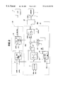
- FIG. 2 is a block diagram explaining the improved integrated driving-torque control in which electronic engine power output control (achieved by virtue of an electronically-controlled throttle 5 plus throttle motor 4 ) is integrated into automatic shifting control (achieved by virtue of a hydraulic actuator unit 12 ).
- FIG. 3 is a required axle-driveshaft driving-torque characteristic map illustrating the relationship among the vehicle speed (VSP), the required driving torque (T o *), and the accelerator pedal depression amount (APS).
- VSP vehicle speed
- T o * required driving torque
- APS accelerator pedal depression amount
- FIG. 4 shows a speed-ratio (e) versus torque-ratio (t) characteristic curve a in case that the releasable coupling device is a torque converter (preferably a lock-up torque converter).
- the integrated driving-torque control system of the invention is exemplified in an automotive vehicle equipped with an inline four-cylinder gasoline engine 1 mated to a continuously variable automatic transmission (CVT) combined with a torque converter 6 .
- a belt-type continuously variable automatic transmission 2 is used as the CVT.
- Engine power output or output torque from the engine 1 can be electronically controlled, irrespective of depression of the accelerator pedal, as detailed herebelow.
- the engine 1 is equipped with an electronically-controlled throttle 5 whose opening (i.e., the flow rate of intake air entering each intake-valve port) is electronically controlled by means of a so-called throttle motor 4 , independently of a depression amount or an operating amount of an accelerator pedal operated by the driver.
- the throttle motor 4 usually comprises a stepper motor (also known as a “stepping motor” or a “step-servo motor”).
- the throttle motor 4 of the electronically-controlled throttle 5 is connected via a signal line to the output interface (or a drive circuit) of an electronic control module (ECM) or an electronic control unit (ECU) 13 , so that the angular steps or essentially uniform angular movements of the motor 4 can be obtained electro-magnetically depending on a control signal (or a drive signal) which is output from the output interface of the control unit 13 and indicative of a desired throttle opening TVO*.
- ECM electronice control module
- ECU electronic control unit
- the belt-type continuously variable transmission 6 has primary and secondary—driving and driven—pulleys 7 and 8 whose effective diameters are continuously changeable.
- the primary pulley is often called an “input pulley”, whereas the secondary pulley is often called an “output pulley”.
- the belt-type CVT has a segmented steel belt 9 wound on both the primary and secondary pulleys 7 and 8 .
- the output shaft (i.e., crankshaft) of the engine 1 is connected to the primary pulley 7 via a torque-converter (preferably a so-called lock-up torque converter) or an electromagnetic clutch, and therefore power output of the engine 1 is transmitted to the secondary pulley by the segmented steel belt 9 .
- the secondary pulley 8 has a drive-connection with a differential 11 via a final gear set 10 to transmit driving torque (or positive wheel torque) to axle driveshafts or drive wheels.
- a line pressure is suitably compensated or regulated as a secondary pulley actuation pressure P sec by means of a line-pressure control system involving a plurality of valves. Then, the regulated line pressure is fed into a driven-pulley hydraulic actuator included in a hydraulic actuator unit or a hydraulic modulator unit 12 .
- the primary pulley 7 comprises a stationary conical flange and an adjustable conical flange or a movable flange to form a V-shaped groove and consequently to form a variable width pulley 7 .
- the movable flange of the primary pulley is slidably connected onto the central shaft of the stationary flange by means of linear ball bearing splines (not shown for the purpose of illustrative simplicity), in a manner so as to prevent relative rotation of the movable flange to the stationary flange and at the same time to permit axial sliding movement of the movable flange relative to the stationary flange.
- the secondary pulley 8 comprises a stationary conical flange and an adjustable conical flange or a movable flange to form a V-shaped groove and to form a variable width pulley 8 .
- the movable flange of the secondary pulley 8 is slidably connected onto the central shaft of the stationary flange by means of linear ball bearing splines (not shown), in a manner so as to prevent relative rotation of the movable flange to the stationary flange and at the same time to permit axial sliding movement of the movable flange relative to the stationary flange.
- a so-called speed-change control pressure is produced by further regulating the properly regulated line pressure at a designated pressure level.
- the speed-change control pressure often called a “primary pressure”, is fed via a control pressure line into a driving-pulley hydraulic actuator included in the hydraulic actuator unit 12 as a primary pulley actuation pressure P pri .
- the speed-change control pressure or the primary pulley actuation pressure P pri is applied to the movable flange of the primary pulley 7 , so that the movable flange moves toward the stationary flange, whereas the compensated line pressure, that is, the secondary pulley actuation pressure P sec , is applied to the movable flange of the secondary pulley 8 , so that the movable flange moves toward the stationary flange.
- the axial position of the primary-pulley movable flange is controlled by the regulated line pressure in a primary pulley actuation cylinder of the driving-pulley hydraulic actuator.
- the axial position of the secondary-pulley movable flange is controlled by way of the coil spring bias plus speed-change control pressure in a smaller-diameter secondary pulley actuation cylinder of the driven-pulley hydraulic actuator.
- a pressure-receiving area of the primary-pulley movable flange receiving the primary pulley actuation pressure P pri is designed to be two-times greater than that of the secondary-pulley movable flange receiving the secondary pulley actuation pressure P sec .
- the effective diameters of the primary and secondary pulleys 7 and 8 are continuously changeable in response to the differential pressure between the secondary pulley actuation pressure (simply a secondary pressure) P sec and the primary pulley actuation pressure (simply a primary pressure) P pri .
- the speed-change ratio or the transmission ratio of the CVT can be continuously varied within certain limits, depending on the previously-noted differential pressure.
- the differential pressure between the primary and secondary pressures is determined by a control signal value or a control command which is output from the output interface of the ECU 13 to the hydraulic actuator unit 12 and representative of a desired transmission ratio i*.
- both of the primary-pulley movable flange and the secondary-pulley movable flange can shift depending on the primary pressure P pri and the secondary pressure P sec output from the hydraulic actuator unit 12 whose output pressures (P pri , P sec ) are modulated in response to the control signal reflecting the desired transmission ratio i*.
- This enables the actual transmission ratio of the CVT 2 to be steplessly adjusted or feedback-controlled toward the desired transmission ratio i*.
- the previously-noted desired throttle opening TVO* of the electronically-controlled throttle 5 and the desired transmission ratio i* are arithmetically calculated by the processor (CPU or MPU) containing an arithmetic and logic section employed in the ECU 13 .
- the arithmetic calculations for the control signal values TVO* and i* will be hereinbelow described in detail by reference to data and control signal flow indicated in the form of the block diagram shown in FIG. 2 .
- the input interface of the control unit 13 receives various signals (APS, N e , TVO, N i , N o , VSP) from engine/vehicle sensors, namely an accelerator position sensor 14 , a crank angle sensor 15 , a throttle opening sensor 16 , a transmission input-shaft speed sensor 17 , a transmission output-shaft speed sensor 18 , and a vehicle speed sensor 19 .
- the accelerator position sensor 14 is provided to detect a depression amount of an accelerator pedal 3 (or an angular position of the accelerator pedal or an operating amount of the accelerator pedal).
- the crank angle sensor 15 is provided to detect engine speed N e of the engine 1 .
- the engine-speed indicative signal from the crank angle sensor 15 actually corresponds to an input shaft rotational speed of the torque converter 6 .
- the throttle opening sensor 16 is provided to generate a throttle-opening sensor signal indicative of a throttle opening TVO which is generally defined as a ratio of an actual throttle angle of the throttle 5 to a throttle angle obtained at wide open throttle.
- the transmission input-shaft speed sensor (or the primary-pulley rotational speed sensor) 17 is generally located near the flanged portion of the primary pulley 7 , to detect the transmission input-shaft rotational speed N i .
- the transmission input-shaft rotational speed N i detected by the sensor 17 corresponds to an output-shaft rotational speed of the torque converter 6 .
- the transmission output-shaft speed sensor (or the secondary-pulley rotational speed sensor) 18 is generally located near the flanged portion of the secondary pulley 8 to detect the transmission output-shaft rotational speed N o .
- the vehicle speed sensor 19 is provided to detect the vehicle speed VSP. As can be seen from the block diagram of FIG.
- the control unit 13 in order for the driving-torque control system of the embodiment to execute the integrated driving-torque control (that is, a combination of the automatic speed-change control for the CVT 2 and the throttle opening control for the engine 1 equipped with the electronically-controlled throttle 5 ), the control unit 13 , first of all, extracts the input informational data, namely the more recent vehicle speed data VSP, the more recent accelerator depression amount data APS, the more recent engine speed date N e , the more up-to-date transmission input-shaft speed data N i , and the more up-to-date transmission output-shaft speed data N o .
- FIG. 2 shows a block diagram of the system of the embodiment, necessary for estimating or arithmetically calculating the desired transmission ratio i* for the automatic shifting control of the CVT 2 , and for estimating or arithmetically calculating the desired engine output torque TVO* for the electronic engine power output control of the engine 1 with the electronically-controlled throttle 5 .
- reference sign 30 denotes a desired transmission ratio (i*) arithmetic-calculation block or a desired transmission ratio arithmetic-calculation circuitry
- reference sign 40 denotes a desired engine output torque (TVO*) arithmetic-calculation block or a desired engine output torque arithmetic-calculation circuitry.
- the desired transmission ratio arithmetic-calculation block 30 comprises a required axle-driveshaft driving torque arithmetic-calculation section (or a required axle-driveshaft driving torque arithmetic-calculation circuitry) 31 and a desired transmission ratio arithmetic-calculation section (or a desired transmission ratio arithmetic-calculation circuitry) 32 .
- the required axle-driveshaft driving torque arithmetic-calculation section 31 is designed to retrieve a required axle-driveshaft driving torque (simply a required driving torque T o *) on the basis of both the accelerator depression amount data APS from the sensor 14 and the vehicle speed data VSP from the sensor 19 , from the predetermined or preprogrammed required axle-driveshaft driving-torque characteristic map shown in FIG. 3 .
- the desired transmission ratio arithmetic-calculation section 32 retrieves a desired transmission input-shaft rotational speed N i * on the basis of both the required driving torque T o * and the vehicle speed data VSP, from a predetermined or preprogrammed desired transmission ratio (i*) characteristic map showing the relationship among the vehicle speed VSP, the required driving torque T o *, and the desired transmission input-shaft rotational speed N i *.
- a predetermined or preprogrammed desired transmission ratio (i*) characteristic map showing the relationship among the vehicle speed VSP, the required driving torque T o *, and the desired transmission input-shaft rotational speed N i *.
- the output interface of the control unit 13 generates a control signal or a drive signal corresponding to the desired transmission ratio i* to the hydraulic actuator unit 12 of the CVT 2 to operate the driving-pulley hydraulic actuator and the driven-pulley hydraulic actuator both included in the hydraulic actuator unit 12 , so that the transmission input-shaft rotational speed is adjusted toward the desired value N i *.
- the ECU 13 containing the input/output interface and the desired transmission ratio arithmetic-calculation circuitry 30 functions as an automatic shifting control section for the CVT 2 .
- the desired engine output torque (TVO*) arithmetic-calculation block 40 see the lower block indicated by the broken line of FIG. 2 ).
- the desired engine output torque arithmetic-calculation block 40 comprises a speed-ratio arithmetic-calculation section 41 , a torque-ratio arithmetic-calculation section 42 , a transmission-ratio arithmetic-calculation section 43 , a first divider 44 , a second divider 45 , a second desired engine-output-torque arithmetic-calculation section 46 , and a desired engine-output-torque selector 47 .
- the torque converter 6 is exemplified as a releasable coupling device, and thus the torque-ratio arithmetic-calculation section 42 retrieves a torque ratio t on the basis of the speed ratio e calculated by the arithmetic-calculation section 41 , utilizing the predetermined or preprogrammed speed-ratio versus torque-ratio characteristic curve a suitable for the torque-converter-equipped engine.
- the first divider 44 is designed to derive a desired input-shaft torque (T o */t) of the CVT 2 by dividing the required axle-driveshaft driving torque T o * by the torque ratio t.
- the divider pair ( 44 , 45 ) can be referred to as a “first desired engine-output-torque arithmetic-calculation section” or a “first desired engine-output-torque arithmetic-calculation circuitry”.
- the second desired engine-output-torque arithmetic-calculation section (or the second desired engine-output-torque arithmetic-calculation circuitry) 46 is provided to retrieve a second desired engine output torque T e2 * on the basis of both the accelerator depression amount data APS and the engine speed data N e , from a predetermined or preprogrammed accelerator-pedal-position dependent desired engine-output-torque characteristic map shown in the second desired engine-output-torque arithmetic-calculation section 46 of FIG. 2 .
- the desired engine-output-torque selector 47 is also provided to select the first desired engine output torque value T e1 * out of the first and second desired engine output torque values T e1 * and T e2 *, and to generate an output signal indicative of the first desired engine output torque T e1 * as a final desired engine output torque T e *, when the vehicle speed VSP is equal to or greater than a preset vehicle speed or a predetermined vehicle speed threshold VSP s .
- the desired engine-output-torque selector 47 selects the second desired engine output torque value T e2 * out of the first and second desired engine output torque values T e1 * and T e2 *, and to generate an output signal indicative of the second desired engine output torque T e2 * as the final desired engine output torque T e *.
- the ECU 13 containing the input/output interface and the desired engine-output-torque arithmetic-calculation circuitry 40 also functions as an electronic engine power output control section for the electronically-controlled engine 1 . From the viewpoint of optimal setting of the predetermined vehicle speed threshold VSP S , as seen in FIG.
- the vehicle speed threshold VSP S is preset or preprogrammed to a lower limit of a vehicle speed range within which there is a less rate of change in the desired engine output torque (the final engine output torque) T e * with respect to the vehicle speed VSP, and thus there is no or less problem (no or less risk) of the reduced accuracy of driving-torque control, caused by fluctuations in the required axle-driveshaft driving torque T o *, that is, deterioration of driveability of the vehicle, occurring owing to an error in detection of the vehicle speed VSP.
- Informational data signal indicative of the previously-discussed desired engine output torque T e *, selected or determined by the desired engine output torque selector 47 is input into a desired throttle-opening arithmetic-calculation section 49 .
- the throttle-opening arithmetic-calculation section 49 computes a desired throttle opening TVO* required to produce the desired engine output torque T e *, on the basis of both the desired engine output torque T e * selected by the section 47 and the engine speed data N e .
- the throttle-opening arithmetic-calculation section 49 generates an output signal (a control signal or a drive signal corresponding to the desired throttle opening TVO*) to operate the throttle motor 4 , so that the opening of the electronically-controlled throttle 5 is adjusted to the desired throttle opening TVO*.
- the required axle-driveshaft driving torque T o * is arithmetically calculated from both the accelerator depression amount data APS and the vehicle speed data VSP, and the desired transmission ratio i* is derived from both the required axle-driveshaft driving torque T o * and the vehicle speed VSP. Then, the automatic shifting control of the CVT 2 is made so that the actual transmission ratio of the CVT is adjusted toward the desired transmission ratio i*.
- the electronic engine output torque control (or the electronic engine power output control of the engine 1 or the electronic throttle opening control of the throttle 5 ) is executed in such a manner as to generate the first desired engine output torque T e1 * corresponding to the required axle-driveshaft driving torque T o *.
- the electronic engine power output control of the engine 1 and the automatic shifting control of the CVT 2 it is possible to achieve the designated integrated driving-torque control that the required axle-driveshaft driving torque T o * is realized with the lowest possible fuel consumption at the vehicle speed indicative information data sampled.
- the electronic engine output torque control is executed in such a manner as to generate the second desired engine output torque T e2 * corresponding to the accelerator depression amount data APS, in lieu of the first desired engine output torque T e1 .*.
- the electronic engine power output control is executed so that the actual engine output torque is adjusted toward the accelerator-pedal depression (APS) dependent second desired engine output torque value T e2 *.
- APS accelerator-pedal depression
- the electronic engine power output control can be unaffected by an error in detection of the vehicle speed VSP in the low-speed range, thus avoiding the problem of deteriorated driveability even in the low-speed range within which a rate of change of the required axle-driveshaft driving torque T o * with respect to the vehicle speed VSP is preset to a comparatively great value (see a relatively steep gradient of the required axle-driveshaft driving-torque characteristic curve of FIG. 3 in the low-speed range).
- the electronic engine power output control is attained by electronically controlling or adjusting the throttle opening TVO of the throttle 5 .
- Such an electronic engine power output control based on the electronic throttle-opening control is useful in a gasoline engine mated to a CVT.
- the integrated driving-torque control system of the invention is applicable to a diesel engine with an electronic fuel injection system.
- the electronic diesel-engine power output control can be attained by electronically controlling or adjusting a fuel injection amount in place of the throttle opening TVO, since the diesel-engine output torque value is in proportion to the fuel injection amount.
- the desired engine-output-torque selector 47 is designed to realize a smooth transition between the first and second desired engine output torque values T e1 * and T e2 * in time series, as discussed hereunder.
- the desired engine-output-torque selector 47 operates to switch the desired engine output torque T e * from the second desired engine output torque T e2 * to the first desired engine output torque T e1 * in time series, in accordance with the following expression.
- T e * (1 ⁇ K ) ⁇ T e2 *+K ⁇ T e1 *
- K is a coefficient varying (increasing) linearly from 0 to 1 for a predetermined period of time.
- the desired engine-output-torque selector 47 operates to switch the desired engine output torque T e * from the first desired engine output torque T e1 * to the second desired engine output torque T e2 * in time series, in accordance with the following expression.
- T e * (1 ⁇ K ) ⁇ T e1 *+K ⁇ T e2 *
- the desired engine-output-torque selector 47 comprises a comparator for comparing the vehicle speed (VSP) with the predetermined vehicle speed threshold (VSP S ) and a gain controller smoothly switching between the first desired engine output torque (T e1 *) and the second desired engine output torque (T e2 *) for the predetermined period of time.
- the gain controller operates to linearly increase the first desired engine output torque (T e1 *) with a control gain K increasing linearly from 0 to 1 for the predetermined period of time and operates to linearly decrease the second desired engine output torque (T e2 *) with a control gain (1 ⁇ K) decreasing linearly from 1 to 0 for the predetermined period of time.
- the gain controller operates to linearly decrease the first desired engine output torque (T e1 *) with the control gain (1 ⁇ K) decreasing linearly from 1 to 0 for the predetermined period of time and operates to linearly increase the second desired engine output torque (T e2 *) with the control gain (K) increasing linearly from 0 to 1 for the predetermined period of time.
- the desired engine output torque selected by the selector 47 is obtained as the sum of the first desired engine output torque (T e1 *) and the second desired engine output torque (T e2 *) linearly varying for the predetermined period of time.
- the desired engine-output-torque selector 47 can ensure more smooth switching between the first and second desired engine output torque values T e1 * and T e2 * for the previously-noted predetermined time period, irrespective of the direction of transition from the first desired engine output torque values T e1 * to T e2 * and vice versa, thus avoiding undesirable power train shock occurring due to the torque difference between the first and second desired engine output torque values T e1 * and T e2 *.
Landscapes
- Engineering & Computer Science (AREA)
- Chemical & Material Sciences (AREA)
- Combustion & Propulsion (AREA)
- Mechanical Engineering (AREA)
- Transportation (AREA)
- General Engineering & Computer Science (AREA)
- Automation & Control Theory (AREA)
- Control Of Transmission Device (AREA)
- Control Of Driving Devices And Active Controlling Of Vehicle (AREA)
- Control Of Vehicle Engines Or Engines For Specific Uses (AREA)
- Electrical Control Of Air Or Fuel Supplied To Internal-Combustion Engine (AREA)
Applications Claiming Priority (2)
| Application Number | Priority Date | Filing Date | Title |
|---|---|---|---|
| JP15612698A JP3438589B2 (ja) | 1998-06-04 | 1998-06-04 | 車両の駆動力制御装置 |
| JP10-156126 | 1998-06-04 |
Publications (1)
| Publication Number | Publication Date |
|---|---|
| US6181020B1 true US6181020B1 (en) | 2001-01-30 |
Family
ID=15620903
Family Applications (1)
| Application Number | Title | Priority Date | Filing Date |
|---|---|---|---|
| US09/325,795 Expired - Lifetime US6181020B1 (en) | 1998-06-04 | 1999-06-04 | Integrated driving torque control system for automotive vehicles with continuously variable automatic transmission |
Country Status (3)
| Country | Link |
|---|---|
| US (1) | US6181020B1 (ja) |
| JP (1) | JP3438589B2 (ja) |
| DE (1) | DE19925414B4 (ja) |
Cited By (43)
| Publication number | Priority date | Publication date | Assignee | Title |
|---|---|---|---|---|
| US6332859B1 (en) * | 1999-05-17 | 2001-12-25 | Mitsubishi Jidosha Kogyo Kabushiki Kaisha | Control system and method for continuously variable transmission |
| US20020037788A1 (en) * | 2000-09-26 | 2002-03-28 | Yoshichika Hagiwara | Control device for a continuously variable transmission |
| US6436003B1 (en) * | 1999-08-24 | 2002-08-20 | General Motors Corporation | Process for controlling a CVT installed in the power train of a motor vehicle |
| US6482122B2 (en) * | 2000-05-22 | 2002-11-19 | Jatco Transtechnology Ltd. | Driving force control device |
| US20030022753A1 (en) * | 2001-07-26 | 2003-01-30 | Toyota Jidosha Kabushiki Kaisha | Control system and method for vehicle having continuously variable transmission |
| FR2830216A1 (fr) * | 2001-09-29 | 2003-04-04 | Bosch Gmbh Robert | Procede et dispositif pour la mise en oeuvre d'une unite d'entrainement d'un vehicule |
| US6546324B1 (en) * | 2001-08-22 | 2003-04-08 | Delphi Technologies, Inc. | System and method incorporating dynamic feedforward for integrated control of motor vehicle steering and braking |
| US6558291B1 (en) * | 1999-04-16 | 2003-05-06 | Luk Lamellen Und Kupplungsbau Beteiligungs Kg | Motor vehicle |
| US6567731B2 (en) * | 2001-08-22 | 2003-05-20 | Delphi Technologies, Inc. | System and method incorporating feedforward for motor vehicle chassis control |
| US20030094816A1 (en) * | 2001-03-06 | 2003-05-22 | Isamu Kazama | Hybrid vehicle control system and control method |
| US6663532B1 (en) | 1999-09-20 | 2003-12-16 | Transmisiones Tsp, S. A., De, C.V. | Dual strategy control for a toroidal drive type continuously variable transmission |
| US6819996B2 (en) | 2002-12-30 | 2004-11-16 | Caterpillar Inc | Control system for operating a vehicle within a limited engine speed range |
| US6837323B2 (en) | 2001-06-18 | 2005-01-04 | Visteon Global Technologies Inc. | Variable shift schedule control |
| US20050171669A1 (en) * | 2004-02-03 | 2005-08-04 | Denso Corporation | Vehicle control system ensuring stability of control |
| US20060038406A1 (en) * | 2004-08-20 | 2006-02-23 | Hitachi, Ltd. | Power supply system for vehicle |
| US7288047B1 (en) * | 2005-06-10 | 2007-10-30 | Polaris Industries Inc. | Engine and transmission control system and method for a motorized vehicle |
| US20070288151A1 (en) * | 2006-06-08 | 2007-12-13 | Nissan Motor Co., Ltd. | Engine output control apparatus of power train |
| US20070284844A1 (en) * | 2006-03-14 | 2007-12-13 | Miles David M | Wheel chair |
| US20080294318A1 (en) * | 2007-05-22 | 2008-11-27 | Caterpillar Inc. | Feedback adjustment for open-loop torque control map |
| US20080300103A1 (en) * | 2007-05-31 | 2008-12-04 | Caterpillar Inc. | Open-loop torque control with closed-loop feedback |
| US20080315559A1 (en) * | 2005-03-07 | 2008-12-25 | Iseki & Co., Ltd. | Work Vehicle |
| EP1403563A3 (en) * | 2002-09-30 | 2009-04-01 | JATCO Ltd | Control for belt-type continuously-variable transmission |
| US20090088936A1 (en) * | 2007-09-28 | 2009-04-02 | Caterpillar Inc. | CVT control system having variable power source speed |
| US20090247356A1 (en) * | 2005-10-14 | 2009-10-01 | Yasushi Hatanaka | Engine Revolutions Control Device of Working Vehicle and Method |
| US20090287376A1 (en) * | 2006-12-07 | 2009-11-19 | Toyota Jidosha Kabushiki Kaisha | Vehicle Control Device |
| US20100250127A1 (en) * | 2007-10-26 | 2010-09-30 | Geert Hilbrandie | Method of processing positioning data |
| US20100268434A1 (en) * | 2008-04-23 | 2010-10-21 | Ludger Hugenroth | Method of operation for an internal combustion engine |
| US20110196588A1 (en) * | 2008-10-23 | 2011-08-11 | Zf Friedrichshafen Ag | Method for engaging a torque converter lock-up clutch in a power transmission of a mobile machine |
| US20110197696A1 (en) * | 2008-10-23 | 2011-08-18 | Zf Friedrichshafen Ag | Method for controlling a lock-up clutch of a hydrodynamic torque converter |
| US20110197695A1 (en) * | 2008-10-23 | 2011-08-18 | Zf Friedrichshafen Ag | Method for the operation of a clutch of a hydrodynamic torque converter |
| US20110202244A1 (en) * | 2008-10-23 | 2011-08-18 | Zf Friedrichshafen Ag | Method for operating the torque converter lock-up clutch in a power transmission of a mobile machine comprising at least one hydraulically actuated lifting device |
| US20110197694A1 (en) * | 2008-10-23 | 2011-08-18 | Zf Friedrichshafen Ag | Method for reversing the direction of travel of a vehicle |
| US20110203892A1 (en) * | 2008-10-23 | 2011-08-25 | Zf Friedrichshafen Ag | Method for actuating a clutch of a hydrodynamic torque converter |
| US20150088391A1 (en) * | 2013-09-20 | 2015-03-26 | Toyota Jidosha Kabushiki Kaisha | Gear shifting control system of vehicle continuously-variable transmission |
| US20150224993A1 (en) * | 2012-09-19 | 2015-08-13 | Nissan Motor Co., Ltd. | Vehicle control device and vehicle control method |
| EP2927069A4 (en) * | 2012-11-27 | 2016-08-31 | Nissan Motor | VEHICLE CONTROL APPARATUS, AND METHOD OF CONTROLLING THE SAME |
| US9545929B1 (en) * | 2015-10-19 | 2017-01-17 | GM Global Technology Operations LLC | Method and apparatus to control a continuously variable transmission |
| CN106385205A (zh) * | 2016-09-21 | 2017-02-08 | 珠海格力节能环保制冷技术研究中心有限公司 | 霍尔永磁同步电机的控制方法及装置 |
| CN106894901A (zh) * | 2015-12-21 | 2017-06-27 | 广州汽车集团股份有限公司 | 一种发动机功率控制方法及系统 |
| US9830815B2 (en) | 2010-11-08 | 2017-11-28 | Tomtom Navigation B.V. | Navigation apparatus and method |
| US10107633B2 (en) | 2013-04-26 | 2018-10-23 | Tomtom Traffic B.V. | Methods and systems for providing information indicative of a recommended navigable stretch |
| CN110733480A (zh) * | 2019-10-18 | 2020-01-31 | 上海格陆博实业有限公司 | 一种基于反馈增量pid控制的刹车控制系统下层控制器 |
| CN114545905A (zh) * | 2022-02-25 | 2022-05-27 | 奇瑞新能源汽车股份有限公司 | 电动汽车的动力速比逻辑控制模拟方法、装置及设备 |
Families Citing this family (2)
| Publication number | Priority date | Publication date | Assignee | Title |
|---|---|---|---|---|
| JP2001322456A (ja) * | 2000-05-12 | 2001-11-20 | Mitsubishi Electric Corp | 自動変速機付きエンジンの制御装置 |
| US9670857B2 (en) * | 2015-08-17 | 2017-06-06 | GM Global Technology Operations LLC | Torque control of a power-plant for launching a vehicle with a manual transmission |
Citations (10)
| Publication number | Priority date | Publication date | Assignee | Title |
|---|---|---|---|---|
| JPS62110536A (ja) | 1985-11-06 | 1987-05-21 | Toyota Motor Corp | 車両駆動系の制御装置 |
| JPH07172217A (ja) | 1993-12-22 | 1995-07-11 | Nissan Motor Co Ltd | 車両の駆動力制御装置 |
| US5947861A (en) * | 1995-11-07 | 1999-09-07 | Mazda Motor Corporation | Control system for a continuously variable transmission capable of varying the gear ratio in a continuous or step-wise manner |
| US6054844A (en) * | 1998-04-21 | 2000-04-25 | The Regents Of The University Of California | Control method and apparatus for internal combustion engine electric hybrid vehicles |
| US6055474A (en) * | 1997-04-08 | 2000-04-25 | Nissan Motor Co., Ltd. | Speed change ratio controller for continuously variable transmission |
| US6063004A (en) * | 1996-11-29 | 2000-05-16 | Hitachi, Ltd. | Control apparatus and control method for an engine powertrain of a vehicle |
| US6066070A (en) * | 1998-04-28 | 2000-05-23 | Toyota Jidosha Kabushiki Kaisha | Control system of vehicle having continuously variable transmission |
| US6083138A (en) * | 1998-03-20 | 2000-07-04 | Nissan Motor Co., Ltd. | Hybrid drive control system for vehicle |
| US6086507A (en) * | 1997-08-06 | 2000-07-11 | Robert Bosch Gmbh | Device and method for adjusting the ratio of transmission in a CVT |
| US6090007A (en) * | 1998-03-20 | 2000-07-18 | Nissan Motor Co., Ltd. | Hybrid vehicle drive force control device and control method |
Family Cites Families (1)
| Publication number | Priority date | Publication date | Assignee | Title |
|---|---|---|---|---|
| DE4223967A1 (de) * | 1992-07-21 | 1994-01-27 | Bosch Gmbh Robert | Einrichtung zur Einstellung eines Getriebe-Abtriebsmoments oder einer Getriebe-Ausgangsleistung bei Fahrzeugen mit kontinuierlich verstellbarem Getriebe (CVT) |
-
1998
- 1998-06-04 JP JP15612698A patent/JP3438589B2/ja not_active Expired - Lifetime
-
1999
- 1999-06-02 DE DE19925414A patent/DE19925414B4/de not_active Expired - Lifetime
- 1999-06-04 US US09/325,795 patent/US6181020B1/en not_active Expired - Lifetime
Patent Citations (10)
| Publication number | Priority date | Publication date | Assignee | Title |
|---|---|---|---|---|
| JPS62110536A (ja) | 1985-11-06 | 1987-05-21 | Toyota Motor Corp | 車両駆動系の制御装置 |
| JPH07172217A (ja) | 1993-12-22 | 1995-07-11 | Nissan Motor Co Ltd | 車両の駆動力制御装置 |
| US5947861A (en) * | 1995-11-07 | 1999-09-07 | Mazda Motor Corporation | Control system for a continuously variable transmission capable of varying the gear ratio in a continuous or step-wise manner |
| US6063004A (en) * | 1996-11-29 | 2000-05-16 | Hitachi, Ltd. | Control apparatus and control method for an engine powertrain of a vehicle |
| US6055474A (en) * | 1997-04-08 | 2000-04-25 | Nissan Motor Co., Ltd. | Speed change ratio controller for continuously variable transmission |
| US6086507A (en) * | 1997-08-06 | 2000-07-11 | Robert Bosch Gmbh | Device and method for adjusting the ratio of transmission in a CVT |
| US6083138A (en) * | 1998-03-20 | 2000-07-04 | Nissan Motor Co., Ltd. | Hybrid drive control system for vehicle |
| US6090007A (en) * | 1998-03-20 | 2000-07-18 | Nissan Motor Co., Ltd. | Hybrid vehicle drive force control device and control method |
| US6054844A (en) * | 1998-04-21 | 2000-04-25 | The Regents Of The University Of California | Control method and apparatus for internal combustion engine electric hybrid vehicles |
| US6066070A (en) * | 1998-04-28 | 2000-05-23 | Toyota Jidosha Kabushiki Kaisha | Control system of vehicle having continuously variable transmission |
Cited By (84)
| Publication number | Priority date | Publication date | Assignee | Title |
|---|---|---|---|---|
| US6558291B1 (en) * | 1999-04-16 | 2003-05-06 | Luk Lamellen Und Kupplungsbau Beteiligungs Kg | Motor vehicle |
| US6332859B1 (en) * | 1999-05-17 | 2001-12-25 | Mitsubishi Jidosha Kogyo Kabushiki Kaisha | Control system and method for continuously variable transmission |
| US6436003B1 (en) * | 1999-08-24 | 2002-08-20 | General Motors Corporation | Process for controlling a CVT installed in the power train of a motor vehicle |
| US6663532B1 (en) | 1999-09-20 | 2003-12-16 | Transmisiones Tsp, S. A., De, C.V. | Dual strategy control for a toroidal drive type continuously variable transmission |
| US20040038772A1 (en) * | 1999-09-20 | 2004-02-26 | Mcindoe Gordon M. | Dual strategy control for a toroidal drive type continuously variable transmission |
| US6482122B2 (en) * | 2000-05-22 | 2002-11-19 | Jatco Transtechnology Ltd. | Driving force control device |
| US20020037788A1 (en) * | 2000-09-26 | 2002-03-28 | Yoshichika Hagiwara | Control device for a continuously variable transmission |
| US6695742B2 (en) * | 2000-09-26 | 2004-02-24 | Jatco Transtechnology Ltd. | Control device for a continuously variable transmission |
| US6891279B2 (en) * | 2001-03-06 | 2005-05-10 | Nissan Motor Co., Ltd. | Vehicle control system and control method |
| US20030094816A1 (en) * | 2001-03-06 | 2003-05-22 | Isamu Kazama | Hybrid vehicle control system and control method |
| US6837323B2 (en) | 2001-06-18 | 2005-01-04 | Visteon Global Technologies Inc. | Variable shift schedule control |
| US6726594B2 (en) * | 2001-07-26 | 2004-04-27 | Toyota Jidosha Kabushiki Kaisha | Control system and method for vehicle having continuously variable transmission |
| US20030022753A1 (en) * | 2001-07-26 | 2003-01-30 | Toyota Jidosha Kabushiki Kaisha | Control system and method for vehicle having continuously variable transmission |
| US6546324B1 (en) * | 2001-08-22 | 2003-04-08 | Delphi Technologies, Inc. | System and method incorporating dynamic feedforward for integrated control of motor vehicle steering and braking |
| US6567731B2 (en) * | 2001-08-22 | 2003-05-20 | Delphi Technologies, Inc. | System and method incorporating feedforward for motor vehicle chassis control |
| FR2830216A1 (fr) * | 2001-09-29 | 2003-04-04 | Bosch Gmbh Robert | Procede et dispositif pour la mise en oeuvre d'une unite d'entrainement d'un vehicule |
| EP1403563A3 (en) * | 2002-09-30 | 2009-04-01 | JATCO Ltd | Control for belt-type continuously-variable transmission |
| US6819996B2 (en) | 2002-12-30 | 2004-11-16 | Caterpillar Inc | Control system for operating a vehicle within a limited engine speed range |
| US20050171669A1 (en) * | 2004-02-03 | 2005-08-04 | Denso Corporation | Vehicle control system ensuring stability of control |
| US7606649B2 (en) * | 2004-02-03 | 2009-10-20 | Denso Corporation | Vehicle control system ensuring stability of control |
| US20060038406A1 (en) * | 2004-08-20 | 2006-02-23 | Hitachi, Ltd. | Power supply system for vehicle |
| US7215034B2 (en) * | 2004-08-20 | 2007-05-08 | Hitachi, Ltd. | Power supply system for vehicle |
| US20080315559A1 (en) * | 2005-03-07 | 2008-12-25 | Iseki & Co., Ltd. | Work Vehicle |
| US7832520B2 (en) * | 2005-03-07 | 2010-11-16 | Iseki & Co., Ltd. | Work vehicle |
| US7288047B1 (en) * | 2005-06-10 | 2007-10-30 | Polaris Industries Inc. | Engine and transmission control system and method for a motorized vehicle |
| US20090247356A1 (en) * | 2005-10-14 | 2009-10-01 | Yasushi Hatanaka | Engine Revolutions Control Device of Working Vehicle and Method |
| US8152690B2 (en) * | 2005-10-14 | 2012-04-10 | Komatsu Ltd. | Engine revolutions control device of working vehicle and method |
| US7770674B2 (en) * | 2006-03-14 | 2010-08-10 | Fallbrook Technologies Inc. | Wheel chair |
| US20070284844A1 (en) * | 2006-03-14 | 2007-12-13 | Miles David M | Wheel chair |
| US20100264620A1 (en) * | 2006-03-14 | 2010-10-21 | Fallbrook Technologies Inc. | Wheelchair |
| US8087482B2 (en) * | 2006-03-14 | 2012-01-03 | Fallbrook Technologies Inc. | Wheelchair |
| US7389176B2 (en) * | 2006-06-08 | 2008-06-17 | Nissan Motor Co., Ltd. | Engine output control apparatus of power train |
| US20070288151A1 (en) * | 2006-06-08 | 2007-12-13 | Nissan Motor Co., Ltd. | Engine output control apparatus of power train |
| US20090287376A1 (en) * | 2006-12-07 | 2009-11-19 | Toyota Jidosha Kabushiki Kaisha | Vehicle Control Device |
| US8401737B2 (en) * | 2006-12-07 | 2013-03-19 | Toyota Jidosha Kabushiki Kaisha | Vehicle control device |
| US7920949B2 (en) | 2007-05-22 | 2011-04-05 | Caterpillar Inc. | Feedback adjustment for open-loop torque control map |
| US20080294318A1 (en) * | 2007-05-22 | 2008-11-27 | Caterpillar Inc. | Feedback adjustment for open-loop torque control map |
| US20080300103A1 (en) * | 2007-05-31 | 2008-12-04 | Caterpillar Inc. | Open-loop torque control with closed-loop feedback |
| US8532889B2 (en) | 2007-05-31 | 2013-09-10 | Caterpillar Inc. | Open-loop torque control with closed-loop feedback |
| US8000863B2 (en) | 2007-05-31 | 2011-08-16 | Caterpillar Inc. | Open-loop torque control with closed-loop feedback |
| US20130245903A1 (en) * | 2007-09-28 | 2013-09-19 | Caterpillar Inc. | Cvt control system having variable power source speed |
| US20090088936A1 (en) * | 2007-09-28 | 2009-04-02 | Caterpillar Inc. | CVT control system having variable power source speed |
| US8554428B2 (en) * | 2007-09-28 | 2013-10-08 | Caterpillar Inc. | CVT control system having variable power source speed |
| US8725366B2 (en) * | 2007-09-28 | 2014-05-13 | Caterpillar Inc. | CVT control system having variable power source speed |
| US20100250127A1 (en) * | 2007-10-26 | 2010-09-30 | Geert Hilbrandie | Method of processing positioning data |
| US9952057B2 (en) | 2007-10-26 | 2018-04-24 | Tomtom Traffic B.V. | Method of processing positioning data |
| US9829332B2 (en) * | 2007-10-26 | 2017-11-28 | Tomtom Navigation B.V. | Method and machine for generating map data and a method and navigation device for determining a route using map data |
| US9297664B2 (en) | 2007-10-26 | 2016-03-29 | Tomtom International B.V. | Method of processing positioning data |
| US8958983B2 (en) | 2007-10-26 | 2015-02-17 | Tomtom International B.V. | Method of processing positioning data |
| US10024677B2 (en) | 2007-10-26 | 2018-07-17 | Tomtom Traffic B.V. | Method of processing positioning data |
| US10024676B2 (en) | 2007-10-26 | 2018-07-17 | Tomtom Traffic B.V. | Method of processing positioning data |
| US20100312472A1 (en) * | 2007-10-26 | 2010-12-09 | Geert Hilbrandie | Method of processing positioning data |
| US20100299055A1 (en) * | 2007-10-26 | 2010-11-25 | Geert Hilbrandie | Method and machine for generating map data and a method and navigation device for determing a route using map data |
| US20100299064A1 (en) * | 2007-10-26 | 2010-11-25 | Geert Hilbrandie | Method of processing positioning data |
| US8068970B2 (en) * | 2008-04-23 | 2011-11-29 | Ludger Hugenroth | Method of operation for an internal combustion engine |
| US20100268434A1 (en) * | 2008-04-23 | 2010-10-21 | Ludger Hugenroth | Method of operation for an internal combustion engine |
| US20110196588A1 (en) * | 2008-10-23 | 2011-08-11 | Zf Friedrichshafen Ag | Method for engaging a torque converter lock-up clutch in a power transmission of a mobile machine |
| US20110202244A1 (en) * | 2008-10-23 | 2011-08-18 | Zf Friedrichshafen Ag | Method for operating the torque converter lock-up clutch in a power transmission of a mobile machine comprising at least one hydraulically actuated lifting device |
| US8491443B2 (en) | 2008-10-23 | 2013-07-23 | Zf Friedrichshafen Ag | Method for controlling a lock-up clutch of a hydrodynamic torque converter |
| US8550960B2 (en) | 2008-10-23 | 2013-10-08 | Zf Friedrichshafen Ag | Method for the operation of a clutch of a hydrodynamic torque converter |
| US8494735B2 (en) | 2008-10-23 | 2013-07-23 | Zf Friedrichshafen Ag | Method for operating the torque converter lock-up clutch in a power transmission of a mobile machine comprising at least one hydraulically actuated lifting device |
| US8726754B2 (en) | 2008-10-23 | 2014-05-20 | Zf Friedrichshafen Ag | Method for reversing the direction of travel of a vehicle |
| CN102187126B (zh) * | 2008-10-23 | 2014-06-25 | Zf腓德烈斯哈芬股份公司 | 用于操作液力变矩器的离合器的方法 |
| CN102187126A (zh) * | 2008-10-23 | 2011-09-14 | Zf腓德烈斯哈芬股份公司 | 用于操作液力变矩器的离合器的方法 |
| US20110197696A1 (en) * | 2008-10-23 | 2011-08-18 | Zf Friedrichshafen Ag | Method for controlling a lock-up clutch of a hydrodynamic torque converter |
| US20110197695A1 (en) * | 2008-10-23 | 2011-08-18 | Zf Friedrichshafen Ag | Method for the operation of a clutch of a hydrodynamic torque converter |
| US8517894B2 (en) | 2008-10-23 | 2013-08-27 | Zf Friedrichshafen Ag | Method for actuating a clutch of a hydrodynamic torque converter |
| US20110203892A1 (en) * | 2008-10-23 | 2011-08-25 | Zf Friedrichshafen Ag | Method for actuating a clutch of a hydrodynamic torque converter |
| US20110197694A1 (en) * | 2008-10-23 | 2011-08-18 | Zf Friedrichshafen Ag | Method for reversing the direction of travel of a vehicle |
| US9830815B2 (en) | 2010-11-08 | 2017-11-28 | Tomtom Navigation B.V. | Navigation apparatus and method |
| US20150224993A1 (en) * | 2012-09-19 | 2015-08-13 | Nissan Motor Co., Ltd. | Vehicle control device and vehicle control method |
| US9376113B2 (en) * | 2012-09-19 | 2016-06-28 | Nissan Motor Co., Ltd. | Vehicle control device and vehicle control method |
| EP2927069A4 (en) * | 2012-11-27 | 2016-08-31 | Nissan Motor | VEHICLE CONTROL APPARATUS, AND METHOD OF CONTROLLING THE SAME |
| US10071740B2 (en) | 2012-11-27 | 2018-09-11 | Nissan Motor Co., Ltd. | Vehicle control apparatus, and method of controlling same |
| US10107633B2 (en) | 2013-04-26 | 2018-10-23 | Tomtom Traffic B.V. | Methods and systems for providing information indicative of a recommended navigable stretch |
| US9150213B2 (en) * | 2013-09-20 | 2015-10-06 | Toyota Jidosha Kabushiki Kaisha | Gear shifting control system of vehicle continuously-variable transmission |
| US20150088391A1 (en) * | 2013-09-20 | 2015-03-26 | Toyota Jidosha Kabushiki Kaisha | Gear shifting control system of vehicle continuously-variable transmission |
| US9545929B1 (en) * | 2015-10-19 | 2017-01-17 | GM Global Technology Operations LLC | Method and apparatus to control a continuously variable transmission |
| CN106894901A (zh) * | 2015-12-21 | 2017-06-27 | 广州汽车集团股份有限公司 | 一种发动机功率控制方法及系统 |
| CN106894901B (zh) * | 2015-12-21 | 2019-10-08 | 广州汽车集团股份有限公司 | 一种发动机功率控制方法及系统 |
| CN106385205A (zh) * | 2016-09-21 | 2017-02-08 | 珠海格力节能环保制冷技术研究中心有限公司 | 霍尔永磁同步电机的控制方法及装置 |
| CN106385205B (zh) * | 2016-09-21 | 2018-12-07 | 珠海格力电器股份有限公司 | 霍尔永磁同步电机的控制方法及装置 |
| CN110733480A (zh) * | 2019-10-18 | 2020-01-31 | 上海格陆博实业有限公司 | 一种基于反馈增量pid控制的刹车控制系统下层控制器 |
| CN114545905A (zh) * | 2022-02-25 | 2022-05-27 | 奇瑞新能源汽车股份有限公司 | 电动汽车的动力速比逻辑控制模拟方法、装置及设备 |
Also Published As
| Publication number | Publication date |
|---|---|
| JP3438589B2 (ja) | 2003-08-18 |
| DE19925414B4 (de) | 2012-01-05 |
| DE19925414A1 (de) | 1999-12-16 |
| JPH11342771A (ja) | 1999-12-14 |
Similar Documents
| Publication | Publication Date | Title |
|---|---|---|
| US6181020B1 (en) | Integrated driving torque control system for automotive vehicles with continuously variable automatic transmission | |
| US6188943B1 (en) | Integrated control system for electronically-controlled engine and automatic transmission | |
| US6157885A (en) | Vehicle motive force control system | |
| JP3754188B2 (ja) | 車両の駆動力制御装置 | |
| US4999774A (en) | Speed ratio control system and method for a continuously variable transmission for a vehicle | |
| US4836056A (en) | Control apparatus for vehicle power transmitting system including continuously variable transmission | |
| US4945483A (en) | Drive control device for vehicle | |
| US6757603B2 (en) | Slippage prevention apparatus of belt-drive continuously variable transmission for automotive vehicle | |
| JPS59217048A (ja) | 車両用無段変速機の制御装置 | |
| JPH07277038A (ja) | 車両制御装置 | |
| US4656587A (en) | Apparatus for controlling continuously variable transmission | |
| US4753133A (en) | Control system for continuously variable transmission in motor vehicle | |
| US6405115B2 (en) | Shift control system for continuously variable transmissions | |
| US10442436B2 (en) | Vehicle driving device | |
| US4880094A (en) | Control system for a clutch for a vehicle | |
| US7445579B2 (en) | System and method of compensating heating performance of continuously-variable-transmission-equipped vehicle | |
| US6485391B2 (en) | Control system for continuously variable automatic transmission | |
| JP3460528B2 (ja) | 車両の駆動力制御装置 | |
| JP3453242B2 (ja) | 車両用自動変速機の制御装置 | |
| JP3157485B2 (ja) | 無段変速機搭載車の変速制御装置 | |
| JP2007132238A (ja) | 車両の発進時エンジン出力制御装置 | |
| JPS58193961A (ja) | 自動車用自動変速装置 | |
| JP3624668B2 (ja) | 車両の駆動力制御装置 | |
| JP4122585B2 (ja) | 車両の駆動力制御装置 | |
| JPH11342770A (ja) | 車両の駆動力制御装置 |
Legal Events
| Date | Code | Title | Description |
|---|---|---|---|
| AS | Assignment |
Owner name: NISSAN MOTOR CO., LTD., JAPAN Free format text: ASSIGNMENT OF ASSIGNORS INTEREST;ASSIGNORS:UCHIDA, MASAAKI;YASUOKA, MASAYUKI;KATAKURA, SHUSAKU;REEL/FRAME:010162/0076;SIGNING DATES FROM 19990719 TO 19990720 |
|
| FEPP | Fee payment procedure |
Free format text: PAYOR NUMBER ASSIGNED (ORIGINAL EVENT CODE: ASPN); ENTITY STATUS OF PATENT OWNER: LARGE ENTITY |
|
| STCF | Information on status: patent grant |
Free format text: PATENTED CASE |
|
| FPAY | Fee payment |
Year of fee payment: 4 |
|
| FPAY | Fee payment |
Year of fee payment: 8 |
|
| FPAY | Fee payment |
Year of fee payment: 12 |