US6176350B1 - Progressive safety gear - Google Patents
Progressive safety gear Download PDFInfo
- Publication number
- US6176350B1 US6176350B1 US09/138,116 US13811698A US6176350B1 US 6176350 B1 US6176350 B1 US 6176350B1 US 13811698 A US13811698 A US 13811698A US 6176350 B1 US6176350 B1 US 6176350B1
- Authority
- US
- United States
- Prior art keywords
- cam
- safety gear
- eccentric
- guide rail
- brake shoe
- Prior art date
- Legal status (The legal status is an assumption and is not a legal conclusion. Google has not performed a legal analysis and makes no representation as to the accuracy of the status listed.)
- Expired - Lifetime
Links
Images


Classifications
-
- B—PERFORMING OPERATIONS; TRANSPORTING
- B66—HOISTING; LIFTING; HAULING
- B66B—ELEVATORS; ESCALATORS OR MOVING WALKWAYS
- B66B5/00—Applications of checking, fault-correcting, or safety devices in elevators
- B66B5/02—Applications of checking, fault-correcting, or safety devices in elevators responsive to abnormal operating conditions
- B66B5/16—Braking or catch devices operating between cars, cages, or skips and fixed guide elements or surfaces in hoistway or well
- B66B5/18—Braking or catch devices operating between cars, cages, or skips and fixed guide elements or surfaces in hoistway or well and applying frictional retarding forces
- B66B5/20—Braking or catch devices operating between cars, cages, or skips and fixed guide elements or surfaces in hoistway or well and applying frictional retarding forces by means of rotatable eccentrically-mounted members
Definitions
- the present invention relates to a progressive safety gear for elevators consisting of a carrier, which is positioned in a transverse direction to the guide rail and which encompasses one guide rail for an elevator car, on which two brake shoes which are positioned one on each side of the guide rail are supported.
- One of the brake shoes functions as a passive brake shoe and the other as an active brake shoe.
- the active brake shoe is supported on an eccentric which is fastened to a cam in such a way that it rotates with it.
- the cam and the eccentric are able to rotate about a common center.
- a progressive safety gear of the type mentioned above is already known from German reference DE 21 39 056.
- this safety gear the blocked governor rope actuates a tripping lever on the safety gear which causes the tensioning eccentric fastened to the positioning eccentric to rotate.
- the tensioning eccentric comes into contact with the guide rail.
- the tensioning eccentric continues to rotate of its own accord due to the friction contact with the guide rail, and the active brake shoe is moved into the braking position via the positioning eccentric.
- the positioning eccentric In the braking position, the positioning eccentric has reached the end position before the greatest distance from the guide rail, because in this position the tensioning eccentric, due to the shape of its external contour, has reduced or lost its friction contact with the guide rail and is therefore no longer caused to rotate.
- a progressive safety gear which also works with an eccentric is the safety gear BFx3 of the East German elevator industry (Liftreport, Issue 5, 1991).
- this progressive safety gear is tripped, two cams with rolling and sliding surfaces are rotated either counter-clockwise or clockwise depending on the direction of travel of the elevator, which causes in the downward travel direction a strong, and in the upward direction a weaker, braking deceleration of the elevator car. Tripping takes place by means of a governor rope passing over a separate pulley which, by transmitting its rotational movement, causes the eccentric to rotate in one direction or the other depending on the direction of travel. If braking takes place in the upward direction the angle of rolling and the radius to the sliding surface in the braking position is smaller than when braking takes place in the downward direction. This results in a different degree of compression of the braking springs and correspondingly the desired different braking forces for the two directions of travel.
- a disadvantage of this device is that the controlling surfaces and the braking surface are on the same component, because of which the braking surface has a relatively small contact surface, which after several trippings as a result of wear can lead under certain circumstances to a reduced braking effect or even to faulty functioning.
- the complete eccentric must then be replaced.
- an elaborate and relatively expensive triggering device is necessary.
- the object of the present invention is therefore to provide a safety gear which can produce in the two directions of travel the different braking effect required, and which does not have the disadvantages described above.
- a progressive safety gear having a console arranged so as to encompass the guide rail and be in a transverse direction to the guide rail, an active brake shoe and a passive brake shoe supported on the console so as to be positioned on one each side of the guide rail, a cam rotatably mounted on the housing, and an eccentric fastened to the cam so that they rotate together between a ready position and braking positions.
- the cam and the eccentric are rotatable about a common center.
- the cam is rotatable in both a clockwise and a counter clockwise direction so that the safety gear can be tripped in both travelling directions.
- the cam is configured so as to remain in contact with the guide rail after a braking operation has taken place so as to permit the cam to be turned backwards, thereby making it possible to release the engaged safety gear by pulling the elevator car out of a position in which it is blocked.
- the progressive safety gear according to the invention is simply constructed, inexpensive to manufacture, and easily to install.
- One aspect of the invention is that the friction contact between the cam and the guide rail which is still present after the safety gear engages makes it easy to release the safety gear.
- the passive brake shoe is able to move freely for a certain distance in a vertical direction during braking and when pulling the safety gear out of its engaged position. By initially reducing the frictional force, this makes it easier to pull the safety gear out of its engaged position.
- angles alpha and beta between the zero point of the point nearest to the guide rail of a cam in the ready position and the upper dead point of the eccentric, or the smaller working angle which is dependent on these two angles up to the point of braking determine, in combination with the shape of the rolling contour of the cam, the ratio between the braking force in the downward direction and in the upward direction.
- the cam can also have an external contour in the shape of a circle, with or without a flat point, which makes it simpler and cheaper to manufacture.
- the circular contour of the cam rolling on the guide rail results in an identical pattern of movement of the cam for both directions of travel, which means that only the rolling angle up to the point of braking (working angle), and to a partial extent the angular position between the cam and the eccentric, determine the ratio between the braking force in the two directions of travel.
- the cam and the eccentric can be produced as a single piece, which is advantageous for manufacturing.
- the cam and the eccentric can also be produced as separate parts whose angle in relation to each other can be adjusted, which makes it possible to influence certain parameters such as, for example, the onset of the braking effect.
- the final position of the safety gear and of the cam when braking takes place is determined without a stopper by a naturally occurring equilibrium between the pressure forces of the active brake shoe and the cam.
- the frictional engagement present between the guide rail and the cam, together with the vertical play of the passive brake shoe, makes it particularly easy to pull the safety gear out of its engaged position by rotating the cam in the reverse direction on the guide rail.
- FIG. 1 is a view of the complete progressive safety gear pursuant to the present invention in the ready position
- FIGS. 2 to 4 show a sequence of functioning as the progressive safety gear engages when travelling in the downward direction
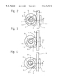
- FIGS. 5 to 7 show a sequence of functioning as the progressive safety gear engages when travelling in the upward direction
- FIG. 8 is a plan view of the single-part actuating element
- FIG. 9 is a cross-section of the single-part actuating element of FIG. 8, along the line IX—IX;
- FIG. 10 is a plan view of the multi-part and adjustable actuating element.
- FIG. 11 is a cross-section of the multi-part and adjustable actuating element of FIG. 10, along the line XI—XI.
- FIG. 1 shows a console 1 to which at the left-hand extremity a thrust plate 3 and on the right-hand side a bearing journal 2 are non-detachably fastened.
- An actuating element 21 is fastened to the bearing journal 2 by means of a plain bearing bush 23 so that the actuating element 21 can rotate.
- the actuating element 21 consists of a larger cam 4 and a smaller eccentric 5 which is fastened to the cam 4 in such a way that it rotates with it.
- the eccentric 5 itself consists of two eccentric disks, which are positioned on the two sides of the cam 4 in the same position relative to each other.
- the cam 4 has a flat point whose mid-point is designated as 4 .
- the flat point 4 . 1 is an important part of the shape of the rolling contour 4 . 2 because by means of it an accelerated onset of the braking effect after the safety gear is tripped is achieved.
- the zero point 4 . 1 is the point on the circumference of the cam 4 nearest to the guide rail 8 when the progressive safety gear is in the ready position.
- the maximum distance from the center 12 of the bearing journal 2 is designated as the upper dead point 5 . 1 .
- the zero point 4 . 1 of the cam 4 , and the upper dead point 5 . 1 of the working cam, are at an angle alpha to each other.
- An active brake shoe 6 is attached by the bracket 13 to the eccentric 5 so that it can pivot, a recess in the shape of an arc of a circle on the right-hand side of the active brake shoe 6 being able to slide on the circular external surface of the eccentric 5 .
- the active brake shoe 6 has in it a longitudinal slot to permit the cam 4 to pass through the middle of the active brake shoe 6 .
- a passive brake shoe 7 On the left-hand side of the guide rail 8 , and at a distance from it, a passive brake shoe 7 is positioned. Limit stops 14 , one above and one below, serve as stops in the vertical direction. Vertical play 15 between the end face of the passive brake shoe 7 and the inner striking surface of the limit stop 14 is an important measure and serves in addition to make it easier to release the safety gear after braking has taken place.
- the passive brake shoe 7 is connected to two guide bolts 10 which pass through the thrust plate 3 . Pressure springs 9 and a not illustrated adjusting device on the guide bolts 10 for pre-tensioning the springs hold the passive brake shoe 7 in the ready position and produce the braking force when the progressive safety gear is tripped.
- FIG. 2 the progressive safety gear is shown in the ready position.
- the active brake shoe 6 , the passive brake shoe 7 and the cam 4 are not in contact with the guide rail 8 .
- the dimensions a and b are the distances from the passive brake shoe 7 , and from the flat surface with the zero point 4 . 1 of the cam 4 , to the guide rail 8 .
- the dimension c is the momentary distance between the geometric center 11 of the eccentric and the center 12 of the bearing journal 2 .
- FIG. 3 the progressive safety gear is shown in the engaged position.
- a tripping device which is not shown, has turned the actuating element 21 some way counterclockwise, as a result of which the cam 4 becomes frictionally engaged by its knurled surface 4 . 2 with the guide rail 8 and is caused to roll further along the guide rail 8 by the continuing movement of the elevator.
- the entire progressive safety gear is pulled to the left and the passive brake shoe 7 , whose pass by clearance is closed, comes into contact with the guide rail 8 .
- the active brake shoe 6 is still at a distance b from the guide rail 8 and does not yet contribute to the braking action.
- FIG. 4 shows the concluding phase of the safety gear engagement. Further rolling of the cam 4 of the guide rails 8 pulls the safety gear further to the left, this horizontal sliding movement and the rotation of the cam 4 cause the pressure springs 9 to be compressed, and this at the same time increases the pressing force of the passive brake shoe 7 and the cam 4 . As the cam 4 continues to rotate, the eccentric 5 attached to it rotates with it, which then moves the active brake shoe 6 towards the guide rail 8 and causes friction contact to occur. A state of equilibrium arises between the cam 4 and the eccentric 5 against the active brake shoe 6 . At this moment a stable distribution of the pressing forces of the cam 4 and the active brake shoe 6 is present, the sum of which corresponds to the pressing force of the passive brake shoe 7 .
- the normal force of the safety gear has reached the defined final value for braking in the downward direction.
- This defined value is determined by the pre-tensioning and characteristics of the pressure springs 9 , the shape of the rolling contour 4 . 2 of the cam 4 , and the angle alpha between the zero point 4 . 1 on the cam 4 and the upper dead point 5 . 1 of the eccentric 5 , or the working angle that depends on this angle.
- the actuating element 21 or specifically the upper dead point 5 . 1 of the eccentric 5 , comes to rest at an angle of approximately 30° before the point of contact with the guide rail 8 . This means that the difference between the angle alpha or beta, and the angle which in this example is 30°, gives the working angle mentioned earlier of the cam 4 prior to the braking position of the progressive safety gear.
- the elevator car which is now blocked in its movement by the safety gear, can be released from the blocked position easily by pulling the car upwards, because the cam 4 has friction contact with the guide rail 8 for turning it backwards and because the upper end-face of the passive brake shoe 7 is in contact with the upper limit stop 14 .
- the lower end-face of the passive brake shoe 7 has double the amount of vertical clearance 15 so that when the elevator car is pulled upwards the passive brake shoe 7 does not brake during this distance, which makes it easier to pull the elevator out of the blocked position by rolling the cam 4 on the guide rail 8 in the direction of release.
- FIG. 5 is comparable to FIG. 2 and shows the same ready position of the progressive safety gear. It will now be assumed that the elevator car is travelling upwards and braking by the safety gear is about to occur. When this braking in the upward direction takes place, the braking force is determined by, among other things, the angle beta between the points 4 . 1 and 5 . 1 , or the working angle that depends on this angle (e.g. beta ⁇ 30°).
- FIG. 7 shows the braking position.
- the angular displacement moved through by the cam 4 before equilibrium of forces occurs in relation to the active brake shoe 6 is greater than in the downward direction.
- the sum of the horizontal lengths of the radii of the eccentric 5 and the cam 4 in this position is less than in the downward direction, which also causes a smaller amount of compression of the pressure springs 9 and results in the lower level of braking force in the upward direction.
- the actuating element 21 or more specifically the upper dead point 5 . 1 of the eccentric 5 , comes to rest at an angle of approximately 60° before the point of contact with the guide rail 8 .
- FIG. 8 shows in a plan view further details of the actuating element 21 .
- the geometric center 11 of the eccentric 5 is offset from the center 12 of the bearing journal 2 by the distance e-x in the horizontal direction and e-y in the vertical direction.
- On the left-hand side two tapped holes 19 , 20 are positioned on the arc of a circle at radius r from the center 12 of the bearing journal 12 . These holes 19 , 20 are for the purpose of attaching a triggering device which is not shown.
- the rolling contour 4 . 2 of the cam 4 is a calculated, asymmetrical radial cam with a flat point whose midpoint is at 4 . 1 .
- a circular cam 4 . 2 with or without a flat point can also be used.
- the eccentric 5 with the center 11 has a circular external contour with diameter d.
- FIG. 9 shows a cross-sectional view of the operating element 21 in its single-part version.
- FIGS. 10 and 11 show the multi-part and adjustable version of the operating element 22 .
- a broken line shows in the cam 4 a slot 16 in the shape of an arc of a circle which can extend over an angle of between 30° and 60°.
- the two parts of the eccentric 5 are fastened together by means of a coupling bolt 17 so that they are always in the same position relative to each other and can only be angularly displaced in synchrony with each other relative to the cam 4 .
- By rotating the position of the eccentric 5 relative to the cam 4 any desired angular position can be set within the range of the arc-shaped slot 16 .
- An angular position to which the eccentric has been adjusted relative to the cam 4 can be fixed by means of a tension screw 18 .
- FIG. 11 shows in cross-section the tension screw 18 and the arc-shaped slot 16 .
- the plain bearing bush 23 inserted between the bearing journal 2 and the borehole in the actuating element 21 therefore serves the purpose of keeping the level of bearing friction as low as possible when high levels of specific pressure occur in the bearing. It is preferable for the plain bearing bush 23 to be made from a special maintenance-free sintered material which is still able to slide well even under high specific pressure.
- the plain bearing bush 23 is used instead of a needle bearing and takes up less space.
- the plain bearing bush 23 can be omitted if materials are suitably paired (e.g. different types and hardnesses of steel), if special lubricants are used, and for smaller loads.
- the material of the operating element 21 , 22 it is preferable to use a type of steel suitable for hardening.
- the entire progressive safety gear is supported by the supporting structure of the car in a manner well known to those in the art and in such a way that the lateral movement, which is necessary to center the safety gear relative to the guide rail 8 when the safety gear engages, is possible. It is not necessary for the progressive safety gear according to the invention to be mounted in a way that allows lateral movement in those cases where the guiding devices are connected to the car construction in such a way as to damp vibrations and can therefore absorb a lateral displacement of a few millimeters.
Landscapes
- Engineering & Computer Science (AREA)
- Mechanical Engineering (AREA)
- Maintenance And Inspection Apparatuses For Elevators (AREA)
- Types And Forms Of Lifts (AREA)
- Cage And Drive Apparatuses For Elevators (AREA)
- Lock And Its Accessories (AREA)
- Pens And Brushes (AREA)
- Gear Transmission (AREA)
Applications Claiming Priority (2)
| Application Number | Priority Date | Filing Date | Title |
|---|---|---|---|
| EP97810588 | 1997-08-21 | ||
| EP97810588 | 1997-08-21 |
Publications (1)
| Publication Number | Publication Date |
|---|---|
| US6176350B1 true US6176350B1 (en) | 2001-01-23 |
Family
ID=8230352
Family Applications (1)
| Application Number | Title | Priority Date | Filing Date |
|---|---|---|---|
| US09/138,116 Expired - Lifetime US6176350B1 (en) | 1997-08-21 | 1998-08-21 | Progressive safety gear |
Country Status (4)
| Country | Link |
|---|---|
| US (1) | US6176350B1 (de) |
| AT (1) | ATE226554T1 (de) |
| DE (1) | DE59806027D1 (de) |
| ES (1) | ES2186951T3 (de) |
Cited By (34)
| Publication number | Priority date | Publication date | Assignee | Title |
|---|---|---|---|---|
| WO2003045828A1 (en) * | 2001-11-27 | 2003-06-05 | Mitsubishi Denki Kabushiki Kaisha | Emergency stopper of elevator |
| WO2004033353A1 (en) * | 2002-10-09 | 2004-04-22 | Otis Elevator Company | Combined elevator guiding and safety braking device |
| US6758310B2 (en) * | 2000-12-07 | 2004-07-06 | Inventio Ag | Safety brake and method for unlocking a safety brake |
| WO2005068337A1 (en) * | 2003-12-31 | 2005-07-28 | Otis Elevator Company | Elevator safety device |
| US20050241886A1 (en) * | 2002-10-09 | 2005-11-03 | Otis Elevator Company | Combined elevator guiding and safety braking device |
| KR100643909B1 (ko) | 2004-04-08 | 2006-11-10 | (주)동광사우 | 엘리베이터용 비상 제동 장치 |
| US20070107991A1 (en) * | 2005-11-08 | 2007-05-17 | Dynatech, Dynamics & Technology, S.L. | Progressive bidirectional safety gear |
| CN100340737C (zh) * | 2005-09-16 | 2007-10-03 | 金成群 | 抽油机用配重保护装置 |
| US20070252126A1 (en) * | 2004-03-15 | 2007-11-01 | Haruo Kawakami | Driver and Drive Method for Organic Bistable Electrical Device and Organic Led Display |
| US20080017456A1 (en) * | 2001-06-29 | 2008-01-24 | Mitsubishi Denki Kabushiki Kaisha | Emergency brake apparatus for elevator system |
| US20080128218A1 (en) * | 2006-12-05 | 2008-06-05 | Nicolas Gremaud | Brake equipment for holding and braking an elevator car in an elevator installation and a method of holding and braking an elevator installation |
| WO2008099487A1 (ja) * | 2007-02-15 | 2008-08-21 | Mitsubishi Electric Corporation | エレベータの安全装置 |
| US20080245617A1 (en) * | 2005-07-08 | 2008-10-09 | Miguel Angel Madoz Michaus | Overspeed Detection Mechanism in Lift Apparatuses, Safety Device Acting Against Overspeed and Lift Apparatus |
| WO2009040934A1 (ja) * | 2007-09-28 | 2009-04-02 | Mitsubishi Electric Corporation | エレベータの安全装置 |
| KR100904840B1 (ko) * | 2005-03-25 | 2009-06-25 | 오티스 엘리베이터 컴파니 | 조합형 엘리베이터 안내 및 안전 제동 장치 |
| EP1783087A3 (de) * | 2005-10-14 | 2012-04-04 | Thyssenkrupp Elevadores, S.A. | Notbremse für Aufzugskabinen mit doppelter Auswirkung |
| US20130081907A1 (en) * | 2011-09-30 | 2013-04-04 | Daniel Meierhans | Elevator braking device |
| US20130081908A1 (en) * | 2011-09-30 | 2013-04-04 | Daniel Meierhans | Braking device with actuating device |
| US20130248298A1 (en) * | 2012-03-20 | 2013-09-26 | Inventio Ag | Safety brake device for an elevator installation |
| US20140008157A1 (en) * | 2011-03-22 | 2014-01-09 | Otis Elevator Company | Elevator braking system |
| US20140332324A1 (en) * | 2011-12-09 | 2014-11-13 | Inventio Ag | Actuation of a safety brake |
| US20150298937A1 (en) * | 2012-11-27 | 2015-10-22 | Inventio Ag | Safety brake for a travel body of an elevator system |
| US20150321883A1 (en) * | 2012-12-13 | 2015-11-12 | Inventio Ag | Safety brake for an elevator installation |
| CN105813971A (zh) * | 2013-12-16 | 2016-07-27 | 因温特奥股份公司 | 用于升降机系统的制动器 |
| CN106241550A (zh) * | 2016-09-27 | 2016-12-21 | 黄韩华 | 一种接触式电梯轿厢意外移动保护装置 |
| US20180086599A1 (en) * | 2014-12-17 | 2018-03-29 | Inventio Ag | Damper unit for an elevator |
| US20180222717A1 (en) * | 2015-08-04 | 2018-08-09 | Otis Elevator Company | Device and method for actuating an elevator safety brake |
| US10358320B2 (en) * | 2014-09-24 | 2019-07-23 | Inventio Ag | Elevator brake |
| US11235949B2 (en) | 2017-07-21 | 2022-02-01 | Otis Elevator Company | Safety device, elevator safety system and elevator system |
| CN114852818A (zh) * | 2022-04-15 | 2022-08-05 | 南通江中光电有限公司 | 一种具有防坠功能的电梯导靴 |
| US20240336455A1 (en) * | 2021-12-17 | 2024-10-10 | Kone Corporation | Elevator parking brake, method for operating an elevator parking brake, and control device for an elevator parking brake |
| CN118850908A (zh) * | 2024-08-12 | 2024-10-29 | 浙江大学 | 一种具有失速保护功能的加装电梯导靴装置及其工作方法 |
| US20250153974A1 (en) * | 2022-02-04 | 2025-05-15 | Cobianchi Liftteile Ag | Brake catching device |
| US20250206570A1 (en) * | 2023-12-21 | 2025-06-26 | Otis Elevator Company | Elevator safety device and method of activating an elevator safety device |
Citations (10)
| Publication number | Priority date | Publication date | Assignee | Title |
|---|---|---|---|---|
| DE805782C (de) | 1949-05-27 | 1951-05-31 | Gustav Hahn Dipl Ing | Bremsfangvorrichtung fuer Aufzuege |
| DE1081635B (de) * | 1958-05-24 | 1960-05-12 | Haushahn Maschinenfabrik C | Gleitfangvorrichtung fuer Aufzuege |
| DE2139056A1 (de) | 1971-08-04 | 1973-02-15 | Gerhard Schlosser | Bremsfangvorrichtung fuer aufzuege |
| GB1368974A (en) * | 1971-11-26 | 1974-10-02 | Ace Machinery Ltd | Brakes for materials hoists |
| DE2943660B1 (de) * | 1979-10-29 | 1981-01-08 | Gerhard Ing Schlosser | Fangvorrichtung fuer Aufzuege |
| JPH04365772A (ja) * | 1991-06-13 | 1992-12-17 | Toshiba Corp | エレベータ用制動装置 |
| US5487450A (en) * | 1993-08-24 | 1996-01-30 | Garaventa Holding A.G. | Braking apparatus and method for a rail-bound carriage of an inclined or vertical elevator |
| DE19606861A1 (de) | 1996-02-23 | 1997-08-28 | Gerhard Schlosser | Bremsfangvorrichtung für Aufzüge |
| EP0899231A1 (de) * | 1997-08-21 | 1999-03-03 | Aufzugstechnologie Schlosser GmbH | Bremsfangvorrichtung |
| GB2478051A (en) * | 2010-02-22 | 2011-08-24 | Avaya Inc | Storage and retrieval of information references based on workflow context using a contextual correlation engine |
-
1998
- 1998-08-10 AT AT98114970T patent/ATE226554T1/de active
- 1998-08-10 DE DE59806027T patent/DE59806027D1/de not_active Expired - Lifetime
- 1998-08-10 ES ES98114970T patent/ES2186951T3/es not_active Expired - Lifetime
- 1998-08-21 US US09/138,116 patent/US6176350B1/en not_active Expired - Lifetime
Patent Citations (10)
| Publication number | Priority date | Publication date | Assignee | Title |
|---|---|---|---|---|
| DE805782C (de) | 1949-05-27 | 1951-05-31 | Gustav Hahn Dipl Ing | Bremsfangvorrichtung fuer Aufzuege |
| DE1081635B (de) * | 1958-05-24 | 1960-05-12 | Haushahn Maschinenfabrik C | Gleitfangvorrichtung fuer Aufzuege |
| DE2139056A1 (de) | 1971-08-04 | 1973-02-15 | Gerhard Schlosser | Bremsfangvorrichtung fuer aufzuege |
| GB1368974A (en) * | 1971-11-26 | 1974-10-02 | Ace Machinery Ltd | Brakes for materials hoists |
| DE2943660B1 (de) * | 1979-10-29 | 1981-01-08 | Gerhard Ing Schlosser | Fangvorrichtung fuer Aufzuege |
| JPH04365772A (ja) * | 1991-06-13 | 1992-12-17 | Toshiba Corp | エレベータ用制動装置 |
| US5487450A (en) * | 1993-08-24 | 1996-01-30 | Garaventa Holding A.G. | Braking apparatus and method for a rail-bound carriage of an inclined or vertical elevator |
| DE19606861A1 (de) | 1996-02-23 | 1997-08-28 | Gerhard Schlosser | Bremsfangvorrichtung für Aufzüge |
| EP0899231A1 (de) * | 1997-08-21 | 1999-03-03 | Aufzugstechnologie Schlosser GmbH | Bremsfangvorrichtung |
| GB2478051A (en) * | 2010-02-22 | 2011-08-24 | Avaya Inc | Storage and retrieval of information references based on workflow context using a contextual correlation engine |
Non-Patent Citations (2)
| Title |
|---|
| Article by Kabisch, et al. entitled Die Fangbremse BF ×3 aus dem ostdeutschen Aufzugsbau Dated Sep./Oct. 1991, pp. 63-41 published in LIFT-REPORT. |
| Article by Kabisch, et al. entitled Die Fangbremse BF x3 aus dem ostdeutschen Aufzugsbau Dated Sep./Oct. 1991, pp. 63-41 published in LIFT-REPORT. |
Cited By (69)
| Publication number | Priority date | Publication date | Assignee | Title |
|---|---|---|---|---|
| US6758310B2 (en) * | 2000-12-07 | 2004-07-06 | Inventio Ag | Safety brake and method for unlocking a safety brake |
| US20080017456A1 (en) * | 2001-06-29 | 2008-01-24 | Mitsubishi Denki Kabushiki Kaisha | Emergency brake apparatus for elevator system |
| US8573365B2 (en) * | 2001-06-29 | 2013-11-05 | Mitsubishi Denki Kabushiki Kaisha | Emergency brake apparatus for elevator system |
| EP1449800A4 (de) * | 2001-11-27 | 2010-06-23 | Mitsubishi Electric Corp | Notstoppeinrichtung für aufzug |
| CN1297466C (zh) * | 2001-11-27 | 2007-01-31 | 三菱电机株式会社 | 电梯的紧急制动装置 |
| WO2003045828A1 (en) * | 2001-11-27 | 2003-06-05 | Mitsubishi Denki Kabushiki Kaisha | Emergency stopper of elevator |
| US7374021B2 (en) | 2002-10-09 | 2008-05-20 | Otis Elevator Company | Combined elevator guiding and safety braking device |
| WO2004033353A1 (en) * | 2002-10-09 | 2004-04-22 | Otis Elevator Company | Combined elevator guiding and safety braking device |
| CN100457593C (zh) * | 2002-10-09 | 2009-02-04 | 奥蒂斯电梯公司 | 组合式提升机引导和安全制动装置及提升机系统 |
| US20050241886A1 (en) * | 2002-10-09 | 2005-11-03 | Otis Elevator Company | Combined elevator guiding and safety braking device |
| WO2005068337A1 (en) * | 2003-12-31 | 2005-07-28 | Otis Elevator Company | Elevator safety device |
| US20070252126A1 (en) * | 2004-03-15 | 2007-11-01 | Haruo Kawakami | Driver and Drive Method for Organic Bistable Electrical Device and Organic Led Display |
| KR100643909B1 (ko) | 2004-04-08 | 2006-11-10 | (주)동광사우 | 엘리베이터용 비상 제동 장치 |
| KR100904840B1 (ko) * | 2005-03-25 | 2009-06-25 | 오티스 엘리베이터 컴파니 | 조합형 엘리베이터 안내 및 안전 제동 장치 |
| US8342294B2 (en) * | 2005-07-08 | 2013-01-01 | Orona, S. Coop. | Overspeed detection mechanism in lift apparatuses, safety device acting against overspeed and lift apparatus |
| US20080245617A1 (en) * | 2005-07-08 | 2008-10-09 | Miguel Angel Madoz Michaus | Overspeed Detection Mechanism in Lift Apparatuses, Safety Device Acting Against Overspeed and Lift Apparatus |
| CN100340737C (zh) * | 2005-09-16 | 2007-10-03 | 金成群 | 抽油机用配重保护装置 |
| EP1783087A3 (de) * | 2005-10-14 | 2012-04-04 | Thyssenkrupp Elevadores, S.A. | Notbremse für Aufzugskabinen mit doppelter Auswirkung |
| US20070107991A1 (en) * | 2005-11-08 | 2007-05-17 | Dynatech, Dynamics & Technology, S.L. | Progressive bidirectional safety gear |
| KR101393877B1 (ko) * | 2006-12-05 | 2014-05-15 | 인벤티오 아게 | 승강기 설비의 승강실을 유지 및 제동하기 위한 제동 장치및 승강기 설비의 유지 및 제동 방법 |
| AU2007237346B2 (en) * | 2006-12-05 | 2013-07-04 | Inventio Ag | Brake equipment for holding and braking a lift cage in a lift installation and a method of holding and braking a lift installation |
| US20080128218A1 (en) * | 2006-12-05 | 2008-06-05 | Nicolas Gremaud | Brake equipment for holding and braking an elevator car in an elevator installation and a method of holding and braking an elevator installation |
| US8312972B2 (en) * | 2006-12-05 | 2012-11-20 | Inventio Ag | Brake equipment for holding and braking an elevator car in an elevator installation and a method of holding and braking an elevator installation |
| CN101605713B (zh) * | 2007-02-15 | 2011-12-07 | 三菱电机株式会社 | 电梯的安全装置 |
| EP2112116A4 (de) * | 2007-02-15 | 2012-03-28 | Mitsubishi Electric Corp | Aufzugssicherheitsvorrichtung |
| WO2008099487A1 (ja) * | 2007-02-15 | 2008-08-21 | Mitsubishi Electric Corporation | エレベータの安全装置 |
| JP5414526B2 (ja) * | 2007-09-28 | 2014-02-12 | 三菱電機株式会社 | エレベータの安全装置 |
| CN101808926B (zh) * | 2007-09-28 | 2013-06-05 | 三菱电机株式会社 | 电梯的安全装置 |
| KR101124931B1 (ko) * | 2007-09-28 | 2012-03-27 | 미쓰비시덴키 가부시키가이샤 | 엘리베이터의 안전 장치 |
| CN101808926A (zh) * | 2007-09-28 | 2010-08-18 | 三菱电机株式会社 | 电梯的安全装置 |
| WO2009040934A1 (ja) * | 2007-09-28 | 2009-04-02 | Mitsubishi Electric Corporation | エレベータの安全装置 |
| US20140008157A1 (en) * | 2011-03-22 | 2014-01-09 | Otis Elevator Company | Elevator braking system |
| US9663327B2 (en) * | 2011-03-22 | 2017-05-30 | Otis Elevator Company | Elevator braking system |
| US9120643B2 (en) * | 2011-09-30 | 2015-09-01 | Inventio Ag | Elevator braking device |
| US20130081907A1 (en) * | 2011-09-30 | 2013-04-04 | Daniel Meierhans | Elevator braking device |
| US9457989B2 (en) * | 2011-09-30 | 2016-10-04 | Inventio Ag | Braking device with actuating device |
| US9828213B2 (en) | 2011-09-30 | 2017-11-28 | Inventio Ag | Elevator braking method |
| US20130081908A1 (en) * | 2011-09-30 | 2013-04-04 | Daniel Meierhans | Braking device with actuating device |
| US9919899B2 (en) * | 2011-12-09 | 2018-03-20 | Inventio Ag | Actuation of a safety brake |
| US20140332324A1 (en) * | 2011-12-09 | 2014-11-13 | Inventio Ag | Actuation of a safety brake |
| RU2607906C2 (ru) * | 2012-03-20 | 2017-01-11 | Инвенцио Аг | Ловитель лифта |
| CN104203791A (zh) * | 2012-03-20 | 2014-12-10 | 因温特奥股份公司 | 电梯设备中的防坠装置 |
| US20130248298A1 (en) * | 2012-03-20 | 2013-09-26 | Inventio Ag | Safety brake device for an elevator installation |
| US9457990B2 (en) * | 2012-03-20 | 2016-10-04 | Inventio Ag | Safety brake device for an elevator installation |
| US9919898B2 (en) | 2012-03-20 | 2018-03-20 | Inventio Ag | Safety brake device for an elevator installation |
| CN104203791B (zh) * | 2012-03-20 | 2016-10-26 | 因温特奥股份公司 | 电梯设备中的防坠装置 |
| WO2013139616A1 (de) * | 2012-03-20 | 2013-09-26 | Inventio Ag | Fangvorrichtung in einer aufzugsanlage |
| US9708159B2 (en) * | 2012-11-27 | 2017-07-18 | Inventio Ag | Safety brake for a travel body of an elevator system |
| US9663326B2 (en) * | 2012-11-27 | 2017-05-30 | Inventio Ag | Brake device for a travel body of an elevator system |
| US20150298937A1 (en) * | 2012-11-27 | 2015-10-22 | Inventio Ag | Safety brake for a travel body of an elevator system |
| US20150329323A1 (en) * | 2012-11-27 | 2015-11-19 | Inventio Ag | Brake device for a travel body of an elevator system |
| US9745171B2 (en) * | 2012-12-13 | 2017-08-29 | Inventio Ag | Safety brake for an elevator installation |
| US20150321883A1 (en) * | 2012-12-13 | 2015-11-12 | Inventio Ag | Safety brake for an elevator installation |
| US10023429B2 (en) | 2013-12-16 | 2018-07-17 | Inventio Ag | Brake for elevator systems |
| CN105813971A (zh) * | 2013-12-16 | 2016-07-27 | 因温特奥股份公司 | 用于升降机系统的制动器 |
| US10358320B2 (en) * | 2014-09-24 | 2019-07-23 | Inventio Ag | Elevator brake |
| US20180086599A1 (en) * | 2014-12-17 | 2018-03-29 | Inventio Ag | Damper unit for an elevator |
| US10427911B2 (en) * | 2014-12-17 | 2019-10-01 | Inventio Ag | Damper unit for an elevator |
| US20180222717A1 (en) * | 2015-08-04 | 2018-08-09 | Otis Elevator Company | Device and method for actuating an elevator safety brake |
| US10894695B2 (en) * | 2015-08-04 | 2021-01-19 | Otis Elevator Company | Device and method for actuating an elevator safety brake |
| CN106241550A (zh) * | 2016-09-27 | 2016-12-21 | 黄韩华 | 一种接触式电梯轿厢意外移动保护装置 |
| US11235949B2 (en) | 2017-07-21 | 2022-02-01 | Otis Elevator Company | Safety device, elevator safety system and elevator system |
| US20240336455A1 (en) * | 2021-12-17 | 2024-10-10 | Kone Corporation | Elevator parking brake, method for operating an elevator parking brake, and control device for an elevator parking brake |
| US20250153974A1 (en) * | 2022-02-04 | 2025-05-15 | Cobianchi Liftteile Ag | Brake catching device |
| CN114852818A (zh) * | 2022-04-15 | 2022-08-05 | 南通江中光电有限公司 | 一种具有防坠功能的电梯导靴 |
| CN114852818B (zh) * | 2022-04-15 | 2023-08-25 | 南通江中光电有限公司 | 一种具有防坠功能的电梯导靴 |
| US20250206570A1 (en) * | 2023-12-21 | 2025-06-26 | Otis Elevator Company | Elevator safety device and method of activating an elevator safety device |
| US12577083B2 (en) * | 2023-12-21 | 2026-03-17 | Otis Elevator Company | Elevator safety device and method of activating an elevator safety device |
| CN118850908A (zh) * | 2024-08-12 | 2024-10-29 | 浙江大学 | 一种具有失速保护功能的加装电梯导靴装置及其工作方法 |
Also Published As
| Publication number | Publication date |
|---|---|
| ATE226554T1 (de) | 2002-11-15 |
| DE59806027D1 (de) | 2002-11-28 |
| ES2186951T3 (es) | 2003-05-16 |
Similar Documents
| Publication | Publication Date | Title |
|---|---|---|
| US6176350B1 (en) | Progressive safety gear | |
| JP5385464B2 (ja) | エレベータ・システムの調速機のためのアクチュエータ | |
| KR0158896B1 (ko) | 차량용 디스크 브레이크 장치 | |
| US9919898B2 (en) | Safety brake device for an elevator installation | |
| US5000294A (en) | Self-adjusting caliper | |
| CA2218794C (en) | Safety gear | |
| US3866725A (en) | Load-dependent braking device for conveying systems | |
| US6092630A (en) | Arresting brake device for elevators | |
| FI56730C (fi) | Lastavhaengigt verkande broms foer transportanordningar | |
| US11814265B2 (en) | Speed limiter for a lifting gear having brake actuated by centrifugal force | |
| US20160137456A1 (en) | Elevator Safety Clamping Jaw | |
| JP4946638B2 (ja) | 鉄道車両用ディスクブレーキ装置 | |
| US6260673B1 (en) | Holding brake for a traction sheave elevator | |
| JP7768697B2 (ja) | キャリパーブレーキ | |
| US6026936A (en) | Sliding safety gear | |
| CN101855162B (zh) | 电梯制动器 | |
| KR100593742B1 (ko) | 토크 제어가 가능한 브레이크 | |
| KR920005590B1 (ko) | 궤도차량용 블록 브레이크 | |
| US3509970A (en) | Safety device for elevator cars | |
| CN110203791B (zh) | 限速器 | |
| RU2182554C1 (ru) | Тормоз для ленточного конвейера | |
| ITMI970084U1 (it) | Dispositivo per azionare temporaneamente un pedale del freno di un veicolo | |
| JP2006219218A (ja) | 昇降機用非常停止装置 | |
| JPH07157229A (ja) | エレベータの調速機 |
Legal Events
| Date | Code | Title | Description |
|---|---|---|---|
| AS | Assignment |
Owner name: AUFZUGSTECHNOLOGIE SCHLOSSER GMBH, GERMANY Free format text: ASSIGNMENT OF ASSIGNORS INTEREST;ASSIGNOR:SCHLOSSER, GERHARD;REEL/FRAME:009538/0461 Effective date: 19980814 |
|
| FEPP | Fee payment procedure |
Free format text: PAYOR NUMBER ASSIGNED (ORIGINAL EVENT CODE: ASPN); ENTITY STATUS OF PATENT OWNER: LARGE ENTITY |
|
| STCF | Information on status: patent grant |
Free format text: PATENTED CASE |
|
| FEPP | Fee payment procedure |
Free format text: PAT HOLDER NO LONGER CLAIMS SMALL ENTITY STATUS, ENTITY STATUS SET TO UNDISCOUNTED (ORIGINAL EVENT CODE: STOL); ENTITY STATUS OF PATENT OWNER: LARGE ENTITY |
|
| FPAY | Fee payment |
Year of fee payment: 4 |
|
| FPAY | Fee payment |
Year of fee payment: 8 |
|
| FPAY | Fee payment |
Year of fee payment: 12 |
|
| SULP | Surcharge for late payment |
Year of fee payment: 11 |