US6148639A - Splicing an optical fiber having twin cores - Google Patents
Splicing an optical fiber having twin cores Download PDFInfo
- Publication number
- US6148639A US6148639A US08/817,571 US81757197A US6148639A US 6148639 A US6148639 A US 6148639A US 81757197 A US81757197 A US 81757197A US 6148639 A US6148639 A US 6148639A
- Authority
- US
- United States
- Prior art keywords
- fiber
- optical fiber
- cores
- twin
- core
- Prior art date
- Legal status (The legal status is an assumption and is not a legal conclusion. Google has not performed a legal analysis and makes no representation as to the accuracy of the status listed.)
- Expired - Lifetime
Links
Images


Classifications
-
- G—PHYSICS
- G02—OPTICS
- G02B—OPTICAL ELEMENTS, SYSTEMS OR APPARATUS
- G02B6/00—Light guides; Structural details of arrangements comprising light guides and other optical elements, e.g. couplings
- G02B6/24—Coupling light guides
- G02B6/255—Splicing of light guides, e.g. by fusion or bonding
- G02B6/2551—Splicing of light guides, e.g. by fusion or bonding using thermal methods, e.g. fusion welding by arc discharge, laser beam, plasma torch
Definitions
- the present invention relates to splicing a fiber having twin cores and a standard type fiber having a single core.
- Standard type optical fibers comprise a cladding having an essentially circular cylindrical outer cladding surface and a thin fiber core, which is located rather centrally inside the cladding and in the ideal case is located along the longitudinal axis of the outer cylindrical surface and thus has the same longitudinal axis as this.
- Optical fibers having twin cores where each core has a shape similar to the core of standard fibers, and the two cores are located essentially symmetrically along a diameter plane of the circular cylindrical cladding, constitute a material used in the research and utilization of many linear and non-linear phenomena, which are based on interaction of the evanescent fields of the fundamental propagational modes of the cores. Such phenomena are used in beam splitters, fiber sensors and non-linear switches.
- a major drawback associated with the use of such fibers is however the difficulty both in the excitation and the detection of the signals in the two cores due to their small size and due to the fact that they are located comparatively close to each other.
- a typical core radius in a fiber having twin cores is approximately 3-4 ⁇ m and a typical distance between the two cores is of the magnitude of order of a few radii of the core. It is impossible to obtain a butt joint between an optical fiber having a single core of standard type and a fiber having twin cores and between two fibers having twin cores by means of the conventional splicing methods.
- a method, which has been used to overcome this problem, is to use large and powerful optical elements and lenses to focus the incoming light to the cores.
- Such methods suffer from high losses (7-8 dB) at the introduction of the light, which together with the inconvenience of using larger optical components, for instance due to their unsatisfactory stability during practical use, make them inconvenient for practical use.
- Regions outside the outer surface of the fiber obtain a light intensity approximately corresponding to the light intensity without any fiber at all placed in the light beam path.
- the lens effect is constituted by the contrast between the central region having a high light intensity and the region which is located closest thereto. For an alignment the fiber is rotated, so that the lens effect either becomes maximal or minimal.
- a core in the twin-core fiber is to be aligned with the core in the conventional fiber, so that light in this core in the twin-core fiber can also propagate in the standard fiber or vice versa.
- the offsets ⁇ 1 and ⁇ 2 between the outer sides of the fibers in the plane, that extends through the two cores 3' in the twin-core fiber, is in this position given by
- D 1 is the outer diameter of the standard fiber
- D 2 is the outer diameter of the twin-core fiber
- d is the distance between the cores in the twin-core fiber.
- the distance d between the cores of the twin-core fiber can be determined by making a symmetrical test splice between the fibers and by determining the lateral offset between a core in the twin-core fiber and single core in this splice. Therefore the twin-core fiber must be positioned in such an angular position along its axis, that the plane through the cores in this position obtains a predetermined position. Therefore, capturing of intensity curves according to, for instance the above cited International patent application WO-A1 95/14945 is used, and a determination of the height of the central peak thereof.
- This height as a function of the rotational angle of the fiber has an extreme value, when the twin-core fiber is located having said plane perpendicular or parallel to a given viewing angle, for instance such as in FIG. 12 with the plane perpendicular to the observation direction.
- the standard fiber is spliced to the twin-core fiber in this position, so that the fiber ends, as seen in this observation direction, are located opposite to each other, having their axes aligned and having their outer sides parallel in the conventional way, what is obtained by only observing the outer sides or outer edges of the fibers as viewed in this observation direction, and then these sides are symmetrically placed in relation to each other, see FIG.
- a conventional, automatic splicing machine for optical fibers can be used.
- the twin-core fiber can then be positioned having its cores for instance located in a vertical plane.
- the lateral offset of for instance the upper core in the twin-core fiber and the single core is determined. This can be carried out by capturing an image of the fiber splice in a heated state, a warm-fiber image, when the splice is made by means of fusion-welding, as is described in the Swedish patent SE-C 469 200 cited hereinafter.
- the splice region where the fibers are joined to each other, is removed and the fiber ends are spliced to each other again but this time with a suitable, calculated offset of the outer surfaces or sides of the fibers.
- This offset can then somewhat exceed the earlier determined offset or the offset value, which is calculated according to the above formulas, when the fibers have different diameters, where the exceeding amount is chosen with regard to the lateral movement of the fiber ends in a final welding of the fiber ends to each other.
- This calculation and welding to each other can then be performed as is disclosed in the Swedish patent application SE-A 9400781-2, cited hereinafter.
- FIG. 1a is schematic view an optical fiber of standard type illuminated by a light source
- FIG. 1b is a curve illustrating the light intensity when light has passed through the fiber
- FIGS. 2a and 2b are a view and a curve similar to those of FIGS. 1a and 1b for an optical fiber having twin cores for a first orientation of the two cores in relation to the direction of the incident light rays,
- FIGS. 3a and 3b are a view and a curve similar to those of FIGS. 2a and 2b for a second orientation of the two cores in relation to the direction of the incident light rays,
- FIG. 4 is a screen image, in which a relative central light intensity is given as a function of the rotation angle for a fiber having a twin core and for a fiber having a single core,
- FIG. 5 is a schematic picture illustrating the light beam paths and the electrodes in a device for splicing optical fibers
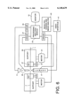
- FIG. 6 is a schematic view, partly illustrated as a block diagram, of a device for splicing optical fibers
- FIG. 7 is a flow chart of different operative steps performed in welding a fiber having a single core to a twin-core fiber
- FIG. 8 is a screen image captured before the welding step for determination of a desired offset
- FIG. 9 is a screen image captured during the welding step for determination of a desired offset
- FIG. 10 is a screen image captured during the final welding of fiber ends to each other
- FIG. 11 is a screen image captured after final welding to each other
- FIGS. 12 and 13 are schematic sectional views of fiber ends located next to each other.
- FIGS. 1a, 2a and 3a the light beam path is schematically shown when a parallel light beam (coming from above as seen in the figures) passes through an optical fiber 1, 1' of standard type having a core 3, and of a type having two cores 3' respectively, where the latter type is rotated to two different orientations around its longitudinal axis 7.
- the optical fibers 1, 1' have a cladding or cladding 5 having an essentially circular cylindrical outer surface, which encloses the cores 3, 3'.
- the single core 3 of a standard fiber 1 is located approximately symmetrically inside the cladding 5, i.e. approximately concentrically thereto and consequently in such a manner that the longitudinal axes 7 of the core 3 and the cladding approximately coincide.
- the cores 3' of the twin-core fiber 1' can normally be assumed to have approximately the same diameter as the core 3 of the standard fibers and they are located at places in relation to the longitudinal axis 7 of the fiber 3', which are located more or less exactly diametrically opposite to each other as seen in the cross section of the fiber, i.e. so that they are located approximately in a plane 8 passing through the longitudinal axis 7 of the fiber 1' and symmetrically in relation to the longitudinal axis 7 of the fiber.
- the end surfaces of the cores of the two fiber ends, which are to be spliced, are to be placed opposite to each other, in order to obtain a maximal transmission of light from one of the fiber cores in one end of the twin-core fiber to the fiber core in the end of the standard fiber.
- FIGS. 1b, 2b and 3b intensity curves of light, which has passed through the fibers 1, 1', are shown, the intensity curves being taken along a direction perpendicular to the incident parallel light beam, and perpendicular to the longitudinal axis 7 of the optical fiber. Further, the curve is captured along a line, which extends approximately through the focal line for the cylindrical lens, which is formed by the cladding 5 of the fiber.
- a rather high central peak 9 corresponding to the longitudinal axis 7 of the fiber, and next to this peak regions 10 having a relatively constant, low light intensity, are obtained as shown in FIG. 1b.
- regions 10 having a low light intensity there are regions having a constant higher intensity, which is the kind of light, which has travelled past the fiber and is basically unaffected thereof.
- the transition to these regions then corresponds to the outer sides or surfaces of the fiber, as seen in the incident direction of the light, and the very border or transition to these outer regions can be used for positioning the fiber in a transverse or lateral direction, see below.
- FIG. 2a an orientation of an optical twin-core fiber 1' is shown, in which the fiber cores 3' are located, so that they are both located aligned with and symmetrically in relation to the direction of incident beam.
- Light rays, which are incident to the cores 3' do not materially contribute to the light intensity, which can be observed on the other side of the fiber, i.e. after the light rays passing through the fiber 1'. Deflections of the light rays occur namely during their travel into and out of these regions and at reflections to the surface of the fiber cores.
- FIG. 3a the orientation of the optical fiber 1' is instead such, that the two cores 3' are essentially located along a diameter 8 of the optical fiber 1' being perpendicular to the direction of the incident parallel beam.
- some of the outer incident light rays are indeed prevented from passing through the optical fiber due to the interfering effect of the cores 3', but central light rays coming from directions, which are located next to and close to the fiber axis 7, pass therethrough.
- a corresponding light intensity curve, which to a considerable amount is formed by the central rays and which is shown in FIG. 3b, has a central peak 9, which has a considerably larger height in this case compared to the curve of FIG. 2b.
- FIGS. 1b, 2b and 3b show two extreme cases of the curve, so that at other rotational positions of the twin-core fiber height values h are obtained, which are in the range between the height values h for the curves illustrated in these figures.
- this value h which thus constitutes the difference between the height of the central peak 9 and the directly surrounding portions 10 of the light intensity curve, determined as has been described above, is determined for rotations of the fiber 1, 1' at different angular positions.
- This value h is determined for different angular positions of the optical fiber 1, 1', for instance for each tenth degree. Curves of such determined height values h appear from the photograph of FIG. 4 of a screen image, which has been calculated by an automatic splicing device, which will be described hereinafter, and which is shown by the monitor thereof. In the top portion of FIG. 4, the values h for a twin-core fiber at different rotational positions are hence shown by the bright points and in the bottom portion of FIG. 4 the corresponding height values for a fiber having a single core are seen.
- the values in the bottom portion are rather constant for different rotations, since the fiber in this case is essentially rotationally symmetric, of course having some small deviations from a circular shape and concentric positions, which give the small variations in the values for different rotation angles.
- the values for a twin-core fiber have large variations for different angular positions, having extreme values corresponding to fiber positions according to FIGS. 2a and 3b.
- the values h for the twin-core fiber present also large differences for fibers of different manufacture and design, for instance depending on the distance between the two cores 3', the diameters thereof, refractive index gradients, etc.
- FIG. 5 Essential optical components in a commercially available splicing device for optical fibers of standard type are shown in FIG. 5 with a standard fiber 1 having a single core and a twin-core fiber 1' mounted in the device.
- Two light sources 11 are arranged in such a way that they emit light beams, which reach the end regions of the optical fibers 1, 1' under mutually perpendicular directions, the x- and y-direction, respectively.
- the light beams passing through the fibers are deflected by means of mirrors 13 and are focused to one single parallel beam by means of a beam splitter 15.
- the single parallel beam obtained in this manner hits the light sensitive elements of a video camera 17 of CCD-type, which is connected to a monitor 19.
- Lens systems not shown, can be arranged at different locations of the light beam path in order to obtain sharp reproductions.
- FIG. 6 The mechanical and electronic components in such a device for splicing two optical fibers are schematically shown in FIG. 6.
- This device is fundamentally a conventional automatic splicing device for optical fibers supplemented with devices for orientating the fibers angularly and having special routines for analysing the determined light intensity curves.
- the two optical fibers 1 and 1' which are to be spliced, are placed with their ends in special retainers 27, by means of which the fibers can be rotated about their longitudinal axes.
- These retainers 27 are further arranged on conventional alignment supports 29 for the fiber ends of the splicing machine.
- the fiber supports 29 can be operated in relation to each other, in the same perpendicular directions x and y, which are indicated by the two light beam directions from the lamps 11 in FIG. 4, and also in the longitudinal direction of the fibers by means of drive motors 31, which are controlled by logical circuits and software in a processor logic module 33.
- the lamps 11 are activated by their own driver circuits 35 of the processor logic 33.
- Welding electrodes 25, at the points of which the fiber ends are to be placed, are energized by their driver circuits 37 controlled by the processor logic 33.
- the video camera 17 captures the image of the fiber ends and provides the corresponding video signals through a video interface 41 to an image processing and image analysis module 43.
- the result of the image processing and the image analysis in this module 43 is sent to the processor logic module 33 and the result can be shown on the monitor 19. Also the directly obtained image of the end region of the fibers captured by means of the video camera 39 can be shown on the monitor 19.
- FIG. 7 a method is illustrated by means of a block diagram, for splicing a twin-core fiber to an optical fiber of standard type having a single core in which the splicing is performed with an alignment of a core in the twin-core fiber with the core in the standard type fiber, so that the obtained splice in the normal case gets an acceptably low attenuation.
- the procedure is started in a step 701 by inserting the fiber ends of the optical fibers 1 and 1' respectively into the fiber retainers 27 in the automatic splicing device as described above.
- the apparatus is then started by operating some suitable operating key or similar device, not shown, so that the execution start of a program which is present in the processor logic part 33.
- a rough alignment in the transverse directions in relation to the fibers is performed in the conventional manner, i.e. an alignment of the fibers in the x- and y-directions, and further the end surfaces of the fiber ends are brought to a position close to each other, centrally between the points of the electrodes 25.
- An image is captured in this step and is automatically analyzed by the image processing and image analysis part 43 in order to make certain that the fiber ends are well cleansed and that there are no remaining particles on the outer surfaces of the fiber ends. If particles of dirt should be present, a suitable message can be shown on the monitor and the procedure be stopped until the fiber ends have been cleansed and again been placed in the retainers.
- the image obtained in this position is analyzed in a step 707 for making certain that the end surfaces are located in a right angle or at least in angles very close to a right angle in relation to the longitudinal direction of the fiber ends.
- the longitudinal directions of the fiber ends i.e. the outer surfaces of the fiber ends, as appearing on the monitor 19 are located well horizontally in the image, i.e. that they have the position appearing in particular from the screen image on the monitor 19 of FIG. 5. If these different checks should give a negative result, some suitable message is shown on the monitor, whereupon an operator can take proper actions, such as releasing a fiber end and again perform a cutting of the end in order to obtain a cut surface, which is located in a more perpendicular direction.
- this positioning is performed with a feedback control through a continuous image analysis and feedback of the result of the image analysis to the processor logic 33, which controls the driver circuits 31 for obtaining the accurate alignment.
- the end surfaces of the fiber ends then become placed exactly centrally between the ends of the electrodes 25.
- a refocusing is performed, so that a maximal lens effect is obtained, i.e. as large light intensity as possible in the central longitudinal region. It is made by moving a main lens, not shown, belonging to the video camera 17.
- a step 713 in which at least the end of the twin-core fiber is turned in suitable, equally large steps, for instance of the size 10°, around its longitudinal axes, is performed in order to capture curves of the type illustrated in FIG. 4.
- a step 715 the fiber 1' having twin cores is rotated to the position shown in FIGS. 2a and 5, in which the maximal value of the height h is obtained in a light intensity curve as seen in the x-direction and which has been determined by an evaluation of the captured curves for different rotational angles.
- an alignment is to be performed only with regard to the outer surfaces of the fiber ends, i.e. the outer surfaces of the cladding 5, and therefor the focusing of the obtained image on the video camera 17 is again adjusted in a step 717 by controlling the lens system for the video camera, so that these outer surfaces are sharply reproduced on the light sensitive surface of the video camera 17.
- the fiber 1' having twin cores is of an unknown or new type, the distance between its two cores 3' must in some way be measured or determined. Thus, in this case there are no such data stored in the processor logic module 33 in the splicing machine.
- the decision that this case is at hand is made in a block 719, and hence if no such data are stored for the fiber 1' having twin cores, a fine alignment of the outer sides of the claddings of the fiber ends is performed in a step 721, like in the block 709, and also an accurate alignment in the longitudinal direction, so that the end surfaces of the fiber ends are placed in the position for being welding to each other, centrally between the points of the electrodes 35.
- a screen image captured of this step is shown in FIG. 8.
- a block 727 the value of the lateral offset determined in that way between in this case the upper core in the twin-core fiber 1' and the single core in the standard fiber 1 is stored in a memory in the processor logic part 33 to be used, when a correct splice is to be performed between the same fibers or fiber types.
- An image captured of the fiber ends in a heated state during the welding process is also stored in a memory and this image together with the calculated numerical value of the offset between the fiber cores are shown on the monitor 19. After this the procedure is terminated in a block 729 and the device, together with lamps, driver circuits, etc. is turned off.
- a standard value of the lateral offset has now been determined between a core in the twin-core fiber 1' and the core in the standard fiber 1, when the claddings are aligned with each other, which value is essentially equivalent to half of the distance between the two cores in the twin-core fiber, since it can be assumed that at the set rotational angle of the twin-core fiber, this fiber is located always in the same position having one core at the top and the other core located vertically below.
- the same fiber is now to be spliced in a correct manner with an alignment between the upper fiber core of the twin-core fiber and the core in the standard fiber, the earlier performed splice region and the region of the fiber ends adjacent thereto are to be removed, by cutting the fibers at suitable locations and preparing their ends in the usual manner for splicing.
- a block 731 is performed after the block 719 in this case.
- a transverse fine alignment, in the x- and y-directions is performed, compare the block 721, so that the fiber ends are here placed with a predetermined calculated, suitable offset in relation to each other. This offset then somewhat exceeds the stored offset value.
- a positioning of the fiber ends in the longitudinal direction is performed, so that their end surfaces are placed close to each other centrally between the points of the electrodes 25.
- a block 733 welding of the fiber ends to each other is performed with an indirect check that the previously determined offset between the fiber cores, as stored in the block 727, is obtained through a continuous observation of the outer side of the fibers, so that the value of the offset of the outer sides will agree with the stored offset value.
- the calculation of a suitable initial value for the alignment, the continuous alignment itself, during the heating and welding to each other in the blocks 731 and 733 are advantageously performed in a manner, described in the Swedish patent application SE-A 9400781-2, "Controlled splicing of optical fibers", filed Mar. 8, 1994, which is incorporated by reference herein.
- an image is captured of the joint during the very welding process and the image is automatically analyzed by the image processing and image analysis part 43 in order to evaluate the loss in the obtained joint through an evaluation of a possible offset in the image between the upper fiber core and in the core of the standard fiber, as is described in the Swedish patent SE-C 469 200, cited above.
- An image captured of the fiber ends in a heated state is also stored and is shown on the monitor 19, see the picture of FIG. 10, from which the alignment of the fiber cores appears.
- the evaluated numerical value of the loss in the fiber splice is then shown on the monitor 19 and also an image of the fiber splice in a cooled state, as is seen in FIG.
Landscapes
- Physics & Mathematics (AREA)
- Engineering & Computer Science (AREA)
- Plasma & Fusion (AREA)
- General Physics & Mathematics (AREA)
- Optics & Photonics (AREA)
- Mechanical Coupling Of Light Guides (AREA)
- Investigating Or Analysing Materials By Optical Means (AREA)
- Treatment Of Fiber Materials (AREA)
Applications Claiming Priority (3)
| Application Number | Priority Date | Filing Date | Title |
|---|---|---|---|
| SE9403642A SE505771C2 (sv) | 1994-10-24 | 1994-10-24 | Förfarande och anordning för bestämning av avståndet mellan kärnor i en optisk fiber samt användning av förfarandet respektive anordningen |
| SE9403642 | 1994-10-24 | ||
| PCT/SE1995/001262 WO1996012980A1 (en) | 1994-10-24 | 1995-10-24 | Splicing an optical fiber having twin cores and a fiber having a single core |
Publications (1)
| Publication Number | Publication Date |
|---|---|
| US6148639A true US6148639A (en) | 2000-11-21 |
Family
ID=20395728
Family Applications (1)
| Application Number | Title | Priority Date | Filing Date |
|---|---|---|---|
| US08/817,571 Expired - Lifetime US6148639A (en) | 1994-10-24 | 1995-10-24 | Splicing an optical fiber having twin cores |
Country Status (7)
| Country | Link |
|---|---|
| US (1) | US6148639A (sv) |
| EP (1) | EP0788611B1 (sv) |
| JP (1) | JP3654904B2 (sv) |
| AU (1) | AU3821795A (sv) |
| DE (1) | DE69535949D1 (sv) |
| SE (1) | SE505771C2 (sv) |
| WO (1) | WO1996012980A1 (sv) |
Cited By (6)
| Publication number | Priority date | Publication date | Assignee | Title |
|---|---|---|---|---|
| US6470119B1 (en) * | 1996-09-27 | 2002-10-22 | Siemens Aktiengesellschaft | Device for coupling light between two waveguide end surfaces |
| WO2006119949A1 (de) * | 2005-05-06 | 2006-11-16 | Ccs Technology, Inc. | Vorrichtung und verfahren zur ermittlung einer dämpfung an einer verbindungsstelle zweier optischer fasern |
| US20100043953A1 (en) * | 2004-05-24 | 2010-02-25 | Kevin Riddett | Process and apparatus for manufacturing an optical cable |
| US20110064366A1 (en) * | 2008-09-16 | 2011-03-17 | Afl Telecommunications Llc | Automatic alignment for splicing of non-circular fiber |
| US9164234B2 (en) | 2012-12-14 | 2015-10-20 | Ofs Fitel, Llc | Splicing twisted multiple core optical fibers |
| CN108507977A (zh) * | 2018-05-25 | 2018-09-07 | 哈尔滨工程大学 | 一种基于光栅辅助型模式耦合的孔助双芯光纤传感器 |
Families Citing this family (4)
| Publication number | Priority date | Publication date | Assignee | Title |
|---|---|---|---|---|
| SE506956C2 (sv) * | 1995-10-24 | 1998-03-09 | Ericsson Telefon Ab L M | Förfarande och anordning för att bestämma vinkelläget för en optisk axiell asymmetri, samt användning av förfarandet respektive anordningen |
| JP3065271B2 (ja) | 1997-04-10 | 2000-07-17 | 住友電気工業株式会社 | 融着接続装置 |
| SE523329C2 (sv) * | 2000-06-20 | 2004-04-13 | Ericsson Telefon Ab L M | Bestämning av optisk fibertyp |
| CN102261978B (zh) * | 2011-04-28 | 2013-01-30 | 浙江师范大学 | 基于双芯双孔光纤实现液压传感的方法及装置 |
Citations (5)
| Publication number | Priority date | Publication date | Assignee | Title |
|---|---|---|---|---|
| DE3829118A1 (de) * | 1988-08-27 | 1990-03-01 | Standard Elektrik Lorenz Ag | Faseroptisches bandfilter |
| SE469200B (sv) * | 1990-08-24 | 1993-05-24 | Ericsson Telefon Ab L M | Foerfarande och anordning foer att skarva optiska fibrer respektive bestaemma foerlusten/daempningen i en skarv mellan tvaa optiska fibrer |
| WO1995014945A1 (en) * | 1993-11-29 | 1995-06-01 | Telefonaktiebolaget Lm Ericsson | Determination of angular offset between optical fibers having optical, axial asymmetry and alignment and splicing of such fibers |
| US5638476A (en) * | 1994-03-08 | 1997-06-10 | Telefonaktiebolaget Lm Ericsson | Controlled splicing of optical fibers |
| US5758000A (en) * | 1995-10-24 | 1998-05-26 | Telefonaktiebolaget Lm Ericsson | Determination of angular position optical fibers having axial asymmetries and aligning and splicing such fibers |
Family Cites Families (5)
| Publication number | Priority date | Publication date | Assignee | Title |
|---|---|---|---|---|
| JPH0697284B2 (ja) * | 1985-06-24 | 1994-11-30 | 株式会社フジクラ | デユアルコアフアイバの励振器 |
| US4948412A (en) * | 1985-09-16 | 1990-08-14 | Fujikura Ltd. | Method of fusion splicing single-mode optical fibers using an arc discharge |
| GB2201529A (en) * | 1987-02-26 | 1988-09-01 | Bicc Plc | Aligning optical fibres for splicing using video signals |
| US5013345A (en) * | 1987-12-04 | 1991-05-07 | Fujikura Ltd. | Method of fusion-splicing polarization maintaining optical fibers |
| EP0400408B1 (de) * | 1989-06-02 | 1996-11-27 | Siemens Aktiengesellschaft | Verfahren zur Ausrichtung zweier Lichtwellenleiter-Faserenden und Einrichtung zur Durchführung des Verfahrens |
-
1994
- 1994-10-24 SE SE9403642A patent/SE505771C2/sv not_active IP Right Cessation
-
1995
- 1995-10-24 JP JP51384796A patent/JP3654904B2/ja not_active Expired - Lifetime
- 1995-10-24 AU AU38217/95A patent/AU3821795A/en not_active Abandoned
- 1995-10-24 DE DE69535949T patent/DE69535949D1/de not_active Expired - Lifetime
- 1995-10-24 EP EP95936181A patent/EP0788611B1/en not_active Expired - Lifetime
- 1995-10-24 WO PCT/SE1995/001262 patent/WO1996012980A1/en active Application Filing
- 1995-10-24 US US08/817,571 patent/US6148639A/en not_active Expired - Lifetime
Patent Citations (5)
| Publication number | Priority date | Publication date | Assignee | Title |
|---|---|---|---|---|
| DE3829118A1 (de) * | 1988-08-27 | 1990-03-01 | Standard Elektrik Lorenz Ag | Faseroptisches bandfilter |
| SE469200B (sv) * | 1990-08-24 | 1993-05-24 | Ericsson Telefon Ab L M | Foerfarande och anordning foer att skarva optiska fibrer respektive bestaemma foerlusten/daempningen i en skarv mellan tvaa optiska fibrer |
| WO1995014945A1 (en) * | 1993-11-29 | 1995-06-01 | Telefonaktiebolaget Lm Ericsson | Determination of angular offset between optical fibers having optical, axial asymmetry and alignment and splicing of such fibers |
| US5638476A (en) * | 1994-03-08 | 1997-06-10 | Telefonaktiebolaget Lm Ericsson | Controlled splicing of optical fibers |
| US5758000A (en) * | 1995-10-24 | 1998-05-26 | Telefonaktiebolaget Lm Ericsson | Determination of angular position optical fibers having axial asymmetries and aligning and splicing such fibers |
Non-Patent Citations (2)
| Title |
|---|
| English Abstract of WPI Accession No. 93 043031. * |
| English Abstract of WPI Accession No. 93-043031. |
Cited By (7)
| Publication number | Priority date | Publication date | Assignee | Title |
|---|---|---|---|---|
| US6470119B1 (en) * | 1996-09-27 | 2002-10-22 | Siemens Aktiengesellschaft | Device for coupling light between two waveguide end surfaces |
| US20100043953A1 (en) * | 2004-05-24 | 2010-02-25 | Kevin Riddett | Process and apparatus for manufacturing an optical cable |
| WO2006119949A1 (de) * | 2005-05-06 | 2006-11-16 | Ccs Technology, Inc. | Vorrichtung und verfahren zur ermittlung einer dämpfung an einer verbindungsstelle zweier optischer fasern |
| US20110064366A1 (en) * | 2008-09-16 | 2011-03-17 | Afl Telecommunications Llc | Automatic alignment for splicing of non-circular fiber |
| US8282291B2 (en) * | 2008-09-16 | 2012-10-09 | Afl Telecommunications Llc | Automatic alignment for splicing of non-circular fiber |
| US9164234B2 (en) | 2012-12-14 | 2015-10-20 | Ofs Fitel, Llc | Splicing twisted multiple core optical fibers |
| CN108507977A (zh) * | 2018-05-25 | 2018-09-07 | 哈尔滨工程大学 | 一种基于光栅辅助型模式耦合的孔助双芯光纤传感器 |
Also Published As
| Publication number | Publication date |
|---|---|
| SE9403642D0 (sv) | 1994-10-24 |
| JP3654904B2 (ja) | 2005-06-02 |
| EP0788611B1 (en) | 2009-05-06 |
| EP0788611A1 (en) | 1997-08-13 |
| WO1996012980A1 (en) | 1996-05-02 |
| AU3821795A (en) | 1996-05-15 |
| DE69535949D1 (de) | 2009-06-18 |
| SE505771C2 (sv) | 1997-10-06 |
| SE9403642L (sv) | 1996-04-25 |
| JPH10507849A (ja) | 1998-07-28 |
Similar Documents
| Publication | Publication Date | Title |
|---|---|---|
| JP3737107B2 (ja) | 光学的な軸非対称性を持つ光ファイバの間の角オフセットの決定とファイバの芯合わせおよび継ぎ合わせ | |
| JP3500850B2 (ja) | リボン型光ファイバの突き合せ部を観察する方法及び観察装置 | |
| US5638476A (en) | Controlled splicing of optical fibers | |
| US6148639A (en) | Splicing an optical fiber having twin cores | |
| CN100412585C (zh) | Pm光纤对准 | |
| JP3256286B2 (ja) | 光コネクタのコア偏心測定方法及び光コネクタ製造方法 | |
| JP3078133B2 (ja) | 光導波路の整列状態検査方法および光導波路 | |
| JPH02196204A (ja) | 定偏波光フアイバの軸合せ方法 | |
| JPS6046509A (ja) | 光フアイバのコア検出・軸合せ方法及びその装置 | |
| JPH09126732A (ja) | 光ファイバ間の距離定量方法およびシステム | |
| JPH0360086B2 (sv) | ||
| JP3418296B2 (ja) | 異径光ファイバの軸ずれ量検出方法 | |
| JPH0648323B2 (ja) | 光フアイバ軸ずれ測定方法 | |
| JP3213140B2 (ja) | 光コネクタのコア偏心測定方法、および、これにより測定された光コネクタ | |
| JPH06130251A (ja) | 光コネクタのコア偏心測定方法および光コネクタ | |
| JP2859680B2 (ja) | 偏波保持光ファイバカプラの製造方法 | |
| JPH0374364B2 (sv) | ||
| JPH1026510A (ja) | 光ファイバの位置検出方法 | |
| JP2024004068A (ja) | 融着接続装置および融着接続方法 | |
| JPH07157144A (ja) | 光部品の寸法測定方法 | |
| JPS6022322Y2 (ja) | 細径コア光フアイバの目視軸合装置 | |
| JPH0625809B2 (ja) | 光フアイバコアの観察装置 | |
| JP2938317B2 (ja) | 光ファイバの位置をv溝に合わせる方法 | |
| JPH08313775A (ja) | 光軸整合検知装置 | |
| JPS62198804A (ja) | 光フアイバの軸ずれ測定方法 |
Legal Events
| Date | Code | Title | Description |
|---|---|---|---|
| AS | Assignment |
Owner name: TELEFONAKTIEBOLAGET LM ERICSSON, SWEDEN Free format text: ASSIGNMENT OF ASSIGNORS INTEREST;ASSIGNORS:ZHENG, WENXIN;HULTEN, OLA;REEL/FRAME:008706/0243;SIGNING DATES FROM 19970701 TO 19970704 |
|
| STCF | Information on status: patent grant |
Free format text: PATENTED CASE |
|
| FEPP | Fee payment procedure |
Free format text: PAYOR NUMBER ASSIGNED (ORIGINAL EVENT CODE: ASPN); ENTITY STATUS OF PATENT OWNER: LARGE ENTITY |
|
| FPAY | Fee payment |
Year of fee payment: 4 |
|
| FPAY | Fee payment |
Year of fee payment: 8 |
|
| FPAY | Fee payment |
Year of fee payment: 12 |