US6078481A - Tape storage cartridge having two-level tape path - Google Patents
Tape storage cartridge having two-level tape path Download PDFInfo
- Publication number
- US6078481A US6078481A US09/093,224 US9322498A US6078481A US 6078481 A US6078481 A US 6078481A US 9322498 A US9322498 A US 9322498A US 6078481 A US6078481 A US 6078481A
- Authority
- US
- United States
- Prior art keywords
- tape
- cartridge
- layer
- guide
- rotatable hub
- Prior art date
- Legal status (The legal status is an assumption and is not a legal conclusion. Google has not performed a legal analysis and makes no representation as to the accuracy of the status listed.)
- Expired - Fee Related
Links
- 230000005291 magnetic effect Effects 0.000 claims abstract description 26
- 239000000758 substrate Substances 0.000 claims abstract description 17
- 239000000696 magnetic material Substances 0.000 claims abstract description 5
- SZVJSHCCFOBDDC-UHFFFAOYSA-N iron(II,III) oxide Inorganic materials O=[Fe]O[Fe]O[Fe]=O SZVJSHCCFOBDDC-UHFFFAOYSA-N 0.000 claims description 4
- 239000002245 particle Substances 0.000 claims description 4
- 239000010410 layer Substances 0.000 description 86
- 230000008901 benefit Effects 0.000 description 7
- 230000008859 change Effects 0.000 description 5
- 239000002356 single layer Substances 0.000 description 5
- 230000004907 flux Effects 0.000 description 4
- 230000007246 mechanism Effects 0.000 description 4
- 238000000034 method Methods 0.000 description 4
- 230000001133 acceleration Effects 0.000 description 3
- 230000000694 effects Effects 0.000 description 3
- 230000005540 biological transmission Effects 0.000 description 2
- 238000013016 damping Methods 0.000 description 2
- 239000000463 material Substances 0.000 description 2
- 238000000926 separation method Methods 0.000 description 2
- 230000002463 transducing effect Effects 0.000 description 2
- 230000032258 transport Effects 0.000 description 2
- 238000004804 winding Methods 0.000 description 2
- 230000009977 dual effect Effects 0.000 description 1
- 230000005294 ferromagnetic effect Effects 0.000 description 1
- 238000003780 insertion Methods 0.000 description 1
- 230000037431 insertion Effects 0.000 description 1
- 238000004519 manufacturing process Methods 0.000 description 1
- 239000000049 pigment Substances 0.000 description 1
- 229920006395 saturated elastomer Polymers 0.000 description 1
- 230000007704 transition Effects 0.000 description 1
Images


Classifications
-
- G—PHYSICS
- G11—INFORMATION STORAGE
- G11B—INFORMATION STORAGE BASED ON RELATIVE MOVEMENT BETWEEN RECORD CARRIER AND TRANSDUCER
- G11B23/00—Record carriers not specific to the method of recording or reproducing; Accessories, e.g. containers, specially adapted for co-operation with the recording or reproducing apparatus ; Intermediate mediums; Apparatus or processes specially adapted for their manufacture
- G11B23/02—Containers; Storing means both adapted to cooperate with the recording or reproducing means
- G11B23/04—Magazines; Cassettes for webs or filaments
- G11B23/08—Magazines; Cassettes for webs or filaments for housing webs or filaments having two distinct ends
- G11B23/087—Magazines; Cassettes for webs or filaments for housing webs or filaments having two distinct ends using two different reels or cores
Definitions
- the invention relates to a high performance tape cartridge. More particularly, the invention is directed toward a tape path within a tape cartridge that allows high head/tape interface pressure and low tape tension.
- Tape is a known medium or media for the storage of audio, video, and computer information. The information is typically written to and read from the tape magnetically and/or optically. Such tapes are available spooled on individual reels and in single or dual reel tape cassettes/cartridges. The tape in a single reel tape cartridge must be mechanically threaded through the tape path and spooled onto a take-up reel after insertion into a tape device/drive.
- the tape path for any type of tape cartridge and tape drive includes a tape head in close proximity to the tape. Tape cartridges include an opening through which a tape head from a tape drive is inserted. The tape head has one or more transducer elements for writing to and/or reading from the tape.
- the tape is driven past the tape head by a capstan, or by direct drive of the tape reels.
- the tape on the tape path passes the opening for the tape head one time.
- one layer or level of tape is presented at the tape head opening when the tape cartridge is inserted into the tape drive.
- Cassettes or cartridges including tape are commonly used to back up computer information from all types of computer systems. This is especially common in work environments where the information may be backed up daily.
- Home computers also may be equipped with tape drives which use tape cartridges to back up computer information.
- An additional usage for tape and tape cartridges is for the storage of vast amounts of data.
- one or more tape cartridges may be used in a library which includes a tape drive coupled with a picking mechanism and a storage area storing a number of tape cartridges accessible by the picking mechanism.
- the picking mechanism picks the tape cartridges and inserts them into the tape drives when the information on the drive is needed.
- the picking mechanism removes the tape cartridges from the tape drives and returns them to the storage area when the information is no longer needed.
- Magnetic tape drives typically use a reel-to-reel tape transport design, or "tape path", for controllably advancing the tape past an adjacent tape head.
- the tape is wound upon 2 reels, one reel at each end.
- the tape is advanced by rotation of such reels.
- Tension variation and velocity variation in reel-to-reel tape paths can cause many problems in tape drives and tape cartridges. Variations in tape velocity and tension cause vibration.
- Tape vibration can be characterized according to the propagation velocity of the vibratory mode, the length and geometry of the vibration transmission path, and the terminating conditions of the vibration transmission path. Such vibration in the tape can disrupt the head-tape interface, and thus effects the overall operation and performance of the drive.
- tape cartridges include an opening for the tape head.
- the tape on the tape path passes the opening one time so that one layer or level of tape is presented to the tape head when it is inserted in the opening of the cartridge and is in a transducing position.
- One way of increasing the data capacity of a tape cartridge is to place more tape into a tape cartridge.
- tapes continually are made from thinner material so that more feet of tape can be wound onto the hubs in a tape cartridge. Handling thinner and thinner tape or media is one of the major problems faced by designers of tape cartridges and tape drives.
- Tape tension generally must be reduced when a thinner tape is used to avoid certain problems such as over stressing and other damage.
- the tape flies higher with respect to the head at the head/tape interface. The farther the head is from the media the poorer the transitions on the media are. As a result, higher flying tape results in signals having reduced quality.
- Telescoping is a phenomenon that occurs when a tape having one longer edge is wound onto a hub.
- the longer edge is typically ruffled.
- the longer edge stays at a longer radius and the shorter edge goes to a shorter radius.
- the end result is that the tape tends spiral toward one of the edges of the hub while it is being wound.
- the tendency to telescope can result in deformation of the sidewall of a hub.
- felt pressure pads are provided near the opening in the tape head to control the pressure between the tape and the tape head.
- Felt pressure control pads have a number of problems. Among the problems include threading the tape in a cartridge having the felt pressure pads. Another problem is that the felt pressure pads generate debris over their life. Still another problem is that as they wear the pressure may change and they also collect debris. During manufacture, there is also control issues with respect to the size and placement of the felt pressure pads.
- What is needed is a tape cartridge that uses low tension to accommodate the use of thinner tape. There is also a need for a tape cartridge that does not require felt pressure pads to maintain an adequate tape pressure at the head/tape interface to keep the flying height of the tape low so that good signal quality is maintained. What is also needed is a tape path which dampens out accelerations of the tape in the vertical direction so that a head which track follows will be better able to follow the tracks on the tape.
- a tape cartridge includes a first rotatable hub and a second rotatable hub and a tape head receiving region.
- a flexible recording tape is wound upon the first rotatable hub and the second rotatable hub.
- the flexible recording tape is routed through the cartridge to provide two or more levels or layers of tape at the tape head receiving region.
- the tape cartridge may also have a single hub and may include a tape path through the cartridge to provide two or more levels or layers of tape at the tape head receiving region. Tape guides and pins may also be included in the tape cartridge.
- the tape path may include a flexible tape routed through the cartridge to provide two or more levels of tape at one or more of the tape guides or tape pins within the tape cartridge.
- the tape path through the tape cartridge may also include the tape head.
- forming a tape path having two or more layers formed at the tape head receiving region of the tape cartridge allows the tape head to contact the tape at a high pressure for a given lower tape tension for a given head and tape interface.
- the contact pressure across or over the head can be higher than when a single layer of tape is presented to the tape head.
- the pressure at the tape head can be kept at a level where the tape will fly at a height to produce good signals when writing to or reading from the tape, despite the fact that a lower tape tension is used. Using lower tension also requires less torque for the drive motor of the tape drive.
- lower tension lowers the load on the tape guides and tape pins which do not carry multiple layers of tape. Edge loading on the tape is also reduced in tape drives and tape cartridges with compliant or spring loaded tape guides since the load is being shared by two or more or more layers of tape. This helps reduce tape edge damage, distortion, rippling and debris generation. Lower tension also reduces tape telescoping and also reduces tape creep by lowering stressing in the stored tape.
- the length of the tape path is longer.
- the closed loop track following servo performance is enhanced.
- Improved servo performance improves tape tracking.
- Improved tape tracking enables higher track densities on the tape.
- thinner tape can now be used. The increased track densities and thinner tape will allow for larger data capacities for a tape cartridge of a particular form factor.
- a tape for use in a tape drive including a double loop type tape path includes a substrate having a magnetic layer applied to one side of the substrate, and having a backside of soft magnetic material applied to the other side of the substrate.
- the backside may includes particles of magnetite. The backside acts as a magnetic shield to prevent writing though the layer of tape nearest the head to the layer of tape underneath the layer of tape being written to.
- FIG. 1 shows a isometric view of a tape cartridge.
- FIG. 2 shows an isometric view of a tape cartridge with the pivoting access door open.
- FIG. 3 shows an exploded isometric view of a tape cartridge.
- FIG. 4 shows a schematic view of a tape drive and a cartridge.
- FIG. 5 shows a top view of the base of a tape cartridge and a first magnetic tape path within the tape cartridge.
- FIG. 6 shows a top view of the base of a tape cartridge and a second magnetic tape path within the tape cartridge.
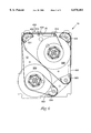
- FIG. 7 shows a top view of the base of a tape cartridge and a third magnetic tape path within the tape cartridge.
- FIG. 8 shows a schematic view of a the magnetic tape and head interface.
- FIG. 9 shows a top view of the base of a tape cartridge and a fourth magnetic tape path within the tape cartridge.
- FIG. 1 shows a isometric view of a tape cartridge 10.
- the tape cartridge 10 is shown as an example of one type of tape cartridge 10 in which the invention could be used. It should be noted that a tape cartridge 10 having any form factor or of any type could use the invention.
- U.S. Pat. No. 5,547,142 shows one example of a tape cartridge in which the invention could be used.
- U.S. Pat. No. 5,297,755 shows another example of a tape cartridge in which the invention could be used.
- the tape cartridge 10 includes a box-like housing formed by a mount plate or base 12 and a cover or shell 14. Shell 14 is secured to base 12 by screws inserted through a set of holes 15-19. Shell 14 also includes two holes 20 and 21 exposing portions of two tape hubs. As shown in FIG. 1, the tape hubs are toothed hub tape reels.
- a pivoting access door 26 is hinged between base 12 and shell 14 and is shown in the closed position.
- FIG. 2 shows an isometric view of a tape cartridge 10 with the pivoting access door 26 in an open position.
- tape cartridge 10 is shown with access door 26 pivoted to the open position, thereby exposing the inside of tape cartridge 10 through an opening referred to as the tape head receiving region and represented by arrow 25.
- the tape is not shown in FIG. 2 to permit viewing of the tape head receiving region 25.
- one or more tape heads may be brought into contact with the tape to permit read and/or write access to data on the tape, as will be described further herein.
- FIG. 3 shows an exploded isometric view of a tape cartridge 10.
- the tape cartridge 10 is shown exploded to expose the inner portion of the cartridge. For clarity, no tape is shown. Tape paths will be discussed below.
- a pin 62 secures base 12 at a hole 63 to shell 14 at a hole 64. Pin 62 is inserted through hole 68 to permit pivoting of access door 26.
- Base 12 includes various inner surfaces.
- Base 12 includes a floor or inner surface 50 and a set of inner mount surfaces 51 and 53 which are attached to the floor 50 and are in the same mount plane 52. Because mount surfaces 51 and 53 are in the same mount plane 52, various tape cartridge components can be precisely positioned relative to each other.
- the inner surface 50 is recessed with respect to the mount plane 52 to permit the unobstructed rotation of the two tape hubs 200 and 300.
- the two tape hubs 200 and 300 are mounted on the mount surfaces 51 and 53.
- Two axles 72 and 73 are secured to mount surfaces 52 and 53, respectively.
- the hubs of two toothed hub tape reels 200 and 300 are rotatably mounted upon hub axles 72 and 73, respectively.
- Axles 72 and 73 extend through openings in the two hub 200 and 300, respectively.
- the hubs 200 and 300 rotate on the two axles 72 and 73.
- Several components of tape cartridge 10 or a tape cartridge mount are mounted to or interface with inner surface 50.
- a first tape guide pin 100 and a second tape guide pin 101 are secured to mount surface 50.
- FIG. 4 shows a schematic view of a tape drive 400 and a tape cartridge 10.
- the tape drive 400 includes a housing 410 having a recess 420 for receiving the tape cartridge 10.
- the tape drive 400 also includes a tape head 430 positioned within the recess 420 so that when the tape cartridge 10 is inserted within the recess 420, the tape head 430 is inserted into the head receiving region 25. If the tape cartridge had a door 26 to the head receiving region 25, the door would have to be opened before the tape head 430 could be positioned within the tape head receiving region 25.
- the tape head 430 includes a number of transducing elements or read write heads (not shown) which are used to write information representing data to a tape 450.
- the tape 450 is passed over various guides and pins which are shown in FIGS. 5-7 below and past the tape head receiving portion 25 of the tape cartridge.
- the path which the tape takes over various guides and pins which are shown in FIGS. 5-7 below and past the tape head receiving portion 25 of the tape cartridge 10 is termed the tape path 452.
- the tape path 452 includes two layers or levels of tape which are passed over the tape head 430.
- the tape path 452 includes a double loop of tape 453 and presents two layers or levels of tape 450 over the tape head 430.
- the layer of tape 450 which actually flies over the tape head 430 is referred to as the outer layer 454 of tape 450.
- the layer of tape that is closest to the hub 200 is referred to as the inner layer 456 of tape 450.
- the tape is wound onto the hub 200 which is positioned closest to the head receiving portion 25 of the tape cartridge 10 and onto the hub 300.
- the tape 450 may be moved in either of two directions past the tape receiving portion 25 of the tape cartridge 10. It should be noted that the tape or media is very thin.
- FIG. 5 shows a top view of a base 12 with the shell 14 removed.
- FIG. 5 shows another tape path 452.
- the hubs 200 and 300 are shown rotatably attached to the base 12.
- the tape guides 501, 502, 503 and 504 guide the tape 450 along the tape path 452.
- the tape guides 501, 502, 503 and 504 provide surfaces along which the tape 450 can wrap around to change direction. The amount of direction change is typically defined by an angle ⁇ .
- Also attached to the base 12 is a first tape pin 510 and a second tape pin 512.
- the tape pins 510 and 512 typically have smaller radius when compared to the tape guides 501, 502, 503, and 504.
- the tape pins 510 and 512 also generally change the direction of the tape slightly or over a smaller angle ⁇ when compared to the angle ⁇ associated with the tape guides 501, 502, 503, and 504.
- the tape pins 510 and 512 are positioned near the tape head receiving portion 25 of the tape cartridge 10.
- the tape pins 510 and 512 keep the tape flying over the tape head 430 (shown in FIG. 4) in close proximity to the tape head 430.
- the tape path 452 begins at the hub 200 and passes over the tape guide 503, the tape guide 502, the tape pin 512, the tape pin 510, and the tape guide 501 and then between the hub 200 and the hub 300.
- the portion of the tape 450 passing initially over the tape guide 503, the tape guide 502 and the tape guide 501 is the inner layer 456 of tape 450.
- the tape then passes over the tape guide 503, the tape guide 502 and the tape guide 501 a second time and past the hub 300 to the tape guide 504.
- the tape is then wound onto the hub 300.
- the portion of the tape 450 that passes over the tape guide 503, the tape guide 502 and the tape guide 501 the second time is the outside layer 454 of tape 450.
- the double looped portion 453 includes the inside layer 456 and the outside layer 454 that passes over the tape guide 503, the tape guide 502 and the tape guide 501.
- the tape pin 512 and the tape pin 510 are positioned near the tape head receiving opening 25. As mentioned before, the tape pin 512 and the tape pin 510 direct the tape over the tape head 430.
- FIG. 6 shows a top view of the base 12 of a tape cartridge 10 and a second magnetic tape path 452 within the tape cartridge 10.
- the tape path 452 begins at the hub 200 and passes the tape pin 512, the tape pin 510, and the tape guide 501 and then between the hub 200 and the hub 300.
- the portion of the tape 450 passing initially over the tape guide the tape pin 512, the tape pin 510, and the tape guide 501 is the inner layer 456 of tape 450.
- the tape then passes over the tape guide 503, the tape guide 502 and the tape guide 501 a second time and past the hub 300 to the tape guide 504.
- the tape is then wound onto the hub 300.
- the portion of the tape 450 that passes over the tape guide the tape pin 512, the tape pin 510, and the tape guide 501 the second time is the outside or outer layer 454 of tape 450.
- the double looped portion 453 includes the inside layer 456 and the outside layer 454 that passes the tape guide the tape pin 512, the tape pin 510, and the tape guide 501.
- the tape pin 512 and the tape pin 510 are positioned near the tape head receiving opening 25. As mentioned before, the tape pin 512 and the tape pin 510 direct the tape over the tape head 430.
- One advantage is that having two levels or layers of tape 450 for the tape head 430 to contact allows a lower tape tension to be used for a given head and tape interface. In other words, if two layers of tape are presented at the tape head 430, the contact pressure across the head can be higher than when a single layer of tape is presented to the tape head 430. When thinner tape 450 is used, the tension can be lowered so side step many of the ill effects of over stressing the tape and the pressure at the tape head 430 can be kept at a level where the tape 450 will fly at a height to produce good signals when writing to or reading from the tape 450.
- lower tension also requires less torque for the drive motor of the tape drive 400.
- lower tension lowers the load on the tape guides 501, 502, 503 and 504 which do not carry multiple layers of tape.
- the force on tape guide 504 is reduced.
- the force on each of the tape guides 501 and 502, as well as on tape pins 510 and 512 is also reduced.
- the force on each of the tape guides 502, 503 and 504 is reduced.
- Edge loading on the tape is also reduced in tape drives and tape cartridges suing compliant or spring loaded guides since the load is being shared by two or more layers of tape. This helps reduce tape edge damage, distortion, rippling and debris generation.
- Lower tension also reduces tape telescoping and also reduces tape creep by lowering stressing in the stored tape.
- the length of the tape path is increased.
- the dampening between the layers slows the movement between the two layers of tape. Eliminating such rapid movement in the direction perpendicular to the length of the tape improves tape tracking. Improved tape tracking enables higher track densities on the tape.
- thinner tape can now be used. The increased track densities and thinner tape will allow for larger data capacities for a tape cartridge of a particular form factor.
- FIG. 7 shows a top view of the base 12 of a tape cartridge 10 and a third magnetic tape path 452 within the tape cartridge 10.
- the tape path 452 begins at the hub 200 and passes over the tape guide 503, around the hub 200 a second time and then around the tape guide 503 a second time.
- the tape passes to the tape guide 502, the tape pin 512, the tape pin 510, and the tape guide 501.
- the tape path continues to the hub 300 where it forms an outside layer.
- the tape path 452 passes over the tape guide 504 and then to then to the hub 300 and over the tape guide 504 and to the hub 300 where it is wound onto the hub 300.
- the portion of the tape 450 beginning at the hub 200 and passing over the tape guide 503 and then back to the hub 200 is the inner layer 756 of tape 450 forming the double loop 753.
- the portion of the tape 450 that passes from the hub 200 and over the tape guide 503 the second time is the outside layer 754 of tape 450 forming the double loop 753.
- the double looped portion 753 includes the inside layer 766 and the outside layer 764 that passes over the tape guide 503.
- the portion of the tape 450 ending at the hub 300 and passing over the tape guide 504 and then back to the hub 300 is the inner layer 766 of tape 450 forming the double loop 755.
- the portion of the tape 450 that passes from the hub 300 and over the tape guide 504 the second time is the outside layer 764 of tape 450 forming the double loop 755.
- the double looped portion 755 includes the inside layer 758 and the outside layer 759 that passes over the tape guide 504.
- tape paths 452 discussed above have all been within a tape cartridge 10. Some tape paths include a single hub. The end of the tape is retrieved and threaded through a tape drive 400. In these instances, the tape path is within the drive 400. It should be noted that a tape drive 400 could also include a multiple layers of tape at various points in the tape path.
- FIG. 9 shows a schematic of tape cartridge 10 which has a single hub 200 and a tape path 452 with multiple layers presented at the tape head receiving portion 25.
- the tape is wound onto hub 200. From the hub 200 it passes over a first guide 501 and wraps around a second tape guide 502 and back to the hub 200. From the hub 200, the tape 450 goes back to the tape guide 501 and to tape guide 502, and then to the drive take-up reel (not shown).
- the tape forms a double layer 453 in the area of the tape receiving portion 25.
- Older tape drives may have been designed to produce magnetic field at the write head which is strong enough to cause a write through problem on a thinner tape using one of the tape paths 452 discussed above.
- the solution may be necessary to allow downward compatability of tape cartridges with multiple layer portions of tape for use in drives designed for single layer tape cartridges.
- FIG. 8 shows a schematic view of a the magnetic tape 450 and magnetic head 800 interface.
- FIG. 8 shows the outer layer of tape 454 and the inner layer of tape 456 of a double loop of tape 450. Also shown is an air bearing 810 formed between the outer layer of tape 454 and the inner layer of tape 456.
- Each layer of tape 454 and 456 includes a backside 820, a substrate 822, and a magnetic layer 824.
- the backside 820 of the tape is provided with a magnetic shield as a preventative measure.
- the backside pigment would include a predominately soft ferromagnetic particles, such as magnetite, to produce the magnetic shielding.
- the lines of flux 830 produced at the gap of the transducer 800 in the head would pass into the tape 450 as usual during the write operation. Rather than passing through the substrate 822 of the outer layer of tape 454 during a write operation, the lines of flux would take the path of least magnetic resistance and pass through the backside 820 of the tape which acts as a magnetic shield. This would occur until the material of the backside 820 of the tape 450 became magnetically saturated. This would prevent overwriting to the inner layer 456 of tape 450.
- the startup procedure for tape drive 400 may have to be modified to assure proper startup.
- the hubs 200 and 300 of the tape cartridge 10 must be driven so that the layer of tape 450 underneath the other layer of tape is initially placed in tension.
- the step of driving the hubs 200 and 300 of the tape cartridge 10 so that the layer of tape underneath the other layer of tape is initially placed in tension must be done for a selected amount of time. The selected amount of time allows an air bearing to be formed between the layers of tape.
- Tape drives 400 are capable of driving the tape 450 in two directions. In one direction, the layer of tape underneath the other layer of tape is initially placed in tension.
- the layer of tape underneath the other layer of tape must initially be driven so that the layer of tape underneath the other layer is placed in tension and then the driven direction must be reversed.
- the tape must always be started in the same direction within the tape cartridge so that the layer of tape underneath the other layer is placed in tension.
- the start up procedure for driving the tape in the opposite direction must begin with driving the tape in the direction where the layer of tape underneath the other layer is placed in tension for a short time. This is followed by reversing the tape to the desired direction of travel. It has been found that this procedure is necessary when the tape path 452 includes a tape pin 510 or 512, or a guide 501, 502, 503, or 504 over which the tape changes direction above a certain range.
- the amount of direction change is typically defined by an angle ⁇ . If the angle ⁇ is more than about 140° to 180° then this startup procedure is necessary to prevent binding between the layers of tape in the tape path 452.
Landscapes
- Magnetic Record Carriers (AREA)
- Magnetic Heads (AREA)
Priority Applications (6)
| Application Number | Priority Date | Filing Date | Title |
|---|---|---|---|
| US09/093,224 US6078481A (en) | 1998-06-08 | 1998-06-08 | Tape storage cartridge having two-level tape path |
| PCT/US1999/011695 WO1999065018A2 (en) | 1998-06-08 | 1999-05-27 | Tape storage cartridge having two level tape path |
| CNB998071544A CN1329913C (zh) | 1998-06-08 | 1999-05-27 | 有两层走带通道的磁带存储盒 |
| JP2000553945A JP2002518767A (ja) | 1998-06-08 | 1999-05-27 | 2つのレベルのテープ走行路を有するテープ収納カートリッジ |
| DE19983284T DE19983284T1 (de) | 1998-06-08 | 1999-05-27 | Bandspeicher-Cartridge mit Zwei-Ebenen-Bandweg |
| GB0028150A GB2353394A (en) | 1998-06-08 | 1999-05-27 | Tape storage cartridge having two level tape path |
Applications Claiming Priority (1)
| Application Number | Priority Date | Filing Date | Title |
|---|---|---|---|
| US09/093,224 US6078481A (en) | 1998-06-08 | 1998-06-08 | Tape storage cartridge having two-level tape path |
Publications (1)
| Publication Number | Publication Date |
|---|---|
| US6078481A true US6078481A (en) | 2000-06-20 |
Family
ID=22237822
Family Applications (1)
| Application Number | Title | Priority Date | Filing Date |
|---|---|---|---|
| US09/093,224 Expired - Fee Related US6078481A (en) | 1998-06-08 | 1998-06-08 | Tape storage cartridge having two-level tape path |
Country Status (6)
| Country | Link |
|---|---|
| US (1) | US6078481A (ja) |
| JP (1) | JP2002518767A (ja) |
| CN (1) | CN1329913C (ja) |
| DE (1) | DE19983284T1 (ja) |
| GB (1) | GB2353394A (ja) |
| WO (1) | WO1999065018A2 (ja) |
Cited By (9)
| Publication number | Priority date | Publication date | Assignee | Title |
|---|---|---|---|---|
| US6295178B1 (en) * | 1997-04-09 | 2001-09-25 | Victor Company Of Japan, Ltd. | Cassette and recording/reproducing apparatus and method using the same |
| US6405957B1 (en) * | 2000-02-15 | 2002-06-18 | Imation Corp. | Data storage tape cartridge and tape path with an idler wrap guide for reduced lateral tape movement |
| US20040031868A1 (en) * | 2002-06-14 | 2004-02-19 | Fuji Photo Film Co., Ltd. | Magnetic tape cartridge |
| US20050017113A1 (en) * | 2003-07-24 | 2005-01-27 | Quantum Corporation | Single reel tape cartridge having guide surface |
| US20050103916A1 (en) * | 2003-11-14 | 2005-05-19 | Martin Robitaille | Anti-fall offs apparatus |
| US20060071117A1 (en) * | 2003-11-05 | 2006-04-06 | Martin Robitaille | Anit fall off apparatus and method of use thereof |
| US20070025012A1 (en) * | 2005-07-18 | 2007-02-01 | Quantum Corporation | Tape drive having improved tape path and associated methods |
| US20080030899A1 (en) * | 2006-08-07 | 2008-02-07 | Quantum Corporation | Dual sided uni-directional media for bi-directional linear tape drives |
| US8643977B1 (en) * | 2012-10-23 | 2014-02-04 | Oracle International Corporation | Tape drive for recording data onto and reading data from opposing sides of tape media |
Families Citing this family (3)
| Publication number | Priority date | Publication date | Assignee | Title |
|---|---|---|---|---|
| US10832715B1 (en) | 2019-10-29 | 2020-11-10 | International Business Machines Corporation | Averaged slope timing-based-servo tape-creep detection |
| US11011198B1 (en) | 2019-10-29 | 2021-05-18 | International Business Machines Corporation | Tape-creep detection via frequency domain data |
| US10930309B1 (en) | 2019-10-29 | 2021-02-23 | International Business Machines Corporation | Tape-creep detection via trajectory and distortion angles |
Citations (26)
| Publication number | Priority date | Publication date | Assignee | Title |
|---|---|---|---|---|
| US2679394A (en) * | 1951-08-30 | 1954-05-25 | Lear Inc | Magazine and drive for magnetic tape reproducers |
| US3004728A (en) * | 1959-12-01 | 1961-10-17 | Gen Electric | Oscillographic recorder |
| US3175780A (en) * | 1964-02-05 | 1965-03-30 | Walter E Nettles | Ribbon reinking device |
| US3333753A (en) * | 1965-06-17 | 1967-08-01 | Ampex | Helical scan magnetic tape apparatus with a squeeze film bearing |
| US3340369A (en) * | 1966-03-22 | 1967-09-05 | Robert C Hunter | Tape recorder with random-wind cartridge |
| US3558142A (en) * | 1967-07-19 | 1971-01-26 | Ritter Eduard | Recording tape magazine |
| US3640479A (en) * | 1970-02-20 | 1972-02-08 | Funal Electric Co Ltd | Cassette tape device |
| US3707608A (en) * | 1967-08-02 | 1972-12-26 | Matsushita Electric Ind Co Ltd | Method and apparatus for duplicating a magnetic tape |
| US3806574A (en) * | 1972-05-03 | 1974-04-23 | H Arvidson | Flat photographic sheets produced by forward and reverse rewinding of photographic material |
| US3860957A (en) * | 1972-09-21 | 1975-01-14 | Matsushita Electric Ind Co Ltd | Magnetic tape duplicating apparatus |
| US3912144A (en) * | 1973-07-02 | 1975-10-14 | Ibm | Tape transport for magnetic recording with a rotating head |
| US4000519A (en) * | 1974-05-13 | 1976-12-28 | U.S. Philips Corporation | Cassette and apparatus for tape recordings on both tape sides |
| US4104686A (en) * | 1976-11-22 | 1978-08-01 | Hashimoto Corporation | Tape cassette with reel to reel and endless tapes |
| US4139168A (en) * | 1977-07-25 | 1979-02-13 | Alberding Edgar P | Tape cassette |
| US4182472A (en) * | 1978-07-13 | 1980-01-08 | W. R. Grace & Co. | Contactless turning guide for running webs |
| US4389600A (en) * | 1981-10-26 | 1983-06-21 | International Business Machines Corporation | Tape media interlayer tension check |
| US4406906A (en) * | 1978-04-11 | 1983-09-27 | Bayer Aktiengesellschaft | Cerebral therapeutic agent and its use |
| US4456160A (en) * | 1980-10-27 | 1984-06-26 | Basf Aktiengesellschaft | Guide device for a recording medium in tape form, especially a magnetic tape |
| GB2140778A (en) * | 1982-08-28 | 1984-12-05 | Leonard Rubenstein | Magnetic tape cassette containing two tapes |
| US4576876A (en) * | 1983-09-19 | 1986-03-18 | Hitachi, Ltd | Magnetic recording medium |
| US5210670A (en) * | 1989-12-06 | 1993-05-11 | Sony Corporation | Reel brake operable from both sides of magnetic tape cassette |
| US5284308A (en) * | 1991-04-22 | 1994-02-08 | International Business Machines Corporation | Tape path having implicit squeeze bearing |
| US5293285A (en) * | 1992-06-01 | 1994-03-08 | Storage Technology Corporation | Apparatus and media for recording data on two sides of a magnetic tape |
| US5297755A (en) * | 1992-06-22 | 1994-03-29 | International Business Machines Corporation | Tape cartridge tape path |
| US5547142A (en) * | 1994-12-30 | 1996-08-20 | Storage Technology Corporation | Tape cassette with internal tape cleaning and locking |
| US5850328A (en) * | 1995-03-01 | 1998-12-15 | Storage Technology Corporation | Media for recording data on two sides of a magnetic tape having angularly displaced orientations |
Family Cites Families (5)
| Publication number | Priority date | Publication date | Assignee | Title |
|---|---|---|---|---|
| CH440743A (de) * | 1964-07-09 | 1967-07-31 | Telefunken Patent | Anordnung für Magnetbandantriebe zum Andrücken des Magnetbandes an die Magnetköpfe |
| US3367593A (en) * | 1966-05-05 | 1968-02-06 | Astro Science Corp | Tape drive mechanism |
| US3592478A (en) * | 1969-05-07 | 1971-07-13 | Nasa | Helical recorder arrangement for multiple channel recording on both sides of the tape |
| US4199794A (en) * | 1977-01-12 | 1980-04-22 | Newell Research Corporation | Dual tape transport system with tensioning means |
| FR2454153A1 (fr) * | 1979-04-12 | 1980-11-07 | Chevret Remy | Cassette de bande magnetique pour magnetophone, ainsi que le magnetophone pour sa mise en oeuvre |
-
1998
- 1998-06-08 US US09/093,224 patent/US6078481A/en not_active Expired - Fee Related
-
1999
- 1999-05-27 CN CNB998071544A patent/CN1329913C/zh not_active Expired - Fee Related
- 1999-05-27 WO PCT/US1999/011695 patent/WO1999065018A2/en active Application Filing
- 1999-05-27 JP JP2000553945A patent/JP2002518767A/ja active Pending
- 1999-05-27 DE DE19983284T patent/DE19983284T1/de not_active Withdrawn
- 1999-05-27 GB GB0028150A patent/GB2353394A/en not_active Withdrawn
Patent Citations (26)
| Publication number | Priority date | Publication date | Assignee | Title |
|---|---|---|---|---|
| US2679394A (en) * | 1951-08-30 | 1954-05-25 | Lear Inc | Magazine and drive for magnetic tape reproducers |
| US3004728A (en) * | 1959-12-01 | 1961-10-17 | Gen Electric | Oscillographic recorder |
| US3175780A (en) * | 1964-02-05 | 1965-03-30 | Walter E Nettles | Ribbon reinking device |
| US3333753A (en) * | 1965-06-17 | 1967-08-01 | Ampex | Helical scan magnetic tape apparatus with a squeeze film bearing |
| US3340369A (en) * | 1966-03-22 | 1967-09-05 | Robert C Hunter | Tape recorder with random-wind cartridge |
| US3558142A (en) * | 1967-07-19 | 1971-01-26 | Ritter Eduard | Recording tape magazine |
| US3707608A (en) * | 1967-08-02 | 1972-12-26 | Matsushita Electric Ind Co Ltd | Method and apparatus for duplicating a magnetic tape |
| US3640479A (en) * | 1970-02-20 | 1972-02-08 | Funal Electric Co Ltd | Cassette tape device |
| US3806574A (en) * | 1972-05-03 | 1974-04-23 | H Arvidson | Flat photographic sheets produced by forward and reverse rewinding of photographic material |
| US3860957A (en) * | 1972-09-21 | 1975-01-14 | Matsushita Electric Ind Co Ltd | Magnetic tape duplicating apparatus |
| US3912144A (en) * | 1973-07-02 | 1975-10-14 | Ibm | Tape transport for magnetic recording with a rotating head |
| US4000519A (en) * | 1974-05-13 | 1976-12-28 | U.S. Philips Corporation | Cassette and apparatus for tape recordings on both tape sides |
| US4104686A (en) * | 1976-11-22 | 1978-08-01 | Hashimoto Corporation | Tape cassette with reel to reel and endless tapes |
| US4139168A (en) * | 1977-07-25 | 1979-02-13 | Alberding Edgar P | Tape cassette |
| US4406906A (en) * | 1978-04-11 | 1983-09-27 | Bayer Aktiengesellschaft | Cerebral therapeutic agent and its use |
| US4182472A (en) * | 1978-07-13 | 1980-01-08 | W. R. Grace & Co. | Contactless turning guide for running webs |
| US4456160A (en) * | 1980-10-27 | 1984-06-26 | Basf Aktiengesellschaft | Guide device for a recording medium in tape form, especially a magnetic tape |
| US4389600A (en) * | 1981-10-26 | 1983-06-21 | International Business Machines Corporation | Tape media interlayer tension check |
| GB2140778A (en) * | 1982-08-28 | 1984-12-05 | Leonard Rubenstein | Magnetic tape cassette containing two tapes |
| US4576876A (en) * | 1983-09-19 | 1986-03-18 | Hitachi, Ltd | Magnetic recording medium |
| US5210670A (en) * | 1989-12-06 | 1993-05-11 | Sony Corporation | Reel brake operable from both sides of magnetic tape cassette |
| US5284308A (en) * | 1991-04-22 | 1994-02-08 | International Business Machines Corporation | Tape path having implicit squeeze bearing |
| US5293285A (en) * | 1992-06-01 | 1994-03-08 | Storage Technology Corporation | Apparatus and media for recording data on two sides of a magnetic tape |
| US5297755A (en) * | 1992-06-22 | 1994-03-29 | International Business Machines Corporation | Tape cartridge tape path |
| US5547142A (en) * | 1994-12-30 | 1996-08-20 | Storage Technology Corporation | Tape cassette with internal tape cleaning and locking |
| US5850328A (en) * | 1995-03-01 | 1998-12-15 | Storage Technology Corporation | Media for recording data on two sides of a magnetic tape having angularly displaced orientations |
Cited By (14)
| Publication number | Priority date | Publication date | Assignee | Title |
|---|---|---|---|---|
| US6295178B1 (en) * | 1997-04-09 | 2001-09-25 | Victor Company Of Japan, Ltd. | Cassette and recording/reproducing apparatus and method using the same |
| US6405957B1 (en) * | 2000-02-15 | 2002-06-18 | Imation Corp. | Data storage tape cartridge and tape path with an idler wrap guide for reduced lateral tape movement |
| US20040031868A1 (en) * | 2002-06-14 | 2004-02-19 | Fuji Photo Film Co., Ltd. | Magnetic tape cartridge |
| US20060186244A1 (en) * | 2003-07-24 | 2006-08-24 | Quantum Corporation | Single reel tape cartridge having guide surface |
| US20050017113A1 (en) * | 2003-07-24 | 2005-01-27 | Quantum Corporation | Single reel tape cartridge having guide surface |
| US7407127B2 (en) | 2003-07-24 | 2008-08-05 | Quantum Corporation | Single reel tape cartridge having guide surface |
| US7440231B2 (en) * | 2003-07-24 | 2008-10-21 | Quantum Corporation | Single reel tape cartridge having guide surface |
| US7446972B2 (en) * | 2003-07-24 | 2008-11-04 | Quantum Corporation | Tape drive with a single reel tape cartridge having single guide surface and method for driving |
| US20060071117A1 (en) * | 2003-11-05 | 2006-04-06 | Martin Robitaille | Anit fall off apparatus and method of use thereof |
| US7121497B2 (en) | 2003-11-05 | 2006-10-17 | Martin Robitaille | Anit fall off apparatus and method of use thereof |
| US20050103916A1 (en) * | 2003-11-14 | 2005-05-19 | Martin Robitaille | Anti-fall offs apparatus |
| US20070025012A1 (en) * | 2005-07-18 | 2007-02-01 | Quantum Corporation | Tape drive having improved tape path and associated methods |
| US20080030899A1 (en) * | 2006-08-07 | 2008-02-07 | Quantum Corporation | Dual sided uni-directional media for bi-directional linear tape drives |
| US8643977B1 (en) * | 2012-10-23 | 2014-02-04 | Oracle International Corporation | Tape drive for recording data onto and reading data from opposing sides of tape media |
Also Published As
| Publication number | Publication date |
|---|---|
| GB2353394A (en) | 2001-02-21 |
| WO1999065018A2 (en) | 1999-12-16 |
| CN1329913C (zh) | 2007-08-01 |
| GB0028150D0 (en) | 2001-01-03 |
| CN1306666A (zh) | 2001-08-01 |
| JP2002518767A (ja) | 2002-06-25 |
| DE19983284T1 (de) | 2001-05-17 |
| WO1999065018A3 (en) | 2000-09-28 |
Similar Documents
| Publication | Publication Date | Title |
|---|---|---|
| US6078481A (en) | Tape storage cartridge having two-level tape path | |
| US7440231B2 (en) | Single reel tape cartridge having guide surface | |
| EP1746592A2 (en) | Tape drive having improved tape path and associated methods | |
| JPH0660599A (ja) | テープカートリッジ、及びテープ駆動機構とテープカートリッジとの組み合わせ | |
| JPH0828088B2 (ja) | テープカートリッジ、及びテープ駆動機構とテープカートリッジとの組み合わせ | |
| US5333810A (en) | Raised linear threading mechanism for a tape transport system | |
| JP2568030B2 (ja) | ブレーキとダスト・シールドを持つテープ・リール | |
| US6297927B1 (en) | Multiple tape cartridge and drive system wherein tapes are extracted from the cartridge | |
| US5289988A (en) | Data cartridge with secondary tape guides | |
| US5699972A (en) | Magnetic tape apparatus for eliminating a slack of magnetic tape when changing a tape winding direction | |
| US5847906A (en) | Recording/reproducing apparatus, magnetic head and tape cartridge | |
| US4123789A (en) | Magnetic tape storage and transport cartridge and mechanisms therefor | |
| US5737147A (en) | Tape transport system utilizing a compliant frictional drive roller | |
| JP2004022049A (ja) | 磁気テープカートリッジ | |
| EP0289411B1 (en) | Cassette case for magnetic tape and the like featuring improved tape tension control arrangement | |
| JPH054143Y2 (ja) | ||
| JPH08315462A (ja) | 磁気ヘッド装置、テープカートリッジ及び記録再生装置 | |
| US5695143A (en) | Belt-driven tape cartridge having an idler roller near each corner | |
| US6657807B1 (en) | Magnetic recording/playback apparatus and method | |
| EP0531751B1 (en) | Magnetic recording/reproducing device | |
| US5610778A (en) | Magnetic tape apparatus which senses and plays different types of cassette | |
| JP2998544B2 (ja) | テープカセット | |
| JPS63164082A (ja) | テ−プカセツト | |
| JPH02260270A (ja) | 磁気記録再生装置 | |
| JPS6251084A (ja) | テ−プカセツト |
Legal Events
| Date | Code | Title | Description |
|---|---|---|---|
| AS | Assignment |
Owner name: IMATION CORP., MINNESOTA Free format text: ASSIGNMENT OF ASSIGNORS INTEREST;ASSIGNORS:VANDERHEYDEN, WILLIAM J.;JOHNSON, DOUGLAS W.;MOLSTAD, RICHARD W.;REEL/FRAME:009239/0933 Effective date: 19980605 |
|
| FPAY | Fee payment |
Year of fee payment: 4 |
|
| FPAY | Fee payment |
Year of fee payment: 8 |
|
| REMI | Maintenance fee reminder mailed | ||
| LAPS | Lapse for failure to pay maintenance fees | ||
| STCH | Information on status: patent discontinuation |
Free format text: PATENT EXPIRED DUE TO NONPAYMENT OF MAINTENANCE FEES UNDER 37 CFR 1.362 |
|
| FP | Lapsed due to failure to pay maintenance fee |
Effective date: 20120620 |