US5779180A - Winder for use with bag-making machine - Google Patents
Winder for use with bag-making machine Download PDFInfo
- Publication number
- US5779180A US5779180A US08/730,857 US73085796A US5779180A US 5779180 A US5779180 A US 5779180A US 73085796 A US73085796 A US 73085796A US 5779180 A US5779180 A US 5779180A
- Authority
- US
- United States
- Prior art keywords
- winding
- pulley
- winding spindle
- spindle
- mounting portion
- Prior art date
- Legal status (The legal status is an assumption and is not a legal conclusion. Google has not performed a legal analysis and makes no representation as to the accuracy of the status listed.)
- Expired - Fee Related
Links
Images

Classifications
-
- B—PERFORMING OPERATIONS; TRANSPORTING
- B65—CONVEYING; PACKING; STORING; HANDLING THIN OR FILAMENTARY MATERIAL
- B65H—HANDLING THIN OR FILAMENTARY MATERIAL, e.g. SHEETS, WEBS, CABLES
- B65H19/00—Changing the web roll
- B65H19/22—Changing the web roll in winding mechanisms or in connection with winding operations
- B65H19/2207—Changing the web roll in winding mechanisms or in connection with winding operations the web roll being driven by a winding mechanism of the centre or core drive type
- B65H19/2223—Turret-type with more than two roll supports
-
- B—PERFORMING OPERATIONS; TRANSPORTING
- B31—MAKING ARTICLES OF PAPER, CARDBOARD OR MATERIAL WORKED IN A MANNER ANALOGOUS TO PAPER; WORKING PAPER, CARDBOARD OR MATERIAL WORKED IN A MANNER ANALOGOUS TO PAPER
- B31B—MAKING CONTAINERS OF PAPER, CARDBOARD OR MATERIAL WORKED IN A MANNER ANALOGOUS TO PAPER
- B31B70/00—Making flexible containers, e.g. envelopes or bags
-
- B—PERFORMING OPERATIONS; TRANSPORTING
- B65—CONVEYING; PACKING; STORING; HANDLING THIN OR FILAMENTARY MATERIAL
- B65H—HANDLING THIN OR FILAMENTARY MATERIAL, e.g. SHEETS, WEBS, CABLES
- B65H29/00—Delivering or advancing articles from machines; Advancing articles to or into piles
- B65H29/006—Winding articles into rolls
-
- B—PERFORMING OPERATIONS; TRANSPORTING
- B31—MAKING ARTICLES OF PAPER, CARDBOARD OR MATERIAL WORKED IN A MANNER ANALOGOUS TO PAPER; WORKING PAPER, CARDBOARD OR MATERIAL WORKED IN A MANNER ANALOGOUS TO PAPER
- B31B—MAKING CONTAINERS OF PAPER, CARDBOARD OR MATERIAL WORKED IN A MANNER ANALOGOUS TO PAPER
- B31B2160/00—Shape of flexible containers
- B31B2160/10—Shape of flexible containers rectangular and flat, i.e. without structural provision for thickness of contents
-
- B—PERFORMING OPERATIONS; TRANSPORTING
- B31—MAKING ARTICLES OF PAPER, CARDBOARD OR MATERIAL WORKED IN A MANNER ANALOGOUS TO PAPER; WORKING PAPER, CARDBOARD OR MATERIAL WORKED IN A MANNER ANALOGOUS TO PAPER
- B31B—MAKING CONTAINERS OF PAPER, CARDBOARD OR MATERIAL WORKED IN A MANNER ANALOGOUS TO PAPER
- B31B70/00—Making flexible containers, e.g. envelopes or bags
- B31B70/74—Auxiliary operations
- B31B70/92—Delivering
- B31B70/94—Delivering singly or in succession
- B31B70/942—Delivering singly or in succession by winding up
-
- B—PERFORMING OPERATIONS; TRANSPORTING
- B65—CONVEYING; PACKING; STORING; HANDLING THIN OR FILAMENTARY MATERIAL
- B65H—HANDLING THIN OR FILAMENTARY MATERIAL, e.g. SHEETS, WEBS, CABLES
- B65H2301/00—Handling processes for sheets or webs
- B65H2301/40—Type of handling process
- B65H2301/41—Winding, unwinding
- B65H2301/414—Winding
- B65H2301/4146—Winding involving particular drive arrangement
- B65H2301/41466—Winding involving particular drive arrangement combinations of drives
-
- B—PERFORMING OPERATIONS; TRANSPORTING
- B65—CONVEYING; PACKING; STORING; HANDLING THIN OR FILAMENTARY MATERIAL
- B65H—HANDLING THIN OR FILAMENTARY MATERIAL, e.g. SHEETS, WEBS, CABLES
- B65H2403/00—Power transmission; Driving means
- B65H2403/20—Belt drives
- B65H2403/21—Timing belts
-
- B—PERFORMING OPERATIONS; TRANSPORTING
- B65—CONVEYING; PACKING; STORING; HANDLING THIN OR FILAMENTARY MATERIAL
- B65H—HANDLING THIN OR FILAMENTARY MATERIAL, e.g. SHEETS, WEBS, CABLES
- B65H2408/00—Specific machines
- B65H2408/20—Specific machines for handling web(s)
- B65H2408/23—Winding machines
- B65H2408/231—Turret winders
- B65H2408/2313—Turret winders with plurality of reel supporting or back-up rollers travelling around turret axis
-
- B—PERFORMING OPERATIONS; TRANSPORTING
- B65—CONVEYING; PACKING; STORING; HANDLING THIN OR FILAMENTARY MATERIAL
- B65H—HANDLING THIN OR FILAMENTARY MATERIAL, e.g. SHEETS, WEBS, CABLES
- B65H2408/00—Specific machines
- B65H2408/20—Specific machines for handling web(s)
- B65H2408/23—Winding machines
- B65H2408/231—Turret winders
- B65H2408/2315—Turret winders specified by number of arms
- B65H2408/23157—Turret winders specified by number of arms with more than three arms
-
- B—PERFORMING OPERATIONS; TRANSPORTING
- B65—CONVEYING; PACKING; STORING; HANDLING THIN OR FILAMENTARY MATERIAL
- B65H—HANDLING THIN OR FILAMENTARY MATERIAL, e.g. SHEETS, WEBS, CABLES
- B65H2701/00—Handled material; Storage means
- B65H2701/10—Handled articles or webs
- B65H2701/19—Specific article or web
- B65H2701/191—Bags, sachets and pouches or the like
Definitions
- This invention pertains to a winder for winding continuous webs or interleaved web segments, as from a bag-making machine, into rolls.
- the winder incorporates improved mechanisms for operating multiple winding spindles mounted operatively on an indexable winding turret, improved mechanisms for controlling web tension, and improved mechanisms for separating a continuous web into separate webs, which may be then interleaved, at cross perforations in the continuous web.
- a winder is used for winding continuous webs or interleaved web segments, as from a bag-making machine, into rolls.
- the continuous webs or interleaved web segments are plastic bags, such as trash bags, or any similar or dissimilar products that may be similarly wound into rolls.
- a continuous web is provided with cross perforations, along which the continuous web is broken to form separate web segments, which are interleaved before winding.
- Such a winder having a web segment-interleaving capability is exemplified in Lotto et al. U.S. Pat. No. 5,197,727.
- three winding spindles are mounted operatively on a winding turret, which is indexable through an endless series of indexed positions. Interleaved web segments are wound continuously onto a selected spindle.
- a conveyor is used to convey a continuous web or interleaved web segments to a selected one of four winding spindles mounted operatively on a winding turret, which has been indexed so that the selected spindle is located at an initial transfer position.
- the winding turret is indexed so that the selected spindle is moved to a final wind position, at which winding of the continuous web or interleaved web segments into a roll on the selected spindle functioning as a final wind spindle in the final wind position is completed.
- the selected spindle functioning as an initial transfer spindle When located in the initial transfer position, the selected spindle functioning as an initial transfer spindle is driven by engagement with an initial transfer driving belt. When moved from the initial transfer position into the final wind position, the selected spindle is disengaged from the initial transfer driving belt. When located in the final wind position, the selected spindle functioning as a final wind spindle is driven by engagement with a final wind driving belt.
- the diameter of the roll being formed on the selected spindle is measured by a potentiometer mechanism, and the torque output of a motor driving the final wind driving belt is varied accordingly.
- the motor driving the final wind belt is controlled so that the torque output is generally constant.
- a continuous web having cross perforations is fed from a first set of driven rolls that have rolling frictional contact with the continuous web between a second set of driven rolls that can be selectively moved together so as to contact the continuous web. Since the rolls of the second set are driven at a peripheral speed that is higher when compared to the peripheral speed of the rolls of the first set, the continuous web is separated into separate web segments when the rolls of the second set are moved together while cross perforations in the continuous web are passing between the rolls of the first set and the rolls of the second set.
- Model No. 450 winder offers significant advantages over prior winders, this invention provides further improvements in such a winder, as summarized below.
- a winder according to this invention there is no need for a winding spindle to be driven by different driving belts in an initial transfer position and in a final wind position, as in prior winders, whereby this invention avoids potential problems of poor torque control and excessive belt wear.
- a winder according to this invention provides improved means to maintain a generally constant winding tension on a continuous web or interleaved web segments being wound.
- a winder according to this invention provides improved means for separating a continuous web into separate web segments.
- a winder for winding continuous webs or interleaved web segments into rolls comprises a winding turret, which is indexable about an axis through an endless series of indexed positions.
- Plural winding spindles preferably four winding spindles, are mounted operatively on the winding turret.
- Each winding spindle is arranged to be rotatably driven about its own axis, which is parallel to the winding turret axis.
- Each winding spindle has a pulley-mounting portion and a web-winding portion, which is adapted to receive a continuous web or interleaved web segments for winding into a roll.
- a first timing belt interengages the conjointly rotatable pulley mounted on the pulley-mounting portion of a first winding spindle and interengages the independently rotatable pulley mounted on the pulley-mounting portion of a second winding spindle.
- a second timing belt interengages the conjointly rotatable pulley mounted on the pulley-mounting portion of the second winding spindle and interengages the independently rotatable pulley mounted on the pulley-mounting portion of the first winding spindle.
- the first and second timing belts are arranged to be independently driven.
- winding spindles are mounted operatively on the winding turret.
- the winding turret is indexable so that, in any given position among the endless series of indexed positions, the first timing belt interengages the conjointly rotatable pulley mounted on the pulley-mounting portion of a given winding spindle and interengages the independently rotatable pulley mounted on the pulley-mounting portion of the next winding spindle.
- the second timing belt interengages the independently rotatable pulley mounted on the pulley-mounting portion of the given winding spindle and interengages the conjointly rotatable pulley mounted on the pulley-mounting portion of the next winding spindle.
- the first and third winding spindle axes are diametrically opposed (cross-wise) with reference to the winding turret axis
- the second and fourth winding spindle axes are diametrically opposed (cross-wise) with reference to the winding turret axis.
- the first, second, third, and fourth winding spindle axes are spaced uniformly from one another about an imaginary circular cylinder.
- the respective pulleys are toothed pulleys and the respective timing belts are toothed timing belts, whereby precise torque control is achieved and belt slippage is avoided.
- a winder for winding continuous webs or interleaved web segments into rolls comprises a winding spindle arranged to be rotatably driven so as to wind a continuous web or interleaved web segments and a web conveyor arranged to be linearly driven so as to convey the continuous web or interleaved web segments being wound to the winding spindle.
- the winder also comprises a motor arranged for driving the winding spindle at a measurable, rotational speed and a motor arranged for driving the web conveyor at a measurable, peripheral speed, together with means for measuring the rotational speed of the winding spindle and means for measuring the peripheral speed of the web conveyor.
- the winder further comprises means for controlling one of the motors, preferably the motor for driving the winding spindle, so as to maintain a generally constant winding tension on the continuous web or interleaved web segments being wound.
- the means for measuring the peripheral speed of the web conveyor may be arranged to count revolutions per unit time of the shaft of the motor arranged therefor or of one of the driving and driven pulleys, preferably the driving pulley.
- the means for measuring the rotational speed of the winding spindle may be arranged to count revolutions per unit time of the winding spindle or, if the motor arranged for driving the winding spindle has a shaft coupled to the winding spindle through a timing belt or otherwise, the means for measuring the rotational speed of the winding spindle may be arranged to count revolutions per unit time of the shaft of the motor arranged therefor.
- the motor-controlling means noted above responds to the respective speed-measuring means.
- a winder for winding a continuous web or interleaved web segments into rolls comprises a pair of infeeding rollers arranged to infeed a web having a series of cross perforations, the infeeding rollers including a driving roller and a driven roller and remaining in rolling frictional contact with the web being infed, and a pair of separating rollers arranged to receive the web from the infeeding rollers, the separating rollers including a driving roller and a driven roller and remaining in rolling frictional contact with the web except at cross perforations in the web.
- the winder further comprises a motor arranged for driving the driving roller of the infeeding rollers, a motor arranged for driving the driving roller of the separating rollers, and means for controlling the motors.
- the motors are controlled by the controlling means so that the peripheral speeds of the driving rollers of the infeeding and separating rollers are controlled so as to apply a generally constant feeding tension on the web, except during each of a series of intervals, during which the peripheral speed of the driving roller of the separating rollers exceeds the peripheral speed of the driving roller of the separating rollers so as to apply a greatly increased tension to the web between the infeeding and separating rollers, the greatly increased tension being sufficient to separate the web into separate webs at the cross perforations.
- the motor for driving the driving roller of the infeeding rollers is a frequency-controlled motor and the motor for driving the driving roller of the separating rollers is a servo-controlled motor.
- the controlling means comprises an encoder for measuring the rotational speed of the motor for driving the driving roller of the infeeding rollers and an encoder for measuring the rotational speed of the motor for driving the driving roller of the separating rollers.
- FIG. 1 is a schematic representation of a winder constituting a preferred embodiment of this invention, as used to wind a continuous web or interleaved web segments into a roll.
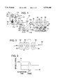
- FIG. 2 on a larger scale compared to FIG. 1, is a schematic representation of certain infeed, separating, and transfer rollers shown in FIG. 1, as used to separate a continuous web into separate web segments, which may be then interleaved.
- FIG. 3 is a graph of time versus rotational speed for a motor driving the separating rollers when used as shown in FIG. 2.
- FIG. 4 on a larger scale compared to FIG. 1, is a schematic representation of a winding turret of the winder, together with mechanisms included in the winder for driving plural winding spindles mounted operatively on the winding turret.
- certain pulleys are shown fragmentarily so as to reveal other pulleys, which would be otherwise concealed.
- FIG. 5, on a larger scale compared to FIG. 4, is a sectional detail taken along line 5--5 of FIG. 4, in a direction indicated by arrows.
- FIG. 6 is a graph of winding torque, winding tension, and spindle rotational speed (in revolutions per minute) versus roll diameter for the winder when used to wind a continuous web or interleaved web segments into a roll.
- a winder 10 for winding continuous webs or interleaved web segments into rolls constitutes a preferred embodiment of this invention.
- the winder 10 is similar to the winding an interleaving apparatus disclosed in Lotto et al. U.S. Pat. No. 5,197,727, the disclosure of which is incorporated herein by reference.
- the winder 10 comprises a winding turret 12 indexable about a center shaft 14, which defines a winding turret axis, through an endless series of four indexed positions.
- the winder 10 also comprises four winding spindles mounted operatively on the winding turret 12.
- the winding spindles may be consecutively numbered for convenient reference. As shown in FIG. 1, a first winding spindle 22 is located in what may be conveniently called an initial transfer position and a second winding spindle 24 is located in what may be conveniently called a final wind position. Moreover, a third winding spindle 26 is located in what may be conveniently called a push-off position and a fourth winding spindle 28 is located in what may be conveniently called an idle spindle position.
- the winding turret 12 is indexable from a first indexed position, in which it is shown in FIG. 1, into a second indexed position.
- first winding spindle 22 is moved from the initial transfer position into the final wind position and the second winding spindle 24 is moved from the final wind position into the push-off position.
- third winding spindle 26 is moved from the push-off position into the idle spindle position and the fourth winding spindle 28 is moved from the idle spindle position into the initial transfer position.
- the winding turret 12 is indexable from the second indexed position into a third indexed position, in which the fourth winding spindle 28 is moved from the initial transfer position into the final wind position and so on.
- the winding turret 12 is indexable from the third indexed position into a fourth indexed position, in which the third winding spindle 26 is moved from the initial transfer position into the final wind position and so on, and from the fourth indexed position into the first indexed position.
- a kick roller 18 and other means (not shown) outside the scope of this invention are used, in a known manner, to transfer a leading edge of a continuous web onto whichever one of the winding spindles is located in the initial transfer position, whereupon the same one of the winding spindles is driven rotatably so as to begin to wind the continuous web into a roll.
- a programmable controller C is programmed to control the same one of the winding spindles in the initial transfer position and in the final wind position. After a few turns, the winding turret 12 is indexed so as to move same one of the winding spindles from the initial transfer position into the final wind position, at which winding of the continuous web into a roll on the same one of the winding spindles is completed.
- the winding turret 12 is indexed so as to move the same one of the winding spindles from the final wind position into the push-off position, at which a push-off palm 20 is operated to push the completed roll off the same one of the winding spindles.
- the position occupied by the third winding spindle 26 in FIG. 1 may be conveniently called a roll-taping position, rather than a push-off position, and the position occupied by the fourth winding spindle 28 in FIG. 1 may be conveniently called a push-off position, rather than an idle spindle position.
- a taping mechanism (not shown) outside the scope of this invention is operable to apply a tape, such as a paper tape, onto a completed roll in the rolltaping position.
- a push-off palm similar to the push-off palm 20 is operable to push the completed, taped roll off the associated winding spindle in the push-off position of the alternative embodiment.
- a continuous web W is being wound into a roll R on the second winding spindle 24, in the final wind position.
- a partial roll R p comprised of a few turns is shown in broken lines on the first winding spindle 22, in the initial transfer position.
- a complete roll R c is shown in broken lines on the third winding spindle 26, in the push-off position where the push-off palm 20 can push the complete roll R c off the third winding spindle 26.
- the continuous web W is fed to the winding turret 12 through a pair of infeed rollers, a pair of separating rollers, and a pair of transfer rollers.
- the infeed rollers are comprised of a driving roller 30 and a driven roller 32.
- the driving roller 30 is driven by a frequency-controlled, alternating current motor 34, which is coupled to the driving roller 30 and on which an encoder 36 is mounted.
- the encoder 36 is arranged to count revolutions per unit time for measuring the rotational speed of the motor 34.
- the separating rollers are comprised of a driving roller 40 and a driven roller 42.
- the driving roller 40 is driven by a servo-controlled, alternating current motor 44, which is coupled to the driving roller 40 and on which an encoder 46 is mounted.
- the encoder 46 is arranged to count revolutions per unit time for measuring the rotational speed of the motor 44.
- the transfer rollers are comprised of a driving roller 50 and a driven roller 52.
- the driving roller 50 is driven by a frequency-controlled, alternating current motor 54, which is coupled to the driving roller 50 and on which an encoder 56 is mounted for measuring the rotational speed of the motor 54.
- the controller C is arranged for receiving signals from the encoders 36, 46, 56 and for controlling the motors 34, 44, 54.
- the controller C is programmed for controlling the motors 34, 54, so that the infeed rollers 30, 32, and the transfer rollers 50, 52, are driven at the same peripheral speeds, if a continuous web is involved, or at comparatively higher peripheral speeds for the infeed rollers 30, 32, and comparatively lower peripheral speeds for the transfer rollers 50, 52, if separate web segments are involved.
- the controller C is programmed for controlling the motor 44 so that the separating rollers 40, 42, are driven at peripheral speeds equal to the peripheral speeds of the infeed rollers 30, 32, except when it is desired to separate the continuous web W into a series of separate web segments S (one shown) that can be then interleaved, at cross perforations in the continuous web W, as shown in FIG. 2.
- the controller C is programmed for increasing the rotational speed of the motor 44 by a suitable percentage (X%) for a brief interval of separation time, as graphed in FIG. 3, when it is desired to do so.
- the infeed rollers 30, 32 remain in continuous rolling contact with the continuous web before its separation into separate web segments S. Except where the continuous web is separated at cross perforations, the separating rollers 40, 42, and the transfer rollers 50, 52, remain in continuous rolling contact with the series of separate web segments S.
- Suitable means (not shown) outside the scope of this invention are employed to guide the series of separate web segments S between the infeed rollers 30, 32, and the separating rollers 40, 42, between the separating rollers 40, 42, and the transfer rollers 50, 52, and downstream from the transfer rollers 50, 52.
- suitable means (not shown) outside the scope of this invention may be then employed for interleaving the series of separated web segments S before the interleaved web segments S reach the winding turret 12.
- Each of the winding spindles 22, 24, 26, 28, has a pulley-mounting portion and a web-winding portion, which is adapted to receive a continuous web or interleaved web segments for winding into a roll.
- the first winding spindle 22 has a pulley-mounting portion 60 and a web-winding portion 62.
- a pulley 64 is mounted on the pulley-mounting portion 60 and is keyed to the pulley-mounting portion 60, via a key 66, so as to be conjointly rotatable with the first winding spindle 22 and so as to be comparatively nearer to the web-winding portion 62.
- a pulley 68 is mounted on the pulley-mounting portion 60, via a pulley or ball bearing 70, so as to be independently rotatable on the first winding spindle 22 and so as to be comparatively farther from the web-winding portion 62.
- the second winding spindle 24 has a pulley-mounting portion 80 and a web-winding portion 82.
- a pulley 84 is mounted on the pulley-mounting portion 80 and is keyed to the pulley-mounting portion 80, via a key 86, so as to be conjointly rotatable with the second winding spindle 24 and so as to be comparatively farther from the web-mounting portion 82.
- a pulley 88 is mounted on the pulley-mounting portion 80, via a pulley or ball bearing 90, so as to be independently rotatable on the second winding spindle 24 and so as to be comparatively nearer to the web-mounting portion 82.
- the third winding spindle 26 has a pulley-mounting portion (not shown) and a web-mounting portion 102.
- the pulley-mounting portion of the third winding spindle 26 mounts a pulley (not shown) similar to the conjointly rotatable pulley 64 and mounted similarly so as to be conjointly rotatable with the third winding spindle 26 and so as to be comparatively nearer to the web-mounting portion 102.
- the pulleymounting portion thereof mounts a independently rotatable pulley (not shown) similar to the pulley 68 and mounted similarly so as to be independently rotatable on the third winding spindle 26 and so as to be comparatively farther from the web-mounting portion 102.
- the fourth winding spindle 28 has a pulley-mounting portion (not shown) and a web-mounting portion 112.
- the pulley-mounting portion of the fourth winding spindle 28 mounts a pulley (not shown) similar to the conjointly rotatable pulley 64 and mounted similarly so as to be conjointly rotatable with the fourth winding spindle 28 and so as to be comparatively farther from the web-mounting portion 112.
- the pulleymounting portion thereof mounts a pulley (not shown) similar to the independently rotatable pulley 68 and mounted similarly so as to be independently rotatable on the fourth winding spindle 28 and so as to be comparatively nearer to the webmounting portion 112.
- a first timing belt 120 which is toothed, is deployed around a driving pulley 122 and several driven pulleys 124 so as to interengage with two pulleys at each indexed position of the winding turret 12.
- a motor 136 preferably a servo-controlled, alternating current motor, is arranged for driving the driving pulley 122, which drives the first timing belt 120.
- a second timing belt 130 which is toothed, is deployed around a driving pulley 132 and several driven pulleys 134 so as to interengage with two pulleys at each indexed position of the winding turret 12.
- a servo-controlled, alternating current motor 126 is arranged for driving the driving pulley 132, which drives the second timing belt 130.
- the first timing belt 120 interengages with whichever one of the pulleys mounted on the pulleymounting portion of the winding spindle located in the initial transfer position is nearer to the web-winding portion thereof and with whichever one of the pulleys mounted on the pulley-mounting portion of the winding spindle located in the final wind position is nearer to the web-winding portion thereof.
- the second timing belt 130 interengages with whichever one of the pulleys mounted on the pulley-mounting portion of the winding spindle located in the initial transfer position is farther from the webwinding portion thereof and with whichever one of the pulleys mounted on the pulley-mounting portion of the winding spindle located in the final wind position is farther from the web-winding portion thereof.
- the first timing belt 120 interengages with the conjointly rotatable pulley 64 mounted on the pulley-mounting portion 60 of the first winding spindle 22, in the initial transfer position, and with the independently rotatable pulley 88 mounted on the pulley-mounting portion 80 of the second winding spindle 24, in the final wind position.
- the second timing belt 130 interengages with the independently rotatable pulley 68 mounted on the pulley-mounting portion 60 of the first winding spindle 22, in the initial transfer position, and with the conjointly rotatable pulley 84 mounted on the pulley-mounting portion 80 of the second winding spindle 24, in the final wind position.
- the winding spindle located in the initial transfer position is driven rotatably by whichever one of the timing belts is interengaged with the conjointly rotatable pulley mounted on the pulley-mounting portion of the winding spindle located in the initial transfer position.
- the first timing belt 120 interengaging with the conjointly rotatable pulley 64 mounted on the pulley-mounting portion 60 of the first winding spindle 22, in the initial transfer position, and with the independently rotatable pulley 88 mounted on the pulley-mounting portion 80 of the second winding spindle 24, in the final wind position, is driven by the motor 136 and drives the first winding spindle 22 rotatably in the initial transfer position while the pulley 88 rotates freely.
- the first timing belt 120 continues to drive the first winding spindle 22.
- the first timing belt 120 is employed to drive the third winding spindle 26.
- the second timing belt 130 is employed to drive the winding spindle being employed.
- the continuous web W or the series of interleaved web segments is conveyed to the winding turret 12 by a web conveyor 150 comprising a driving pulley 152, a driven pulley 154, an endless conveyor belt 156 deployed around the conveyor pulleys 152, 154, and a motor 158 having a drive shaft 160 coupled to the driving pulley 152 by an endless drive belt 162 for driving the web conveyor 150 at a measurable, peripheral speed.
- an encoder 164 counting revolutions per unit time is arranged for measuring the rotational speed of the first winding spindle 22 and for sending signals to the controller C.
- an encoder 166 counting revolutions per unit time is arranged for measuring the rotational speed of the second winding spindle 24 and for sending signals to the controller C.
- a similar encoder is arranged for measuring the rotational speed of the third winding spindle 26 and for sending signals to the controller C.
- a similar encoder is arranged for measuring the rotational speed of the fourth winding spindle 28 and for sending signals to the controller C.
- an encoder 172 counting revolutions per unit time is arranged for measuring the rotational speed of the drive shaft 160 of the motor 158 driving the web conveyor 150, as an indirect measure of the peripheral speed of the web conveyor 156, and for sending signals to the controller C.
- an encoder 174 counting revolutions per unit time is arranged for measuring the rotational speed of one of the conveyor pulleys 152, 154, preferably the driving pulley 152, as an indirect measure of the peripheral speed of the web conveyor 156, and for sending signals to the controller C.
- an encoder 178 counting revolutions per unit time is arranged for measuring the rotational speed of the motor driving the first timing belt 120, as an indirect measurement of the rotational speed of the winding spindle being driven by the first timing belt 120.
- an encoder 176 counting revolutions per unit time is arranged for measuring the rotational speed of the motor driving the second timing belt 130, as an indirect measurement of the rotational speed of the winding spindle being driven by the second timing belt 130.
- the controller C is programmed for controlling the motor driving whichever of the timing belts is driving the winding spindle that is being employed at any given time for winding a continuous web or a series of interleaved web segments, so as to maintain a generally constant winding tension on the continuous web or on the series of interleaved web segments.
- the relationships among the winding torque, the winding tension, and the rotational speed of the winding spindle are shown graphically in FIG. 6.
- the controller C is programmed for controlling the motor 158 driving the web conveyor 150, so as to maintain a generally constant winding tension on the continuous web or on the series of interleaved web segments.
Landscapes
- Engineering & Computer Science (AREA)
- Mechanical Engineering (AREA)
- Replacement Of Web Rolls (AREA)
- Controlling Rewinding, Feeding, Winding, Or Abnormalities Of Webs (AREA)
- Winding Of Webs (AREA)
- Making Paper Articles (AREA)
Priority Applications (7)
| Application Number | Priority Date | Filing Date | Title |
|---|---|---|---|
| US08/730,857 US5779180A (en) | 1996-10-18 | 1996-10-18 | Winder for use with bag-making machine |
| CA002216677A CA2216677A1 (en) | 1996-10-18 | 1997-09-29 | Winder for use with bag-making machine |
| EP97117796A EP0837020B1 (de) | 1996-10-18 | 1997-10-14 | Wickler zum Gebrauch mit einer Beutelherstellungsmaschine |
| DE69721435T DE69721435T2 (de) | 1996-10-18 | 1997-10-14 | Wickler zum Gebrauch mit einer Beutelherstellungsmaschine |
| ES97117796T ES2197964T3 (es) | 1996-10-18 | 1997-10-14 | Bobinadora para utilizar con una maquina de fabricar bolsas. |
| AU41876/97A AU733667B2 (en) | 1996-10-18 | 1997-10-16 | Winder for use with bag making machine |
| JP9286659A JPH10129906A (ja) | 1996-10-18 | 1997-10-20 | 袋製造機用ワインダ |
Applications Claiming Priority (1)
| Application Number | Priority Date | Filing Date | Title |
|---|---|---|---|
| US08/730,857 US5779180A (en) | 1996-10-18 | 1996-10-18 | Winder for use with bag-making machine |
Publications (1)
| Publication Number | Publication Date |
|---|---|
| US5779180A true US5779180A (en) | 1998-07-14 |
Family
ID=24937076
Family Applications (1)
| Application Number | Title | Priority Date | Filing Date |
|---|---|---|---|
| US08/730,857 Expired - Fee Related US5779180A (en) | 1996-10-18 | 1996-10-18 | Winder for use with bag-making machine |
Country Status (7)
| Country | Link |
|---|---|
| US (1) | US5779180A (de) |
| EP (1) | EP0837020B1 (de) |
| JP (1) | JPH10129906A (de) |
| AU (1) | AU733667B2 (de) |
| CA (1) | CA2216677A1 (de) |
| DE (1) | DE69721435T2 (de) |
| ES (1) | ES2197964T3 (de) |
Cited By (22)
| Publication number | Priority date | Publication date | Assignee | Title |
|---|---|---|---|---|
| US6364241B1 (en) | 1999-08-27 | 2002-04-02 | Fas Converting Machinery, Ab | Apparatus and method of producing rolls of bags |
| US20030236157A1 (en) * | 2002-06-19 | 2003-12-25 | Contour Fabricators, Inc. | Methods and apparatus for folding sheet material |
| US6746389B2 (en) | 1997-10-31 | 2004-06-08 | Cmd Corporation | Method and apparatus for folding or separating bags |
| US6761329B2 (en) | 1999-08-27 | 2004-07-13 | Fas Converting Machinery Ab | Apparatus and method of producing rolls of bags |
| US20050150989A1 (en) * | 2002-04-15 | 2005-07-14 | Georg Pfeifer | Device for storing bags |
| US20050211818A1 (en) * | 2004-03-26 | 2005-09-29 | The Hudson-Sharp Machine Co. | Winder apparatus with transfer brush roll |
| US20070045464A1 (en) * | 2005-08-31 | 2007-03-01 | Mcneil Kevin B | Process for winding a web material |
| US20070045462A1 (en) * | 2005-08-31 | 2007-03-01 | Mcneil Kevin B | Hybrid winder |
| US20070102560A1 (en) * | 2005-11-04 | 2007-05-10 | Mcneil Kevin B | Process for winding a web material |
| US20070102559A1 (en) * | 2005-11-04 | 2007-05-10 | Mcneil Kevin B | Rewind system |
| US20070215741A1 (en) * | 2006-03-17 | 2007-09-20 | The Procter & Gamble Company | Process for rewinding a web material |
| US20070215740A1 (en) * | 2006-03-17 | 2007-09-20 | The Procter & Gamble Company | Apparatus for rewinding web materials |
| US20110017860A1 (en) * | 2009-07-24 | 2011-01-27 | Jeffrey Moss Vaughn | Process for winding a web material |
| US20110017859A1 (en) * | 2009-07-24 | 2011-01-27 | Jeffrey Moss Vaughn | hybrid winder |
| US20110209818A1 (en) * | 2010-02-26 | 2011-09-01 | Bittner Dale F | Winding Method and Apparatus |
| CN105621131A (zh) * | 2016-03-25 | 2016-06-01 | 浙江超伟机械有限公司 | 一种重叠塑胶袋收卷装置 |
| WO2017151998A1 (en) | 2016-03-04 | 2017-09-08 | The Procter & Gamble Company | A leading edge device for a surface winder |
| WO2017152006A1 (en) | 2016-03-04 | 2017-09-08 | The Procter & Gamble Company | An introductory portion for a surface winder |
| US9809417B2 (en) | 2015-08-14 | 2017-11-07 | The Procter & Gamble Company | Surface winder |
| US20180169990A1 (en) * | 2011-04-20 | 2018-06-21 | Cmd Corporation | Method and Apparatus For Making Bags |
| US10033064B2 (en) | 2014-06-24 | 2018-07-24 | Duracell U.S. Operations, Inc. | Method and apparatus for forming a wound structure |
| US10442649B2 (en) | 2016-03-04 | 2019-10-15 | The Procter & Gamble Company | Surface winder for producing logs of convolutely wound web materials |
Families Citing this family (8)
| Publication number | Priority date | Publication date | Assignee | Title |
|---|---|---|---|---|
| EP1281649A1 (de) * | 2001-08-03 | 2003-02-05 | FAS Converting Machinery AB | Vorrichtung und Verfahren zur Produktion von Rollen von Beuteln |
| US20090019817A1 (en) * | 2006-09-14 | 2009-01-22 | Cmd Corporation | Bag Machine And Winder |
| CN101224592B (zh) * | 2008-01-29 | 2011-04-13 | 丰县兴龙元丝塑料编织厂 | 网眼袋圆织机收卷料装置 |
| IT1402104B1 (it) * | 2010-10-08 | 2013-08-28 | Amutec S R L Con Socio Unico | Una sezione di avvolgimento per la produzione automatizzata di rotoli di buste. |
| EP2517992A1 (de) * | 2011-04-27 | 2012-10-31 | Atlas Converting Equipment Limited | Bahnwickelmaschinen und/oder Verfahren zum Betrieb von Bahnwickelmaschinen |
| CN109279401A (zh) * | 2018-11-06 | 2019-01-29 | 苏州极数印花科技有限公司 | 一种高速多通道印刷机收纸系统的导轨结构 |
| CN112057636B (zh) * | 2020-08-24 | 2022-11-15 | 徐州市康农消毒技术研究院有限公司 | 一种保洁工作服消毒装置 |
| KR102308578B1 (ko) * | 2021-05-31 | 2021-10-06 | (주)한길패키지 | 포장대 제조장치에 구비되는 절취장치 및 이를 구비한 포장대 제조장치 |
Citations (20)
| Publication number | Priority date | Publication date | Assignee | Title |
|---|---|---|---|---|
| US2995314A (en) * | 1958-03-27 | 1961-08-08 | Paper Converting Machine Co | Web winding apparatus |
| US3881665A (en) * | 1973-12-28 | 1975-05-06 | Wavin Bv | Device for producing roll-shaped packets of bags of plastic |
| US3930620A (en) * | 1974-04-18 | 1976-01-06 | Compensating Tension Controls Inc. | Turret rewinder |
| US4069986A (en) * | 1976-11-02 | 1978-01-24 | Egan Machinery Company | Flying transfer winder driver |
| US4642084A (en) * | 1984-08-17 | 1987-02-10 | Custom Machinery Design, Inc. | Plastic bag making machine |
| US4667890A (en) * | 1985-07-15 | 1987-05-26 | Custom Machinery Design, Inc. | Coreless winder |
| US4695005A (en) * | 1985-05-13 | 1987-09-22 | Custom Machinery Design, Inc. | Coreless winder for strips of pliable material |
| US4729521A (en) * | 1985-04-16 | 1988-03-08 | Mitsubishi Jukogyo Kabushiki Kaisha | Controller for winding unvulcanized rubber sheet |
| US4883233A (en) * | 1987-05-20 | 1989-11-28 | Valmet Paper Machinery, Inc. | Method for controlling the reeling of a web |
| US5161793A (en) * | 1991-02-06 | 1992-11-10 | Fmc Corporation | Interleaving apparatus for rolled up segments |
| US5197727A (en) * | 1991-02-06 | 1993-03-30 | Fmc Corporation | Interleaving apparatus for rolled up segments |
| EP0568253A1 (de) * | 1992-05-01 | 1993-11-03 | Cmd Corporation | Verfahren und Vorrichtung zum Überlappen von Plastikbeuteln |
| JPH05338883A (ja) * | 1992-06-11 | 1993-12-21 | Yaskawa Electric Corp | 巻出しコイルの初期径検出方法 |
| US5318237A (en) * | 1992-10-08 | 1994-06-07 | Fmc Corporation | Air horn for web winding machine |
| US5337968A (en) * | 1990-04-04 | 1994-08-16 | Fmc Corporation | Apparatus for rolling up web material |
| US5350928A (en) * | 1993-02-11 | 1994-09-27 | Fmc Corporation | Apparatus and method for detecting perforations |
| US5362013A (en) * | 1992-05-01 | 1994-11-08 | Custom Machinery Design, Inc. | Method and apparatus for interleaving plastic bags |
| US5390875A (en) * | 1992-05-01 | 1995-02-21 | Cmd Corporation | Method and apparatus for interleaving plastic bags |
| US5453070A (en) * | 1994-07-12 | 1995-09-26 | James River Paper Company, Inc. | System for manufacturing coreless roll paper products |
| US5531660A (en) * | 1995-01-18 | 1996-07-02 | Reynolds Consumer Products Inc. | Bag folding apparatus |
Family Cites Families (9)
| Publication number | Priority date | Publication date | Assignee | Title |
|---|---|---|---|---|
| US3116890A (en) * | 1961-08-01 | 1964-01-07 | Paper Converting Machine Co | Web winding apparatus |
| EP0054735B1 (de) * | 1980-12-23 | 1985-01-16 | Windmöller & Hölscher | Vorrichtung zum Herstellen von Schuppenbandrollen aus geschuppt Übereinander abgelegten flachen flexiblen Gegenständen |
| CH659233A5 (de) * | 1983-01-21 | 1987-01-15 | Grapha Holding Ag | Vorrichtung zum aufwickeln eines schuppenstromes aus papierbogen. |
| CH657833A5 (de) * | 1983-09-19 | 1986-09-30 | Ferag Ag | Verfahren und vorrichtung zum bilden von mehrlagigen wickeln aus in schuppenformation anfallenden flaechigen, biegsamen erzeugnissen, vorzugsweise druckprodukten. |
| US4588138A (en) * | 1984-06-29 | 1986-05-13 | Paper Converting Machine Company | Web winding machine |
| GB2211824B (en) * | 1987-11-02 | 1992-04-22 | Imprinting Systems Specialty I | Label auto-transfer turret rewind assembly |
| IT215262Z2 (it) * | 1988-11-21 | 1990-09-11 | Meschi Ind Grafica | Strapperina per nastri di materiali in fogli come nastri di carta. |
| US5141142A (en) * | 1989-08-28 | 1992-08-25 | Pitney Bowes Inc. | Method and apparatus for bursting perforated web material |
| JPH0678142B2 (ja) * | 1989-12-27 | 1994-10-05 | 禎美 伊藤 | 帯状部材の巻取り装置 |
-
1996
- 1996-10-18 US US08/730,857 patent/US5779180A/en not_active Expired - Fee Related
-
1997
- 1997-09-29 CA CA002216677A patent/CA2216677A1/en not_active Abandoned
- 1997-10-14 EP EP97117796A patent/EP0837020B1/de not_active Expired - Lifetime
- 1997-10-14 DE DE69721435T patent/DE69721435T2/de not_active Expired - Fee Related
- 1997-10-14 ES ES97117796T patent/ES2197964T3/es not_active Expired - Lifetime
- 1997-10-16 AU AU41876/97A patent/AU733667B2/en not_active Ceased
- 1997-10-20 JP JP9286659A patent/JPH10129906A/ja active Pending
Patent Citations (23)
| Publication number | Priority date | Publication date | Assignee | Title |
|---|---|---|---|---|
| US2995314A (en) * | 1958-03-27 | 1961-08-08 | Paper Converting Machine Co | Web winding apparatus |
| US3881665A (en) * | 1973-12-28 | 1975-05-06 | Wavin Bv | Device for producing roll-shaped packets of bags of plastic |
| US3930620A (en) * | 1974-04-18 | 1976-01-06 | Compensating Tension Controls Inc. | Turret rewinder |
| US4069986A (en) * | 1976-11-02 | 1978-01-24 | Egan Machinery Company | Flying transfer winder driver |
| US4642084A (en) * | 1984-08-17 | 1987-02-10 | Custom Machinery Design, Inc. | Plastic bag making machine |
| US4729521A (en) * | 1985-04-16 | 1988-03-08 | Mitsubishi Jukogyo Kabushiki Kaisha | Controller for winding unvulcanized rubber sheet |
| US4695005A (en) * | 1985-05-13 | 1987-09-22 | Custom Machinery Design, Inc. | Coreless winder for strips of pliable material |
| US4667890A (en) * | 1985-07-15 | 1987-05-26 | Custom Machinery Design, Inc. | Coreless winder |
| US4883233A (en) * | 1987-05-20 | 1989-11-28 | Valmet Paper Machinery, Inc. | Method for controlling the reeling of a web |
| US5337968A (en) * | 1990-04-04 | 1994-08-16 | Fmc Corporation | Apparatus for rolling up web material |
| US5197727A (en) * | 1991-02-06 | 1993-03-30 | Fmc Corporation | Interleaving apparatus for rolled up segments |
| US5161793A (en) * | 1991-02-06 | 1992-11-10 | Fmc Corporation | Interleaving apparatus for rolled up segments |
| US5570878A (en) * | 1991-02-06 | 1996-11-05 | Fmc Corporation | Interleaving apparatus for rolled-up segments |
| US5588644A (en) * | 1991-02-06 | 1996-12-31 | Fmc Corporation | Interleaving apparatus for rolled up segments |
| EP0568253A1 (de) * | 1992-05-01 | 1993-11-03 | Cmd Corporation | Verfahren und Vorrichtung zum Überlappen von Plastikbeuteln |
| US5362013A (en) * | 1992-05-01 | 1994-11-08 | Custom Machinery Design, Inc. | Method and apparatus for interleaving plastic bags |
| US5377929A (en) * | 1992-05-01 | 1995-01-03 | Custom Machinery Design, Inc. | Method and apparatus for interleaving plastic bags |
| US5390875A (en) * | 1992-05-01 | 1995-02-21 | Cmd Corporation | Method and apparatus for interleaving plastic bags |
| JPH05338883A (ja) * | 1992-06-11 | 1993-12-21 | Yaskawa Electric Corp | 巻出しコイルの初期径検出方法 |
| US5318237A (en) * | 1992-10-08 | 1994-06-07 | Fmc Corporation | Air horn for web winding machine |
| US5350928A (en) * | 1993-02-11 | 1994-09-27 | Fmc Corporation | Apparatus and method for detecting perforations |
| US5453070A (en) * | 1994-07-12 | 1995-09-26 | James River Paper Company, Inc. | System for manufacturing coreless roll paper products |
| US5531660A (en) * | 1995-01-18 | 1996-07-02 | Reynolds Consumer Products Inc. | Bag folding apparatus |
Non-Patent Citations (5)
| Title |
|---|
| CMD Corporation, Cordless/Core Winders Brochure Appleton, WI, Oct., 1993. * |
| FMC Corporation, M 350 Winder Product Brochure , Green Bay, WI, 1992. * |
| FMC Corporation, M 450 Continuous Motion Winder Product Brochure , Green Bay, WI, Jul. 1996. * |
| FMC Corporation, M-350 Winder Product Brochure, Green Bay, WI, 1992. |
| FMC Corporation, M-450 Continuous Motion Winder Product Brochure, Green Bay, WI, Jul. 1996. |
Cited By (42)
| Publication number | Priority date | Publication date | Assignee | Title |
|---|---|---|---|---|
| US6746389B2 (en) | 1997-10-31 | 2004-06-08 | Cmd Corporation | Method and apparatus for folding or separating bags |
| US20080200323A1 (en) * | 1997-10-31 | 2008-08-21 | Cmd Corporation | Method And Apparatus For Folding Or Separate Bags |
| US20060229182A1 (en) * | 1997-10-31 | 2006-10-12 | Cmd Corporation | Method And Apparatus For Folding Or Separate Bags |
| US6364241B1 (en) | 1999-08-27 | 2002-04-02 | Fas Converting Machinery, Ab | Apparatus and method of producing rolls of bags |
| US6761329B2 (en) | 1999-08-27 | 2004-07-13 | Fas Converting Machinery Ab | Apparatus and method of producing rolls of bags |
| US20050150989A1 (en) * | 2002-04-15 | 2005-07-14 | Georg Pfeifer | Device for storing bags |
| US7360737B2 (en) * | 2002-04-15 | 2008-04-22 | Optima Filling And Packaging Machines Gmbh | Device for storing bags |
| US20030236157A1 (en) * | 2002-06-19 | 2003-12-25 | Contour Fabricators, Inc. | Methods and apparatus for folding sheet material |
| US6723036B2 (en) * | 2002-06-19 | 2004-04-20 | Contour Fabricators, Inc. | Methods and apparatus for folding sheet material |
| US20050211818A1 (en) * | 2004-03-26 | 2005-09-29 | The Hudson-Sharp Machine Co. | Winder apparatus with transfer brush roll |
| US7108219B2 (en) * | 2004-03-26 | 2006-09-19 | Hudson-Sharp Machine Company | Winder apparatus with transfer brush roll |
| US20070045462A1 (en) * | 2005-08-31 | 2007-03-01 | Mcneil Kevin B | Hybrid winder |
| US20070045464A1 (en) * | 2005-08-31 | 2007-03-01 | Mcneil Kevin B | Process for winding a web material |
| US7455260B2 (en) | 2005-08-31 | 2008-11-25 | The Procter & Gamble Company | Process for winding a web material |
| US7392961B2 (en) | 2005-08-31 | 2008-07-01 | The Procter & Gamble Company | Hybrid winder |
| US9365378B2 (en) | 2005-11-04 | 2016-06-14 | The Procter & Gamble Company | Rewind system |
| US20070102559A1 (en) * | 2005-11-04 | 2007-05-10 | Mcneil Kevin B | Rewind system |
| US7546970B2 (en) | 2005-11-04 | 2009-06-16 | The Procter & Gamble Company | Process for winding a web material |
| US20070102560A1 (en) * | 2005-11-04 | 2007-05-10 | Mcneil Kevin B | Process for winding a web material |
| US8800908B2 (en) | 2005-11-04 | 2014-08-12 | The Procter & Gamble Company | Rewind system |
| US20070215740A1 (en) * | 2006-03-17 | 2007-09-20 | The Procter & Gamble Company | Apparatus for rewinding web materials |
| US20070215741A1 (en) * | 2006-03-17 | 2007-09-20 | The Procter & Gamble Company | Process for rewinding a web material |
| US7559503B2 (en) | 2006-03-17 | 2009-07-14 | The Procter & Gamble Company | Apparatus for rewinding web materials |
| US8459586B2 (en) | 2006-03-17 | 2013-06-11 | The Procter & Gamble Company | Process for rewinding a web material |
| US20110017860A1 (en) * | 2009-07-24 | 2011-01-27 | Jeffrey Moss Vaughn | Process for winding a web material |
| US20110017859A1 (en) * | 2009-07-24 | 2011-01-27 | Jeffrey Moss Vaughn | hybrid winder |
| US8157200B2 (en) | 2009-07-24 | 2012-04-17 | The Procter & Gamble Company | Process for winding a web material |
| US8162251B2 (en) | 2009-07-24 | 2012-04-24 | The Procter & Gamble Company | Hybrid winder |
| US8851137B2 (en) * | 2010-02-26 | 2014-10-07 | The Procter & Gamble Company | Winding method and apparatus |
| US20110209818A1 (en) * | 2010-02-26 | 2011-09-01 | Bittner Dale F | Winding Method and Apparatus |
| US9434565B2 (en) | 2010-02-26 | 2016-09-06 | Duracell U.S. Operations, Inc. | Winding method |
| US10183825B2 (en) | 2010-02-26 | 2019-01-22 | Duracell U.S. Operations, Inc. | Winding method |
| US10933604B2 (en) * | 2011-04-20 | 2021-03-02 | Cmd Corporation | Method and apparatus for making bags |
| US20180169990A1 (en) * | 2011-04-20 | 2018-06-21 | Cmd Corporation | Method and Apparatus For Making Bags |
| US10033064B2 (en) | 2014-06-24 | 2018-07-24 | Duracell U.S. Operations, Inc. | Method and apparatus for forming a wound structure |
| US9809417B2 (en) | 2015-08-14 | 2017-11-07 | The Procter & Gamble Company | Surface winder |
| WO2017151998A1 (en) | 2016-03-04 | 2017-09-08 | The Procter & Gamble Company | A leading edge device for a surface winder |
| WO2017152006A1 (en) | 2016-03-04 | 2017-09-08 | The Procter & Gamble Company | An introductory portion for a surface winder |
| US10427903B2 (en) | 2016-03-04 | 2019-10-01 | The Procter & Gamble Company | Leading edge device for a surface winder |
| US10427902B2 (en) | 2016-03-04 | 2019-10-01 | The Procter & Gamble Company | Enhanced introductory portion for a surface winder |
| US10442649B2 (en) | 2016-03-04 | 2019-10-15 | The Procter & Gamble Company | Surface winder for producing logs of convolutely wound web materials |
| CN105621131A (zh) * | 2016-03-25 | 2016-06-01 | 浙江超伟机械有限公司 | 一种重叠塑胶袋收卷装置 |
Also Published As
| Publication number | Publication date |
|---|---|
| AU733667B2 (en) | 2001-05-24 |
| AU4187697A (en) | 1998-04-23 |
| EP0837020B1 (de) | 2003-05-02 |
| DE69721435T2 (de) | 2004-03-11 |
| EP0837020A3 (de) | 1999-01-07 |
| CA2216677A1 (en) | 1998-04-18 |
| DE69721435D1 (de) | 2003-06-05 |
| ES2197964T3 (es) | 2004-01-16 |
| JPH10129906A (ja) | 1998-05-19 |
| EP0837020A2 (de) | 1998-04-22 |
Similar Documents
| Publication | Publication Date | Title |
|---|---|---|
| US5779180A (en) | Winder for use with bag-making machine | |
| JP2614488B2 (ja) | 貯蔵装置 | |
| CA1240655A (en) | Form burster | |
| US6715709B2 (en) | Apparatus and method for producing logs of sheet material | |
| US5746869A (en) | Apparatus and process for cyclically accelerating and decelerating a strip of material | |
| US5794929A (en) | Variable velocity profile decelleration device | |
| SE451261B (sv) | Anordning for att dubbelvika en flexibel produkt | |
| GB1388665A (en) | Paper supplying device in coin-wrapping machine | |
| EP0057523B1 (de) | Längsschneidumroller | |
| US4875633A (en) | Paper splicing device | |
| JPH03180346A (ja) | 印刷機用の折り機 | |
| CA1225627A (en) | Device for splicing the laps of two reels of web material | |
| US4184392A (en) | Web cutting machines | |
| GB2121771A (en) | A method of and apparatus for storing paper sheets | |
| US5605267A (en) | Apparatus for automatically feeding the end of a web of material | |
| JPS61174054A (ja) | 包装部材供給装置における繰り出し量制御装置 | |
| JPS62295859A (ja) | 帯状ウエブの間欠給送装置 | |
| JP2000510429A (ja) | 紙ウェブの巻取装置および紙ウェブの巻取方法 | |
| JP2002035027A (ja) | 着用物品の製造設備 | |
| JPH1072148A (ja) | 連続ウェブまたは挿間ウェブ用のロール形成装置 | |
| RU2237004C1 (ru) | Перемоточная машина для намотки тонколистового материала на гильзу для рулонов и соответствующий способ намотки | |
| JPS60218250A (ja) | ウエブの張力付与方法 | |
| WO2004000651A1 (en) | Apparatus for selectively feeding a film in a packaging machine | |
| JPH0154253B2 (de) | ||
| PL182037B1 (pl) | Urzadzenie do ukladania wyrobów warstwowych PL |
Legal Events
| Date | Code | Title | Description |
|---|---|---|---|
| AS | Assignment |
Owner name: FMC CORPORATION, ILLINOIS Free format text: ASSIGNMENT OF ASSIGNORS INTEREST;ASSIGNORS:DE SMEDT. ERIC;VERBEIREN, WIM;REEL/FRAME:008361/0304 Effective date: 19970113 |
|
| AS | Assignment |
Owner name: NATIONSBANK, N.A., MARYLAND Free format text: SECURITY INTEREST;ASSIGNOR:HUDSON-SHARP MACHINE COMPANY, THE;REEL/FRAME:009367/0669 Effective date: 19980714 Owner name: NATIONSBANK EUROPE LIMITED, ENGLAND Free format text: SECURITY INTEREST;ASSIGNOR:HUDSON-SHARP MACHINE COMPANY, THE;REEL/FRAME:009367/0669 Effective date: 19980714 Owner name: HUDSON-SHARP MACHINE COMPANY, THE, WISCONSIN Free format text: ASSIGNMENT OF ASSIGNORS INTEREST;ASSIGNOR:FMC CORPORATION;REEL/FRAME:009386/0257 Effective date: 19980717 |
|
| AS | Assignment |
Owner name: HUDSON-SHARP MACHINE COMPANY, WISCONSIN Free format text: ASSIGNMENT OF ASSIGNORS INTEREST;ASSIGNOR:FMC CORPORATION;REEL/FRAME:009719/0883 Effective date: 19980717 |
|
| FEPP | Fee payment procedure |
Free format text: PAT HOLDER CLAIMS SMALL ENTITY STATUS, ENTITY STATUS SET TO SMALL (ORIGINAL EVENT CODE: LTOS); ENTITY STATUS OF PATENT OWNER: SMALL ENTITY |
|
| FPAY | Fee payment |
Year of fee payment: 4 |
|
| REMI | Maintenance fee reminder mailed | ||
| AS | Assignment |
Owner name: HUDSON-SHARO MACHINE COMPANY, THE, WISCONSIN Free format text: RELEASE;ASSIGNORS:NATIONSBANK, N.A.;NATIONSBANK EUROPE LIMITED;REEL/FRAME:014556/0300 Effective date: 20030714 |
|
| AS | Assignment |
Owner name: BANK ONE, N.A., WISCONSIN Free format text: ASSIGNMENT OF ASSIGNORS INTEREST;ASSIGNOR:HUDSON-SHARP MACHINE COMPANY, THE;REEL/FRAME:015271/0448 Effective date: 20030714 |
|
| FEPP | Fee payment procedure |
Free format text: PAYOR NUMBER ASSIGNED (ORIGINAL EVENT CODE: ASPN); ENTITY STATUS OF PATENT OWNER: SMALL ENTITY |
|
| FPAY | Fee payment |
Year of fee payment: 8 |
|
| AS | Assignment |
Owner name: THE HUDSON-SHARP MACHINE COMPANY, WISCONSIN Free format text: RELEASE OF COLLATERAL ASSIGNMENT OF PATENTS AS SECURITY;ASSIGNOR:JP MORGAN CHASE BANK, N.A.;REEL/FRAME:023220/0066 Effective date: 20090831 |
|
| REMI | Maintenance fee reminder mailed | ||
| LAPS | Lapse for failure to pay maintenance fees | ||
| STCH | Information on status: patent discontinuation |
Free format text: PATENT EXPIRED DUE TO NONPAYMENT OF MAINTENANCE FEES UNDER 37 CFR 1.362 |
|
| FP | Lapsed due to failure to pay maintenance fee |
Effective date: 20100714 |