US5691620A - Battery charging method - Google Patents
Battery charging method Download PDFInfo
- Publication number
- US5691620A US5691620A US08/762,300 US76230096A US5691620A US 5691620 A US5691620 A US 5691620A US 76230096 A US76230096 A US 76230096A US 5691620 A US5691620 A US 5691620A
- Authority
- US
- United States
- Prior art keywords
- battery
- charging
- batteries
- circuit
- voltage
- Prior art date
- Legal status (The legal status is an assumption and is not a legal conclusion. Google has not performed a legal analysis and makes no representation as to the accuracy of the status listed.)
- Expired - Lifetime
Links
Images


Classifications
-
- H—ELECTRICITY
- H01—ELECTRIC ELEMENTS
- H01M—PROCESSES OR MEANS, e.g. BATTERIES, FOR THE DIRECT CONVERSION OF CHEMICAL ENERGY INTO ELECTRICAL ENERGY
- H01M10/00—Secondary cells; Manufacture thereof
- H01M10/34—Gastight accumulators
-
- H—ELECTRICITY
- H01—ELECTRIC ELEMENTS
- H01M—PROCESSES OR MEANS, e.g. BATTERIES, FOR THE DIRECT CONVERSION OF CHEMICAL ENERGY INTO ELECTRICAL ENERGY
- H01M10/00—Secondary cells; Manufacture thereof
- H01M10/42—Methods or arrangements for servicing or maintenance of secondary cells or secondary half-cells
- H01M10/44—Methods for charging or discharging
-
- Y—GENERAL TAGGING OF NEW TECHNOLOGICAL DEVELOPMENTS; GENERAL TAGGING OF CROSS-SECTIONAL TECHNOLOGIES SPANNING OVER SEVERAL SECTIONS OF THE IPC; TECHNICAL SUBJECTS COVERED BY FORMER USPC CROSS-REFERENCE ART COLLECTIONS [XRACs] AND DIGESTS
- Y02—TECHNOLOGIES OR APPLICATIONS FOR MITIGATION OR ADAPTATION AGAINST CLIMATE CHANGE
- Y02E—REDUCTION OF GREENHOUSE GAS [GHG] EMISSIONS, RELATED TO ENERGY GENERATION, TRANSMISSION OR DISTRIBUTION
- Y02E60/00—Enabling technologies; Technologies with a potential or indirect contribution to GHG emissions mitigation
- Y02E60/10—Energy storage using batteries
Definitions
- the present invention relates to a battery charging method suitable for use with batteries which are used with, for example, cameras and a video tape recorders which are formed together as a single item.
- Comparatively small batteries have to be used with cameras and a video tape recorders which are formed together as a single item so as their portability is maintained. Secondary batteries which can be recharged are therefore used as these batteries.
- the charging method for these secondary batteries differs depending on their type.
- a constant current circuit and a fixed voltage circuit are used for charging lithium ion batteries.
- constant current circuits are used for charging nickel cadmium batteries. Fixed current circuits are used until completion when charging lithium ion batteries, whilst fixed voltage circuits are used until completion when charging nickel cadmium batteries. If the charging time then becomes long, the detection of full charging becomes difficult. In the worst case there is the danger that a battery may break down. Therefore, in the related art, methods have been evolved where the type of battery is determined and charging is then carried out in accordance with the battery type.
- One way of determining the battery type is to change the shape of the lithium batteries and the nickel cadmium batteries. There are also methods where electrodes are set up and the type of battery is determined using these electrodes.
- the battery shape is adapted depending on the type of the battery, the battery has to be large. Also, the charging equipment has to be prepared for each different kind of battery, which is expensive. Further, in methods which use detection electrodes, it is difficult to determine the type of the battery if connections with the electrodes are unsatisfactory.
- the present invention sets out to resolve the aforementioned problems, it purpose is to put forward a single charging apparatus in which differing types of batteries can be reliably charged.
- the same charging equipment is used to charge a first type of battery and a second type of battery, in such a manner that the terminal voltage for the first type of battery when fully charged is larger than the terminal voltage for the second type of battery when fully charged.
- a lithium ion battery may be used as the first type of battery and a nickel-cadmium battery may be used as the second type of battery.
- the types of the first and second batteries are detected and the first type of battery and the second type of battery are charged using different methods in accordance with the detection result.
- the first and second types of batteries are charged using a fixed voltage circuit and a constant current circuit and the types of the first and second batteries are determined using the magnitudes of the terminal voltages after the terminal voltages for the batteries have exceeded a prescribed standard value.
- the first and second types of batteries may be charged using a fixed voltage circuit and a constant current circuit and the types of the first and second batteries may be determined using the sizes of the terminal currents after the terminal currents for the batteries have fallen below a prescribed standard value.
- the first and second types of batteries may be charged for a predetermined period of time by a fixed voltage circuit and a constant current circuit and the types of the first and second batteries may be determined by using at least one of the magnitudes of the terminal voltages for the batteries or the magnitudes of the charging currents for the batteries.
- first and second types of batteries may be charged using a constant current circuit and the types of the first and second batteries may be determined using the rate of change of the terminal voltages after the terminal voltages for the batteries have exceeded a prescribed standard value.
- charging of the first type of battery is carried out using a fixed voltage circuit and a constant current circuit
- charging of the second type of battery is carried out using a constant current circuit
- Full charging of the first type of battery may be detected as a result of its charging current having become sufficiently small.
- the full charging of the second type of battery may be detected as a result of its terminal voltage having fallen.
- the full charging of the batteries may also be detected both as a result of the charging current for the batteries having reduced sufficiently and as a result of the terminal voltages for the batteries having become small.
- the terminal voltage for the first type of battery at the time of full charging is set beforehand to be a higher value than the terminal voltage for the second type of battery at the time of full charging. It is then possible to use the same charging equipment to reliably charge both of the batteries without causing damage.
- FIGS. 1A and 1B are a view of the structures of the batteries for the present invention.
- FIG. 2 is a block view showing the structure of a first embodiment of charging equipment suitable for use with a battery charging method for this invention
- FIG. 3 is a view showing the charging characteristics for a lithium ion battery
- FIG. 4 is a view showing the charging characteristics for a nickel cadmium battery
- FIG. 5 is a block view showing the structure of a second charging equipment embodiment
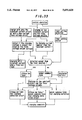
- FIG. 6 is a flowchart describing the operation of the embodiment in FIG. 5;
- FIG. 7 is a view describing the theory of determining the type of battery in step S5 in FIG. 6;
- FIG. 8 is a flowchart describing the charging method for the lithium ion battery in step S6;
- FIG. 9 is a view describing the charging which uses the method shown in the flowchart in FIG. 8;
- FIG. 10 is a flowchart describing the charging method for the nickel cadmium battery occurring in step 7 of FIG. 6;
- FIG. 11 is a block view showing the structure of a third charging equipment embodiment
- FIG. 12 is a flowchart describing the operation of the embodiment in FIG. 11;
- FIGS. 13A and 13B are a view describing the theory of the battery determination occurring in step S54 of FIG. 12;
- FIGS. 14A and 14B are a view describing a further theory for the battery determination occurring in step S54 of FIG. 12;
- FIG. 15 is a block view showing the structure of a fourth charging equipment embodiment
- FIG. 16 is a flowchart describing the operation of the embodiment in FIG. 15;
- FIG. 17 is a view describing the theory of the battery type determination occurring in step S74 in FIG. 16;
- FIG. 18 is a block view showing the structure of a fifth charging equipment embodiment
- FIG. 19 is a flowchart describing the operation of the embodiment in FIG. 18;
- FIG. 20 is a block view showing the structure of a sixth charging equipment embodiment
- FIG. 21 is a flowchart describing the operation of the embodiment in FIG. 20;
- FIG. 22 is a block view showing the structure of a seventh charging equipment embodiment
- FIG. 23 is a block view showing the structure of an eighth charging equipment embodiment
- FIG. 24 is a block view showing the structure of a ninth charging equipment embodiment
- FIG. 25 is a flowchart showing a further battery charging method for the present invention.
- FIG. 26 is a view describing the theory of the battery type determination occurring in step S134 of FIG. 25;
- FIG. 27 is a view describing a further theory for the battery type determination occurring in step S134 of FIG. 25;
- FIG. 28 is a flowchart showing another battery charging method for this invention.
- FIG. 29 is a view describing the theory of the battery type determination occurring in step S145 of FIG. 28;
- FIG. 30 is a view describing a further theory for the battery type determination occurring in step S145 of FIG. 28;
- FIG. 31 is a view describing an example combination of the battery charging methods in this invention.
- FIG. 32 is a view describing a further example combination of the battery charging methods in this invention.
- FIG. 33 is a view describing another example combination of the battery charging methods in this invention.
- FIGS. 1A and 1B show the relationship between the different types of batteries charged by the battery charging method for the present invention.
- FIG. 1(a) shows the lithium ion battery 1L which consists of "L" cells and has a terminal voltage V L when fully charged.
- This lithium ion battery 1L includes a lithium battery, a lithium ion battery and a lead battery etc.
- FIG. 1(b) shows the structure of a nickel cadmium battery 1N which is made up of a combination of N cells and has a terminal voltage V N .
- This nickel cadmium battery 1N includes a nickel cadmium battery and a nickel hydrogen battery etc.
- These batteries 1L and 1N are made to be completely the same shape so that the batteries 1 (1L, 1N) can be charged using the same charging equipment.
- FIG. 2 is a view showing an example of the structure of the charging equipment for charging the batteries L1 and L2 shown in FIG. 1.
- the prescribed electrical power is supplied to a constant current circuit 12 and a fixed voltage circuit 13 via a switch 11.
- the battery 1 (1L, 1N), which it is intended to charge, is connected to the constant current circuit 12 and the fixed voltage circuit 13, and a charging detection resistor 14 is then connected in series with this battery 1.
- a current detection circuit 15 detects the current flowing through the resistance 14 from the voltage across the terminals of this resistance 14 and this is then outputted to a control circuit 17.
- This control circuit 17 is, for example, made up from a microcomputer etc.
- a timer circuit 18 is always keeping track of time and outputs this time information to the control circuit 17.
- the control circuit 17 switches switch 11 on when charging starts and off when charging finishes.
- a voltage detection circuit 16 is connected in parallel with the battery 1. This voltage detection circuit 16 detects the terminal voltage or the charging voltage of the battery 1 and outputs the result of this detection to the control circuit 17 and a - ⁇ V detection circuit 19. The - ⁇ V detection circuit 19 then detects the reduction in the terminal voltage of the battery 1N (- ⁇ V) and outputs the detection result to the control circuit 17.
- the charging operation is generally carried out in accordance with the characteristics shown in FIG. 3.
- the fixed voltage circuit 13 is practically not in operation because the internal impedance of the battery 1L is low.
- the battery 1L is therefore charged by a constant current I 10 from the constant current circuit 12.
- the internal impedance of the battery 1L increases as the battery 1L is gradually charged and there is therefore an abrupt drop in the charging current I 1 flowing through the battery 1L.
- the constant current circuit 12 is practically not functioning and the fixed voltage circuit 13 is functioning. From thereafter the battery 1L is charged by a fixed voltage from the fixed voltage circuit 13.
- the charging current I 1 for the battery 1 gradually gets smaller as the fixed voltage charging progresses.
- the charging current I 1 flowing through the resistance 14 is detected by the charging detection circuit 15 so that when this charging current I 1 becomes lower than a prescribed standard value decided beforehand, the control circuit 17 switches the switch 11 off and the charging operation is halted.
- charging may be carried out continuously from the time when the charging current falls below a prescribed standard value set beforehand for a prescribed period of time, also set beforehand.
- the control circuit 17 turns off the switch 11 and the charging is stopped.
- the terminal voltage for the battery 1L becomes the voltage V L occurring at the time of full charging.
- the charging is carried out using the constant current I 20 from the constant current circuit 12 in the way shown in FIG. 4.
- the value for this constant current I 20 is approximately the same as that for the constant current I 10 in FIG. 3. i.e. I 10 ⁇ I 20 .
- the nickel cadmium battery 1N differs from the lithium ion battery 1L in that even if it is charged with a constant current, the charging current I 2 does not fall. However, as the nickel cadmium battery 1N is charged, its terminal voltage V 2 gradually becomes larger, as shown in FIG. 4. When the terminal voltage V 2 for the battery 1N then reaches the fully charged voltage V N , the terminal voltage V 2 drops slightly. The - ⁇ V detection circuit 19 then detects this drop in the terminal voltage V 2 (- ⁇ V) and outputs this detection signal to the control circuit 17. When the control circuit 17 receives this detection signal input, the switch 11 is turned off and the charging operation is stopped.
- the voltage V N for the nickel cadmium battery 1N is set at a value which is smaller than that of the voltage V L for the lithium ion battery 1L. If the nickel cadmium battery 1N is then charged up to a voltage V L during normal operation, breakdown will not occur.
- FIG. 5 is a view showing the structure of charging equipment for a second embodiment of this invention.
- the output of the voltage detection circuit 16 is sent to a voltage classification circuit 31 so that it may be determined which type (classification) of battery is being charged.
- the output from this battery classification circuit 31 is then sent to the control circuit 17.
- Other aspects of the structure are the same as for that shown in FIG. 2.
- a charging operation of the kind shown in the flowchart in FIG. 6 is carried out for this embodiment in FIG. 5.
- step S1 charging is carried out using the constant current circuit 12 and the fixed voltage circuit 13. i.e. initially, the charging operation is carried out almost completely by the constant current circuit 12, as was the case in the embodiment in FIG. 2.
- step S5 the type of the battery 1 is determined from the terminal voltage detected in step 4.
- FIG. 7 describes the theory of how the type of the battery 1 is determined from the detected terminal voltage.
- the terminal voltage for the battery 1 drops a little from the voltage at the time of charging as a result of discharge, after which this voltage stabilizes at a prescribed voltage.
- the voltage at which this stabilization takes place is smaller (V 2 ) in the case of a nickel cadmium battery 1N than it is in the case (V 1 ) of a lithium ion battery 1L. i.e. the terminal voltage for a nickel cadmium battery drops to lower terminal voltage when charging is stopped.
- the extent of the drop from the full charging voltage V L for the battery 1 after the charging operation has been stopped is smaller ( ⁇ V 1 ) for a lithium ion battery 1L than it is ( ⁇ V 2 ) for a nickel cadmium battery 1N. i.e. the following equation is satisfied.
- the voltage classification circuit 31 has a prescribed standard value between the voltages V 1 and V 2 or a prescribed standard voltage between ⁇ V 1 and ⁇ V 2 . It then compares V 1 or V 2 with this standard value or compares ⁇ V 1 or ⁇ V 2 with this standard value. If it is then determined, for example, that V 1 is larger than the standard value or that ⁇ V 1 is smaller than the other standard value, it is determined that the battery being charged is a lithium ion battery 1L.
- step 6 When it is determined that the item being charged is a lithium ion battery 1L, step 6 is gone onto. When it is determined to be a nickel cadmium battery 1N, step S7 is gone onto. The appropriate charging methods are then used to charge the respective batteries.
- FIG. 8 shows an example of the lithium ion battery charging method which occurs in step S6 of FIG. 6.
- step S21 the charging process is carried out by both the constant current circuit 12 and the fixed voltage circuit 13, as shown in the same diagram.
- the charging current for the battery 1 is then detected by the current detecting circuit 15 in step S22. If it is then determined in step S23 that the charging current detected in step S22 is not less than the predetermined standard value, step S21 is returned to and the charging operation is continued. If it is determined in step 23 that the charging current detected in step S22 is below the predetermined standard value, step S24 is gone onto, and the constant current and fixed voltage charging is continued.
- step S25 after it has been detected that the charging current in step S23 has become less than the standard value, the charging is repeated until a predetermined period of time has passed. When this prescribed period of time has passed, step S26 is gone onto and the charging operation is halted.
- the terminal voltage V 1 for the battery 1 gradually becomes large as the charging operation progresses and the difference between it and the charging voltage V 1C becomes small accordingly. It is therefore possible to detect the difference between the charging voltage V 1C and the terminal voltage V 1 and then detect that the voltage has become the fully charged voltage from when this difference has become less than a prescribed standard value set up beforehand. However, it is difficult to detect the value for the difference between the charging voltage V 1C and the terminal voltage V 1 accurately when this difference becomes small. Therefore, the charging operation is only continued for a predetermined fixed period of time once the charging current becomes equal to a predetermined standard value I 1R . The charging operation is then halted once this fixed period of time has elapsed. This fixed period of time is the time which has to elapse for the terminal voltage to become equal to the full charging voltage V L and is set by experiment etc.
- FIG. 10 is a view showing an example of the charging operation for the nickel cadmium battery in step 7 of FIG. 6.
- a constant current is provided by the constant current circuit 12.
- the fixed voltage circuit 13 is practically not operating because the internal impedance of the battery 1N is small.
- the terminal voltage for the battery 1N (charging voltage) is then obtained in step S42. It is then determined whether or not the terminal voltage has fallen in step S43. i.e. A fall (- ⁇ V) in the terminal voltage for the battery 1N is detected by the - ⁇ V detection circuit 19. If the terminal voltage for the battery 1N has not fallen below that detected for the previous time, step S41 is returned to and constant current charging is continued.
- step 44 is gone on to, the switch 11 is turned off and the charging operation is stopped.
- the current detection circuit 15 for detecting the timing of when the lithium ion battery becomes fully charged and the - ⁇ V detection circuit 19 for detecting the timing of when the nickel cadmium battery becomes fully charged are both operated in synchronization, both after the type of the battery has been determined and before the type of the battery is known. In this way, a more stable charging operation can be attained.
- FIG. 11 is a view of a third embodiment of an item of charging equipment.
- the fixed voltage circuit 13 in the embodiment in FIG. 5 is omitted and the battery 1 is charged by only using the constant current circuit 12.
- a voltage rate of change circuit 41 detects the rate of change of the terminal voltage for the battery 1 and this detection signal is outputted to the voltage classification circuit 31.
- the voltage classification circuit 31 determines the type of the battery from the output for the voltage rate of change circuit 41.
- Other aspects of the structure are the same as for the case in FIG. 5.
- FIG. 12 is a view showing the operation of the embodiment shown in FIG. 11.
- the switch 11 is turned on and the battery 1 is charged by the constant current circuit 12.
- the control circuit 17 detects the terminal voltage (charging voltage) for the battery 1 using the voltage detection circuit 16. It is then determined whether or not the terminal voltage for the battery 1 is larger than the full charging voltage V L for a lithium ion battery. When it is smaller than the full charging voltage V L , step 51 is returned to and constant current charging is continued using the constant current circuit 12.
- step 53 is gone onto and the rate of change of the terminal voltage for the battery 1 is detected.
- the type of the battery is then determined in step 54 from the rate of change detected in step 53. i.e. the voltage rate of change detection circuit 41 detects the rate of change of the terminal voltage for the battery 1 and outputs this rate of change to the battery classification circuit 31.
- the battery classification circuit 31 determines the type of battery from this rate of change and outputs the determination result to the control circuit 17.
- FIGS. 13A and 13B show the theory of how the battery type is determined from the voltage rate of change in step 54. i.e. when the item being charged is a lithium ion battery 1L the change in the terminal voltage is as that indicated by V 1 in FIG. 13A and when the item being charged is a nickel cadmium battery 1N, the change in the terminal voltage is as shown by V 2 in FIG. 13B.
- the rate of change ⁇ V 11 directly after the full charging voltage V L for the lithium ion battery terminal voltage has been exceeded is greater than the rate of change ⁇ V 21 directly after the full charging voltage V N for the nickel cadmium battery terminal voltage has been exceeded.
- this rate of change of voltage is then larger than a predetermined standard value it is determined that the battery is a lithium ion battery and when it is smaller than a standard value it is determined that the battery is a nickel cadmium battery.
- the rate of change of the terminal voltage can be detected in the way shown in FIGS. 14A anb 14B.
- the charging operation is halted once when the battery terminal voltage becomes larger than the voltage V L .
- discharge commences and the terminal voltage falls sharply before leveling out at a more or less stable voltage.
- the difference between the fixed voltage directly before the halt in the charging and after the halt in charging is smaller ( ⁇ V 1 ) in the case for the lithium ion battery 1L shown in FIG. 14A than it is in the case for the nickel cadmium battery 1N shown in FIG. 14B ( ⁇ V 2 ). It can then be determined whether or not the battery is a lithium ion battery or a nickel cadmium battery by making comparisons with a standard value which falls between both parties.
- step 54 After the battery type has been determined in step 54 in any of the above ways, the process goes on to step 55 or step 56. Charging is then carried out using a charging method which is compatible with either a lithium ion battery 1L or a nickel cadmium battery 1N.
- the charging methods in steps S55 and S56 are the same as the charging methods in step S6 (FIG. 8) and step S7 (FIG. 10) in FIG. 6.
- FIG. 15 is a view of a fourth embodiment of an item of charging equipment.
- a current rate of change circuit 51 is set up and the rate of change of the current is detected from the output from the current detection circuit 15.
- the output from the current rate of change circuit 51 is sent to the battery classification circuit 31, which then determines the type of the battery from this output and outputs the determination result to the control circuit 17.
- Other aspects of the structure are the same as for the case shown in FIG. 5.
- FIG. 15 and FIG. 16 show how this embodiment operates.
- step S71 switch 11 is turned on and the charging operation is started using the constant current circuit 12 and the fixed voltage circuit 13. Then, in step 72, the charging current is detected by the current detection circuit 15 and this value is compared with a predetermined standard value. This standard value is taken to be a value which is smaller than the charging current I 10 ( ⁇ I 20 ). When the charging current is less than this standard value, step S71 is returned to and the charging operation is continued.
- step S72 When it is determined in step S72 that the charging current is lower than the standard value, the process goes on to step S73 and the current rate of change detection process is carried out. i.e. at this time, the current rate of change detection circuit 51 monitors the output from the current detection circuit 15 and detects the rate of change of the charging current. Step S74 is then gone onto and the battery classification circuit 31 determines the battery type from the rate of change of the current detected in step S73.
- FIG. 17 shows the theory of how the battery type is determined from the rate of change of the current.
- the rate of change ⁇ I 11 of the charging current I 1 for a lithium ion battery is larger than the rate of change I 21 of the charging current I 2 for a nickel cadmium battery.
- the rate of change detected in step S73 is therefore compared with a predetermined standard value. If the detected rate of change of the current is larger than the predetermined standard value, it can be determined that the item being charged is a lithium ion battery 1L. If it is smaller than the standard value, it can be determined to be a nickel cadmium battery 1N.
- the battery type could also be determined from the charging current I 1 for a lithium ion battery being smaller than the charging current I 2 for a nickel cadmium battery.
- step S74 When the type of the battery has been determined in step S74, either step S75 or step S76 is gone onto depending on the determination result. Charging is then carried out using a charging method which depends on whether the battery is a lithium ion battery or a nickel cadmium battery.
- FIG. 18 is a view of a fifth embodiment of an item of charging equipment.
- the output from the current detection circuit 15 is sent to the battery classification circuit 31 which then determines the type of the battery from this input and outputs a determination signal to the control circuit 17.
- a bypass switch 42 which causes the fixed voltage circuit 13 to be bypassed is connected in parallel with the fixed voltage circuit 13, and the control circuit 17 can turn this switch on and off.
- the changeover circuit consists of a resistor 62 and an NPN transistor 63 connected together in series. Other aspects of this structure are the same as for the case in FIG. 5.
- step 91 charging is carried out using the constant current circuit 12 and the fixed voltage circuit 13.
- step 92 the charging detection circuit 15 detects the charging current while this charging is taking place. If the charging current is then larger than a predetermined standard value, step S91 is returned to and the charging operation is continued.
- This standard value is set to be a value which is smaller than the charging current I 10 .
- step S92 When it is determined in step S92 that the charging current is less than a standard value, step 93 is gone onto, the switch 42 is turned on and the fixed voltage circuit 13 is effectively removed (bypassed). After this, charging is carried out using a constant current from the constant current circuit 13.
- step S93 rather than removing the fixed voltage circuit 13, the changeover circuit 61 may be controlled so that the operation stays the same even if a higher voltage is outputted from the fixed voltage circuit 13.
- step S94 is gone onto and constant current charging using the constant current circuit 1 2 is carried out. From hereon, the process in step S94 to step S99 is the same as the process in step S51 to S56 in FIG. 12 (the process in the case of the embodiment in FIG. 11).
- FIG. 20 is a view of a sixth embodiment of an item of charging equipment.
- a switch 42 is connected in parallel with the fixed voltage circuit 13.
- Other aspects of the structure are the same as for the case in FIG. 5.
- FIG. 21 is a view describing the operation of the embodiment in FIG. 20.
- step S111 constant current charging is carried out. i.e. the control circuit 17 turns the switch 42 on and the fixed voltage circuit 13 is effectively short circuited. The switch 11 is then turned on and the battery 1 is charged by a constant current outputted from the constant current circuit 12.
- step S112 it is determined whether or not the terminal voltage for the battery 1 is less than the full charging voltage V L for a lithium ion battery.
- the control circuit 17 samples the terminal voltage (charging voltage) of the battery 1 via the voltage detection circuit 16.
- step S11 is returned to and the application of the fixed charging current continues. This operation is repeated until it is determined that the terminal voltage for the battery 1 has become greater than the voltage V L .
- step S112 When it is determined in step S112 that the terminal voltage is greater than the voltage V L , the process goes on to step S113 and charging is carried out at a constant current and a fixed voltage. i.e. the control circuit 17 turns the switch 42 off at this time and charging is carried out using the constant current circuit 12 and the fixed voltage circuit 13.
- the process after this in step S113 to step S118 is the same as the process in step S71 to step S76 in FIG. 16 (the process for the embodiment in FIG. 15).
- FIG. 22 is a view showing a seventh embodiment of this invention.
- the battery 1 and a discharge circuit 71 are set up in parallel and the discharge circuit 71 is controlled either automatically by the control circuit 17 or manually by commands from the user.
- Other aspects are the same as for the case in FIG. 5.
- the control circuit 17 controls the discharge circuit 17 and charging commences after the battery 1N has been discharged once. In this way, the influence of the memory effect of the battery 1N is reduced.
- FIG. 23 is a view of an eighth embodiment.
- a temperature detection circuit 81 is set up which detects the temperature of the battery 1 and sends a detection output to the control circuit 17.
- Other aspects of the structure are the same as for the case in FIG. 5.
- the control circuit switches the switch 11 off and the charging operation is halted. If the temperature is lower than the predetermined standard value it is difficult to charge the battery 1 sufficiently.
- FIG. 24 is a view of a ninth embodiment.
- a heater 92 which is driven by a heater drive circuit 91 is set up so that heat can be applied to the battery 1.
- Other aspects of the structure are the same as for the case in FIG. 23.
- the heat detection circuit 81 detects the temperature and if it is lower than the standard temperature the control circuit 17 drives the heater 92 via the heater drive circuit 91 so that heat is applied to the battery 1.
- the control circuit 17 drives the heater 92 via the heater drive circuit 91 so that heat is applied to the battery 1.
- charging is carried out using the method in FIG. 2, FIG. 5, FIG. 11, FIG. 15, FIG. 18, FIG. 20 or FIG. 22.
- the charging method is carried out for each of the embodiments in the way shown, for example, in the flowchart in FIG. 25.
- step 131 charging is carried out using the constant current circuit 12 and the fixed voltage circuit 13.
- the charging operation using the constant current circuit 12 and the fixed voltage circuit 13 continues until it is determined from an output from the timer circuit 18 that a predetermined period of time has passed since the commencement of charging.
- the process goes onto step S133 and the charging current value (charging amount) for the battery 1 is detected by the current detection circuit 15.
- the rate of change of the charging current is detected by the current rate of change detection circuit 51.
- the process then goes on to step 134 and the battery type is determined in accordance with the detection result from step 133.
- FIG. 26 and FIG. 27 show the theory behind how the battery type is determined from the charging current value.
- charging is carried out at a constant current so that when a prescribed period of time has passed, the charging current is sharply reduced.
- the charging current flows in the way shown by the curve L 1 .
- the value for the current is then I 1H2 when a period of time H 2 has passed.
- the lithium ion battery charging current I 1H1 is equal to or smaller than the charging current I 2H1 for a nickel cadmium battery after a period of time H 1 has elapsed since the start of charging. Once a period of time H 2 has elapsed, the value of I 1H2 for the lithium ion type is smaller than the value of I 2H2 for the nickel cadmium type.
- the charging current for the battery 1 is therefore compared with a predetermined standard value at a prescribed time between the times H 1 and H 2 to determine whether the battery is a lithium ion battery or a nickel cadmium battery.
- the battery type may be determined from the rate of change of the current, as referred to in the explanation of FIG. 17.
- step 134 the process goes on from step 134 to step 135 or step 136 and charging is carried out using a method which corresponds to the type of battery determined to be present.
- the timer circuit 18 is utilized and charging is carried out using a method such as, for example, that shown in FIG. 27. i.e. in this embodiment, the constant current circuit 12 and the fixed voltage circuit 13 are used to carry out the charging in step S141. Then, in step 142, it is determined whether or not a predetermined time has elapsed. When the control circuit 17 discerns from the timer circuit 18 that a predetermined period of time has elapsed, step S143 is gone onto, switch 11 is turned off and the charging operation is halted once. Then, in step S144, the terminal voltage for the battery 1 is detected and the battery type is then determined from this detection result in step S145.
- the terminal voltage V 1 for the battery 1L is in the region of the full charging voltage V L immediately after the charging time has passed, as shown in FIG. 29.
- the charging is, for all practical purposes, changed over from constant current charging to fixed voltage charging.
- the battery terminal voltage V 1 becomes a value which is extremely close to the voltage V L .
- the terminal voltage V 1 for the battery is almost the same as the full charging voltage V L .
- the terminal voltage V 2 for the battery changes as the charging time elapses in the way shown in FIG. 30. i.e. the value for the voltage V 2 is smaller than the full charging voltage V L for the lithium ion battery even if the period of time H 1 or the period of time H 2 has elapsed.
- a battery can be determined to be a lithium battery by halting the charging once after a period of time H 1 or a period of time H 2 has elapsed and then detecting the terminal voltage of the battery. If the difference between this voltage and the full charging voltage V L is then less than a standard value, the battery is a lithium ion battery. It can also be determined that the battery being charged is a nickel cadmium battery if the difference is larger than a standard value.
- the battery type may also be determined in accordance with the theory shown in FIG. 7. It is also possible to determine the battery type from the ratio between the charging voltage and the terminal voltage.
- step S146 or step S147 is gone onto in accordance with this determination result and the charging is carried out using a method which corresponds to the battery type.
- Timing for the charging from, for example, the weak current etc. which comes as self discharging current if the battery is left in the charging equipment for a while after the completion of charging.
- the battery charging method in the aforementioned present invention by setting the terminal voltage for a first type of battery at the time of full charging at a value larger than the terminal voltage for a second type of battery at the time of full charging, different types of batteries can be reliably charged in the same charging equipment without damage occurring.
Landscapes
- Engineering & Computer Science (AREA)
- Manufacturing & Machinery (AREA)
- Chemical & Material Sciences (AREA)
- Chemical Kinetics & Catalysis (AREA)
- Electrochemistry (AREA)
- General Chemical & Material Sciences (AREA)
- Charge And Discharge Circuits For Batteries Or The Like (AREA)
- Secondary Cells (AREA)
Priority Applications (1)
| Application Number | Priority Date | Filing Date | Title |
|---|---|---|---|
| US08/762,300 US5691620A (en) | 1993-09-17 | 1996-12-10 | Battery charging method |
Applications Claiming Priority (4)
| Application Number | Priority Date | Filing Date | Title |
|---|---|---|---|
| JP5231171A JPH0785893A (ja) | 1993-09-17 | 1993-09-17 | 電池充電方法 |
| JP5-231171 | 1993-09-17 | ||
| US30660494A | 1994-09-15 | 1994-09-15 | |
| US08/762,300 US5691620A (en) | 1993-09-17 | 1996-12-10 | Battery charging method |
Related Parent Applications (1)
| Application Number | Title | Priority Date | Filing Date |
|---|---|---|---|
| US30660494A Continuation | 1993-09-17 | 1994-09-15 |
Publications (1)
| Publication Number | Publication Date |
|---|---|
| US5691620A true US5691620A (en) | 1997-11-25 |
Family
ID=16919433
Family Applications (1)
| Application Number | Title | Priority Date | Filing Date |
|---|---|---|---|
| US08/762,300 Expired - Lifetime US5691620A (en) | 1993-09-17 | 1996-12-10 | Battery charging method |
Country Status (4)
| Country | Link |
|---|---|
| US (1) | US5691620A (enExample) |
| JP (1) | JPH0785893A (enExample) |
| KR (1) | KR100306180B1 (enExample) |
| TW (1) | TW286445B (enExample) |
Cited By (26)
| Publication number | Priority date | Publication date | Assignee | Title |
|---|---|---|---|---|
| WO1999050925A1 (en) * | 1998-03-27 | 1999-10-07 | Bluestar Advanced Technology Corp. | Method of recharging a secondary electrochemical cell |
| US6002237A (en) * | 1997-03-14 | 1999-12-14 | International Components Corp. | Microcontrolled battery charger |
| US6040683A (en) * | 1999-05-28 | 2000-03-21 | Motorola, Inc. | Battery charger with active feedback voltage controller |
| US6563290B2 (en) | 2000-02-21 | 2003-05-13 | Makita Corporation | Battery pack charging system and battery pack |
| US20040053136A1 (en) * | 2002-09-13 | 2004-03-18 | Bauman William C. | Lithium carbide composition, cathode, battery and process |
| US6744238B2 (en) * | 2001-05-11 | 2004-06-01 | Wilson Greatbatch Technologies, Inc. | Method of using a cell |
| EP1263111A3 (en) * | 2001-05-29 | 2004-06-16 | Canon Kabushiki Kaisha | Method, program and apparatus for detecting internal information of a rechargeable battery and apparatus including said detecting apparatus |
| US6774946B1 (en) * | 1998-07-29 | 2004-08-10 | Fuji Photo Film Co., Ltd. | Battery recharging system and method for electronic cameras |
| US20040257038A1 (en) * | 2002-11-22 | 2004-12-23 | Johnson Todd W. | Battery pack |
| US20040263119A1 (en) * | 2002-11-22 | 2004-12-30 | Meyer Gary D. | Method and system for battery charging |
| US20050007068A1 (en) * | 2002-11-22 | 2005-01-13 | Johnson Todd W. | Method and system for battery protection |
| US20050017673A1 (en) * | 2002-09-19 | 2005-01-27 | Hisashi Tsukamoto | Battery charging system |
| US20060071634A1 (en) * | 2002-11-22 | 2006-04-06 | Meyer Gary D | Method and system for battery charging |
| US20060091858A1 (en) * | 2002-11-22 | 2006-05-04 | Johnson Todd W | Method and system for battery protection |
| US20060164032A1 (en) * | 2002-11-22 | 2006-07-27 | Johnson Todd W | Battery pack |
| US20070046262A1 (en) * | 2005-08-25 | 2007-03-01 | Canon Kabushiki Kaisha | Battery-powered apparatus, method of controlling the apparatus, program for implementing the method, and storage medium storing the program |
| US20070285055A1 (en) * | 2006-06-07 | 2007-12-13 | Meyer Gary D | Battery pack |
| USD558670S1 (en) | 2006-01-09 | 2008-01-01 | Milwaukee Electric Tool Corporation | Battery |
| US20080309284A1 (en) * | 2007-06-15 | 2008-12-18 | Black & Decker Inc. | Method for distnguishing batteries having different chemistries |
| US20110057624A1 (en) * | 2008-05-06 | 2011-03-10 | Rizzo Ronald A | battery charging device and method |
| US20110215767A1 (en) * | 2002-11-22 | 2011-09-08 | Johnson Todd W | Battery pack |
| US20170279165A1 (en) * | 2014-12-26 | 2017-09-28 | Hitachi Maxell, Ltd. | Lithium ion secondary battery charging control method and charging mechanism |
| US20180115176A1 (en) * | 2016-10-26 | 2018-04-26 | Contemporary Amperex Technology Co., Limited | Battery power supply circuit |
| CN109802456A (zh) * | 2019-01-15 | 2019-05-24 | 惠州市安宝科技有限公司 | 一种电池自动识别方法 |
| CN110828913A (zh) * | 2018-08-13 | 2020-02-21 | 台达电子工业股份有限公司 | 电池充电方法及其充电系统 |
| US20200287394A1 (en) * | 2017-09-22 | 2020-09-10 | Urban Electric Power Inc. | A system to charge cells assembled into a battery |
Families Citing this family (7)
| Publication number | Priority date | Publication date | Assignee | Title |
|---|---|---|---|---|
| JP3620118B2 (ja) * | 1995-10-24 | 2005-02-16 | 松下電器産業株式会社 | 定電流・定電圧充電装置 |
| JP2004274894A (ja) | 2003-03-10 | 2004-09-30 | Mitsumi Electric Co Ltd | 充電制御回路 |
| JP4700644B2 (ja) * | 2007-03-22 | 2011-06-15 | 富士重工業株式会社 | 鉛バッテリの充電制御装置 |
| CN101682197A (zh) * | 2007-03-26 | 2010-03-24 | 吉列公司 | 自适应充电器装置和方法 |
| JP2016092877A (ja) * | 2014-10-30 | 2016-05-23 | 株式会社カネカ | 組電池を含む蓄電システム |
| KR101744560B1 (ko) | 2015-11-04 | 2017-06-08 | 한국기술교육대학교 산학협력단 | 하이브리드 전기저장장치 관리 시스템 |
| JP2018152285A (ja) | 2017-03-14 | 2018-09-27 | 株式会社東芝 | 蓄電池パック |
Citations (10)
| Publication number | Priority date | Publication date | Assignee | Title |
|---|---|---|---|---|
| US5017856A (en) * | 1989-06-30 | 1991-05-21 | Motorola, Inc. | Battery charging system |
| US5164652A (en) * | 1989-04-21 | 1992-11-17 | Motorola, Inc. | Method and apparatus for determining battery type and modifying operating characteristics |
| US5237259A (en) * | 1990-11-13 | 1993-08-17 | Sony Corporation | Charging method for secondary battery |
| US5449998A (en) * | 1993-02-12 | 1995-09-12 | Vista Int Inc | Charger for dry galvanic cells using asymmetrical current |
| US5459671A (en) * | 1993-02-19 | 1995-10-17 | Advanced Micro Devices, Inc. | Programmable battery controller |
| US5477125A (en) * | 1992-09-11 | 1995-12-19 | Inco Limited | Battery charger |
| US5489835A (en) * | 1993-02-11 | 1996-02-06 | Hewlett-Packard Company | Cell type determination of battery under charge conditions |
| US5493196A (en) * | 1992-01-27 | 1996-02-20 | Batonex, Inc. | Battery charger for charging alkaline zinc/manganese dioxide cells |
| US5510690A (en) * | 1992-08-31 | 1996-04-23 | Kabushiki Kaisha Toshiba | Battery pack, battery discrimination control apparatus and method therefor |
| US5576608A (en) * | 1993-05-14 | 1996-11-19 | Sony Corporation | Method for charging secondary battery and charger used therefor |
-
1993
- 1993-09-17 JP JP5231171A patent/JPH0785893A/ja active Pending
-
1994
- 1994-09-05 TW TW083108170A patent/TW286445B/zh not_active IP Right Cessation
- 1994-09-16 KR KR1019940023603A patent/KR100306180B1/ko not_active Expired - Lifetime
-
1996
- 1996-12-10 US US08/762,300 patent/US5691620A/en not_active Expired - Lifetime
Patent Citations (10)
| Publication number | Priority date | Publication date | Assignee | Title |
|---|---|---|---|---|
| US5164652A (en) * | 1989-04-21 | 1992-11-17 | Motorola, Inc. | Method and apparatus for determining battery type and modifying operating characteristics |
| US5017856A (en) * | 1989-06-30 | 1991-05-21 | Motorola, Inc. | Battery charging system |
| US5237259A (en) * | 1990-11-13 | 1993-08-17 | Sony Corporation | Charging method for secondary battery |
| US5493196A (en) * | 1992-01-27 | 1996-02-20 | Batonex, Inc. | Battery charger for charging alkaline zinc/manganese dioxide cells |
| US5510690A (en) * | 1992-08-31 | 1996-04-23 | Kabushiki Kaisha Toshiba | Battery pack, battery discrimination control apparatus and method therefor |
| US5477125A (en) * | 1992-09-11 | 1995-12-19 | Inco Limited | Battery charger |
| US5489835A (en) * | 1993-02-11 | 1996-02-06 | Hewlett-Packard Company | Cell type determination of battery under charge conditions |
| US5449998A (en) * | 1993-02-12 | 1995-09-12 | Vista Int Inc | Charger for dry galvanic cells using asymmetrical current |
| US5459671A (en) * | 1993-02-19 | 1995-10-17 | Advanced Micro Devices, Inc. | Programmable battery controller |
| US5576608A (en) * | 1993-05-14 | 1996-11-19 | Sony Corporation | Method for charging secondary battery and charger used therefor |
Cited By (118)
| Publication number | Priority date | Publication date | Assignee | Title |
|---|---|---|---|---|
| US6002237A (en) * | 1997-03-14 | 1999-12-14 | International Components Corp. | Microcontrolled battery charger |
| WO1999050925A1 (en) * | 1998-03-27 | 1999-10-07 | Bluestar Advanced Technology Corp. | Method of recharging a secondary electrochemical cell |
| US6774946B1 (en) * | 1998-07-29 | 2004-08-10 | Fuji Photo Film Co., Ltd. | Battery recharging system and method for electronic cameras |
| US6040683A (en) * | 1999-05-28 | 2000-03-21 | Motorola, Inc. | Battery charger with active feedback voltage controller |
| US6563290B2 (en) | 2000-02-21 | 2003-05-13 | Makita Corporation | Battery pack charging system and battery pack |
| US6744238B2 (en) * | 2001-05-11 | 2004-06-01 | Wilson Greatbatch Technologies, Inc. | Method of using a cell |
| EP1263111A3 (en) * | 2001-05-29 | 2004-06-16 | Canon Kabushiki Kaisha | Method, program and apparatus for detecting internal information of a rechargeable battery and apparatus including said detecting apparatus |
| US20040053136A1 (en) * | 2002-09-13 | 2004-03-18 | Bauman William C. | Lithium carbide composition, cathode, battery and process |
| US20050017673A1 (en) * | 2002-09-19 | 2005-01-27 | Hisashi Tsukamoto | Battery charging system |
| US7274168B2 (en) | 2002-09-19 | 2007-09-25 | Quallion Llc | Battery charging system distinguishing primary and secondary batteries |
| US9680325B2 (en) | 2002-11-22 | 2017-06-13 | Milwaukee Electric Tool Corporation | Lithium-based battery pack for a hand held power tool |
| US7492124B2 (en) | 2002-11-22 | 2009-02-17 | Milwaukee Electric Tool Corporation | Method and system for battery protection |
| US20050258801A9 (en) * | 2002-11-22 | 2005-11-24 | Johnson Todd W | Method and system for battery protection |
| US20060071634A1 (en) * | 2002-11-22 | 2006-04-06 | Meyer Gary D | Method and system for battery charging |
| US20060091858A1 (en) * | 2002-11-22 | 2006-05-04 | Johnson Todd W | Method and system for battery protection |
| US20060103357A1 (en) * | 2002-11-22 | 2006-05-18 | Johnson Todd W | Method and system for battery protection |
| US20060108975A1 (en) * | 2002-11-22 | 2006-05-25 | Milwaukee Electric Tool Corporation | Method and system for battery charging |
| US20060108984A1 (en) * | 2002-11-22 | 2006-05-25 | Johnson Todd W | Method and system for battery protection |
| US20060108983A1 (en) * | 2002-11-22 | 2006-05-25 | Milwaukee Electric Tool Corporation. | Method and system for battery charging |
| US20060164032A1 (en) * | 2002-11-22 | 2006-07-27 | Johnson Todd W | Battery pack |
| US7157882B2 (en) | 2002-11-22 | 2007-01-02 | Milwaukee Electric Tool Corporation | Method and system for battery protection employing a selectively-actuated switch |
| US7157883B2 (en) | 2002-11-22 | 2007-01-02 | Milwaukee Electric Tool Corporation | Method and system for battery protection employing averaging of measurements |
| US7164257B2 (en) | 2002-11-22 | 2007-01-16 | Milwaukee Electric Tool Corporation | Method and system for protection of a lithium-based multicell battery pack including a heat sink |
| US7176654B2 (en) | 2002-11-22 | 2007-02-13 | Milwaukee Electric Tool Corporation | Method and system of charging multi-cell lithium-based batteries |
| US11837694B2 (en) | 2002-11-22 | 2023-12-05 | Milwaukee Electric Tool Corporation | Lithium-based battery pack |
| US20070103116A1 (en) * | 2002-11-22 | 2007-05-10 | Johnson Todd W | Method and system for battery protection employing sampling of measurements |
| US20070103121A1 (en) * | 2002-11-22 | 2007-05-10 | Johnson Todd W | Method and system for battery protection |
| US20070103109A1 (en) * | 2002-11-22 | 2007-05-10 | Meyer Gary D | Method and system of charging multi-cell lithium-based batteries |
| US7253585B2 (en) | 2002-11-22 | 2007-08-07 | Milwaukee Electric Tool Corporation | Battery pack |
| US7262580B2 (en) | 2002-11-22 | 2007-08-28 | Milwaukee Electric Tool Corporation | Method and system for charging multi-cell lithium-based batteries |
| US7999510B2 (en) | 2002-11-22 | 2011-08-16 | Milwaukee Electric Tool Corporation | Lithium-based battery pack for a high current draw, hand held power tool |
| US20070273334A1 (en) * | 2002-11-22 | 2007-11-29 | Meyer Gary D | Method and system for charging multi-cell lithium-based batteries |
| US11682910B2 (en) | 2002-11-22 | 2023-06-20 | Milwaukee Electric Tool Corporation | Method of operating a lithium-based battery pack for a hand held power tool |
| US11469608B2 (en) | 2002-11-22 | 2022-10-11 | Milwaukee Electric Tool Corporation | Lithium-based battery pack for a hand held power tool |
| US20080012530A1 (en) * | 2002-11-22 | 2008-01-17 | Johnson Todd W | Battery pack |
| US7321219B2 (en) | 2002-11-22 | 2008-01-22 | Milwaukee Electric Tool Corporation | Method and system for battery charging employing a semiconductor switch |
| US7323847B2 (en) | 2002-11-22 | 2008-01-29 | Milwaukee Electric Tool Corporation | Method and system of charging multi-cell lithium-based batteries |
| US7342381B2 (en) | 2002-11-22 | 2008-03-11 | Milwaukee Electric Tool Corporation | Method and system for battery protection employing sampling of measurements |
| US20080185993A1 (en) * | 2002-11-22 | 2008-08-07 | Johnson Todd W | Battery pack |
| US7425816B2 (en) | 2002-11-22 | 2008-09-16 | Milwaukee Electric Tool Corporation | Method and system for pulse charging of a lithium-based battery |
| US11196080B2 (en) | 2002-11-22 | 2021-12-07 | Milwaukee Electric Tool Corporation | Method and system for battery protection |
| US11063446B2 (en) | 2002-11-22 | 2021-07-13 | Milwaukee Electric Tool Corporation | Method and system for charging multi-cell lithium-based battery packs |
| US7504804B2 (en) | 2002-11-22 | 2009-03-17 | Milwaukee Electric Tool Corporation | Method and system for protection of a lithium-based multicell battery pack including a heat sink |
| US7508167B2 (en) | 2002-11-22 | 2009-03-24 | Milwaukee Electric Tool Corporation | Method and system for charging multi-cell lithium-based batteries |
| US20090087729A1 (en) * | 2002-11-22 | 2009-04-02 | Johnson Todd W | Lithium-based battery pack for a hand held power tool |
| US20090153101A1 (en) * | 2002-11-22 | 2009-06-18 | Meyer Gary D | Method and system for charging multi-cell lithium-based batteries |
| US7554290B2 (en) | 2002-11-22 | 2009-06-30 | Milwaukee Electric Tool Corporation | Lithium-based battery pack for a hand-held power tool |
| US7557535B2 (en) | 2002-11-22 | 2009-07-07 | Milwaukee Electric Tool Corporation | Lithium-based battery for a hand held power tool |
| US20090197152A1 (en) * | 2002-11-22 | 2009-08-06 | Johnson Todd W | Method and system for battery protection |
| US20090195216A1 (en) * | 2002-11-22 | 2009-08-06 | Johnson Todd W | Method and system for protection of a lithium-based multicell battery pack including a heat sink |
| US7589500B2 (en) | 2002-11-22 | 2009-09-15 | Milwaukee Electric Tool Corporation | Method and system for battery protection |
| US7667437B2 (en) | 2002-11-22 | 2010-02-23 | Milwaukee Electric Tool Corporation | Method and system for protection of a lithium-based multicell battery pack including a heat sink |
| US7714538B2 (en) | 2002-11-22 | 2010-05-11 | Milwaukee Electric Tool Corporation | Battery pack |
| US10998586B2 (en) | 2002-11-22 | 2021-05-04 | Milwaukee Electric Tool Corporation | Lithium-based battery pack including a balancing circuit |
| US7952326B2 (en) | 2002-11-22 | 2011-05-31 | Milwaukee Electric Tool Corporation | Method and system for battery protection employing over-discharge control |
| US10886762B2 (en) | 2002-11-22 | 2021-01-05 | Milwaukee Electric Tool Corporation | Lithium-based battery pack for a hand held power tool |
| US20100327815A1 (en) * | 2002-11-22 | 2010-12-30 | Johnson Todd W | Battery pack |
| US10862327B2 (en) | 2002-11-22 | 2020-12-08 | Milwaukee Electric Tool Corporation | Lithium-based battery pack for a hand held power tool |
| US10714948B2 (en) | 2002-11-22 | 2020-07-14 | Milwaukee Electric Tool Corporation | Method and system for charging multi-cell lithium-based battery packs |
| US7944181B2 (en) | 2002-11-22 | 2011-05-17 | Milwaukee Electric Tool Corporation | Battery pack |
| US7944173B2 (en) | 2002-11-22 | 2011-05-17 | Milwaukee Electric Tool Corporation | Lithium-based battery pack for a high current draw, hand held power tool |
| US20110114350A1 (en) * | 2002-11-22 | 2011-05-19 | Johnson Todd W | Lithium-based battery pack for a hand held power tool |
| US20100236807A1 (en) * | 2002-11-22 | 2010-09-23 | Johnson Todd W | Battery pack |
| US20050007068A1 (en) * | 2002-11-22 | 2005-01-13 | Johnson Todd W. | Method and system for battery protection |
| US20040263119A1 (en) * | 2002-11-22 | 2004-12-30 | Meyer Gary D. | Method and system for battery charging |
| US20110214896A1 (en) * | 2002-11-22 | 2011-09-08 | Johnson Todd W | Lithium-based battery pack for a hand held power tool |
| US20110215767A1 (en) * | 2002-11-22 | 2011-09-08 | Johnson Todd W | Battery pack |
| US8018198B2 (en) | 2002-11-22 | 2011-09-13 | Milwaukee Electric Tool Corporation | Method and system for charging multi-cell lithium-based batteries |
| US8154249B2 (en) | 2002-11-22 | 2012-04-10 | Milwaukee Electric Tool Corporation | Battery pack |
| US8207702B2 (en) | 2002-11-22 | 2012-06-26 | Milwaukee Electric Tool Corporation | Lithium-based battery pack for a hand held power tool |
| US8269459B2 (en) | 2002-11-22 | 2012-09-18 | Milwaukee Electric Tool Corporation | Lithium-based battery pack for a high current draw, hand held power tool |
| US8450971B2 (en) | 2002-11-22 | 2013-05-28 | Milwaukee Electric Tool Corporation | Lithium-based battery pack for a hand held power tool |
| US8471532B2 (en) | 2002-11-22 | 2013-06-25 | Milwaukee Electric Tool Corporation | Battery pack |
| US8487585B2 (en) | 2002-11-22 | 2013-07-16 | Milwaukee Electric Tool Corporation | Battery pack |
| US8525479B2 (en) | 2002-11-22 | 2013-09-03 | Milwaukee Electric Tool Corporation | Method and system for charging multi-cell lithium-based batteries |
| US8653790B2 (en) | 2002-11-22 | 2014-02-18 | Milwaukee Electric Tool Corporation | Battery pack |
| US8822067B2 (en) | 2002-11-22 | 2014-09-02 | Milwaukee Electric Tool Corporation | Battery Pack |
| US9018903B2 (en) | 2002-11-22 | 2015-04-28 | Milwaukee Electric Tool Corporation | Lithium-based battery pack for a hand held power tool |
| US9048515B2 (en) | 2002-11-22 | 2015-06-02 | Milwaukee Electric Tool Corporation | Battery pack |
| US9112248B2 (en) | 2002-11-22 | 2015-08-18 | Milwaukee Electric Tool Corporation | Method and system for battery protection |
| US9118189B2 (en) | 2002-11-22 | 2015-08-25 | Milwaukee Electric Tool Corporation | Method and system for charging multi-cell lithium-based battery packs |
| US9312721B2 (en) | 2002-11-22 | 2016-04-12 | Milwaukee Electric Tool Corporation | Lithium-based battery pack for a hand held power tool |
| US10593991B2 (en) | 2002-11-22 | 2020-03-17 | Milwaukee Electric Tool Corporation | Method and system for battery protection |
| US9368842B2 (en) | 2002-11-22 | 2016-06-14 | Milwaukee Electric Tool Corporation | Battery pack |
| US9379569B2 (en) | 2002-11-22 | 2016-06-28 | Milwaukee Electric Tool Corporation | Lithium-battery pack for a hand held power tool |
| US9660293B2 (en) | 2002-11-22 | 2017-05-23 | Milwaukee Electric Tool Corporation | Method and system for battery protection |
| US9673648B2 (en) | 2002-11-22 | 2017-06-06 | Milwaukee Electric Tool Corporation | Lithium-based battery pack for a hand held power tool |
| US20040257038A1 (en) * | 2002-11-22 | 2004-12-23 | Johnson Todd W. | Battery pack |
| US10566810B2 (en) | 2002-11-22 | 2020-02-18 | Milwaukee Electric Tool Corporation | Lithium-based battery pack for a hand held power tool |
| US9793583B2 (en) | 2002-11-22 | 2017-10-17 | Milwaukee Electric Tool Corporation | Lithium-based battery pack |
| US9819051B2 (en) | 2002-11-22 | 2017-11-14 | Milwaukee Electric Tool Corporation | Method and system for battery protection |
| US9941718B2 (en) | 2002-11-22 | 2018-04-10 | Milwaukee Electric Tool Corporation | Lithium-based battery pack for a hand held power tool |
| US10536022B2 (en) | 2002-11-22 | 2020-01-14 | Milwaukee Electric Tool Corporation | Lithium-based battery pack for a hand held power tool |
| US10008864B2 (en) | 2002-11-22 | 2018-06-26 | Milwaukee Electric Tool Corporation | Method and system for charging multi-cell lithium-based battery packs |
| US10097026B2 (en) | 2002-11-22 | 2018-10-09 | Milwaukee Electric Tool Corporation | Lithium-based battery pack for a hand held power tool |
| US10141614B2 (en) | 2002-11-22 | 2018-11-27 | Milwaukee Electric Tool Corporation | Battery pack |
| US10218194B2 (en) | 2002-11-22 | 2019-02-26 | Milwaukee Electric Tool Corporation | Lithium-based battery pack for a hand held power tool |
| US10224566B2 (en) | 2002-11-22 | 2019-03-05 | Milwaukee Electric Tool Corporation | Method and system for battery protection |
| US10431857B2 (en) | 2002-11-22 | 2019-10-01 | Milwaukee Electric Tool Corporation | Lithium-based battery pack |
| US10374443B2 (en) | 2002-11-22 | 2019-08-06 | Milwaukee Electric Tool Corporation | Method and system for charging multi-cell lithium-based battery packs |
| US20100289455A1 (en) * | 2005-08-25 | 2010-11-18 | Canon Kabushiki Kaisha | Battery-powered apparatus, method of controlling the apparatus, program for implementing the method, and storage medium storing the program |
| US20070046262A1 (en) * | 2005-08-25 | 2007-03-01 | Canon Kabushiki Kaisha | Battery-powered apparatus, method of controlling the apparatus, program for implementing the method, and storage medium storing the program |
| US7863864B2 (en) | 2005-08-25 | 2011-01-04 | Canon Kabushiki Kaisha | Battery-powered apparatus, method of controlling the apparatus, program for implementing the method, and storage medium storing the program |
| US7786700B2 (en) * | 2005-08-25 | 2010-08-31 | Canon Kabushiki Kaisha | Battery-powered apparatus, method of controlling the apparatus, program for implementing the method, and storage medium storing the program |
| USD558670S1 (en) | 2006-01-09 | 2008-01-01 | Milwaukee Electric Tool Corporation | Battery |
| US20070285055A1 (en) * | 2006-06-07 | 2007-12-13 | Meyer Gary D | Battery pack |
| US20080309284A1 (en) * | 2007-06-15 | 2008-12-18 | Black & Decker Inc. | Method for distnguishing batteries having different chemistries |
| US7973511B2 (en) * | 2007-06-15 | 2011-07-05 | Black & Decker Inc. | Method for distinguishing batteries having different chemistries |
| US20110057624A1 (en) * | 2008-05-06 | 2011-03-10 | Rizzo Ronald A | battery charging device and method |
| US9337684B2 (en) * | 2008-05-06 | 2016-05-10 | Johnson Controls Technology Company | Battery charging device and method |
| US20170279165A1 (en) * | 2014-12-26 | 2017-09-28 | Hitachi Maxell, Ltd. | Lithium ion secondary battery charging control method and charging mechanism |
| US10587014B2 (en) * | 2014-12-26 | 2020-03-10 | Maxell Holdings, Ltd. | Lithium ion secondary battery charging control method and charging mechanism |
| US20180115176A1 (en) * | 2016-10-26 | 2018-04-26 | Contemporary Amperex Technology Co., Limited | Battery power supply circuit |
| US20200287394A1 (en) * | 2017-09-22 | 2020-09-10 | Urban Electric Power Inc. | A system to charge cells assembled into a battery |
| CN110828913B (zh) * | 2018-08-13 | 2023-01-20 | 台达电子工业股份有限公司 | 电池充电方法及其充电系统 |
| CN110828913A (zh) * | 2018-08-13 | 2020-02-21 | 台达电子工业股份有限公司 | 电池充电方法及其充电系统 |
| CN109802456A (zh) * | 2019-01-15 | 2019-05-24 | 惠州市安宝科技有限公司 | 一种电池自动识别方法 |
| CN109802456B (zh) * | 2019-01-15 | 2022-06-14 | 惠州市安宝科技有限公司 | 一种电池自动识别方法 |
Also Published As
| Publication number | Publication date |
|---|---|
| KR100306180B1 (ko) | 2001-12-01 |
| JPH0785893A (ja) | 1995-03-31 |
| TW286445B (enExample) | 1996-09-21 |
| KR950010157A (ko) | 1995-04-26 |
Similar Documents
| Publication | Publication Date | Title |
|---|---|---|
| US5691620A (en) | Battery charging method | |
| US5576608A (en) | Method for charging secondary battery and charger used therefor | |
| US7564223B2 (en) | High frequency battery charger and method of operating same | |
| US4387332A (en) | Apparatus for successively charging rechargeable batteries | |
| KR100393436B1 (ko) | 전지의 급속충전 방법 | |
| JP4499966B2 (ja) | 二次電池の充電回路 | |
| EP1552591B1 (en) | High frequency battery charger and method of operating same | |
| JP3157369B2 (ja) | 二次電池の保護方法及び保護装置 | |
| JP3365431B2 (ja) | リチウムまたはリチウムイオン2次電池の充電方法および装置並びにリチウムまたはリチウムイオン2次電池装置 | |
| US5629600A (en) | Charger for use with a nickel-cadmium battery that uses charge and discharge cycles dependent on voltage and current | |
| JP2022097773A (ja) | 電源装置 | |
| JPS6031175B2 (ja) | 蓄電池の充電方法および装置 | |
| JP2000312442A (ja) | 直列電池充放電装置 | |
| JPH06133465A (ja) | 二次電池の充電方法及び充電装置 | |
| JPH0956080A (ja) | 充電装置 | |
| JP2001178003A (ja) | 組電池の電池電圧補正装置 | |
| JP2002238179A (ja) | 二次電池の充電装置及び充電方法 | |
| JPH0759266A (ja) | 二次電池充電回路 | |
| JP3167393B2 (ja) | パック電池 | |
| JPH05227671A (ja) | リコンディショニング機能付きバッテリ充電器 | |
| JP3140524B2 (ja) | 給電制御装置 | |
| JPH02193534A (ja) | 充放電制御機構 | |
| JPH03261332A (ja) | 充電装置 | |
| JP3499456B2 (ja) | 電子機器における電池残量の検出装置 | |
| JPH1098836A (ja) | 二次電池の充電方法 |
Legal Events
| Date | Code | Title | Description |
|---|---|---|---|
| STCF | Information on status: patent grant |
Free format text: PATENTED CASE |
|
| FPAY | Fee payment |
Year of fee payment: 4 |
|
| FPAY | Fee payment |
Year of fee payment: 8 |
|
| FPAY | Fee payment |
Year of fee payment: 12 |