US5454311A - Apparatus for compensating for cylinder sag - Google Patents
Apparatus for compensating for cylinder sag Download PDFInfo
- Publication number
- US5454311A US5454311A US08/149,787 US14978793A US5454311A US 5454311 A US5454311 A US 5454311A US 14978793 A US14978793 A US 14978793A US 5454311 A US5454311 A US 5454311A
- Authority
- US
- United States
- Prior art keywords
- forme cylinder
- ink
- rotation
- support roller
- cylinder
- Prior art date
- Legal status (The legal status is an assumption and is not a legal conclusion. Google has not performed a legal analysis and makes no representation as to the accuracy of the status listed.)
- Expired - Fee Related
Links
Images

Classifications
-
- B—PERFORMING OPERATIONS; TRANSPORTING
- B41—PRINTING; LINING MACHINES; TYPEWRITERS; STAMPS
- B41F—PRINTING MACHINES OR PRESSES
- B41F31/00—Inking arrangements or devices
- B41F31/02—Ducts, containers, supply or metering devices
- B41F31/06—Troughs or like reservoirs with immersed or partly immersed, rollers or cylinders
- B41F31/07—Troughs or like reservoirs with immersed or partly immersed, rollers or cylinders for rotogravure
-
- B—PERFORMING OPERATIONS; TRANSPORTING
- B41—PRINTING; LINING MACHINES; TYPEWRITERS; STAMPS
- B41F—PRINTING MACHINES OR PRESSES
- B41F13/00—Common details of rotary presses or machines
- B41F13/08—Cylinders
- B41F13/20—Supports for bearings or supports for forme, offset, or impression cylinders
-
- B—PERFORMING OPERATIONS; TRANSPORTING
- B41—PRINTING; LINING MACHINES; TYPEWRITERS; STAMPS
- B41F—PRINTING MACHINES OR PRESSES
- B41F31/00—Inking arrangements or devices
- B41F31/02—Ducts, containers, supply or metering devices
- B41F31/06—Troughs or like reservoirs with immersed or partly immersed, rollers or cylinders
Definitions
- the present invention is directed generally to an apparatus for compensating for cylinder sag. More particularly, the present invention is directed to an apparatus for compensating for sagging of a forms cylinder. Most specifically, the present invention is directed to a device for compensating for the sagging of a gravure forms cylinder of a rotary printing press.
- the gravure forme cylinder has a relatively great length or printing width and a relatively small circumference.
- the forme cylinder is supported from beneath by a support roller whose length is substantially less than the length of the gravure forms roller. This support roller can be pressed against the bottom surface of the forms roller by a lifting device which acts through the ink trough in which the support roller is positioned.
- the pressure roller includes a rotatable, tubular peripheral member within which there is provided a generally cylindrical support.
- This inner, cylindrical support utilizes radially extendable support elements which extend axially along the length of the cylindrical support. These support elements are hydraulically actuable and thus are caused to move radially outwardly and into contact with the inner periphery of the rotatable tubular portion of the pressure roller.
- Another object of the present invention is to provide an apparatus for compensating for sagging of a forme cylinder.
- a further object of the present invention is to provide a device for compensating for the sagging of a gravure forme cylinder of a rotary printing press.
- Yet another object of the present invention is to provide an apparatus for compensating for cylinder sag of a cylinder having a great printing width and a small diameter.
- Still a further object of the present invention is to provide an apparatus for compensating for cylinder sag which makes possible a high quality, multi-color print.
- Even yet another object of the present invention is to provide an apparatus for compensating for printing cylinder sag without stretching or deforming the paper web.
- the apparatus for compensating for cylinder sag in accordance with the present invention utilizes a support roller that is located beneath the gravure forme roller.
- This support roller is situated in the ink trough and has a length less than the printing length of the forme cylinder.
- a lifting device can be utilized to elevate the entire ink trough and thus the support roller carried by the ink trough, so that the support roller will exert a force against the forme roller to compensate for the forme roller's tendency to sag.
- the support roller can be supported for movement in the ink fountain.
- the center of rotation of the support roller in located either vertically directly beneath the center of rotation of the forme roller or along the line whose angle with respect to the vertical line is slightly in, or opposite to the direction of rotation of the gravure forme roller.
- the use of the support roller in accordance with the present invention to counteract sagging of the gravure forme cylinder has several advantages. Through the use of this support roller, it is possible to use relatively uncomplicated designs of forme cylinders and to use forme cylinders having a relatively great printing width with relatively small circumferences or diameters without any resulting print quality losses. This means that multiple color prints can be produced having a better print proof over the entire printing width.
- the use of the support roller for compensating for cylinder sag also provides better print carrier registry. Furthermore, arrangements of complicated support elements in the interior of the gravure forme cylinder are not necessary.
- the apparatus for compensating for cylinder sag in accordance with the present invention overcomes the limitations of the prior art devices. It provides a device which is a substantial advance in the art.
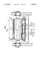
- FIG. 1 is a schematic front elevation view of an apparatus for compensating for cylinder sag in accordance with the present invention.
- FIG. 2 is a cross-sectional view of the apparatus taken along line II--II of FIG. 1.
- a forme cylinder generally at 1, which is intended for use in gravure printing, is supported by its axle journals 2 and 3 in bearings 4 and 5 which are received in side frames 7 and 8 of the machine frame.
- a pressure roller 9 is rotatably supported above the forme cylinder 1 on its axle journals 11 and 12 which are received in bearing bushings in vertically extending guide spindles. This pressure roller is capable of being thrown on the forme cylinder 1.
- a pressure roller and throw-on device of this general type is shown in German document No. DE 28 22 531 A.
- An ink trough, generally at 13, is situated beneath the gravure forme roller 1. As may be seen in FIG. 2, this ink trough 13 is supplied with ink 14 that is received by the gravure forme roller 1.
- An ink forme roller 19 is situated in the ink trough 13 by suitable supports as will be discussed in detail subsequently. This ink forme roller 19 is utilized to supply ink 14 from the ink trough 13 to a peripheral surface 6 of the gravure forme cylinder 1. While not specifically shown in the drawings, it will be understood that the ink trough 13 can be surrounded by an overflow trough which will receive ink 14 that flows out from the ink trough 13. This ink can be returned to the ink trough 13 by a suitable pump system which is also not shown.
- the ink 14 from the ink trough 13 is applied to the periphery 6 of the gravure forme roller 1 by the ink forme roller 19.
- a suitable doctor blade assembly 33, as seen in FIG. 2 is capable of being thrown-on to the forme cylinder 1.
- a paper web, generally at 34, is printed by the gravure forme cylinder 1 as it travels in the direction indicated by the arrow and is brought into contact with the gravure forme cylinder 1 by the pressure roller 9.
- a press-on or support roller 16 is situated in the ink trough 13 generally beneath the gravure forme cylinder 1.
- This press-on or support roller 16 is supported so that it can be thrown-on or brought into engagement with the peripheral surface 6 of the gravure forme roller 1 in a manner as will be discussed in more detail shortly.
- the forme cylinder 1 has a center of rotation 10 while the press-on or support roller 16 has a center of rotation 15.
- these centers of rotation 10 and 15 may be situated on a vertically extending line 18 so that the press-on roller 16 is directly beneath the gravure forme cylinder 1.
- the center of rotation 15 of the press-on or support roller 16 can be on a straight line 20 or 20.1 which originates at the center of rotation 10 of the gravure forme cylinder 1 and which may be positioned at an angle ⁇ in the range of 2° to 10° with respect to the vertical line 18.
- the angle + ⁇ refers to a direction of rotation of the forme cylinder 1 in the clockwise direction.
- the angle - ⁇ extends in the counterclockwise direction and corresponds to the positioning of the center of rotation 15 of the support or press-on roller 16 at a reversal of the direction of rotation of the forme cylinder 1.
- the circumferential curve length of the angle + ⁇ or - ⁇ on the periphery 6 of the gravure forme cylinder 1 corresponds at a maximum to no more than one half of the diameter of the support or press-on roller 16.
- the support roller 16 extends parallel to an axis of rotation of the gravure forme cylinder 1 and is symmetrical about a center vertical plane of symmetry 17.
- both the support roller 16 and the gravure forme cylinder 1 extend laterally an equal amount to both sides of the plane of symmetry 17.
- the support roller 16 has a length l which is less than a length l 1 of the gravure forme cylinder 1.
- the length l of the support roller 16 is preferably in the range of 0.1 to 0.6 times the length l 1 of the gravure forme cylinder 1.
- the support roller 16 may not be symmetrical about the plane of symmetry 17.
- the support roller 16 could be located asymmetrically to the plane of symmetry beneath the gravure forme cylinder 1. This could be accomplished in a manner not specifically depicted in the drawings by supporting the support roller in a dove-tail guide with a suitable locking device in the ink trough 13.
- the ink forme roller 19 is supported in the ink trough 13. As is shown most clearly in FIG. 2, the ink forme roller 19 is rotatably supported parallel to the support roller 16 but outside of the vertical line 18.
- the ink forme roller 19 has a length which is generally the same as the face length l 1 of the forme cylinder 1.
- Both the ink forme roller 19 and the support roller 16 have surface coatings.
- the coatings of the support roller consists of a material which is suitable for contact with the gravure forme cylinder 1 and for power transmission to, and support of the cylinder 1. This coating is preferably of a plastic material or rubber and has a hardness of more than 70 Shore A.
- the ink forme roller 19 is preferably not separately driven and has an absorbent coating, for example a coating made of sponge cloth for absorption of ink 14 out of the ink trough 13 and for transfer of the ink to the peripheral surface 6 of the gravure forme cylinder 1.
- an absorbent coating for example a coating made of sponge cloth for absorption of ink 14 out of the ink trough 13 and for transfer of the ink to the peripheral surface 6 of the gravure forme cylinder 1.
- the support roller 16 and the ink forme roller 19 are both supported in bearing brackets 22 and 23, and 24 and 25, respectively which are supported on a bottom surface 21 of the ink trough 13.
- compression springs 27 which are in the form of steel springs or in the form of hydraulic or pneumatic cylinders. These compression springs 27 act to continually urge their bearing brackets 22-25 and hence the support roller 16 and the ink forme roller 19 which are supported thereby into engagement with the surface 6 of the gravure forme cylinder 1.
- the compression springs 27 may be omitted between the bearing brackets 22-25 and the bottom surface 21 of the ink trough 13. This brings the bearing brackets 22 and 23 for the support roller 16 and the bearing brackets 24 and 25 for the ink forme roller 19 into direct contact with the inner bottom surface 21 of the ink trough 13. These bearing brackets 22-25 are thereby firmly connected to the surface 21.
- the ink trough 13 has a reinforcing plate 28 secured to its exterior bottom surface.
- a lifting device, generally at 32 is in engagement with this reinforcing plate 28 and is operable to elevate the entire ink trough 13, including the support roller 16 and the ink forme roller 19 toward the gravure forme cylinder 1.
- the lifting device, generally at 32 utilizes two spaced piston rods and cylinders 29 and 31 that engage the support plate 28 generally directly beneath the center of rotation 10 of the gravure forme cylinder 1.
- This lifting device 32 causes the ink trough 13 to move vertically along the vertical line 18, as seen most clearly in FIG. 2.
- the lifting device 32 is executed in accordance with the principle of hydraulic lifting platforms.
- the lifting device 32 could operate using only one of the piston rods 29 or 31.
- the sole piston rod would be situated at the plane of symmetry 17, assuming that the support roller 16 were also symmetrical about this plane.
- the lifting device 32 can also be driven by alternative hydraulic, mechanical or pneumatic means.
- a limit switch 26 is utilized to insure that the stroke of the lifting device 32 is limited so that the force exerted by the support roller 16 against the surface of the gravure forme cylinder 1 is within present limits.
- the press on or support roller 16 may be resiliently supported in the ink trough 13 through its bearing brackets 22 and 23 by a suitable pneumatic throw-on system. This allows the support roller 16 to be activated directly and only when needed.
- the support roller 16 can also be provided with its own separate drive motor which will be actuated in any generally well known manner.
Landscapes
- Engineering & Computer Science (AREA)
- Mechanical Engineering (AREA)
- Rotary Presses (AREA)
- Inking, Control Or Cleaning Of Printing Machines (AREA)
Applications Claiming Priority (2)
| Application Number | Priority Date | Filing Date | Title |
|---|---|---|---|
| DE4238054A DE4238054C2 (de) | 1992-11-11 | 1992-11-11 | Einrichtung zum Kompensieren der Durchbiegung eines Tiefdruckformzylinders |
| DE4238054.5 | 1992-11-11 |
Publications (1)
| Publication Number | Publication Date |
|---|---|
| US5454311A true US5454311A (en) | 1995-10-03 |
Family
ID=6472622
Family Applications (1)
| Application Number | Title | Priority Date | Filing Date |
|---|---|---|---|
| US08/149,787 Expired - Fee Related US5454311A (en) | 1992-11-11 | 1993-11-10 | Apparatus for compensating for cylinder sag |
Country Status (4)
| Country | Link |
|---|---|
| US (1) | US5454311A (de) |
| EP (1) | EP0598268B1 (de) |
| JP (1) | JP2726228B2 (de) |
| DE (2) | DE4238054C2 (de) |
Cited By (3)
| Publication number | Priority date | Publication date | Assignee | Title |
|---|---|---|---|---|
| US6374731B1 (en) * | 1997-04-18 | 2002-04-23 | Heidelberger Druckmaschinen Ag | Lithographic newspaper printing press |
| US6701838B2 (en) * | 2000-02-10 | 2004-03-09 | Fischem & Krecke Gmbh & Co. | Engraved transfer cylinder for a flexographic printing press |
| WO2005035249A1 (de) * | 2003-10-08 | 2005-04-21 | Koenig & Bauer Aktiengesellschaft | Tiefdruckwerk |
Families Citing this family (5)
| Publication number | Priority date | Publication date | Assignee | Title |
|---|---|---|---|---|
| DE19701226B4 (de) * | 1997-01-16 | 2004-10-07 | Heidelberger Druckmaschinen Ag | Druckwerk einer Offsetrotationsdruckmaschine |
| DE19911180C2 (de) | 1999-03-12 | 2001-02-01 | Koenig & Bauer Ag | Druckwerk für eine Rotationsdruckmaschine |
| CN103707636B (zh) * | 2013-12-18 | 2016-01-20 | 陕西北人印刷机械有限责任公司 | 一种凹版刷印机墨槽复位装置及其控制方法 |
| CN106274031B (zh) * | 2016-09-29 | 2018-07-27 | 安徽集友纸业包装有限公司 | 印刷载墨装置及凹版印刷装置 |
| CN112537117A (zh) * | 2020-12-10 | 2021-03-23 | 黄山枘淼机电科技有限公司 | 一种可调大幅半径双辊卷筒材料印刷设备 |
Citations (18)
| Publication number | Priority date | Publication date | Assignee | Title |
|---|---|---|---|---|
| US1890922A (en) * | 1929-04-13 | 1932-12-13 | Edward A Waller | Multicolor printing press |
| DE604870C (de) * | 1934-10-30 | Linotype Machinery Ltd | Farbwerk fuer Rotationstiefdruckmaschinen | |
| DE1087443B (de) * | 1958-02-10 | 1960-08-18 | Kuesters Eduard | Walzenpresse fuer die Druckbehandlung von Waren-, insbesondere Papierbahnen |
| US3429166A (en) * | 1965-03-09 | 1969-02-25 | Aluminium Lab Ltd | Rolling mill |
| DE1460785A1 (de) * | 1961-02-02 | 1969-03-27 | Oliveira Barros Almerindo Jami | Einrichtung zum Bedrucken oder Bemustern von Stoffen |
| US3793952A (en) * | 1972-07-25 | 1974-02-26 | Windmoeller & Hoelscher | Convertible printing mechanism for intaglio and flexographic printing |
| CA980624A (en) * | 1973-02-02 | 1975-12-30 | John C. Motter | Pressure roller device for a rotogravure printing press |
| US4132166A (en) * | 1977-10-07 | 1979-01-02 | Aldo Bugnone | Mounting for rotary cylinders, particularly in a printing press |
| DE2822531A1 (de) * | 1978-05-23 | 1979-11-29 | Frankenthal Ag Albert | Tiefdruckmaschine |
| DE2849202A1 (de) * | 1978-11-13 | 1980-05-14 | Frankenthal Ag Albert | Zylinder fuer eine druckmaschine |
| GB2054464A (en) * | 1979-07-05 | 1981-02-18 | Waertsilae Oy Ab | Printing press |
| GB2087797A (en) * | 1980-11-10 | 1982-06-03 | Dowling Simon Barrow | Improvements in printing presses |
| DE3218158A1 (de) * | 1982-05-14 | 1983-11-17 | Albert-Frankenthal Ag, 6710 Frankenthal | Zylinder fuer bahnfoermiges material verarbeitende maschinen |
| DE3710724A1 (de) * | 1986-11-07 | 1988-05-19 | Escher Wyss Ag | Presseur einer tiefdruckrotationsmaschine |
| US4827284A (en) * | 1986-12-08 | 1989-05-02 | Fuji Photo Film Co., Ltd. | Image recorder with a back-up roller pressing the nip roller into engagement |
| US4901641A (en) * | 1988-11-30 | 1990-02-20 | Bobst Sa | Printing press |
| EP0477768A1 (de) * | 1990-09-26 | 1992-04-01 | KOENIG & BAUER-ALBERT AKTIENGESELLSCHAFT | Farbwerk für eine Tiefdruckmaschine |
| US5188027A (en) * | 1989-06-30 | 1993-02-23 | Office Meccaniche G. Cerutti S.P.A. | Printing apparatus with quickly changeable printing plate |
Family Cites Families (6)
| Publication number | Priority date | Publication date | Assignee | Title |
|---|---|---|---|---|
| DE1883014U (de) * | 1963-09-12 | 1963-11-21 | Benteler Werke Ag | Druckwalze zur erzeugung eines gleichmaessigen andruckes entlang einer quetschfuge einer vorrichtung zur behandlung von warenbahnen. |
| JPS54156704A (en) * | 1978-05-30 | 1979-12-11 | Shiyougo Nagao | Relief printing plate and relief printing machine |
| JPS6368434U (de) * | 1986-10-24 | 1988-05-09 | ||
| JPH01158131U (de) * | 1988-04-25 | 1989-11-01 | ||
| JPH0471250U (de) * | 1990-11-05 | 1992-06-24 | ||
| JP3031547U (ja) * | 1996-05-09 | 1996-11-29 | 株式会社東京セロレーベル | オーバーヘッドプロジェクタ用支持シート |
-
1992
- 1992-11-11 DE DE4238054A patent/DE4238054C2/de not_active Expired - Fee Related
-
1993
- 1993-10-30 EP EP93117647A patent/EP0598268B1/de not_active Expired - Lifetime
- 1993-10-30 DE DE59306258T patent/DE59306258D1/de not_active Expired - Fee Related
- 1993-11-10 US US08/149,787 patent/US5454311A/en not_active Expired - Fee Related
- 1993-11-10 JP JP5280978A patent/JP2726228B2/ja not_active Expired - Lifetime
Patent Citations (19)
| Publication number | Priority date | Publication date | Assignee | Title |
|---|---|---|---|---|
| DE604870C (de) * | 1934-10-30 | Linotype Machinery Ltd | Farbwerk fuer Rotationstiefdruckmaschinen | |
| US1890922A (en) * | 1929-04-13 | 1932-12-13 | Edward A Waller | Multicolor printing press |
| DE1087443B (de) * | 1958-02-10 | 1960-08-18 | Kuesters Eduard | Walzenpresse fuer die Druckbehandlung von Waren-, insbesondere Papierbahnen |
| DE1460785A1 (de) * | 1961-02-02 | 1969-03-27 | Oliveira Barros Almerindo Jami | Einrichtung zum Bedrucken oder Bemustern von Stoffen |
| US3429166A (en) * | 1965-03-09 | 1969-02-25 | Aluminium Lab Ltd | Rolling mill |
| US3793952A (en) * | 1972-07-25 | 1974-02-26 | Windmoeller & Hoelscher | Convertible printing mechanism for intaglio and flexographic printing |
| CA980624A (en) * | 1973-02-02 | 1975-12-30 | John C. Motter | Pressure roller device for a rotogravure printing press |
| US4132166A (en) * | 1977-10-07 | 1979-01-02 | Aldo Bugnone | Mounting for rotary cylinders, particularly in a printing press |
| DE2822531A1 (de) * | 1978-05-23 | 1979-11-29 | Frankenthal Ag Albert | Tiefdruckmaschine |
| DE2849202A1 (de) * | 1978-11-13 | 1980-05-14 | Frankenthal Ag Albert | Zylinder fuer eine druckmaschine |
| GB2054464A (en) * | 1979-07-05 | 1981-02-18 | Waertsilae Oy Ab | Printing press |
| GB2087797A (en) * | 1980-11-10 | 1982-06-03 | Dowling Simon Barrow | Improvements in printing presses |
| DE3218158A1 (de) * | 1982-05-14 | 1983-11-17 | Albert-Frankenthal Ag, 6710 Frankenthal | Zylinder fuer bahnfoermiges material verarbeitende maschinen |
| DE3710724A1 (de) * | 1986-11-07 | 1988-05-19 | Escher Wyss Ag | Presseur einer tiefdruckrotationsmaschine |
| US4827284A (en) * | 1986-12-08 | 1989-05-02 | Fuji Photo Film Co., Ltd. | Image recorder with a back-up roller pressing the nip roller into engagement |
| US4901641A (en) * | 1988-11-30 | 1990-02-20 | Bobst Sa | Printing press |
| US5188027A (en) * | 1989-06-30 | 1993-02-23 | Office Meccaniche G. Cerutti S.P.A. | Printing apparatus with quickly changeable printing plate |
| EP0477768A1 (de) * | 1990-09-26 | 1992-04-01 | KOENIG & BAUER-ALBERT AKTIENGESELLSCHAFT | Farbwerk für eine Tiefdruckmaschine |
| US5103723A (en) * | 1990-09-26 | 1992-04-14 | Albert-Frankenthal Aktiengesellschaft | Inking unit for gravure printing press |
Cited By (6)
| Publication number | Priority date | Publication date | Assignee | Title |
|---|---|---|---|---|
| US6374731B1 (en) * | 1997-04-18 | 2002-04-23 | Heidelberger Druckmaschinen Ag | Lithographic newspaper printing press |
| US6701838B2 (en) * | 2000-02-10 | 2004-03-09 | Fischem & Krecke Gmbh & Co. | Engraved transfer cylinder for a flexographic printing press |
| WO2005035249A1 (de) * | 2003-10-08 | 2005-04-21 | Koenig & Bauer Aktiengesellschaft | Tiefdruckwerk |
| US20070051256A1 (en) * | 2003-10-08 | 2007-03-08 | Riedel Uwe J | Rotogravure printing units |
| CN100460207C (zh) * | 2003-10-08 | 2009-02-11 | 赛鲁迪公司 | 凹版印刷装置 |
| US7493856B2 (en) | 2003-10-08 | 2009-02-24 | Officine Meccaniche Giovanni Cerutti S.P.A. | Rotogravure printing units |
Also Published As
| Publication number | Publication date |
|---|---|
| EP0598268A1 (de) | 1994-05-25 |
| DE59306258D1 (de) | 1997-05-28 |
| JPH06198839A (ja) | 1994-07-19 |
| DE4238054A1 (de) | 1994-05-19 |
| JP2726228B2 (ja) | 1998-03-11 |
| DE4238054C2 (de) | 1996-07-11 |
| EP0598268B1 (de) | 1997-04-23 |
Similar Documents
| Publication | Publication Date | Title |
|---|---|---|
| US3828672A (en) | Apparatus for fitting flexible printing plates and rigging to printing press cylinders | |
| US4149461A (en) | Device for eliminating effect of bearing play in printing press cylinders | |
| FI72684C (fi) | Tryckanordning foer sammeltryck-rotationsmaskin foer tryckning av vaerdepapper. | |
| US6782816B1 (en) | Printing unit of a rotary printing press | |
| US5454311A (en) | Apparatus for compensating for cylinder sag | |
| US4397235A (en) | Multi-printing mode rotary printing machine | |
| US5320038A (en) | Method and apparatus for adjusting printing unit cylinders | |
| US5333545A (en) | Sheet-fed rotary offset printing press with a removable imprinting or finishing unit | |
| US6886461B2 (en) | Short inking system for a rotary printing machine | |
| US5718171A (en) | Process and rotary printing machine for indirect rotogravure printing | |
| US6220156B1 (en) | Multi-color central impression printing device having selectively raised and lowered printing units | |
| US9669614B2 (en) | Printing unit | |
| US1855525A (en) | Web-fed gravure press | |
| US4250809A (en) | Perfecting or multicolor offset printing press | |
| CN114953710B (zh) | 一种柔版印刷机 | |
| DE59003110D1 (de) | Antriebsmechanismus an Offsetdruckmaschinen zum axialen Hin- und Herbewegen der ersten oder der ersten und zweiten Walze eines umstellbaren Walzenpaares. | |
| GB2221652A (en) | Rotary printing press cylinder | |
| US7493856B2 (en) | Rotogravure printing units | |
| DE3364596D1 (en) | Means for preventing stripes on printing press rollers | |
| JPH08300605A (ja) | 着けローラを支承する装置 | |
| US20070272104A1 (en) | Coating device | |
| ES244550U (es) | Perfeccionamientos introducidos en una impresora offset. | |
| JPH0775883B2 (ja) | 枚葉紙印刷機の枚葉紙案内ドラムへの枚葉紙案内 | |
| WO2019048088A1 (de) | Changierbare walze sowie druckmaschine mit mehreren druckwerken mit einer derartigen walze | |
| CN218505490U (zh) | 一种防伪标签印刷用纸张固定装置 |
Legal Events
| Date | Code | Title | Description |
|---|---|---|---|
| AS | Assignment |
Owner name: ALBERT FRANKENTHAL AKTIENGESELLSCHAFT, GERMANY Free format text: ASSIGNMENT OF ASSIGNORS INTEREST;ASSIGNOR:REFFERT, ROLAND;REEL/FRAME:006762/0347 Effective date: 19931031 |
|
| FEPP | Fee payment procedure |
Free format text: PAYOR NUMBER ASSIGNED (ORIGINAL EVENT CODE: ASPN); ENTITY STATUS OF PATENT OWNER: LARGE ENTITY |
|
| FPAY | Fee payment |
Year of fee payment: 4 |
|
| REMI | Maintenance fee reminder mailed | ||
| LAPS | Lapse for failure to pay maintenance fees | ||
| STCH | Information on status: patent discontinuation |
Free format text: PATENT EXPIRED DUE TO NONPAYMENT OF MAINTENANCE FEES UNDER 37 CFR 1.362 |
|
| FP | Lapsed due to failure to pay maintenance fee |
Effective date: 20031003 |