US5367576A - Horn speaker - Google Patents
Horn speaker Download PDFInfo
- Publication number
- US5367576A US5367576A US07/942,823 US94282392A US5367576A US 5367576 A US5367576 A US 5367576A US 94282392 A US94282392 A US 94282392A US 5367576 A US5367576 A US 5367576A
- Authority
- US
- United States
- Prior art keywords
- horn
- cabinet
- speaker
- front plate
- speaker body
- Prior art date
- Legal status (The legal status is an assumption and is not a legal conclusion. Google has not performed a legal analysis and makes no representation as to the accuracy of the status listed.)
- Expired - Lifetime
Links
- 238000000034 method Methods 0.000 claims abstract description 5
- 238000010276 construction Methods 0.000 abstract description 2
- 238000009434 installation Methods 0.000 abstract description 2
- 238000004519 manufacturing process Methods 0.000 description 2
- 239000000853 adhesive Substances 0.000 description 1
- 230000001070 adhesive effect Effects 0.000 description 1
- 239000007795 chemical reaction product Substances 0.000 description 1
- 238000012986 modification Methods 0.000 description 1
- 230000004048 modification Effects 0.000 description 1
- 239000000047 product Substances 0.000 description 1
- 238000003466 welding Methods 0.000 description 1
Images

Classifications
-
- H—ELECTRICITY
- H04—ELECTRIC COMMUNICATION TECHNIQUE
- H04R—LOUDSPEAKERS, MICROPHONES, GRAMOPHONE PICK-UPS OR LIKE ACOUSTIC ELECTROMECHANICAL TRANSDUCERS; DEAF-AID SETS; PUBLIC ADDRESS SYSTEMS
- H04R1/00—Details of transducers, loudspeakers or microphones
- H04R1/02—Casings; Cabinets ; Supports therefor; Mountings therein
-
- H—ELECTRICITY
- H04—ELECTRIC COMMUNICATION TECHNIQUE
- H04R—LOUDSPEAKERS, MICROPHONES, GRAMOPHONE PICK-UPS OR LIKE ACOUSTIC ELECTROMECHANICAL TRANSDUCERS; DEAF-AID SETS; PUBLIC ADDRESS SYSTEMS
- H04R1/00—Details of transducers, loudspeakers or microphones
- H04R1/20—Arrangements for obtaining desired frequency or directional characteristics
- H04R1/22—Arrangements for obtaining desired frequency or directional characteristics for obtaining desired frequency characteristic only
- H04R1/30—Combinations of transducers with horns, e.g. with mechanical matching means, i.e. front-loaded horns
-
- H—ELECTRICITY
- H04—ELECTRIC COMMUNICATION TECHNIQUE
- H04R—LOUDSPEAKERS, MICROPHONES, GRAMOPHONE PICK-UPS OR LIKE ACOUSTIC ELECTROMECHANICAL TRANSDUCERS; DEAF-AID SETS; PUBLIC ADDRESS SYSTEMS
- H04R1/00—Details of transducers, loudspeakers or microphones
- H04R1/20—Arrangements for obtaining desired frequency or directional characteristics
- H04R1/22—Arrangements for obtaining desired frequency or directional characteristics for obtaining desired frequency characteristic only
- H04R1/28—Transducer mountings or enclosures modified by provision of mechanical or acoustic impedances, e.g. resonator, damping means
Definitions
- the present invention relates to a horn speaker formed of a speaker body housed in a cabinet and a horn disposed on a front plate of the cabinet and more particularly to a novel and highly effective horn speaker that can be assembled more easily and less expensively than conventional horn speakers.
- a conventional horn speaker typically includes a cabinet, a speaker body mounted in the cabinet, and a horn projecting forward from the speaker and cabinet and fixed to a front plate of the cabinet.
- An object of the present invention is to solve the problems of the prior art described above and in particular to provide a horn speaker wherein the restrictions as to the shape of the speaker body, the size and shape of the horn, etc., are relaxed, so that it is easier to obtain the shapes required for these items by design considerations.
- a horn speaker comprising a cabinet, a speaker body mounted in the cabinet, a horn including at least one horn piece, and attachment means; wherein the attachment means detachably attaches the cabinet, speaker body and horn piece together in such a manner that the horn piece overhangs at least a portion of the speaker body and the cabinet.
- a horn speaker comprising: a cabinet; a speaker body housed in the cabinet, the cabinet having a front plate formed with an open portion and the speaker body being fixed to the front plate at the open portion; and a horn piece disposed on an outer face of the front plate; the horn speaker being characterized in that the speaker body and the horn piece are integrally fastened to the front plate, at least the horn piece being detachable from the front plate.
- a method of assembling a horn speaker comprising the steps of: disposing a speaker body within a cabinet; disposing a horn piece to one side of the speaker body so that it overhangs at least a portion of the speaker body and cabinet; and applying detachable fastening means to the cabinet, speaker body and horn piece to fasten the cabinet, speaker body and horn piece detachably together.
- a horn speaker constructed in accordance with the invention thus has a cabinet, a speaker body housed in the cabinet and fixed to a front plate of the cabinet at an open portion formed therein, and a horn disposed on the outer face of the front plate of the cabinet.
- the horn has at least one member or horn piece that is detachable from the front plate of the cabinet, and the speaker body and the horn are integrally fastened to the front plate.
- the horn has two separate horn pieces, and the two horn pieces are respectively detachably attached to the front plate of the cabinet at locations on opposite sides of the open portion.
- the speaker body is placed into the cabinet from the front of the cabinet rather than from the rear and fixed to the front plate of the cabinet together with the horn. Therefore, restrictions on the design of the speaker body and horn are relaxed.
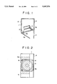
- FIG. 1 is a section view taken in a plane parallel to a speaker axis and perpendicular to the planes in which its horn pieces lie, showing a first preferred embodiment of a horn speaker constructed in accordance with the present invention
- FIG. 2 is a front view of the apparatus of FIG. 1;
- FIG. 3 is an enlarged sectional view of a key portion of the structure shown in FIG. 1;
- FIG. 4 is a sectional view corresponding to FIG. 1 but showing a second preferred embodiment of a horn speaker constructed in accordance with the present invention.
- FIGS. 1 to 3 who a first preferred embodiment of the present invention.
- FIGS. 1 and 2 show a cabinet 1 in the form of a box.
- the cabinet 1 can have a variety of shapes, for example, substantially the shape of a rectangular parallelpiped, as illustrated.
- the cabinet 1 has a front plate 1a formed with an open portion 2 having substantially the space of a square.
- One horn piece 4 is parallel to (coplanar with) the side wall 1r, to which it is permanently or detachably attached by adhesive, sonic welding, a separate screw plate, or in any other suitable way, and the other horn piece 5, which is connected to the sidewall 1l, slants so as to partly cover or overhang the front plate 1a, opening portion 2, and speaker body 3.
- the rear of the horn thus has a larger opening than the front.
- a part 5a of the horn piece 5 overhanging the speaker body 3 is arranged to be detachable.
- the horn piece 5 does not imply that the horn piece 5 physically touches the speaker cone or that it is suspended or attached at a position above the speaker cone. Rather, as seen from the front of the cabinet 1 or speaker body 3, the horn piece 5 extends from a position on one side of the speaker body 3 (e.g., the left side, the right side, the top side, the bottom side, etc.) to a position in front of the cabinet 1 and speaker body 3; i.e., to a position between the observer on the one hand and the cabinet 1 and speaker body 3 on the other.
- one side of the speaker body 3 e.g., the left side, the right side, the top side, the bottom side, etc.
- the dimensions of the horn piece 5 and the dihedral angle formed by the plane of the horn piece 5 and the plane of the front plate 1a, etc., are not critical so far as the present invention is concerned and can be selected by the manufacturer in accordance with space and acoustic design considerations.
- the horn piece 5 need not even be planar and can be curved in accordance with acoustic and design considerations.
- the present invention covers not those features but rather the manner in which the cabinet 1, speaker body 3, and horn piece 5 are assembled.
- the speaker body 3 is inserted in the interior of the cabinet 1 through the opening portion 2, and four corners of a flange 3a at the front of the speaker body 3 are fixed to the cabinet 1 with respective bolts 6.
- the part 5a of the horn 5 is provided with two leg portions 5b disposed near its edge that abuts the cabinet 1.
- One leg portion 5b is near the top and the other near the bottom of the part 5a, and both leg portions project towards the cabinet 1. Since the leg portions 5b are aligned vertically with each other, only one leg portion 5b is visible in FIG. 1.
- FIG. 3 best illustrates the construction of the leg portions 5b.
- the leg portion 5b, the front plate 1a of the cabinet 1, and the flange portion 3a of the speaker body 3, which is sandwiched between the leg portion 5b and the front plate 1a, are adapted to be fastened together with a single one of the bolts 6 at each of the two locations where the part 5a is attached to the cabinet.
- the speaker body 3 since the portion 5a of the horn 5 overhanging the speaker body 3 is detachable, the speaker body 3 can easily be inserted into the cabinet 1 through the opening portion 2 formed in the front plate 1a of the cabinet 1 while the portion 5a detached. Thereafter, the flange portion 3a of the speaker body 3 and the portion 5a of the horn piece 5 can be integrally fastened to the cabinet 1 with the bolts 6. Therefore, restrictions as to the shape of the horn piece 5, the shape, size and method of attachment of the speaker body 3, etc., can be relaxed, and it becomes easier to obtain the shape required by acoustic, mechanical, and aesthetic design considerations. As a result, fabrication becomes easier, productivity is increased, and a better end product results.
- a portion 5a of the horn piece 5 is arranged to be detachable is described above, it is also within the scope of the invention to make the entirety of the horn piece 5 detachable.
- a pair of horn pieces 5 and 5' may be arranged to slant forwardly and inwardly as shown in FIG. 4, and both of the horn pieces 5 and 5' may be detachable.
- the horn pieces 5 and 5' in the embodiment of FIG. 4 are preferably mirror images of each other. In the embodiment of the invention illustrated in FIG. 4, the installation of the speaker body 3 in the cabinet 1 becomes still easier.
- the two horn pieces may form the same or different angles with respect to the front plate and may form the same or different angles with respect to the sidewalls of the cabinet.
Landscapes
- Physics & Mathematics (AREA)
- Engineering & Computer Science (AREA)
- Acoustics & Sound (AREA)
- Signal Processing (AREA)
- Health & Medical Sciences (AREA)
- Otolaryngology (AREA)
- Obtaining Desirable Characteristics In Audible-Bandwidth Transducers (AREA)
- Details Of Audible-Bandwidth Transducers (AREA)
Applications Claiming Priority (2)
| Application Number | Priority Date | Filing Date | Title |
|---|---|---|---|
| JP25843591A JP3209350B2 (ja) | 1991-09-10 | 1991-09-10 | ホーンスピーカ |
| JP3-258435 | 1991-09-10 |
Publications (1)
| Publication Number | Publication Date |
|---|---|
| US5367576A true US5367576A (en) | 1994-11-22 |
Family
ID=17320169
Family Applications (1)
| Application Number | Title | Priority Date | Filing Date |
|---|---|---|---|
| US07/942,823 Expired - Lifetime US5367576A (en) | 1991-09-10 | 1992-09-10 | Horn speaker |
Country Status (6)
| Country | Link |
|---|---|
| US (1) | US5367576A (de) |
| EP (1) | EP0532321B1 (de) |
| JP (1) | JP3209350B2 (de) |
| KR (1) | KR100255344B1 (de) |
| DE (1) | DE69211458T2 (de) |
| ES (1) | ES2089412T3 (de) |
Cited By (3)
| Publication number | Priority date | Publication date | Assignee | Title |
|---|---|---|---|---|
| US20040003962A1 (en) * | 2002-07-03 | 2004-01-08 | Christopher Gardner | Planar acoustic waveguide |
| US20090279733A1 (en) * | 2008-05-09 | 2009-11-12 | Michael Schuster | Speaker assembly arrangement for a vehicle and method of mounting a speaker |
| US9591399B1 (en) * | 2015-08-14 | 2017-03-07 | Unity Opto Technology Co., Ltd. | Automatically controlled directional speaker, and lamp thereof |
Families Citing this family (1)
| Publication number | Priority date | Publication date | Assignee | Title |
|---|---|---|---|---|
| CN113132580B (zh) * | 2019-12-31 | 2023-06-09 | 杭州海康威视数字技术股份有限公司 | 摄像机 |
Citations (13)
| Publication number | Priority date | Publication date | Assignee | Title |
|---|---|---|---|---|
| US2102212A (en) * | 1935-09-30 | 1937-12-14 | Rca Corp | Sound reproducing apparatus |
| US2541980A (en) * | 1947-12-03 | 1951-02-20 | Antone Alfred William | Miniature loud-speaker attachment for hair driers |
| DE890810C (de) * | 1943-11-03 | 1953-09-21 | Lorenz C Ag | Schutzeinrichtung fuer Lautsprecher-Chassis gegen Schuss-Schall-Einwirkungen |
| US2853146A (en) * | 1955-02-07 | 1958-09-23 | George A Coates | Transmitter with vibratile air coupling |
| US3136382A (en) * | 1962-02-14 | 1964-06-09 | Thaler Edward | Acoustic transducer |
| US3432002A (en) * | 1967-05-01 | 1969-03-11 | Ltv Ling Altec Inc | Horn-loaded loudspeaker |
| US3435910A (en) * | 1967-11-22 | 1969-04-01 | Uolevi L Lahti | Semispherical loudspeaker |
| US3536158A (en) * | 1967-05-01 | 1970-10-27 | Ltv Ling Altec Inc | Explosion-proof,horn-loaded loudspeaker |
| US3982607A (en) * | 1975-01-28 | 1976-09-28 | Evans Arnold D | Loudspeaker cabinet having an integrally constructed horn |
| US4082159A (en) * | 1976-05-24 | 1978-04-04 | Mar-Kel Lighting, Inc. | Ceramic speaker enclosure |
| US4225010A (en) * | 1979-04-18 | 1980-09-30 | Arthur P. Bagby | Loudspeaker system |
| US4378471A (en) * | 1981-02-18 | 1983-03-29 | Ibuki Kogyo Co., Ltd. | Horn speaker with linear grooves in a front surface of a pole piece of a yoke |
| US5109423A (en) * | 1988-06-30 | 1992-04-28 | Jacobson Larry L | Audio system with amplifier and signal device |
-
1991
- 1991-09-10 JP JP25843591A patent/JP3209350B2/ja not_active Expired - Fee Related
-
1992
- 1992-08-25 KR KR1019920015327A patent/KR100255344B1/ko not_active IP Right Cessation
- 1992-09-10 EP EP92308238A patent/EP0532321B1/de not_active Expired - Lifetime
- 1992-09-10 DE DE69211458T patent/DE69211458T2/de not_active Expired - Fee Related
- 1992-09-10 US US07/942,823 patent/US5367576A/en not_active Expired - Lifetime
- 1992-09-10 ES ES92308238T patent/ES2089412T3/es not_active Expired - Lifetime
Patent Citations (13)
| Publication number | Priority date | Publication date | Assignee | Title |
|---|---|---|---|---|
| US2102212A (en) * | 1935-09-30 | 1937-12-14 | Rca Corp | Sound reproducing apparatus |
| DE890810C (de) * | 1943-11-03 | 1953-09-21 | Lorenz C Ag | Schutzeinrichtung fuer Lautsprecher-Chassis gegen Schuss-Schall-Einwirkungen |
| US2541980A (en) * | 1947-12-03 | 1951-02-20 | Antone Alfred William | Miniature loud-speaker attachment for hair driers |
| US2853146A (en) * | 1955-02-07 | 1958-09-23 | George A Coates | Transmitter with vibratile air coupling |
| US3136382A (en) * | 1962-02-14 | 1964-06-09 | Thaler Edward | Acoustic transducer |
| US3536158A (en) * | 1967-05-01 | 1970-10-27 | Ltv Ling Altec Inc | Explosion-proof,horn-loaded loudspeaker |
| US3432002A (en) * | 1967-05-01 | 1969-03-11 | Ltv Ling Altec Inc | Horn-loaded loudspeaker |
| US3435910A (en) * | 1967-11-22 | 1969-04-01 | Uolevi L Lahti | Semispherical loudspeaker |
| US3982607A (en) * | 1975-01-28 | 1976-09-28 | Evans Arnold D | Loudspeaker cabinet having an integrally constructed horn |
| US4082159A (en) * | 1976-05-24 | 1978-04-04 | Mar-Kel Lighting, Inc. | Ceramic speaker enclosure |
| US4225010A (en) * | 1979-04-18 | 1980-09-30 | Arthur P. Bagby | Loudspeaker system |
| US4378471A (en) * | 1981-02-18 | 1983-03-29 | Ibuki Kogyo Co., Ltd. | Horn speaker with linear grooves in a front surface of a pole piece of a yoke |
| US5109423A (en) * | 1988-06-30 | 1992-04-28 | Jacobson Larry L | Audio system with amplifier and signal device |
Cited By (5)
| Publication number | Priority date | Publication date | Assignee | Title |
|---|---|---|---|---|
| US20040003962A1 (en) * | 2002-07-03 | 2004-01-08 | Christopher Gardner | Planar acoustic waveguide |
| US6860363B2 (en) * | 2002-07-03 | 2005-03-01 | Christopher Gardner | Planar acoustic waveguide |
| US20090279733A1 (en) * | 2008-05-09 | 2009-11-12 | Michael Schuster | Speaker assembly arrangement for a vehicle and method of mounting a speaker |
| US8139783B2 (en) * | 2008-05-09 | 2012-03-20 | Harman Becker Automotive Systems Gmbh | Speaker assembly arrangement for a vehicle and method of mounting a speaker |
| US9591399B1 (en) * | 2015-08-14 | 2017-03-07 | Unity Opto Technology Co., Ltd. | Automatically controlled directional speaker, and lamp thereof |
Also Published As
| Publication number | Publication date |
|---|---|
| DE69211458D1 (de) | 1996-07-18 |
| KR100255344B1 (ko) | 2000-05-01 |
| DE69211458T2 (de) | 1996-11-28 |
| JPH0576092A (ja) | 1993-03-26 |
| KR930007300A (ko) | 1993-04-22 |
| EP0532321A2 (de) | 1993-03-17 |
| JP3209350B2 (ja) | 2001-09-17 |
| ES2089412T3 (es) | 1996-10-01 |
| EP0532321B1 (de) | 1996-06-12 |
| EP0532321A3 (en) | 1993-11-18 |
Similar Documents
| Publication | Publication Date | Title |
|---|---|---|
| US5041698A (en) | Cover plate assembly for wall-mounted electrical wiring devices | |
| US5689574A (en) | Integral sound module for a modular monitor | |
| US5363150A (en) | Casing for a television set | |
| KR100231094B1 (ko) | 텔레비전 세트의 스피커 시스템 | |
| US6536855B2 (en) | Front cabinet and television set | |
| US5367576A (en) | Horn speaker | |
| US4847907A (en) | Speaker system for radiating acoustic energy into a cabin of a motor vehicle | |
| US5796443A (en) | Rear projection television utilizing two separate housings for easy transportation | |
| US20030066832A1 (en) | Enclosure having an extension member | |
| US4199204A (en) | Housing for a two-way radio or the like | |
| JP3583966B2 (ja) | テレビジョン受像機 | |
| JPH08125426A (ja) | アンテナユニット | |
| KR100463728B1 (ko) | 평판디스플레이장치의 영상판넬체결장치 | |
| JPH083136Y2 (ja) | 取付装置 | |
| WO2018159174A1 (ja) | 表示装置及びテレビジョン受信機 | |
| JPS5915110Y2 (ja) | 可撓性板状物の取付構造 | |
| JPH04241396A (ja) | 電子楽器のバスレフ形スピーカボックス | |
| JPH02136013A (ja) | 配線器具用化粧枠 | |
| JP3087218B2 (ja) | カーテンウオール | |
| KR100572978B1 (ko) | 연결구 및 이것을 이용한 패널의 연결 구조 | |
| JPH04292233A (ja) | 据置型ボックススピーカ | |
| JP2725517B2 (ja) | 電子部品の取付け構造 | |
| JPH08255473A (ja) | ディスクドライブ装置の取付構造 | |
| KR920006192Y1 (ko) | 환기팬 | |
| JPH0713370Y2 (ja) | モザイクパネル用化粧枠 |
Legal Events
| Date | Code | Title | Description |
|---|---|---|---|
| STCF | Information on status: patent grant |
Free format text: PATENTED CASE |
|
| FPAY | Fee payment |
Year of fee payment: 4 |
|
| FEPP | Fee payment procedure |
Free format text: PAYOR NUMBER ASSIGNED (ORIGINAL EVENT CODE: ASPN); ENTITY STATUS OF PATENT OWNER: LARGE ENTITY |
|
| FPAY | Fee payment |
Year of fee payment: 8 |
|
| REMI | Maintenance fee reminder mailed | ||
| FPAY | Fee payment |
Year of fee payment: 12 |