US5167528A - Method of manufacturing an electrical connector - Google Patents
Method of manufacturing an electrical connector Download PDFInfo
- Publication number
- US5167528A US5167528A US07/685,656 US68565691A US5167528A US 5167528 A US5167528 A US 5167528A US 68565691 A US68565691 A US 68565691A US 5167528 A US5167528 A US 5167528A
- Authority
- US
- United States
- Prior art keywords
- contactors
- housings
- free end
- base
- connector
- Prior art date
- Legal status (The legal status is an assumption and is not a legal conclusion. Google has not performed a legal analysis and makes no representation as to the accuracy of the status listed.)
- Expired - Lifetime
Links
- 238000004519 manufacturing process Methods 0.000 title claims description 8
- 230000009471 action Effects 0.000 claims abstract description 9
- 229910052751 metal Inorganic materials 0.000 claims description 18
- 239000002184 metal Substances 0.000 claims description 18
- 238000000034 method Methods 0.000 claims description 6
- 229920003002 synthetic resin Polymers 0.000 claims description 6
- 239000000057 synthetic resin Substances 0.000 claims description 6
- 238000005452 bending Methods 0.000 claims description 5
- 239000000758 substrate Substances 0.000 description 11
- 238000003491 array Methods 0.000 description 9
- 230000006870 function Effects 0.000 description 5
- 239000000470 constituent Substances 0.000 description 4
- 238000000465 moulding Methods 0.000 description 4
- 239000004020 conductor Substances 0.000 description 2
- 239000007769 metal material Substances 0.000 description 2
- 238000005192 partition Methods 0.000 description 2
- 230000008569 process Effects 0.000 description 2
- 230000002787 reinforcement Effects 0.000 description 2
- 229910000881 Cu alloy Inorganic materials 0.000 description 1
- 230000004075 alteration Effects 0.000 description 1
- 230000015572 biosynthetic process Effects 0.000 description 1
- 238000004140 cleaning Methods 0.000 description 1
- 230000001627 detrimental effect Effects 0.000 description 1
- 238000010586 diagram Methods 0.000 description 1
- PCHJSUWPFVWCPO-UHFFFAOYSA-N gold Chemical compound [Au] PCHJSUWPFVWCPO-UHFFFAOYSA-N 0.000 description 1
- 239000010931 gold Substances 0.000 description 1
- 229910052737 gold Inorganic materials 0.000 description 1
- 230000001771 impaired effect Effects 0.000 description 1
- 230000000977 initiatory effect Effects 0.000 description 1
- 239000007788 liquid Substances 0.000 description 1
- 239000000463 material Substances 0.000 description 1
- 230000004048 modification Effects 0.000 description 1
- 238000012986 modification Methods 0.000 description 1
- 229910000510 noble metal Inorganic materials 0.000 description 1
- 238000007747 plating Methods 0.000 description 1
- 238000009877 rendering Methods 0.000 description 1
- 230000015541 sensory perception of touch Effects 0.000 description 1
- 230000035939 shock Effects 0.000 description 1
- 229910000679 solder Inorganic materials 0.000 description 1
- 238000005476 soldering Methods 0.000 description 1
Images


Classifications
-
- H—ELECTRICITY
- H01—ELECTRIC ELEMENTS
- H01R—ELECTRICALLY-CONDUCTIVE CONNECTIONS; STRUCTURAL ASSOCIATIONS OF A PLURALITY OF MUTUALLY-INSULATED ELECTRICAL CONNECTING ELEMENTS; COUPLING DEVICES; CURRENT COLLECTORS
- H01R9/00—Structural associations of a plurality of mutually-insulated electrical connecting elements, e.g. terminal strips or terminal blocks; Terminals or binding posts mounted upon a base or in a case; Bases therefor
-
- H—ELECTRICITY
- H01—ELECTRIC ELEMENTS
- H01R—ELECTRICALLY-CONDUCTIVE CONNECTIONS; STRUCTURAL ASSOCIATIONS OF A PLURALITY OF MUTUALLY-INSULATED ELECTRICAL CONNECTING ELEMENTS; COUPLING DEVICES; CURRENT COLLECTORS
- H01R43/00—Apparatus or processes specially adapted for manufacturing, assembling, maintaining, or repairing of line connectors or current collectors or for joining electric conductors
- H01R43/20—Apparatus or processes specially adapted for manufacturing, assembling, maintaining, or repairing of line connectors or current collectors or for joining electric conductors for assembling or disassembling contact members with insulating base, case or sleeve
- H01R43/24—Assembling by moulding on contact members
-
- H—ELECTRICITY
- H01—ELECTRIC ELEMENTS
- H01R—ELECTRICALLY-CONDUCTIVE CONNECTIONS; STRUCTURAL ASSOCIATIONS OF A PLURALITY OF MUTUALLY-INSULATED ELECTRICAL CONNECTING ELEMENTS; COUPLING DEVICES; CURRENT COLLECTORS
- H01R12/00—Structural associations of a plurality of mutually-insulated electrical connecting elements, specially adapted for printed circuits, e.g. printed circuit boards [PCB], flat or ribbon cables, or like generally planar structures, e.g. terminal strips, terminal blocks; Coupling devices specially adapted for printed circuits, flat or ribbon cables, or like generally planar structures; Terminals specially adapted for contact with, or insertion into, printed circuits, flat or ribbon cables, or like generally planar structures
- H01R12/70—Coupling devices
- H01R12/71—Coupling devices for rigid printing circuits or like structures
- H01R12/712—Coupling devices for rigid printing circuits or like structures co-operating with the surface of the printed circuit or with a coupling device exclusively provided on the surface of the printed circuit
- H01R12/716—Coupling device provided on the PCB
-
- H—ELECTRICITY
- H01—ELECTRIC ELEMENTS
- H01R—ELECTRICALLY-CONDUCTIVE CONNECTIONS; STRUCTURAL ASSOCIATIONS OF A PLURALITY OF MUTUALLY-INSULATED ELECTRICAL CONNECTING ELEMENTS; COUPLING DEVICES; CURRENT COLLECTORS
- H01R12/00—Structural associations of a plurality of mutually-insulated electrical connecting elements, specially adapted for printed circuits, e.g. printed circuit boards [PCB], flat or ribbon cables, or like generally planar structures, e.g. terminal strips, terminal blocks; Coupling devices specially adapted for printed circuits, flat or ribbon cables, or like generally planar structures; Terminals specially adapted for contact with, or insertion into, printed circuits, flat or ribbon cables, or like generally planar structures
- H01R12/70—Coupling devices
- H01R12/71—Coupling devices for rigid printing circuits or like structures
- H01R12/72—Coupling devices for rigid printing circuits or like structures coupling with the edge of the rigid printed circuits or like structures
- H01R12/73—Coupling devices for rigid printing circuits or like structures coupling with the edge of the rigid printed circuits or like structures connecting to other rigid printed circuits or like structures
-
- H—ELECTRICITY
- H01—ELECTRIC ELEMENTS
- H01R—ELECTRICALLY-CONDUCTIVE CONNECTIONS; STRUCTURAL ASSOCIATIONS OF A PLURALITY OF MUTUALLY-INSULATED ELECTRICAL CONNECTING ELEMENTS; COUPLING DEVICES; CURRENT COLLECTORS
- H01R13/00—Details of coupling devices of the kinds covered by groups H01R12/70 or H01R24/00 - H01R33/00
- H01R13/02—Contact members
- H01R13/28—Contacts for sliding cooperation with identically-shaped contact, e.g. for hermaphroditic coupling devices
-
- H—ELECTRICITY
- H01—ELECTRIC ELEMENTS
- H01R—ELECTRICALLY-CONDUCTIVE CONNECTIONS; STRUCTURAL ASSOCIATIONS OF A PLURALITY OF MUTUALLY-INSULATED ELECTRICAL CONNECTING ELEMENTS; COUPLING DEVICES; CURRENT COLLECTORS
- H01R4/00—Electrically-conductive connections between two or more conductive members in direct contact, i.e. touching one another; Means for effecting or maintaining such contact; Electrically-conductive connections having two or more spaced connecting locations for conductors and using contact members penetrating insulation
- H01R4/02—Soldered or welded connections
- H01R4/028—Soldered or welded connections comprising means for preventing flowing or wicking of solder or flux in parts not desired
-
- H—ELECTRICITY
- H01—ELECTRIC ELEMENTS
- H01R—ELECTRICALLY-CONDUCTIVE CONNECTIONS; STRUCTURAL ASSOCIATIONS OF A PLURALITY OF MUTUALLY-INSULATED ELECTRICAL CONNECTING ELEMENTS; COUPLING DEVICES; CURRENT COLLECTORS
- H01R43/00—Apparatus or processes specially adapted for manufacturing, assembling, maintaining, or repairing of line connectors or current collectors or for joining electric conductors
- H01R43/16—Apparatus or processes specially adapted for manufacturing, assembling, maintaining, or repairing of line connectors or current collectors or for joining electric conductors for manufacturing contact members, e.g. by punching and by bending
-
- Y—GENERAL TAGGING OF NEW TECHNOLOGICAL DEVELOPMENTS; GENERAL TAGGING OF CROSS-SECTIONAL TECHNOLOGIES SPANNING OVER SEVERAL SECTIONS OF THE IPC; TECHNICAL SUBJECTS COVERED BY FORMER USPC CROSS-REFERENCE ART COLLECTIONS [XRACs] AND DIGESTS
- Y10—TECHNICAL SUBJECTS COVERED BY FORMER USPC
- Y10T—TECHNICAL SUBJECTS COVERED BY FORMER US CLASSIFICATION
- Y10T29/00—Metal working
- Y10T29/49—Method of mechanical manufacture
- Y10T29/49002—Electrical device making
- Y10T29/49117—Conductor or circuit manufacturing
- Y10T29/49204—Contact or terminal manufacturing
- Y10T29/49208—Contact or terminal manufacturing by assembling plural parts
- Y10T29/4922—Contact or terminal manufacturing by assembling plural parts with molding of insulation
-
- Y—GENERAL TAGGING OF NEW TECHNOLOGICAL DEVELOPMENTS; GENERAL TAGGING OF CROSS-SECTIONAL TECHNOLOGIES SPANNING OVER SEVERAL SECTIONS OF THE IPC; TECHNICAL SUBJECTS COVERED BY FORMER USPC CROSS-REFERENCE ART COLLECTIONS [XRACs] AND DIGESTS
- Y10—TECHNICAL SUBJECTS COVERED BY FORMER USPC
- Y10T—TECHNICAL SUBJECTS COVERED BY FORMER US CLASSIFICATION
- Y10T29/00—Metal working
- Y10T29/49—Method of mechanical manufacture
- Y10T29/49002—Electrical device making
- Y10T29/49117—Conductor or circuit manufacturing
- Y10T29/49204—Contact or terminal manufacturing
- Y10T29/49208—Contact or terminal manufacturing by assembling plural parts
- Y10T29/49222—Contact or terminal manufacturing by assembling plural parts forming array of contacts or terminals
Definitions
- This invention relates to connectors and methods for manufacturing the same.
- the connectors of the kind referred to find their utility specifically when used at a multiple-wire connecting section in various types of wiring systems.
- the contactors are provided in the identical configuration throughout the ones on both sides of the projecting wall of the one housing and the ones on the opposing side walls of the recess of the other housing, so that these conductors are embedded at their base end portion in the housings while they are respectively provided with a tapered face slanted toward free end portion and swelled at the free end to be a contacting part by means of an expanding work or the like, corresponding ones of the contactors come into contact with each other at two points when the pair of the housing are engaged to each other so as to attain a highly reliable connection between the contactors of the both housings.
- the swelled contacting parts are caused to simply slide along the tapered face, so that it has been uneasy to clearly determine with finger tip of the like tactile sense and, if the contactors are inserted beyond a proper contacting degree between the contactors, there arises a problem that the housings are thereby caused to be damaged.
- the contactors While it may be possible, on the other hand, to arrange the contactors so that corresponding ones of the contactors are properly brought into contact at two points with each other when the pair of the housings are intimately engaged to each other, the tapered faces of the respective contactors are required to be so controlled as to be constant in the tapered angle, whereby it is made necessary to execute the expansion work or the like with a highly controlled amount of the working, and there arises a problem that the manufacture becomes extremely complicated. This tendency becomes more remarkable as the contactors are made smaller and, when the contactors are formed through the expansion work, it becomes more complicated to deal with expansion fins as the contactors are made smaller, so as to render the manufacture to be difficult in general, to be detrimental in elevated costs.
- a primary object of the present invention is, therefore, to provide a connector which is capable of allowing the connecting and disconnecting operation to be smoothly performed, providing a reliable clicking action upon completion of the connection to assure a clear tactility of the connection completion, and rendering the manufacture to be extremely easy and inexpensive while still allowing the size of the connector to be sufficiently minimized.
- this object can be established by a connector in which a pair of housings are provided for being mutually engageable, and contactors made to have an elasticity are secured at their base portions to each of the housings to be mutually resiliently brought into contact at contacting parts formed at free ends, wherein the contactors are provided respectively with a sloped step between the secured base portion and the free end for providing a clicking action.
- FIG. 1 shows in a cross section of an embodiment of the connector according to the present invention, shown in mutual engaging state of a pair of housings;
- FIG. 2 is a side elevation of one of the housings of the connector shown in FIG. 1, with a part of the housing shown as removed;
- FIG. 3 shows in a perspective view one of contactors employed in the connector of FIG. 1;
- FIG. 4 is an explanatory view for contacting state between the contactors of the both housings forming the connector of FIG. 1;
- FIG. 5 is an explanatory view for a state in which the clicking action is attained in the connector of FIG. 1;
- FIG. 6 is a diagram for showing the relationship between the engaging strength and the engaging stroke of the contactors in the connector of FIG. 1;
- FIG. 7 are explanatory views for the sequence of the contacting operation between the contactors of the both housings of the connector shown in FIG. 1;
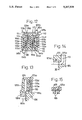
- FIG. 8 shows in a cross section of one of the housings in another embodiment of the connector according to the present invention.
- FIG. 9 is a plan view of the housing of the connector shown in FIG. 8;
- FIG. 10 is a side elevation of the housing of the connector shown in FIG. 8 with a part of the housing shown as removed;
- FIG. 11 is a bottom view of the housing of the connector shown in FIG. 8;
- FIG. 12 shows in a cross section of the connector shown in FIG. 8 with the both housings in engaging state
- FIGS. 13 and 14 are fragmentary sectioned views of dies employed for manufacturing the connector of FIG. 8;
- FIG. 15 is a fragmentary sectioned view of the dies of FIG. 14 taken along line XV-XV;
- FIGS. 16 and 17 are explanatory views for a couple of parts of manufacturing steps of the connector shown in FIG. 8;
- FIG. 18 shows in a perspective view one of the housings employed in a further embodiment of the connector according to the present invention.
- FIG. 19 is a side elevation of the connector of FIG. 18 in the engaging state of the both housings;
- FIG. 20 is a front view of the connector of FIG. 18 in the engaging state
- FIG. 21 shows in a fragmentary perspective view in still another embodiment of the connector according to the present invention, with the both housings shown as disengaged from each other;
- FIG. 22 is a fragmentary sectioned view in locking state of locking metal fittings employed in the connector of FIG. 21.
- a connector 10 comprises a pair of housings 11 and 12, which are formed with a synthetic resin material mutually into an identical configuration, preferably in a box shape.
- the housings 11 and 12 respectively comprise one longitudinal half 11a or 12a and the other longitudinal half 11b or 12b, which two halves 11a and 11b or 12a and 12b are defining between them a groove 11c or 12c, the one half 11a or 12a is formed relatively smaller than the other half 11b or 12b, and the both housings 11 and 12 are formed to be mutually engageable, with the respective halves disposed to interdigitate so that the one half 11a of the one housing 11 will be disposed inside the other half 12b of the other housing 12 while the other half 11b of the one housing 11 will be disposed outside the one half 12a of the other housing 12.
- two arrays of contactors 13 and 14 are provided as disposed along the inner side wall of their one halves 11a and 12a, as seen in FIG. 1, while these contactors 13 and 14 are formed as punched out of flat and thin metal plate and formed substantially into a bar shape with such conducting metal material as a copper alloy and the like, as shown in FIG. 3.
- the respective contactors 13 and 14 are secured at their base portions 13a and 14a as urged into holding holes 15 and 16 made in bottom wall parts of the one halves 11a and 12a while extended ends 13b and 14b out of the bottom wall parts are bent outward into an L-shape.
- the foregoing arrays of the contactors 13, 14 and 17, 18 are respectively made to be the same number of the conductors, so that a concurrent connection of multiple wires may be realized (since the arrangement of the respective arrays of the contactors 13, 14, 17 and 18 are substantially the same and, in FIG. 2, the housing 11 and the contactor array 13 disposed along the one half 11a of the housing 11 only are shown in FIG. 2).
- the extended ends 13b, 14b and 17b, 18b bent into the L-shape are disposed to extend mutually in opposite directions on the bottom wall parts of the housings 11 and 12, that is, adjacent to non-open side of the housings, so as to allow the connector to be easily mounted to, for example, a printed circuit substrate (not shown).
- housings 11 and 12 there are provided upward and downward projections 21a and 21b for positioning the connector to the printed circuit substrate, as well as fixing metal terminals 22a and 22b, preferably, for mounting the connector to the printed circuit substrate (while FIG. 2 shows only the one housing 11, the other housing 12 is formed substantially in the same manner).
- the contactor 13 is formed to have at a free end portion 13c a contacting part 13d bent into an L-shape at a relatively shallow angle and provided with a plating of such a noble metal as gold or the like which is excellent in the electric contact stability.
- a slanted step 13e formed at an angle of about 30 degrees, preferably, so as to allow a reliable clicking action to be attained upon completion of the connection between the respective contactors of the both housing.
- these contacting part 13d and slanted step 13e are formed by means of a bending process with proper dies or the like since, according to such process, the required working can be easily executed even when a sufficient size minimization is attempted, with a higher precisioned work stably executed, in contrast to conventional expanding work.
- At the base portions 13a of the contactor 13 further, there are provided such projections 13f that will frictionally engage with inner face of the holding hole 15.
- All other contactors 14, 17 and 18 are formed in the same manner as the contactor 13 and their respective portions are denoted with the same suffixes as given to the contactor 13 in the drawings.
- the mutually opposing pair of the contactors 13 and 18 or 14 and 17 are made to engage at their contacting parts 13d and 18d or 14d and 17d with a portion closer to the base portions of the opposing contactors, while being resiliently bent by one another, so that, as represented by a solid line curve x of the relationship between the engaging strength and the engaging stroke of FIG. 6, in particular, by a portion between two points B and E of the curve, with the engaging strength between the opposing contactors varied relatively gradually so as to allow the both housings 11 and 12 to be engageable smoothly simply with finger tips or the like.
- the mutually sliding contacting parts 13d and 18d or 14d and 17d are caused to hit and pass the sloped steps 18e and 13e or 17e and 14e (see FIG. 5), upon which the mutual engaging strength is caused to become abruptly large to reach the maximum value and again abruptly smaller as is evident from a portion of the curve x adjacent a point E of FIG. 6, whereby a clicking action is provided to the finger tips so as to allow the completion of the contacting operation sensed by the operator.
- a gradual engagement of the pair of the housings 11 and 12 with each other causes the opposing contactors 13 and 18, for example, initially to hit each other at their contacting parts 13d and 18d as seen in FIG. 7(A), then to be slightly bent in mutually separating direction while keeping mutual engagement as seen in FIG. 7(B), and thereafter to once flex back after passing through the contacting parts 13d and 18d so as to mutually resiliently with each other at two points as seen in FIG. 7(C).
- the engaging strength is caused to vary as represented by a portion between points A and C of the solid line curve x in FIG.
- FIGS. 8 to 12 there is shown another embodiment of the connector according to the present invention, in which the respective arrays of the contactors are secured as integrally molded with the respective housings.
- the substantially identical constituent members with those in the foregoing embodiment of FIGS. 1-7 are denoted by the same reference numerals as used in FIGS. 1-7 but as added by 100.
- the four arrays of the contactors 113, 114, 117 and 118 are formed as bent substantially into a Z-shape at their part from the base portions 113a to the externally extended ends 113b, 114b, 117b and 118b, and are integrally molded along the respective halves 111a, 111b, 112a and 112b of the both housings 111 and 112 as embedded therein at an intermediate portions of the Z-shape bent parts.
- the contactors 113, 114, 117 and 118 are so arranged that their parts including the free end portions 113c, 114c, 117c and 118c having the shallow L-shaped contacting parts 113d, 114d, 117d and 118d as well as the sloped steps 113e, 114e, 117e and 118e are extended along the inner side faces of the housing halves 111a, 111b, 112a and 112b while the other extended ends 113b and 117b out of the housing 111 as well as the extended ends 114b and 118b out of the housing 112 are disposed to extend mutually in opposite directions, for ready mounting of the connector to the printed circuit substrate (not shown).
- the mutual engagement of the both housings 111 and 112 causes the mutually opposing arrays of the contactors 113 and 118 as well as 117 and 114 to resiliently bend each other and eventually to be brought into the reliable contacting state as optimumly resiliently contacted at the two points with each other, throught the substantially the same sequences of the variation in the engaging strength as shown in FIG. 6 and providing the excellent clicking action upon the completion of the connecting operation (as seen particularly in FIG. 12).
- the Z-shaped bending of the respective contactors will be effective to soften any shock applied when the opposing contactors are mutually engaged upon the engagement of the housings 111 and 112.
- the contactors 113, 114, 117 and 118 With the integral molding of the contactors 113, 114, 117 and 118 with the housings 111 and 112, it is made possible to render the length of a range for which the contactors directly contact with the housings to be larger, so as to be able to firmly secure the respective contactors to the housings.
- the contactors are to be partly embedded in the housings as integrally molded therewith, so that a reinforcement can be provided to the housings.
- the contactors are to be firmly secured to the housings while an effective reinforcement of the housings can be realized at their portions where the contactors are molded integrally with the housings, it is made possible to render the thickness of the bottom wall parts of the housings 111 and 112 to be smaller though the through holes 123a, 123b and 124a, 124b are made in the portions, and thus to effectively reduce the entire height of the connector.
- an upper molding die 125 is provided with a recess 125a for accommodating therein the free end part 113c of the contactor 113, a partition 125c is provided to the die 125 between the recess 125b for integrally forming the half 111a of the housing 111 and, along bottom end face of this partition 125c, a so-called parting line, there is provided a groove 125d substantially of an identical width with that of the contactor 113 at its intermediate portion bent into the Z-shape (see FIGS.
- the contactor 113 is thus inserted at the intermediate portion into the groove 125d, and a lower die 126 is fitted to the upper die 125 with a corner of the lower die 126 engaged to a part of the intermediate portion in the base portion 113a of the contactor 113 inserted in the groove 125d of the upper die 125 to thereby close the recess 125a, as shown in FIG. 14.
- the base portion 113a of the contactor 113 inserted in the recess 125b of the upper die 125 and exposed out of the lower die 126 is bent at a proper position, and a synthetic resin is poured into the recess 125b and into a cavity defined between a slide core 126a and the lower die 126, whereby the housing 113 and the intermediate portion at the base portion 113a of the contactor 113 can be integrally molded.
- the other recess 125a of the upper die 125 is closed by the lower die 126 and base portion 113a of the contactor 113 so that no synthetic resin will enter therein.
- the extended end 113b of the contactor 113 is subjected to a bending work at a position closer to the bottom wall face of the housing 111.
- a distance between the bottom wall face of the housing 111 and the bent position at the extended portion 113b of the contactor 113 is kept small, it is made possible to execute reliably a soldering work of the extended end 113b with respect to the printed circuit substrate 127 as shown in FIG. 17 even when the solder 127a is apt to flow upward along the extended end 113b of the contactor 113, without causing a so-called wicking phenomenon as restricted by the bottom wall face of the housing 111.
- the extended ends 113b and 117b as well as 114b and 118b of the respective arrays of the connectors 113 and 114 as well as 114 and 118 respectively disposed to oppose each other are extended mutually in opposite directions so that a space between these extended ends can be well utilized as a vacant space and, in mounting the connector to the printed circuit substrate 127, a highly dense wiring can be provided onto the substrate 127 immediately below the connector.
- FIGS. 18 to 20 there is shown still another embodiment of the connector according to the present invention, in which the both housings 211 and 212 are provided at their both longitudinal end faces with each of a pair of engaging metal fittings 222A and 222B, as secured thereto by means of, for example, an integral molding.
- Each of the metal fittings 222A and 222B comprises a notch 222Aa or 222Ba and a projection 222Ab or 222Bb, so that the projection 222Bb of the metal fitting 222B will engage in the notch 222Aa of the metal fitting 222A while the projection 222Ab of the metal fitting 222A will engage in the notch 222Ba of the metal fitting 222B, whereby, when the both housings 211 and 212 are mutually disconnected, they can be effectively guided in their separating direction by means of the projections and notches even when any twisting force of the like external force is applied, so as to prevent any twisting or the like stress from being given to the housings 211 and 212. Consequently, soldered parts between the connector and the printed circuit substrate can be prevented from being impaired or damaged by the twisting or the like stress.
- the foregoing engaging metal fittings 222A and 222B are made to function also as grounding terminals.
- fixing metal terminals 230 and 230a for mounting the connector to the printed circuit substrate are provided to the both longitudinal ends of the housings as divided to both side edges at each end, so as to allow part 228 of printed circuit pattern on the printed circuit substrate 227 can be disposed between the both-side divided metal terminals 230 or 230a, as shown in FIG. 18, and the effective surface area of providing the circuit pattern can be increased.
- FIGS. 21 and 22 there is shown still another embodiment of the connector according to the present invention, in which engaging metal fittings 322A and 322B are secured to the respective longitudinal ends of the both housings 3111 and 312, while one 322A of the metal fittings is provided with a projection 322Aa and the other metal fitting 322B is made to have a receiving hole 322Ba, so that the projection 322Aa will engage in the receiving hole 322Ba upon engagement of the housings 311 and 312 with each other.
- the both housings 311 and 312 engaged with each other are made into locked state with such engaging metal fittings 322A and 322B, and the connecting parts or the like of the connector with the printed circuit substrate can be prevented from being affected by any externally given stress applied to the housings 311 and 312 and concentrated in particular to the extended terminals of the contactors.
- All other constituent elements and their functions in this embodiment are the same as those in the respective foregoing embodiments, and the same both-side divided provisions of fixing metal fittings 330 and 330a as in the embodiment of FIGS. 18 to 20 can be also adopted in the present instance.
Applications Claiming Priority (4)
| Application Number | Priority Date | Filing Date | Title |
|---|---|---|---|
| JP2-42849[U] | 1990-04-20 | ||
| JP4284990U JPH0472471U (ko) | 1990-04-20 | 1990-04-20 | |
| JP3-30386 | 1991-02-25 | ||
| JP3030386A JP2871128B2 (ja) | 1991-02-25 | 1991-02-25 | コネクタ及びその製造方法 |
Publications (1)
| Publication Number | Publication Date |
|---|---|
| US5167528A true US5167528A (en) | 1992-12-01 |
Family
ID=26368714
Family Applications (1)
| Application Number | Title | Priority Date | Filing Date |
|---|---|---|---|
| US07/685,656 Expired - Lifetime US5167528A (en) | 1990-04-20 | 1991-04-16 | Method of manufacturing an electrical connector |
Country Status (2)
| Country | Link |
|---|---|
| US (1) | US5167528A (ko) |
| KR (1) | KR940007695Y1 (ko) |
Cited By (77)
| Publication number | Priority date | Publication date | Assignee | Title |
|---|---|---|---|---|
| WO1994028599A1 (en) * | 1993-05-20 | 1994-12-08 | Berg Technology, Inc. | Electrical connector |
| EP0658951A1 (en) * | 1993-12-14 | 1995-06-21 | Molex Incorporated | Electrical connector for use in coupling two printed boards |
| WO1996032831A1 (en) * | 1995-04-18 | 1996-10-24 | The Whitaker Corporation | Electrical connector and connector assembly |
| US5575674A (en) * | 1994-07-29 | 1996-11-19 | The Whitaker Corporation | Connector adapted for hermaphroditic construction |
| US5626482A (en) * | 1994-12-15 | 1997-05-06 | Molex Incorporated | Low profile surface mountable electrical connector assembly |
| WO1998000885A1 (en) * | 1996-06-28 | 1998-01-08 | Berg Technology, Inc. | Electrical connector |
| US5772474A (en) * | 1995-09-07 | 1998-06-30 | Molex Incorporated | Electrical connector with embedded terminals |
| US5830018A (en) * | 1995-12-12 | 1998-11-03 | Molex Incorporated | Low profile surface mountable electrical connector assembly |
| US5876217A (en) * | 1996-03-14 | 1999-03-02 | Molex Incorporated | Electric connector assembly with improved retention characteristics |
| US5885092A (en) * | 1996-06-21 | 1999-03-23 | Molex Incorporated | Electric connector assembly with improved registration characteristics |
| US5906518A (en) * | 1995-04-18 | 1999-05-25 | The Whitaker Corporation | Electrical connector and connector assembly |
| EP0926780A2 (en) * | 1997-12-26 | 1999-06-30 | Japan Solderless Terminal Mfg. Co., Ltd. | A connector for a printed circuit board and a production method therefor |
| US6010370A (en) * | 1996-12-20 | 2000-01-04 | Molex Incorporated | Insert molded electrical connector and method for producing same |
| US6219913B1 (en) * | 1997-01-13 | 2001-04-24 | Sumitomo Wiring Systems, Ltd. | Connector producing method and a connector produced by insert molding |
| US6471539B1 (en) * | 2001-12-04 | 2002-10-29 | Hon Hai Precision Ind. Co., Ltd. | Electrical connector couple having mating indication device |
| US20050142922A1 (en) * | 2003-12-25 | 2005-06-30 | Junya Akasaka | Electrical connector assembly |
| US20060019517A1 (en) * | 2001-11-14 | 2006-01-26 | Fci Americas Technology, Inc. | Impedance control in electrical connectors |
| US20060035530A1 (en) * | 2001-11-14 | 2006-02-16 | Fci Americas Technology, Inc. | High speed differential transmission structures without grounds |
| US7000317B1 (en) * | 1999-08-30 | 2006-02-21 | Fci Americas Technology, Inc. | Method for manufacturing electrical connectors for enhancing coplanarity |
| US20060234531A1 (en) * | 2001-11-14 | 2006-10-19 | Fci Americas Technology, Inc. | Shieldless, high-speed electrical connectors |
| US20060286864A1 (en) * | 2005-06-21 | 2006-12-21 | Bethurum Gary C | Electrical Disconnect With Push-In Connectors |
| EP1790042A1 (en) * | 2004-08-13 | 2007-05-30 | Fci | High density, low noise, high speed mezzanine connector |
| US20070155227A1 (en) * | 2005-12-27 | 2007-07-05 | Ddk Ltd. | Electrical connector |
| US20080050949A1 (en) * | 2006-06-21 | 2008-02-28 | Bethurum Gary C | Electrical disconnect with adjacent wire receptacle boxes |
| DE10303072B4 (de) * | 2002-01-29 | 2008-05-08 | Japan Aviation Electronics Industry, Ltd. | Verbinder und Meßgerät |
| US20080203547A1 (en) * | 2007-02-26 | 2008-08-28 | Minich Steven E | Insert molded leadframe assembly |
| US20080207014A1 (en) * | 2005-01-28 | 2008-08-28 | Molex Incorporated | Board Mounted Electrical Connector |
| US7429176B2 (en) | 2001-07-31 | 2008-09-30 | Fci Americas Technology, Inc. | Modular mezzanine connector |
| US7462924B2 (en) | 2006-06-27 | 2008-12-09 | Fci Americas Technology, Inc. | Electrical connector with elongated ground contacts |
| US7497735B2 (en) | 2004-09-29 | 2009-03-03 | Fci Americas Technology, Inc. | High speed connectors that minimize signal skew and crosstalk |
| US7497736B2 (en) | 2006-12-19 | 2009-03-03 | Fci Americas Technology, Inc. | Shieldless, high-speed, low-cross-talk electrical connector |
| US7500871B2 (en) | 2006-08-21 | 2009-03-10 | Fci Americas Technology, Inc. | Electrical connector system with jogged contact tails |
| US7524209B2 (en) | 2003-09-26 | 2009-04-28 | Fci Americas Technology, Inc. | Impedance mating interface for electrical connectors |
| US20090130912A1 (en) * | 2007-11-15 | 2009-05-21 | Fci Americas Technology, Inc. | Electrical connector mating guide |
| US20090181580A1 (en) * | 2005-06-21 | 2009-07-16 | Ideal Industries, Inc. | Electrical disconnect with push-in connectors |
| US20100055988A1 (en) * | 2007-08-30 | 2010-03-04 | Shuey Joseph B | Mezzanine-type electrical connectors |
| US20100075516A1 (en) * | 2008-09-25 | 2010-03-25 | Horchler David C | Hermaphroditic Electrical Connector |
| US7708569B2 (en) | 2006-10-30 | 2010-05-04 | Fci Americas Technology, Inc. | Broadside-coupled signal pair configurations for electrical connectors |
| US7713088B2 (en) | 2006-10-05 | 2010-05-11 | Fci | Broadside-coupled signal pair configurations for electrical connectors |
| US20100167569A1 (en) * | 2008-12-31 | 2010-07-01 | Stoner Stuart C | Gender-Neutral Electrical Connector |
| US7967647B2 (en) * | 2007-02-28 | 2011-06-28 | Fci Americas Technology Llc | Orthogonal header |
| US20110294351A1 (en) * | 2010-05-31 | 2011-12-01 | Hon Hai Precision Industry Co., Ltd. | Board to board connector with low profile |
| US8137119B2 (en) | 2007-07-13 | 2012-03-20 | Fci Americas Technology Llc | Electrical connector system having a continuous ground at the mating interface thereof |
| US8267721B2 (en) | 2009-10-28 | 2012-09-18 | Fci Americas Technology Llc | Electrical connector having ground plates and ground coupling bar |
| US20130102177A1 (en) * | 2011-10-21 | 2013-04-25 | Ohio Associated Enterprises, Llc | Electrical contact with redundant contact points |
| US20130102199A1 (en) * | 2011-10-21 | 2013-04-25 | Ohio Associated Enterprises, Llc | Hermaphroditic interconnect system |
| US8540525B2 (en) | 2008-12-12 | 2013-09-24 | Molex Incorporated | Resonance modifying connector |
| US8545240B2 (en) | 2008-11-14 | 2013-10-01 | Molex Incorporated | Connector with terminals forming differential pairs |
| US8608510B2 (en) | 2009-07-24 | 2013-12-17 | Fci Americas Technology Llc | Dual impedance electrical connector |
| US8616919B2 (en) | 2009-11-13 | 2013-12-31 | Fci Americas Technology Llc | Attachment system for electrical connector |
| US8657616B2 (en) | 2011-05-24 | 2014-02-25 | Fci Americas Technology Llc | Electrical contact normal force increase |
| US8715003B2 (en) | 2009-12-30 | 2014-05-06 | Fci Americas Technology Llc | Electrical connector having impedance tuning ribs |
| US8715005B2 (en) | 2011-03-31 | 2014-05-06 | Hon Hai Precision Industry Co., Ltd. | High speed high density connector assembly |
| US8764464B2 (en) | 2008-02-29 | 2014-07-01 | Fci Americas Technology Llc | Cross talk reduction for high speed electrical connectors |
| USD718253S1 (en) | 2012-04-13 | 2014-11-25 | Fci Americas Technology Llc | Electrical cable connector |
| US8905651B2 (en) | 2012-01-31 | 2014-12-09 | Fci | Dismountable optical coupling device |
| USD720698S1 (en) | 2013-03-15 | 2015-01-06 | Fci Americas Technology Llc | Electrical cable connector |
| US8944831B2 (en) | 2012-04-13 | 2015-02-03 | Fci Americas Technology Llc | Electrical connector having ribbed ground plate with engagement members |
| USD727268S1 (en) | 2012-04-13 | 2015-04-21 | Fci Americas Technology Llc | Vertical electrical connector |
| USD727852S1 (en) | 2012-04-13 | 2015-04-28 | Fci Americas Technology Llc | Ground shield for a right angle electrical connector |
| US9048583B2 (en) | 2009-03-19 | 2015-06-02 | Fci Americas Technology Llc | Electrical connector having ribbed ground plate |
| USD733662S1 (en) | 2013-01-25 | 2015-07-07 | Fci Americas Technology Llc | Connector housing for electrical connector |
| US9136634B2 (en) | 2010-09-03 | 2015-09-15 | Fci Americas Technology Llc | Low-cross-talk electrical connector |
| USD746236S1 (en) | 2012-07-11 | 2015-12-29 | Fci Americas Technology Llc | Electrical connector housing |
| US9257778B2 (en) | 2012-04-13 | 2016-02-09 | Fci Americas Technology | High speed electrical connector |
| US9277649B2 (en) | 2009-02-26 | 2016-03-01 | Fci Americas Technology Llc | Cross talk reduction for high-speed electrical connectors |
| US20160233708A1 (en) * | 2013-09-12 | 2016-08-11 | Kimree Hi-Tech Inc. | Electronic cigarette charging apparatus |
| CN105977678A (zh) * | 2016-04-29 | 2016-09-28 | 中航光电科技股份有限公司 | 一种导电接触件及使用该导电接触件的电连接器 |
| US9543703B2 (en) | 2012-07-11 | 2017-01-10 | Fci Americas Technology Llc | Electrical connector with reduced stack height |
| US20170214183A1 (en) * | 2016-01-25 | 2017-07-27 | Yazaki Corporation | Accommodation confirming structure for electronic component, electrical connection box, and wire harness |
| CN107134677A (zh) * | 2016-02-26 | 2017-09-05 | 莫列斯有限公司 | 电连接器及电连接器组合 |
| DE202017003723U1 (de) * | 2017-07-14 | 2018-10-16 | WAGO Verwaltungsgesellschaft mit beschränkter Haftung | Steckverbinder |
| CN110247213A (zh) * | 2018-03-08 | 2019-09-17 | 广濑电机株式会社 | 中间电连接器及电连接器组装体 |
| CN107809018B (zh) * | 2016-09-09 | 2020-09-29 | 广濑电机株式会社 | 电路基板用电连接器以及电路基板用电连接器组装体 |
| US10868396B1 (en) * | 2019-06-26 | 2020-12-15 | Te Connectivity Corporation | Small pitch high-speed connectors |
| US10998655B2 (en) | 2016-04-28 | 2021-05-04 | Panasonic Intellectual Property Management Co., Ltd. | Connector and connection system |
| US11431120B2 (en) * | 2020-03-16 | 2022-08-30 | Foxconn (Kunshan) Computer Connector Co., Ltd. | Terminal module and mating assembly thereof |
Citations (4)
| Publication number | Priority date | Publication date | Assignee | Title |
|---|---|---|---|---|
| US4337574A (en) * | 1978-12-14 | 1982-07-06 | Amp Incorporated | Method of manufacturing electrical connector receptacles |
| JPH0195672A (ja) * | 1987-10-08 | 1989-04-13 | Sony Corp | カラー画像のデータ圧縮方法 |
| US4863402A (en) * | 1986-10-17 | 1989-09-05 | Ohio Associated Enterprises, Inc. | Method and apparatus for making electrical connecting device |
| US5074039A (en) * | 1990-10-26 | 1991-12-24 | Amp Incorporated | Method of manufacturing electrical connectors |
-
1991
- 1991-04-16 US US07/685,656 patent/US5167528A/en not_active Expired - Lifetime
- 1991-04-20 KR KR2019910005474U patent/KR940007695Y1/ko not_active IP Right Cessation
Patent Citations (4)
| Publication number | Priority date | Publication date | Assignee | Title |
|---|---|---|---|---|
| US4337574A (en) * | 1978-12-14 | 1982-07-06 | Amp Incorporated | Method of manufacturing electrical connector receptacles |
| US4863402A (en) * | 1986-10-17 | 1989-09-05 | Ohio Associated Enterprises, Inc. | Method and apparatus for making electrical connecting device |
| JPH0195672A (ja) * | 1987-10-08 | 1989-04-13 | Sony Corp | カラー画像のデータ圧縮方法 |
| US5074039A (en) * | 1990-10-26 | 1991-12-24 | Amp Incorporated | Method of manufacturing electrical connectors |
Non-Patent Citations (1)
| Title |
|---|
| IBM Technical Bulletin, vol. 1, No. 4, Dec. 1958. * |
Cited By (132)
| Publication number | Priority date | Publication date | Assignee | Title |
|---|---|---|---|---|
| WO1994028599A1 (en) * | 1993-05-20 | 1994-12-08 | Berg Technology, Inc. | Electrical connector |
| US5842875A (en) * | 1993-12-14 | 1998-12-01 | Molex Incorporated | Electric connector assembly for use in coupling two printed boards |
| EP0658951A1 (en) * | 1993-12-14 | 1995-06-21 | Molex Incorporated | Electrical connector for use in coupling two printed boards |
| US5639248A (en) * | 1993-12-14 | 1997-06-17 | Molex Incorporated | Electric connector assembly for use in couplings two printed boards |
| US5641290A (en) * | 1993-12-14 | 1997-06-24 | Molex Incorporated | Electric connector assembly for use in coupling two printed boards |
| US5575674A (en) * | 1994-07-29 | 1996-11-19 | The Whitaker Corporation | Connector adapted for hermaphroditic construction |
| US5626482A (en) * | 1994-12-15 | 1997-05-06 | Molex Incorporated | Low profile surface mountable electrical connector assembly |
| WO1996032831A1 (en) * | 1995-04-18 | 1996-10-24 | The Whitaker Corporation | Electrical connector and connector assembly |
| US5906518A (en) * | 1995-04-18 | 1999-05-25 | The Whitaker Corporation | Electrical connector and connector assembly |
| US5772474A (en) * | 1995-09-07 | 1998-06-30 | Molex Incorporated | Electrical connector with embedded terminals |
| US5830018A (en) * | 1995-12-12 | 1998-11-03 | Molex Incorporated | Low profile surface mountable electrical connector assembly |
| US5876217A (en) * | 1996-03-14 | 1999-03-02 | Molex Incorporated | Electric connector assembly with improved retention characteristics |
| US5885092A (en) * | 1996-06-21 | 1999-03-23 | Molex Incorporated | Electric connector assembly with improved registration characteristics |
| WO1998000885A1 (en) * | 1996-06-28 | 1998-01-08 | Berg Technology, Inc. | Electrical connector |
| US6010370A (en) * | 1996-12-20 | 2000-01-04 | Molex Incorporated | Insert molded electrical connector and method for producing same |
| US6219913B1 (en) * | 1997-01-13 | 2001-04-24 | Sumitomo Wiring Systems, Ltd. | Connector producing method and a connector produced by insert molding |
| EP0926780A2 (en) * | 1997-12-26 | 1999-06-30 | Japan Solderless Terminal Mfg. Co., Ltd. | A connector for a printed circuit board and a production method therefor |
| EP0926780A3 (en) * | 1997-12-26 | 2000-10-11 | Japan Solderless Terminal Mfg. Co., Ltd. | A connector for a printed circuit board and a production method therefor |
| US7000317B1 (en) * | 1999-08-30 | 2006-02-21 | Fci Americas Technology, Inc. | Method for manufacturing electrical connectors for enhancing coplanarity |
| US8056225B2 (en) * | 1999-08-30 | 2011-11-15 | Fci Americas Technology, Inc. | Method for manufacturing electrical connectors for enhancing coplanarity |
| US20060075634A1 (en) * | 1999-08-30 | 2006-04-13 | Berg Technology, Inc. | Method for manufacturing electrical connectors for enhancing coplanarity |
| US7429176B2 (en) | 2001-07-31 | 2008-09-30 | Fci Americas Technology, Inc. | Modular mezzanine connector |
| US20060019517A1 (en) * | 2001-11-14 | 2006-01-26 | Fci Americas Technology, Inc. | Impedance control in electrical connectors |
| US20060035530A1 (en) * | 2001-11-14 | 2006-02-16 | Fci Americas Technology, Inc. | High speed differential transmission structures without grounds |
| US20060234531A1 (en) * | 2001-11-14 | 2006-10-19 | Fci Americas Technology, Inc. | Shieldless, high-speed electrical connectors |
| US7390200B2 (en) | 2001-11-14 | 2008-06-24 | Fci Americas Technology, Inc. | High speed differential transmission structures without grounds |
| US7467955B2 (en) | 2001-11-14 | 2008-12-23 | Fci Americas Technology, Inc. | Impedance control in electrical connectors |
| US7442054B2 (en) | 2001-11-14 | 2008-10-28 | Fci Americas Technology, Inc. | Electrical connectors having differential signal pairs configured to reduce cross-talk on adjacent pairs |
| US7331800B2 (en) | 2001-11-14 | 2008-02-19 | Fci Americas Technology, Inc. | Shieldless, high-speed electrical connectors |
| US6471539B1 (en) * | 2001-12-04 | 2002-10-29 | Hon Hai Precision Ind. Co., Ltd. | Electrical connector couple having mating indication device |
| DE10303072B4 (de) * | 2002-01-29 | 2008-05-08 | Japan Aviation Electronics Industry, Ltd. | Verbinder und Meßgerät |
| US7837504B2 (en) | 2003-09-26 | 2010-11-23 | Fci Americas Technology, Inc. | Impedance mating interface for electrical connectors |
| US7524209B2 (en) | 2003-09-26 | 2009-04-28 | Fci Americas Technology, Inc. | Impedance mating interface for electrical connectors |
| US20050142922A1 (en) * | 2003-12-25 | 2005-06-30 | Junya Akasaka | Electrical connector assembly |
| EP1790042A4 (en) * | 2004-08-13 | 2007-10-03 | Framatome Connectors Int | VERY FAST, HIGH DENSITY, LOW NOISE MEZZANINE TYPE CONNECTOR |
| EP1790042A1 (en) * | 2004-08-13 | 2007-05-30 | Fci | High density, low noise, high speed mezzanine connector |
| US7497735B2 (en) | 2004-09-29 | 2009-03-03 | Fci Americas Technology, Inc. | High speed connectors that minimize signal skew and crosstalk |
| US20080207014A1 (en) * | 2005-01-28 | 2008-08-28 | Molex Incorporated | Board Mounted Electrical Connector |
| US7658636B2 (en) | 2005-01-28 | 2010-02-09 | Molex Incorporated | Board mounted electrical connector |
| US20090227132A1 (en) * | 2005-06-21 | 2009-09-10 | Ideal Industries, Inc. | Electrical Disconnect with Push-In Connectors |
| US7771217B2 (en) | 2005-06-21 | 2010-08-10 | Ideal Industries, Inc. | Electrical disconnect with push-in connectors |
| US20090017694A1 (en) * | 2005-06-21 | 2009-01-15 | Bethurum Gary C | Electrical disconnect with push-in connectors |
| US7753718B2 (en) | 2005-06-21 | 2010-07-13 | Ideal Industries, Inc. | Electrical disconnect with push-in connectors |
| US20060286864A1 (en) * | 2005-06-21 | 2006-12-21 | Bethurum Gary C | Electrical Disconnect With Push-In Connectors |
| US7887353B2 (en) | 2005-06-21 | 2011-02-15 | Ideal Industries, Inc. | Electrical disconnect with push-in connectors |
| US7988481B2 (en) * | 2005-06-21 | 2011-08-02 | Ideal Industries, Inc. | Electrical disconnect with push-in connectors |
| US20090181580A1 (en) * | 2005-06-21 | 2009-07-16 | Ideal Industries, Inc. | Electrical disconnect with push-in connectors |
| US7540770B2 (en) * | 2005-12-27 | 2009-06-02 | Ddk Ltd. | Electrical connector |
| US20070155227A1 (en) * | 2005-12-27 | 2007-07-05 | Ddk Ltd. | Electrical connector |
| US7727002B2 (en) | 2006-06-21 | 2010-06-01 | Ideal Industries, Inc. | Electrical disconnect with adjacent wire receptacle boxes |
| US20080050949A1 (en) * | 2006-06-21 | 2008-02-28 | Bethurum Gary C | Electrical disconnect with adjacent wire receptacle boxes |
| US7462924B2 (en) | 2006-06-27 | 2008-12-09 | Fci Americas Technology, Inc. | Electrical connector with elongated ground contacts |
| US7500871B2 (en) | 2006-08-21 | 2009-03-10 | Fci Americas Technology, Inc. | Electrical connector system with jogged contact tails |
| US7837505B2 (en) | 2006-08-21 | 2010-11-23 | Fci Americas Technology Llc | Electrical connector system with jogged contact tails |
| US7713088B2 (en) | 2006-10-05 | 2010-05-11 | Fci | Broadside-coupled signal pair configurations for electrical connectors |
| US7708569B2 (en) | 2006-10-30 | 2010-05-04 | Fci Americas Technology, Inc. | Broadside-coupled signal pair configurations for electrical connectors |
| US8678860B2 (en) | 2006-12-19 | 2014-03-25 | Fci Americas Technology Llc | Shieldless, high-speed, low-cross-talk electrical connector |
| US7497736B2 (en) | 2006-12-19 | 2009-03-03 | Fci Americas Technology, Inc. | Shieldless, high-speed, low-cross-talk electrical connector |
| US7762843B2 (en) | 2006-12-19 | 2010-07-27 | Fci Americas Technology, Inc. | Shieldless, high-speed, low-cross-talk electrical connector |
| US8096832B2 (en) | 2006-12-19 | 2012-01-17 | Fci Americas Technology Llc | Shieldless, high-speed, low-cross-talk electrical connector |
| US8382521B2 (en) | 2006-12-19 | 2013-02-26 | Fci Americas Technology Llc | Shieldless, high-speed, low-cross-talk electrical connector |
| US20080203547A1 (en) * | 2007-02-26 | 2008-08-28 | Minich Steven E | Insert molded leadframe assembly |
| US8057267B2 (en) | 2007-02-28 | 2011-11-15 | Fci Americas Technology Llc | Orthogonal header |
| US7967647B2 (en) * | 2007-02-28 | 2011-06-28 | Fci Americas Technology Llc | Orthogonal header |
| US8137119B2 (en) | 2007-07-13 | 2012-03-20 | Fci Americas Technology Llc | Electrical connector system having a continuous ground at the mating interface thereof |
| US8147268B2 (en) * | 2007-08-30 | 2012-04-03 | Fci Americas Technology Llc | Mezzanine-type electrical connectors |
| US20100055988A1 (en) * | 2007-08-30 | 2010-03-04 | Shuey Joseph B | Mezzanine-type electrical connectors |
| US20090130912A1 (en) * | 2007-11-15 | 2009-05-21 | Fci Americas Technology, Inc. | Electrical connector mating guide |
| US8147254B2 (en) | 2007-11-15 | 2012-04-03 | Fci Americas Technology Llc | Electrical connector mating guide |
| US8764464B2 (en) | 2008-02-29 | 2014-07-01 | Fci Americas Technology Llc | Cross talk reduction for high speed electrical connectors |
| US8277241B2 (en) | 2008-09-25 | 2012-10-02 | Fci Americas Technology Llc | Hermaphroditic electrical connector |
| US20100075516A1 (en) * | 2008-09-25 | 2010-03-25 | Horchler David C | Hermaphroditic Electrical Connector |
| US8545240B2 (en) | 2008-11-14 | 2013-10-01 | Molex Incorporated | Connector with terminals forming differential pairs |
| US8540525B2 (en) | 2008-12-12 | 2013-09-24 | Molex Incorporated | Resonance modifying connector |
| US8651881B2 (en) | 2008-12-12 | 2014-02-18 | Molex Incorporated | Resonance modifying connector |
| US8992237B2 (en) | 2008-12-12 | 2015-03-31 | Molex Incorporated | Resonance modifying connector |
| US20100167569A1 (en) * | 2008-12-31 | 2010-07-01 | Stoner Stuart C | Gender-Neutral Electrical Connector |
| US7976326B2 (en) | 2008-12-31 | 2011-07-12 | Fci Americas Technology Llc | Gender-neutral electrical connector |
| US9277649B2 (en) | 2009-02-26 | 2016-03-01 | Fci Americas Technology Llc | Cross talk reduction for high-speed electrical connectors |
| US9048583B2 (en) | 2009-03-19 | 2015-06-02 | Fci Americas Technology Llc | Electrical connector having ribbed ground plate |
| US9461410B2 (en) | 2009-03-19 | 2016-10-04 | Fci Americas Technology Llc | Electrical connector having ribbed ground plate |
| US10096921B2 (en) | 2009-03-19 | 2018-10-09 | Fci Usa Llc | Electrical connector having ribbed ground plate |
| US10720721B2 (en) | 2009-03-19 | 2020-07-21 | Fci Usa Llc | Electrical connector having ribbed ground plate |
| US8608510B2 (en) | 2009-07-24 | 2013-12-17 | Fci Americas Technology Llc | Dual impedance electrical connector |
| US8267721B2 (en) | 2009-10-28 | 2012-09-18 | Fci Americas Technology Llc | Electrical connector having ground plates and ground coupling bar |
| US8616919B2 (en) | 2009-11-13 | 2013-12-31 | Fci Americas Technology Llc | Attachment system for electrical connector |
| US8715003B2 (en) | 2009-12-30 | 2014-05-06 | Fci Americas Technology Llc | Electrical connector having impedance tuning ribs |
| US8192217B2 (en) * | 2010-05-31 | 2012-06-05 | Hon Hai Precision Ind. Co., Ltd | Board to board connector with low profile |
| US20110294351A1 (en) * | 2010-05-31 | 2011-12-01 | Hon Hai Precision Industry Co., Ltd. | Board to board connector with low profile |
| US9136634B2 (en) | 2010-09-03 | 2015-09-15 | Fci Americas Technology Llc | Low-cross-talk electrical connector |
| US8715005B2 (en) | 2011-03-31 | 2014-05-06 | Hon Hai Precision Industry Co., Ltd. | High speed high density connector assembly |
| US8657616B2 (en) | 2011-05-24 | 2014-02-25 | Fci Americas Technology Llc | Electrical contact normal force increase |
| US20150180153A1 (en) * | 2011-10-21 | 2015-06-25 | Ohio Associated Enterprises, Llc | Hermaphroditic interconnect system |
| US20130102177A1 (en) * | 2011-10-21 | 2013-04-25 | Ohio Associated Enterprises, Llc | Electrical contact with redundant contact points |
| US8998645B2 (en) * | 2011-10-21 | 2015-04-07 | Ohio Associated Enterprises, Llc | Hermaphroditic interconnect system |
| US20130102199A1 (en) * | 2011-10-21 | 2013-04-25 | Ohio Associated Enterprises, Llc | Hermaphroditic interconnect system |
| US9472881B2 (en) * | 2011-10-21 | 2016-10-18 | Ohio Associates Enterpries, LLC | Hermaphroditic interconnect system |
| US8905651B2 (en) | 2012-01-31 | 2014-12-09 | Fci | Dismountable optical coupling device |
| US9257778B2 (en) | 2012-04-13 | 2016-02-09 | Fci Americas Technology | High speed electrical connector |
| USD727852S1 (en) | 2012-04-13 | 2015-04-28 | Fci Americas Technology Llc | Ground shield for a right angle electrical connector |
| US9831605B2 (en) | 2012-04-13 | 2017-11-28 | Fci Americas Technology Llc | High speed electrical connector |
| USD748063S1 (en) | 2012-04-13 | 2016-01-26 | Fci Americas Technology Llc | Electrical ground shield |
| USD727268S1 (en) | 2012-04-13 | 2015-04-21 | Fci Americas Technology Llc | Vertical electrical connector |
| USD750025S1 (en) | 2012-04-13 | 2016-02-23 | Fci Americas Technology Llc | Vertical electrical connector |
| USD750030S1 (en) | 2012-04-13 | 2016-02-23 | Fci Americas Technology Llc | Electrical cable connector |
| USD816044S1 (en) | 2012-04-13 | 2018-04-24 | Fci Americas Technology Llc | Electrical cable connector |
| US8944831B2 (en) | 2012-04-13 | 2015-02-03 | Fci Americas Technology Llc | Electrical connector having ribbed ground plate with engagement members |
| USD790471S1 (en) | 2012-04-13 | 2017-06-27 | Fci Americas Technology Llc | Vertical electrical connector |
| USD718253S1 (en) | 2012-04-13 | 2014-11-25 | Fci Americas Technology Llc | Electrical cable connector |
| US9871323B2 (en) | 2012-07-11 | 2018-01-16 | Fci Americas Technology Llc | Electrical connector with reduced stack height |
| US9543703B2 (en) | 2012-07-11 | 2017-01-10 | Fci Americas Technology Llc | Electrical connector with reduced stack height |
| USD751507S1 (en) | 2012-07-11 | 2016-03-15 | Fci Americas Technology Llc | Electrical connector |
| USD746236S1 (en) | 2012-07-11 | 2015-12-29 | Fci Americas Technology Llc | Electrical connector housing |
| USD766832S1 (en) | 2013-01-25 | 2016-09-20 | Fci Americas Technology Llc | Electrical connector |
| USD733662S1 (en) | 2013-01-25 | 2015-07-07 | Fci Americas Technology Llc | Connector housing for electrical connector |
| USD772168S1 (en) | 2013-01-25 | 2016-11-22 | Fci Americas Technology Llc | Connector housing for electrical connector |
| USD745852S1 (en) | 2013-01-25 | 2015-12-22 | Fci Americas Technology Llc | Electrical connector |
| USD720698S1 (en) | 2013-03-15 | 2015-01-06 | Fci Americas Technology Llc | Electrical cable connector |
| US20160233708A1 (en) * | 2013-09-12 | 2016-08-11 | Kimree Hi-Tech Inc. | Electronic cigarette charging apparatus |
| US9837840B2 (en) * | 2013-09-12 | 2017-12-05 | Huizhou Kimree Technology Co., Ltd. Shenzhen Branch | Electronic cigarette charging apparatus |
| US20170214183A1 (en) * | 2016-01-25 | 2017-07-27 | Yazaki Corporation | Accommodation confirming structure for electronic component, electrical connection box, and wire harness |
| US9774141B2 (en) * | 2016-01-25 | 2017-09-26 | Yazaki Corporation | Accommodation confirming structure for electronic component, electrical connection box, and wire harness |
| CN107134677A (zh) * | 2016-02-26 | 2017-09-05 | 莫列斯有限公司 | 电连接器及电连接器组合 |
| CN107134677B (zh) * | 2016-02-26 | 2019-06-07 | 莫列斯有限公司 | 电连接器及电连接器组合 |
| US10998655B2 (en) | 2016-04-28 | 2021-05-04 | Panasonic Intellectual Property Management Co., Ltd. | Connector and connection system |
| CN105977678A (zh) * | 2016-04-29 | 2016-09-28 | 中航光电科技股份有限公司 | 一种导电接触件及使用该导电接触件的电连接器 |
| CN107809018B (zh) * | 2016-09-09 | 2020-09-29 | 广濑电机株式会社 | 电路基板用电连接器以及电路基板用电连接器组装体 |
| DE202017003723U1 (de) * | 2017-07-14 | 2018-10-16 | WAGO Verwaltungsgesellschaft mit beschränkter Haftung | Steckverbinder |
| CN110247213A (zh) * | 2018-03-08 | 2019-09-17 | 广濑电机株式会社 | 中间电连接器及电连接器组装体 |
| CN110247213B (zh) * | 2018-03-08 | 2022-02-22 | 广濑电机株式会社 | 中间电连接器及电连接器组装体 |
| US10868396B1 (en) * | 2019-06-26 | 2020-12-15 | Te Connectivity Corporation | Small pitch high-speed connectors |
| US11431120B2 (en) * | 2020-03-16 | 2022-08-30 | Foxconn (Kunshan) Computer Connector Co., Ltd. | Terminal module and mating assembly thereof |
Also Published As
| Publication number | Publication date |
|---|---|
| KR910018984U (ko) | 1991-11-29 |
| KR940007695Y1 (ko) | 1994-10-22 |
Similar Documents
| Publication | Publication Date | Title |
|---|---|---|
| US5167528A (en) | Method of manufacturing an electrical connector | |
| US5342205A (en) | Electric connector in which a plurality of contact members can be readily assembled to an insulator | |
| US5902136A (en) | Electrical connector for use in miniaturized, high density, and high pin count applications and method of manufacture | |
| US5154634A (en) | Connector holding device | |
| US5535513A (en) | Method for making surface mountable connectors | |
| US5380225A (en) | Electrical connector | |
| JPH10189079A (ja) | コネクタモジュール | |
| US3777301A (en) | Terminals and connectors for interconnecting conductors and male contacts | |
| US6368158B1 (en) | Electric connector having integrally molded terminals and guide pins | |
| KR20200104727A (ko) | 플러그 커넥터 | |
| US4692120A (en) | Electronic card for sharing the same edgeboard connector with another electronic edgeboard | |
| EP0047095A2 (en) | A connector for a leadless electronic package | |
| JP3396799B2 (ja) | メモリカードの接地端子付きコンタクトの製造方法 | |
| JP3961937B2 (ja) | 基板用電気コネクタ | |
| US6857911B2 (en) | Common-use connector for multiple purpose and method of manufacturing the connector | |
| CA1229178A (en) | Low profile stacking connector for printed circuit boards | |
| KR20200104726A (ko) | 플러그 커넥터 | |
| US4595805A (en) | Switch structure comprising recessed contacts | |
| US7021956B2 (en) | Insulation displacement terminal | |
| JPS62202478A (ja) | プラグ | |
| JP2000058166A (ja) | コネクタ及びその製造方法 | |
| JP2560143Y2 (ja) | Fpc接続用コネクタ | |
| JP7248453B2 (ja) | ジョイントコネクタ | |
| JP2771841B2 (ja) | 電気接続器具 | |
| JPH034466A (ja) | コンタクトピン |
Legal Events
| Date | Code | Title | Description |
|---|---|---|---|
| AS | Assignment |
Owner name: MATSUSHITA ELECTRIC WORKS, LTD., 1048, OAZA-KADOMA Free format text: ASSIGNMENT OF ASSIGNORS INTEREST.;ASSIGNORS:NISHIYAMA, YOUICHI;ONO, HISAHIRO;REEL/FRAME:005680/0516 Effective date: 19910404 |
|
| STCF | Information on status: patent grant |
Free format text: PATENTED CASE |
|
| FPAY | Fee payment |
Year of fee payment: 4 |
|
| FPAY | Fee payment |
Year of fee payment: 8 |
|
| FPAY | Fee payment |
Year of fee payment: 12 |
|
| AS | Assignment |
Owner name: PANASONIC ELECTRIC WORKS CO., LTD., JAPAN Free format text: CHANGE OF NAME;ASSIGNOR:MATSUSHITA ELECTRIC WORKS, LTD.;REEL/FRAME:022288/0703 Effective date: 20081001 |