US5082078A - Structure of a front body of a motor vehicle and a method of assembling a vehicle body - Google Patents
Structure of a front body of a motor vehicle and a method of assembling a vehicle body Download PDFInfo
- Publication number
- US5082078A US5082078A US07/632,769 US63276990A US5082078A US 5082078 A US5082078 A US 5082078A US 63276990 A US63276990 A US 63276990A US 5082078 A US5082078 A US 5082078A
- Authority
- US
- United States
- Prior art keywords
- vehicle body
- unit
- cowl
- dash
- wall part
- Prior art date
- Legal status (The legal status is an assumption and is not a legal conclusion. Google has not performed a legal analysis and makes no representation as to the accuracy of the status listed.)
- Expired - Lifetime
Links
- 238000000034 method Methods 0.000 title claims description 12
- 238000010276 construction Methods 0.000 claims abstract description 23
- 239000000463 material Substances 0.000 claims description 18
- 125000006850 spacer group Chemical group 0.000 claims description 10
- 230000002787 reinforcement Effects 0.000 claims description 7
- 238000004378 air conditioning Methods 0.000 claims description 5
- 239000012212 insulator Substances 0.000 claims description 4
- 239000004576 sand Substances 0.000 claims 1
- 230000035939 shock Effects 0.000 abstract description 4
- 239000011521 glass Substances 0.000 description 7
- 238000009434 installation Methods 0.000 description 5
- 238000010586 diagram Methods 0.000 description 3
- 230000004048 modification Effects 0.000 description 2
- 238000012986 modification Methods 0.000 description 2
- 238000005192 partition Methods 0.000 description 2
- 230000001133 acceleration Effects 0.000 description 1
- 238000004519 manufacturing process Methods 0.000 description 1
- 238000005728 strengthening Methods 0.000 description 1
Images


Classifications
-
- B—PERFORMING OPERATIONS; TRANSPORTING
- B62—LAND VEHICLES FOR TRAVELLING OTHERWISE THAN ON RAILS
- B62D—MOTOR VEHICLES; TRAILERS
- B62D25/00—Superstructure or monocoque structure sub-units; Parts or details thereof not otherwise provided for
- B62D25/08—Front or rear portions
-
- B—PERFORMING OPERATIONS; TRANSPORTING
- B62—LAND VEHICLES FOR TRAVELLING OTHERWISE THAN ON RAILS
- B62D—MOTOR VEHICLES; TRAILERS
- B62D25/00—Superstructure or monocoque structure sub-units; Parts or details thereof not otherwise provided for
- B62D25/08—Front or rear portions
- B62D25/081—Cowls
-
- B—PERFORMING OPERATIONS; TRANSPORTING
- B62—LAND VEHICLES FOR TRAVELLING OTHERWISE THAN ON RAILS
- B62D—MOTOR VEHICLES; TRAILERS
- B62D25/00—Superstructure or monocoque structure sub-units; Parts or details thereof not otherwise provided for
- B62D25/08—Front or rear portions
- B62D25/14—Dashboards as superstructure sub-units
-
- B—PERFORMING OPERATIONS; TRANSPORTING
- B62—LAND VEHICLES FOR TRAVELLING OTHERWISE THAN ON RAILS
- B62D—MOTOR VEHICLES; TRAILERS
- B62D65/00—Designing, manufacturing, e.g. assembling, facilitating disassembly, or structurally modifying motor vehicles or trailers, not otherwise provided for
- B62D65/02—Joining sub-units or components to, or positioning sub-units or components with respect to, body shell or other sub-units or components
- B62D65/14—Joining sub-units or components to, or positioning sub-units or components with respect to, body shell or other sub-units or components the sub-units or components being passenger compartment fittings, e.g. seats, linings, trim, instrument panels
Definitions
- the present invention relates to a front body of a motor vehicle wherein two units are provided around a dash panel, which partitions a engine compartment from a passenger compartment, and a method of assembling a vehicle body.
- the Japanese Patent Application Laying Open Gazette No. 59-206267 proposed another incorporated unit including a cowl panel and a dash panel mounted in the vehicle body from the upper side through an opening of a front windshield.
- the object of the present invention is to provide a structure of a front body of a motor vehicle and a method of assembling a vehicle body to improve the operational efficiency of assembling a motor vehicle without damaging the configulation of side part of the instrument panel and endurance efficiency for a head-on collision.
- the present invention comprises such a structure for front body of motor vehicle to achieve the above object as described below.
- a vehicle body side member of a closed sectional construction extending in the widthwise direction of a vehicle body between right and left front pillars of the vehicle body is provided. Also, a first unit having at least a cowl member and a windshield wiper system installed on the cowl member is fitted in the front of the vehicle body side member and a second unit having at least an instrument panel and a steering system is fitted in the rear of the vehicle body side member. Each end of both units is fixed to the vehicle body by tightening bolts.
- a method of assembling a motor vehicle body comprises steps as fellows: inserting the first unit from the upper side and both ends of the unit is fixed to the vehicle body by tightening bolts, which first unit comprises at least a cowl member and a windshield wiper system installed on the cowl member in the front of the vehicle body side member of a closed sectional construction which connects between front pillars and extends in the widthwise direction of the vehicle body from the upper side and inserting the second unit to a passenger compartment from an opening of the vehicle door to be disposed in the rear of the vehicle body side member of the above closed sectional construction and both ends of the units are fixed to the vehicle body by tightening bolts, which second unit comprises at least an instrument panel and a steering system.
- the first unit can be mounted from the upper side and the second unit can be mounted from the rear separately with high assembling efficiency. Moreover, since the vehicle body side member of the closed sectional construction is provided between right and left front pillars of the body, there is less possibility that units move to the passenger compartment in case of a head-on collision, etc.
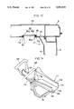
- FIGS. 1-7 show the first embodiment of the present invention: in which
- FIG. 1 is an exploded perspective diagram showing the relationship of location of installation between the cowl unit and the instrument panel unit to the vehicle body;
- FIG. 2 is a sectional view wherein the cowl unit is mounted to the vehicle body
- FIG. 3 is a exploded perspective diagram of a connecting part between the cowl unit and the vehicle body
- FIG. 4 is a sectional view of the side connecting part of the cowl unit in the vehicle body
- FIG. 5 is a perspective view showing the structure of installation of a instrument panel unit in the vehicle body
- FIG. 6 is a sectional view taken along the line A--A' of FIG. 5;
- FIG. 7 is an elevational view as viewed from the engine compartment wherein cowl unit is mounted to the vehicle body.
- FIG. 8 is a sectional view showing the modification of the mounting structure of the dash member of the cowl unit and a dash panel.
- FIGS. 9-14 show the second embodiment: in which
- FIG. 9 is a perspective view showing around the cowl side part of the vehicle body.
- FIG. 10 is an exploded perspective diagram of FIG. 9;
- FIGS. 11, 12, and 13 show sectional views taken along lines B--B, C--C, and D--D respectively of FIG. 9;
- FIG. 14 is a perspective view of the side part of the cowl member in the unit side.
- FIGS. 15-17 show the third embodiment: in which
- FIG. 15 corresponds to FIG. 2;
- FIG. 16 is a perspective view showing mounting the cowl unit to the vehicle body.
- FIG. 17 is a perspective view showing the installation of the second bracket.
- FIG. 18 shows the forth embodiment and corresponds to FIG. 2.
- FIGS. 19 and 20 show the fifth embodiment: in which
- FIG. 19 corresponds to FIG. 2;
- FIG. 20 is a sectional view taken along the line E--E of FIG. 19.
- FIGS. 1-7 show a structure of a front vehicle body of the preferred embodiment.
- reference numeral 1 designates a vehicle body wherein a vehicle body side cowl member 5 extending in the widthwise direction of the vehicle body is provided on a dash panel 4 which partitions a engine compartment 2 from a passenger compartment 3. Both ends of the vehicle body side cowl member 5 are attached fixedly to right and left front pillars 6 of the vehicle body 1. A part of the dash panel 4 is cut and forms an opening 4a.
- the reference numeral 7 designates right and left front fenders.
- cowl unit U 1 In the front of the above vehicle body side cowl member 5 the first unit, cowl unit U 1 , is inserted from the upper side and in the rear of the cowl member 5 the second unit, instrument panel unit U 2 , is inserted into a passenger compartment 3 from an opening of door 1a of the vehicle body 1. Both ends of units U 1 and U 2 are fixed to the vehicle body 1 by tightening bolts.
- the above vehicle body side cowl member 5 has a closed sectional construction wherein an upper panel 8 and a lower panel 9 are attached as shown in FIG. 2.
- the above upper panel 8 is composed of a vertical wall part 8a extending in about the vertical direction, a supporting part 8b extending upwardly and obliquely to the rear from the upper edge of a vertical wall part 8a in order to support around the lower end of the wind shield 10, and an upper wall part 8c extending rearward from the rear end of a supporting part 8b.
- the above lower panel 9 is composed of a bottom wall part 9a extending in the longitudinal direction and attached to the lowermost end of the upper wall part 8a of the above upper panel 8, a vertical wall member 9b standing up from the rear end of the bottom wall part 9a and extending upwardly, and a flange part 9c extending rearwardly from the uppermost end of the vertical wall part 9b and attached to the upper wall part 8c of the upper panel 8.
- the lower panel 9 can be formed either with the dash panel 4 as a whole or separately from the dash panel 4 wherein the lower panel 9 is connected to the upper end of the dash panel 4 through the front end of the bottom wall part 9a.
- the above cowl unit U 1 comprises a unit side cowl member 11 extending in the widthwise direction of the vehicle body and opens upward, a windshield wiper system provided in the right side of the cowl member 11 on a vehicle body, a brake pedal 14, brake pedal bracket 13, and a dash member 16 equipped with a brake multiplier system 15.
- the above cowl member 11 comprises a front wall part 11a extending in the vertical direction on about the same position as the dash panel 4, a bottom wall part 11b extending rearwardly from the lower end of the front wall part 11a, a rear wall part 11c which extends upwardly from the rear end of the bottom wall part 11b and contacts with the front part of the vertical wall part 8a of an upper panel, and an extending part 11d which extends rearwardly from the upper end of the back wall part 11c and contacts with the top of the upper wall part 8c of the upper panel 8.
- the unit side cowl member 11 contacts with the front of the vehicle body side cowl member 5 and the conventional structured cowl box is composed of the both cowl members 11, 5.
- the above dash member 16 is fixed to the underside of the bottom wall part 11b of the above unit side cowl member 11 and corresponds to the opening 4a of the dash panel 4. Under that the cowl unit U 1 is mounted to the vehicle body 1, an opening 4a of the dash panel 4 is closed to form a part of the dash panel 4 and the periphery of the opening 4a is attached by the urethane bonding material 71.
- the dash member 16 comprises a projecting part 16a which projects to the front, in which the projecting part 16a the brake multiplier system 15 is fitted to the engine compartment 2, and a brake pedal 14 is supported through the brake pedal bracket 13 in the passenger compartment 3 side.
- a front wall part 13a of the brake pedal bracket 13 is facing to the projecting part 16a of the dash member 16 with a specified distance by a spacer member 18 which is composed of a cylinder.
- a front wall part 13b of the brake pedal bracket 13 is also fixed by screwing a studbolt 19 into the nut 20, which the studbolt 19 sticks out in the passenger compartment piercing through the above spacer member 18 from the brake multiplier system.
- the upper wall part 13b of the brake pedal bracket is fixed by screwing a bolt member 21 into a nut 23, which the bolt member 21 extends downwardly from the bottom wall part 11b of the cowl member 11 through a spacer member 22.
- supporting rigidity of the brake pedal 14 is secured.
- upper end of the brake pedal 14 is revolvably supported through the axis 24 and the brake pedal 14 is connected with the operational rod 15a of the brake multiplier system 15.
- the brake multiplier system is operated by the pedaling operation (rotation) of the brake pedal 14.
- Both ends 11e of the cowl member 11, both ends of the above cowl unit U 1 are connected by tightening a bolt 33 to the vehicle body with a bonnet hinge 32 which supports a bonnet 31 operably and closably as shown in FIGS. 3 and 4.
- a side wall part 35 of the vehicle body 1 wherein the end parts 11e of the cowl member 11 are attached is constituted by contacting an outer panel 35a and an inner panel 35b, and on the top side of the side wall part 35 (inner panel 35b) nuts 34 meshed with the above bolts 33 are welded.
- a hinge bracket 38 which is fixed on the bonnet 31 by tightening a bolt 36 into a nut 37, is revolvably fixed through an axis member 39 and a reinforcement 40 is positioned where the hinge bracket 38 of the engine hood 31 is fixed.
- An instrument panel unit U 2 comprises a instrument panel 41, a steering system 42, and an air conditioning unit 43 (refer to FIG. 1).
- An instrument panel member 44 composed by a tube which extends in the widthwise direction of a vehicle body is provided in the front of the above instrument panel 41.
- an attaching bracket 45 is fixed to the both ends of the instrument panel member 44.
- a closed sectional construction extending in the vertical direction of the vehicle body by the connection of a side flame outer 46 and a hinge pillar inner 47 under the front pillar 6 is composed, in which hinge pillar inner 47 an instrument panel bracket 48 which is hollow and sticks out to the passenger compartment is provided.
- a nut 49 is fitted inside the instrument panel bracket 48 and the attaching bracket 45 of the instrument panel member 44 is fixed by tightening a bolt 50 into the nut 49 in the instrument panel bracket 48.
- the reference numeral 51 designates a instrument panel side which is fitted in the side of the instrument panel unit U 2 after instrument panel unit U 2 is mounted to the vehicle body 1 and the reference numeral 52 designates a side demister.
- An upper shaft 61 (steering shaft) of the above steering system 42 is attached to the instrument panel member 44 through a supporting member 62 and is supported as shown in FIG. 2.
- a hollow attaching bracket 63 is fixed to the lower end of the upper shaft 61.
- a hollow attaching bracket 65 is also fixed to the upper end of the lower shaft 64 (steering shaft) connected with a front wheel steering system (not shown in the drawing) in engine compartment side.
- the attaching bracket 65 with the attaching bracket 63 is placed fixedly by a bolt 66 and a nut 67 on the dash panel 4. In this way, the supporting rigidity of the steering shaft (upper shaft 61 and lower shaft 64) is secured.
- a connecting part 61a of the upper shaft 61 is connected with a connecting part 64a of a lower shaft 64.
- reference numerals 68, 69 designate harness and things similar to harness and reference numeral 70 designates insulators provided in the passenger compartment side of the dash panel 4.
- a front windshield glass 10 is fitted to the window opening part 1a of the vehicle body 1 by using a urethane bonding material 71 after the cowl unit U 1 is mounted to the vehicle body 1.
- the above urethane bonding material 71 is applied in at least the supporting portion 8b of the upper member 8 of the vehicle body side cowl member 5 and extending part 11d of the unit side cowl member 11 in order to seal the connecting part between the cowl member 11 and the vehicle body 1.
- a contacting part 16b which contacts to the vehicle body are formed around the both ends of the dash member 16.
- the reference numeral 72 designates an acceleration pedal adjacent to the brake pedal 14.
- L 1 and L 2 designate a unit U 1 side trimline and a vehicle body side trimline respectively.
- a method of assembling a vehicle body more particularly of mounting the above cowl unit U 1 and instrument panel unit U 2 to the vehicle body 1 is described below.
- a cowl unit U 1 is provided with a windshield wiper system 12 to the cowl member 11 and also the brake pedal bracket 13, the brake pedal 14, and the brake multiplier system through a dash member 16.
- the instrument panel unit U 2 is provided with an instrument panel member 28 at its center, the instrument panel 21, a steering system 22, and the air conditioning unit 23.
- the above cowl unit U 1 is inserted in the front of the cowl member 5 in the vehicle body side by bringing the cowl unit U 1 straight down from the top of the vehicle body 1.
- a rear wall part 11c of the unit side cowl member 11, the rear flange part 11d of the unit side cowl member 11, and the side flange part 11e of the unit side cowl member 11 are contacted with a vertical wall part 8a of the vehicle body side cowl member 5 (upper member 8), the supporting portion 8b of the vehicle body side cowl member 5, and the top side of the side end portion of the vehicle body 1 respectively.
- both ends (side end flange portion 11e) of the above unit side cowl member 11 is fixed to the vehicle body 1 by tightening bolts 33.
- the brake multiplier system 15 is located above the lowermost surface of the cowl member 11, the above operation can be done easily without being restricted in the vertical direction by the cowl member 11.
- the instrument panel unit U 2 is inserted from the door opening 1a of the vehicle body 1, then moved to the front from that inserted position so as to be disposed to the rear of the vehicle side cowl member 5.
- the attaching bracket 45 of the instrument panel unit U 2 is fixed to the instrument panel bracket 48 of the vehicle body 1 side by tightening bolts 50.
- the mounting of the both unit U 1 and U 2 to the vehicle body 1 is finished by the above operation.
- the windshield wiper system and members or systems, etc. provided around the dash panel 4 of the steering system 42 are combined into units, i.e. the cowl unit U 1 and the instrument panel unit U 2 . Simpler and faster attachment can be planned by mounting those units to the vehicle body 1 than attaching each component separately.
- the vehicle side cowl member 5 of a closed sectional construction connecting the right and left roof pillars 6 is provided between the above both unit U 1 and U 2 as a vehicle body strengthening member, there is little alternity of units U 1 and U 2 moving to a passenger compartment in case of head-on collision and endurance efficiency for collision shock is almost the same as the conventional structure which does not use units for components.
- the cowl member 5 of a closed sectional construction composing cowl box is provided in the vehicle body side, a part of the cowl box is not left in the vehicle body side and accordingly, the endurance efficiency for a collision shock can be improved without increasing the weight.
- the brake multiplier system 15 and the brake pedal bracket 13, etc. are supported in the dash member 16 which is fixed on the underside of the unit side cowl member 11 and composes a part of the dash panel 4, the brake multiplier system and the brake pedal bracket 13 are supported securely so as to maintain high supporting rigidity.
- the cowl box which composes the lower end of the front windshield opening and extends in the widthwise direction of the vehicle body, is composed by the vehicle body side cowl member 5 and the unit side cowl member 11 and the cowl panel is divided into a vehicle body cowl member 5 side and a unit cowl member 11 side.
- the cowl panel may be provided in the cowl unit U 1 side by arranging a member of a closed sectional construction in the vehicle body side instead of the vehicle body side cowl member without dividing cowl panel.
- the cowl unit U 1 is mounted to the vehicle body 1 before the instrument panel unit U 2 is inserted, the instrument panel unit U 2 can be mounted to the vehicle body 1 first.
- FIG. 8 shows the modified structure of attachment of the dash member and the dash panel of the cowl unit U 1 .
- the periphery of dash member 16 which is fitted to the unit side cowl member 11 is fixed to the dash panel 4 by tightening bolts 81 into nuts 82 in several places.
- a projecting part 16b which projects to the passenger compartment is formed on the periphery of the above dash member 16
- a stage part 4b of a closed L-shape is formed on the periphery of the opening 4a in the dash panel 4 corresponding to the projecting part 16b.
- a urethane bonding material 17 is applied between the dash member 16 and dash panel 4.
- the seals in vertical direction and horizontal direction is carried out simultaneously.
- the above urethane bonding material 17 can be applied either on the dash member 16 of the cowl unit U 1 side or the dash panel 4 of the vehicle body side.
- the dash member 16 and the dash panel 4 are set to overlap each other until to the above of the projecting part 16b of the above dash member 16 and insulators 83, 84 are provided in the passenger compartment side of the dash member 16 and dash panel 4 respectively.
- the reference numeral 85 designates an insulator provided in the passenger compartment side of the vehicle body side cowl member 5 and reference numeral 86 designates a grill panel (cowl grill), the rear end of which extends to the lowermost end and backside of the front windshield glass 10.
- FIGS. 9-14 show a front vehicle body of the second embodiment, particularly, the structure of the vehicle body side where the side part of the unit side cowl member is connected to.
- the basic structure of the front vehicle body is the same as the first embodiment and the same reference numbers are used for the same components to avoid repeating description.
- Reference numeral 94 and 95 designate cowl side inner and cowl side outer respectively provided in order to connect the closed section of the above reinforcement 28 to the front pillar 6.
- a step part 94a concaved to the cowl side outer 95 side is formed in such a way that the step part 94a is a trapezoid having the shorter lower part than the upper part, viewed from the side (engine compartment 2 side).
- the rear end of the reinforcement 93 which is connected to the front part of the cowl side inner 94 extends to the front end of the above step part 94a so as to form a channel 96a between the step portion 94a.
- a side end portion of the upper panel 8 which is connected to the rear end of the cowl side inner 94a extends to the rear end of the above step part 94a so as to form a channel 96b between the step part 94a.
- the above two channels 96a, 96b are open facing each other and extending in the vertical direction with the upper part has the wider space between them.
- a divergent positioning portion 96 facing upward is formed, which the positioning portion 96 connects with the side part (later described side flange part 11e, 11 g) of the unit side cowl member 11 by the both channel 96a, 96b to determine the position in the longitudial direction.
- the side end part of the dash panel 4 is connected with lower part of the above cowl side inner 94 of which connecting part is one step lower than the other parts and channel 97, which extends in the longitudinal direction between the lower end of the above channel 96a and 96b, is formed by a step part 29a of the side part of the dash panel 4 and the lowermost part of the cowl side inner 94.
- the front wall part 11a and the rear wall part 11c open upward corresponding to the configuration of the step part 94a of the above cowl side inner 94 as shown in FIG. 14 and in the side part flange parts 11e, 11f, 11g are formed by holding the front wall part 11a, the bottom wall part 11b and the rear wall part 11c respectively.
- a cowl unit side 98 is provided in the side of the cowl member 11 for reinforcement by closing the side edge opening.
- the above cowl member 11 fixes the side end flange part 11e, 11g and side flange part 11f to each channel 96a, 96b of the positioning portion 96 in the vehicle body 1 side and the channel 97 of the vehicle body 1 respectively by the urethane bonding material.
- a lane rail part 100 extending in the widthwise direction of the vehicle body is formed in the bottom wall part 11b of the cowl member 11.
- opening 101 and 102 are formed respectively corresponding to the lane rail part 100.
- a urethane bonding material 99 is applied inside of the each channel 96a, 96b of the positioning portion 96 provided in the cowl side (side wall part) of the vehicle body 1 and channel 97 before mounting the cowl unit U 1 to the vehicle body 1.
- the above cowl unit U 1 is inserted into the front of the vehicle body side cowl member 5 by bringing it almost straight down from the upper side of the vehicle body 1 and the rear wall part 11c and rear side flange part 11d of the cowl member 11 are overlapped with each other and disposed to a vertical wall part 8a of a vehicle side cowl member 5 (upper panel 8) and a glass supporting part 8b respectively.
- the cowl member 11, the main part of the cowl unit U 1 is inserted to a position where the side part of the cowl member 11 corresponds to a cowl side of the vehicle body and side end flange parts 11e, 11g are connected to each channel 96a, 96b of positioning portion 96 in the cowl side.
- the position in the longitudinal direction is determined and consequently, the mounting of the cowl unit U 1 can be carried out easily and precisely.
- the side end flange part 11e, 11g of the cowl member 11 is positioned by connecting each channel 96a, 96b of the positioning portion 96 at the point of completing inserting the cowl member 11, which positioning portion 96 is facing upward and divergent, a bonding material 99 applied inside each channel 96a, 96b is not moved to the down by contacting to the side flange part 11e, 11g of the cowl member 11 during inserting the cowl member 11.
- the side flange part 11e, 11g of the cowl member 11 is attached by the bonding material 99 which is applied evenly in the longitudinal direction (almost vertical direction) in the positioning portion 96 at the determined position and accordingly, the strength of the connection of the cowl member 11 can be improved.
- FIG. 15-17 show the front vehicle body of the third embodiment of the present invention.
- this third embodiment is a modified structure of the brake pedal bracket 13 supporting the brake pedal 14, the basic structure of the front vehicle body is almost the same as the first embodiment.
- the vehicle side cowl member 5 has a closed sectional construction wherein the upper panel 8 and lower lower panel 9 are connected.
- the above upper panel 8 comprises the vertical wall part 8a extending in almost vertical direction, the glass supporting part 8b which extends to the rear and upward obliquely from the upper end of the vertical wall part 8a and supports around lower end of the front windshield glass 10 by mounting firmly through the bonding material 71, and the upper wall part 8c extending rearwardly from the rear end of the supporting portion 8b.
- the lower panel 9 comprises the lower flange part 9a connected to the lower end of the vertical wall part 8a of the upper panel 8, the bottom wall part 9b extending rearward from the upper end of the flange part 9a, the vertical wall part 9c which stands up from the rear end of the bottom wall part 9b and extends upwardly, and an upper flange part 9d which extends rearwardly from the vertical wall part 9c and connected to the rear end of the upper wall part 8c of the upper panel 8.
- the cowl unit U 1 comprises the unit side cowl member 11 extending in the widthwise direction of the vehicle body, the windshield wiper system provided in the cowl member 11 (not shown in the drawings), and a dash member 16 having a brake pedal 14 and the brake multiplier system 15.
- the above cowl member 11 comprises the front wall part 11a extending in the vertical direction at the almost same position as the dash panel 4, the bottom wall part 11b extending rearwardly from the lower end of the front wall part 11a, and the rear wall part 11c which extends upwardly from the rear end of the bottom wall part 11b and contacts with the front of the vertical wall part 8a of the upper panel 8, and the flange part 11d which extends rearwardly from the upper end of the rear wall part 11c and contacts with the upper side of the glass supporting portion 8b of the above upper panel 8.
- unit side cowl member 11 is positioned in the front of the vehicle body side cowl member 5 and a cowl box of a conventional structure is composed by the both cowl member 11 and 5.
- the above dash member 16 is fixed on the underside of the bottom wall part 11b of the above unit side cowl member 11 so as to correspond to the opening 4a of the dash panel 4 and closes the opening 4a of a dash panel 4 to compose a part of the dash panel 4 under such a situation that the cowl unit U 1 is attached to the vehicle body 1 and then the dash member 16 is attached to the periphery of the opening 4a through the urethane bonding material 71.
- the dash member 16 having the projecting part 16a which projects to the front, in which 16a the brake multiplier system 15 is attached in the engine compartment 2 and the brake pedal 14 is supported by a first bracket 110.
- the above brake pedal 14 is also supported by the vehicle body side cowl member 5 through a second bracket 111 and a brake pedal 112 which supports the brake pedal 14 is composed by the above first and second bracket 110, 111 respectively.
- the above first bracket 110 as shown in FIG. 16, comprises an upper wall part 110a facing to the bottom wall part 11b of the cowl member 11, a pair of right and left side walls 110b etending downwardly from the both right and left side ends of the upper wall part 110a, and a front wall part 110c which extends downwardly from the front end of the above upper wall portion 110a and butt-connected with both sides of the above side wall parts 110b.
- the above front wall portion 110 is fixed in such a way: the above front wall part 110c faces to the projecting part 16a of the dash member 16 with a specified distance by the spacer members 18 composed by tubes and a nut 20 is meshed with a studbolt 19 which comes out in the passenger compartment though inside of the above spacer member 18 from the brake multiplier system 15.
- the above second bracket 111 as shown in FIG. 17, comprises an inclining wall part 111a which inclines to the rear and upwardly under the vehicle body side cowl member 5, a pair of right and left side wall parts 111b extending upwardly from right and left side ends of the inclining wall part 111a, a flange part 111c which is formed over the upper end of the above inclining wall part 111a and right and left side wall parts 111b and is connected to the bottom wall part 9b of the lower panel 9 of the vehicle body side cowl member 5, and a stretching out part 111d which stretches out below the unit side cowl member 11 from the above both side wall part 111b.
- Right and left side wall parts 110b for the first bracket 110 are located between the above right and left stretching out parts 111d, and the first bracket 110 and the second bracket 111 are connected together by front and rear bolts 113, 114, which pierce the side wall parts 110b and the stretching out parts 111d and nuts 115, 116 which mesh with those bolts.
- a supporting shaft 117 made by a tube is provided as a whole rotational device and pierces in the widthwise direction of the vehicle body on the upper part of the brake pedal 14.
- the brake pedal 13 is supported revolvably about axis of the supporting shaft 117 (bolt 114) by inserting the above bolt 114 to inside the supporting shaft 117.
- the brake pedal bracket 111c of the brake pedal bracket (the second bracket) 111 While preparing the cowl unit U 1 which is to be mounted, the brake pedal bracket 111c of the brake pedal bracket (the second bracket) 111, whose stretching out part 111d stretches out to the front from the lower part of the vehicle body cowl member 5, is attached to the bottom wall part 9b of the lower panel 9 of the vehicle side cowl member 5 in the vehicle body 1.
- cowl unit U 1 is inseted to the front of the vehicle body side cowl member 5 from the top and the rear wall part 11c of the unit side cowl member 11 and the flange part 11d of the unit side cowl member 11 are contacted with the vertical wall part 8a of the upper panel 8 of the vehicle body side cowl member 5 and glass supporting portion 8b of the upper panel 8 respectively.
- cowl member 11, namely, a cowl unit U 1 is mounted to the vehicle body 1 by tightening bolts (not shown in the drawings).
- the unit side brake pedal bracket 110 since the unit side brake pedal bracket 110 is positioned only in the lower part of the cowl member 11, the bracket 110 won't interrupt with the vehicle side cowl member 5.
- the stretching out parts 111d of the brake pedal bracket 111 which is in the vehicle body 1 (cowl member 5) side, stretches out to the front from the lower part of the cowl member 11.
- the brake pedal bracket 110 in the above unit side is just inserted between the stretching out parts 111d from the top. Accordingly, cowl unit U 1 can be inserted in the front of the vehicle body cowl member 5 easily by bringing it straight down without being restricted from the both brake pedal bracket 110 and 111. Thus, higher mounting efficiency of can be achieved.
- the supporting rigidity of the brake pedal 14 can be improved since the above brake pedal 14 is not only supported by the unit side cowl member 11 through bracket 110 and dash member 16, but also supported by vehicle body side cowl member 5 of a closed sectional construction through two brackets 110 and 111.
- FIG. 18 shows the forth embodiment.
- the first bracket 110 of the two brake pedal brackets is fixed to the dash member 16 by the front wall part 110c, but also its upper wall part 110a is fixed to the attaching plate 121 which is fitted on the underside of the bottom wall part 11b of the unit side cowl member 11 by tightening bolts into nuts 122.
- the other structure in the front vehicle body is the same as the third embodiment, therefore the same reference numbers are used for the same components to avoid repeating the description.
- a method of fixing the upper wall part 110a of the bracket 110 to an attaching plate 121 it may be welded instead of tightening bolts into nuts 122.
- FIG. 19 and 20 show the fifth embodiment, where two brackets 110, 111 of the brake pedal bracket 112 are connected to the attaching plate 121 which adheres on the underside of the bottom wall part 11b of the unit side cowl member 11 by tightening the bolts into nuts 123 and at another place where the bolts and nuts are tightened the brake pedal 14 is supported revolvably by the first bracket through the supporting shaft 124.
- a projecting part 110d which projects to the side from the side wall part 110b and the flange part 111e extending horizontally to the outside in the widthwise direction of the vehicle body are formed in the side end of the upper wall part 110a of the first bracket 110 and the upper end of the stretching out part 111d of the second bracket 111 respectively. Also, both 110d and 111d are overlapped each other to connect the attaching plate 121 and these three are fixed by tightening the bolts into nuts 123.
- the structure of front vehicle body and other components are the same as the third embodiment and the same reference numbers are used for the same components to avoid repeating the description.
- the operational efficiency of mounting the cowl unit U 1 to the vehicle body 1 can be improved at the same time that the supporting rigidity of the brake pedal 13 can get higher.
Landscapes
- Engineering & Computer Science (AREA)
- Chemical & Material Sciences (AREA)
- Combustion & Propulsion (AREA)
- Transportation (AREA)
- Mechanical Engineering (AREA)
- Manufacturing & Machinery (AREA)
- Body Structure For Vehicles (AREA)
Applications Claiming Priority (6)
| Application Number | Priority Date | Filing Date | Title |
|---|---|---|---|
| JP1-333138 | 1989-12-21 | ||
| JP33313889A JP2863228B2 (ja) | 1989-12-21 | 1989-12-21 | 自動車の前部車体構造およびその組立方法 |
| JP2039220A JP2848659B2 (ja) | 1990-02-19 | 1990-02-19 | 自動車の車体前部構造及び車体組立方法 |
| JP2-39220 | 1990-02-19 | ||
| JP2-61878 | 1990-03-12 | ||
| JP2061878A JP2948255B2 (ja) | 1990-03-12 | 1990-03-12 | 自動車の車体前部構造及び車体組立方法 |
Publications (1)
| Publication Number | Publication Date |
|---|---|
| US5082078A true US5082078A (en) | 1992-01-21 |
Family
ID=27290075
Family Applications (1)
| Application Number | Title | Priority Date | Filing Date |
|---|---|---|---|
| US07/632,769 Expired - Lifetime US5082078A (en) | 1989-12-21 | 1990-12-21 | Structure of a front body of a motor vehicle and a method of assembling a vehicle body |
Country Status (3)
| Country | Link |
|---|---|
| US (1) | US5082078A (de) |
| KR (1) | KR940010694B1 (de) |
| DE (1) | DE4040731C2 (de) |
Cited By (64)
| Publication number | Priority date | Publication date | Assignee | Title |
|---|---|---|---|---|
| US5234246A (en) * | 1991-05-24 | 1993-08-10 | Ecia | Dashboard |
| US5259646A (en) * | 1992-03-20 | 1993-11-09 | Nissan Research & Development, Inc. | Multifunction one-piece bracket to support a steering column assemby and brake pedal support bracket in an automobile |
| US5354114A (en) * | 1993-06-21 | 1994-10-11 | Davidson Textron Inc. | Integrated cross car structural duct cluster |
| US5358300A (en) * | 1993-10-25 | 1994-10-25 | Davidson Textron Inc. | Modular assembly for vehicle body |
| US5364159A (en) * | 1993-06-15 | 1994-11-15 | Davidson Textron Inc. | Structural instrument panel carrier assembly |
| US5564769A (en) * | 1994-12-19 | 1996-10-15 | Chrysler Corporations | Reinforced instrument panel assembly |
| EP0845404A1 (de) * | 1996-11-29 | 1998-06-03 | Renault | Feuerschutzwand für eine Kraftfahrzeugkarosserie mit einer Verstärkungsstütze |
| US5797159A (en) * | 1994-07-26 | 1998-08-25 | Valeo Systemes D'essuyage | Modular apparatus for washing and wiping a vehicle windshield |
| DE19734290A1 (de) * | 1997-08-08 | 1999-02-11 | Itt Mfg Enterprises Inc | Anordnung zur Befestigung eines Bremskraftverstärkers |
| US5884875A (en) * | 1995-04-26 | 1999-03-23 | Nissan Motor Co., Ltd. | Structure for mounting automotive installation and mounting method thereof |
| US5934744A (en) * | 1997-10-01 | 1999-08-10 | General Motors Corporation | Cross car structural beam |
| US6027088A (en) * | 1998-05-20 | 2000-02-22 | Chrysler Corporation | Plastic steering column support mounting bracket |
| US6164698A (en) * | 1997-10-15 | 2000-12-26 | Suzuki Motor Corporation | Steering device for automobiles |
| US6189957B1 (en) * | 1998-10-15 | 2001-02-20 | Calsonic Kansei Corporation | Electric device protecting structure |
| US6237956B1 (en) * | 2000-04-17 | 2001-05-29 | Lear Corporation | Steering column support bracket |
| US6296303B1 (en) * | 1999-11-24 | 2001-10-02 | Denso Corporation | Vehicle cockpit module |
| US6419270B1 (en) * | 2000-11-15 | 2002-07-16 | Daimlerchrysler Corporation | Integrated steering column and pedal mounting system |
| US6422633B2 (en) * | 2000-03-24 | 2002-07-23 | Behr Gmbh & Co. | Cross member in a hybrid construction and method of making same |
| US20020113453A1 (en) * | 2001-02-20 | 2002-08-22 | Akira Takano | Blower unit mounting structure and method for mounting a blower unit |
| US6494526B2 (en) * | 2000-12-08 | 2002-12-17 | Komatsu Ltd. | Console box mounting structure of vehicle |
| US6533025B1 (en) * | 2000-04-22 | 2003-03-18 | Benteler Ag | Instrumental panel support |
| US6591927B1 (en) * | 1999-06-24 | 2003-07-15 | International Truck Intellectual Property Company, L.L.C. | Driver control module |
| US6601902B1 (en) * | 1997-11-20 | 2003-08-05 | Sommer Allibert-Lignotock Gmbh | Motor vehicle cockpit |
| US6695374B1 (en) * | 2002-09-27 | 2004-02-24 | Collins & Aikman Products Co. | Vehicle cockpit assemblies having integrated dash insulators, instrument panels and floor coverings, and methods of installing same within vehicles |
| US20040074248A1 (en) * | 2002-08-30 | 2004-04-22 | Hisashi Tanaka | Cooling structure for cooling vehicle electronic unit |
| US20040099456A1 (en) * | 2002-11-26 | 2004-05-27 | Cohen Samuel L. | Fluid center |
| US6767050B2 (en) * | 2002-12-17 | 2004-07-27 | Ford Global Technologies, Llc | Passenger compartment isolator system for automotive vehicle |
| US20040188158A1 (en) * | 2002-09-27 | 2004-09-30 | Girma Gebreselassie | Vehicle cockpit assemblies having integrated dash insulators, instrument panels and floor coverings, and methods of installing same within vehicles |
| US20040227339A1 (en) * | 2003-01-31 | 2004-11-18 | Davis Alan C. | Steering column assembly |
| US20050015960A1 (en) * | 2003-05-27 | 2005-01-27 | Dr. Ing. H.C.F. Porsche Ag | Fastening arrangement for a center console module of a motor vehicle |
| US20050200112A1 (en) * | 2003-01-31 | 2005-09-15 | Delphi Technologies, Inc. | Streering column assembly |
| US20070114709A1 (en) * | 2001-04-27 | 2007-05-24 | Nissan Motor Co., Ltd. | Apparatus and method for installing cockpit module in vehicle body |
| US20070246971A1 (en) * | 2006-04-20 | 2007-10-25 | Honda Motor Co., Ltd. | Front part structure of vehicle body |
| US20070271758A1 (en) * | 2005-08-03 | 2007-11-29 | Ford Motor Company | A system and method of installing an instrument panel |
| US20090001673A1 (en) * | 2006-02-25 | 2009-01-01 | Markus Braun | Vehicle Body Seal for A Steering Column Leadthrough |
| US20090039667A1 (en) * | 2007-08-10 | 2009-02-12 | Nissan Motor Co., Ltd. | Under-cover support structure |
| US20090200835A1 (en) * | 2006-03-28 | 2009-08-13 | Volvo Lastvagnar Ab | Laminated vehicle wall |
| US20100212102A1 (en) * | 2009-02-21 | 2010-08-26 | Dr. Ing. H.C. F. Porsche Aktiengesellschaft | Motor Vehicle |
| US20120001453A1 (en) * | 2010-07-02 | 2012-01-05 | Honda Motor Co., Ltd. | Frontal structure of vehicle |
| WO2013021246A1 (en) * | 2011-08-10 | 2013-02-14 | Toyota Jidosha Kabushiki Kaisha | Front structure for vehicle |
| FR2991280A1 (fr) * | 2012-05-31 | 2013-12-06 | Faurecia Interieur Ind | Structure de vehicule et procede d'assemblage d'une structure de vehicule. |
| US9108595B2 (en) | 2011-07-29 | 2015-08-18 | Pylon Manufacturing Corporation | Windshield wiper connector |
| US9174609B2 (en) | 2011-04-21 | 2015-11-03 | Pylon Manufacturing Corp. | Wiper blade with cover |
| US9174611B2 (en) | 2011-07-28 | 2015-11-03 | Pylon Manufacturing Corp. | Windshield wiper adapter, connector and assembly |
| US9457768B2 (en) | 2011-04-21 | 2016-10-04 | Pylon Manufacturing Corp. | Vortex damping wiper blade |
| US9505380B2 (en) | 2014-03-07 | 2016-11-29 | Pylon Manufacturing Corp. | Windshield wiper connector and assembly |
| CN106240648A (zh) * | 2015-06-15 | 2016-12-21 | 丰田自动车株式会社 | 车辆前部结构 |
| USD777079S1 (en) | 2014-10-03 | 2017-01-24 | Pylon Manufacturing Corp. | Wiper blade frame |
| USD787308S1 (en) | 2014-10-03 | 2017-05-23 | Pylon Manufacturing Corp. | Wiper blade package |
| US10077026B2 (en) | 2012-02-24 | 2018-09-18 | Pylon Manufacturing Corp. | Wiper blade |
| US10166951B2 (en) | 2013-03-15 | 2019-01-01 | Pylon Manufacturing Corp. | Windshield wiper connector |
| US10189445B2 (en) | 2012-02-24 | 2019-01-29 | Pylon Manufacturing Corp. | Wiper blade |
| US10363905B2 (en) | 2015-10-26 | 2019-07-30 | Pylon Manufacturing Corp. | Wiper blade |
| US20190270424A1 (en) * | 2018-03-02 | 2019-09-05 | Toyota Jidosha Kabushiki Kaisha | Instrument panel structure |
| US10513246B2 (en) | 2016-05-19 | 2019-12-24 | Pylon Manufacturing Corp. | Windshield wiper connector |
| US10661759B2 (en) | 2016-05-19 | 2020-05-26 | Pylon Manufacturing Corporation | Windshield wiper connector |
| US10717414B2 (en) | 2016-05-19 | 2020-07-21 | Pylon Manufacturing Corporation | Windshield wiper blade |
| US10723322B2 (en) | 2012-02-24 | 2020-07-28 | Pylon Manufacturing Corp. | Wiper blade with cover |
| US10766462B2 (en) | 2016-05-19 | 2020-09-08 | Pylon Manufacturing Corporation | Windshield wiper connector |
| US10829092B2 (en) | 2012-09-24 | 2020-11-10 | Pylon Manufacturing Corp. | Wiper blade with modular mounting base |
| US11040705B2 (en) | 2016-05-19 | 2021-06-22 | Pylon Manufacturing Corp. | Windshield wiper connector |
| US20210347219A1 (en) * | 2017-03-21 | 2021-11-11 | Arctic Cat Inc. | Off-road utility vehicle |
| US11926365B2 (en) | 2017-03-21 | 2024-03-12 | Arctic Cat Inc. | Cab and fasteners for vehicle cab |
| US12240319B2 (en) | 2017-03-21 | 2025-03-04 | Arctic Cat Inc. | Off-road utility vehicle |
Families Citing this family (7)
| Publication number | Priority date | Publication date | Assignee | Title |
|---|---|---|---|---|
| DE19613446A1 (de) * | 1996-04-04 | 1997-10-09 | Carbike Leichtfahrzeuge Gmbh & | Vierrädriges, vollverkleidetes Leichtfahrzeug |
| FR2747358B1 (fr) * | 1996-04-11 | 1998-06-05 | Reydel Sa | Tableau de bord pour vehicule tel que notamment vehicule automobile |
| DE19728557B4 (de) * | 1996-07-16 | 2006-04-27 | Volkswagen Ag | Befestigungsanordnung für einen Querträger in einem Fahrzeug |
| FR2788250B1 (fr) * | 1999-01-08 | 2001-02-02 | Renault | Agencement pour la structure d'une partie avant de caisse d'un vehicule automobile |
| DE10221950A1 (de) * | 2002-05-13 | 2003-11-27 | Sai Automotive Sal Gmbh | Stirnwandmodul |
| FR2960202B1 (fr) * | 2010-05-18 | 2013-06-14 | Peugeot Citroen Automobiles Sa | Agencement pour le montage d'elements d'un systeme de commande de frein principal d'un vehicule, et vehicule comportant un tel agencement |
| DE102024126414A1 (de) * | 2024-09-13 | 2026-03-19 | Audi Aktiengesellschaft | Fahrzeug mit einer schallisolierten Stirnwand |
Citations (11)
| Publication number | Priority date | Publication date | Assignee | Title |
|---|---|---|---|---|
| US3788681A (en) * | 1971-03-25 | 1974-01-29 | Daimler Benz Ag | Arrangement of the drive and support of windshield wipers |
| US4350383A (en) * | 1978-09-08 | 1982-09-21 | Nissan Motor Co., Ltd. | Instrument board mounting structure |
| US4372410A (en) * | 1980-11-10 | 1983-02-08 | Fiat-Allis Construction Machinery, Inc. | Modular instrument console |
| EP0081656A2 (de) * | 1981-12-11 | 1983-06-22 | Adam Opel Aktiengesellschaft | Baueinheit für den Cockpit-Bereich von Fahrzeugen, insbesondere Kraftfahrzeugen, Verfahren zur Herstellung und zum Einbau einer solchen Baueinheit sowie Vorrichtung zur Durchführung des Verfahrens |
| US4582156A (en) * | 1983-08-20 | 1986-04-15 | General Motors Corporation | Pre-assembled module for the cockpit area of motor vehicles, particularly passenger cars |
| US4699419A (en) * | 1985-07-03 | 1987-10-13 | Toyota Jidosha Kabushiki Kaisha | Structure for connecting front pillar and cowl in vehicle |
| US4733739A (en) * | 1984-12-22 | 1988-03-29 | Ford Motor Company | Motor vehicle scuttle-dash instument panel component of plastics material having an integrated ventilating and heating unit |
| EP0141959B1 (de) * | 1983-09-20 | 1988-04-20 | FIAT AUTO S.p.A. | Fahrzeug mit Wagenkasten und Trennwand |
| US4826234A (en) * | 1986-09-26 | 1989-05-02 | Mazda Motor Corporation | Steering assembly supporting structure of a motor vehicle |
| FR2635069A1 (fr) * | 1988-08-05 | 1990-02-09 | Ecia Equip Composants Ind Auto | Poste de conduite integre pour vehicule automobile |
| US5005898A (en) * | 1988-12-23 | 1991-04-09 | Fiat Auto S.P.A. | Vehicle structure and the method for its assembly |
Family Cites Families (1)
| Publication number | Priority date | Publication date | Assignee | Title |
|---|---|---|---|---|
| EP0124093B1 (de) * | 1983-04-29 | 1987-11-19 | Adam Opel Aktiengesellschaft | Vormontierte Baueinheit für den Cockpit-Bereich von Kraftfahrzeugen, insbesondere Personenkraftwagen, und Verfahren zum Einbau einer solchen vormontierten Baueinheit |
-
1990
- 1990-12-19 DE DE4040731A patent/DE4040731C2/de not_active Expired - Fee Related
- 1990-12-21 US US07/632,769 patent/US5082078A/en not_active Expired - Lifetime
- 1990-12-21 KR KR1019900021697A patent/KR940010694B1/ko not_active Expired - Fee Related
Patent Citations (11)
| Publication number | Priority date | Publication date | Assignee | Title |
|---|---|---|---|---|
| US3788681A (en) * | 1971-03-25 | 1974-01-29 | Daimler Benz Ag | Arrangement of the drive and support of windshield wipers |
| US4350383A (en) * | 1978-09-08 | 1982-09-21 | Nissan Motor Co., Ltd. | Instrument board mounting structure |
| US4372410A (en) * | 1980-11-10 | 1983-02-08 | Fiat-Allis Construction Machinery, Inc. | Modular instrument console |
| EP0081656A2 (de) * | 1981-12-11 | 1983-06-22 | Adam Opel Aktiengesellschaft | Baueinheit für den Cockpit-Bereich von Fahrzeugen, insbesondere Kraftfahrzeugen, Verfahren zur Herstellung und zum Einbau einer solchen Baueinheit sowie Vorrichtung zur Durchführung des Verfahrens |
| US4582156A (en) * | 1983-08-20 | 1986-04-15 | General Motors Corporation | Pre-assembled module for the cockpit area of motor vehicles, particularly passenger cars |
| EP0141959B1 (de) * | 1983-09-20 | 1988-04-20 | FIAT AUTO S.p.A. | Fahrzeug mit Wagenkasten und Trennwand |
| US4733739A (en) * | 1984-12-22 | 1988-03-29 | Ford Motor Company | Motor vehicle scuttle-dash instument panel component of plastics material having an integrated ventilating and heating unit |
| US4699419A (en) * | 1985-07-03 | 1987-10-13 | Toyota Jidosha Kabushiki Kaisha | Structure for connecting front pillar and cowl in vehicle |
| US4826234A (en) * | 1986-09-26 | 1989-05-02 | Mazda Motor Corporation | Steering assembly supporting structure of a motor vehicle |
| FR2635069A1 (fr) * | 1988-08-05 | 1990-02-09 | Ecia Equip Composants Ind Auto | Poste de conduite integre pour vehicule automobile |
| US5005898A (en) * | 1988-12-23 | 1991-04-09 | Fiat Auto S.P.A. | Vehicle structure and the method for its assembly |
Cited By (106)
| Publication number | Priority date | Publication date | Assignee | Title |
|---|---|---|---|---|
| US5234246A (en) * | 1991-05-24 | 1993-08-10 | Ecia | Dashboard |
| US5259646A (en) * | 1992-03-20 | 1993-11-09 | Nissan Research & Development, Inc. | Multifunction one-piece bracket to support a steering column assemby and brake pedal support bracket in an automobile |
| US5364159A (en) * | 1993-06-15 | 1994-11-15 | Davidson Textron Inc. | Structural instrument panel carrier assembly |
| US5823602A (en) * | 1993-06-15 | 1998-10-20 | Davidson Textron Inc. | Structural instrument panel carrier assembly |
| US5354114A (en) * | 1993-06-21 | 1994-10-11 | Davidson Textron Inc. | Integrated cross car structural duct cluster |
| US5358300A (en) * | 1993-10-25 | 1994-10-25 | Davidson Textron Inc. | Modular assembly for vehicle body |
| EP0654395A1 (de) * | 1993-10-25 | 1995-05-24 | Davidson Textron Inc. | Modularer Aufbau für eine Fahrzeugkarosserie |
| US6223385B1 (en) | 1994-07-26 | 2001-05-01 | Valeo Systemes D'essuyage | Modular apparatus for washing and wiping a vehicle windshield |
| US6298519B1 (en) | 1994-07-26 | 2001-10-09 | Valeo Systemes D'essuyage | Modular apparatus for washing and wiping a vehicle windshield |
| US5797159A (en) * | 1994-07-26 | 1998-08-25 | Valeo Systemes D'essuyage | Modular apparatus for washing and wiping a vehicle windshield |
| US5564769A (en) * | 1994-12-19 | 1996-10-15 | Chrysler Corporations | Reinforced instrument panel assembly |
| US5884875A (en) * | 1995-04-26 | 1999-03-23 | Nissan Motor Co., Ltd. | Structure for mounting automotive installation and mounting method thereof |
| FR2756538A1 (fr) * | 1996-11-29 | 1998-06-05 | Renault | Cloison transversale de carrosserie automobile equipee d'un support de renforcement |
| EP0845404A1 (de) * | 1996-11-29 | 1998-06-03 | Renault | Feuerschutzwand für eine Kraftfahrzeugkarosserie mit einer Verstärkungsstütze |
| US6481330B1 (en) | 1997-08-08 | 2002-11-19 | Continental Teves Ag & Co., Ohg | Arrangement for attaching a brake force booster |
| DE19734290A1 (de) * | 1997-08-08 | 1999-02-11 | Itt Mfg Enterprises Inc | Anordnung zur Befestigung eines Bremskraftverstärkers |
| US5934744A (en) * | 1997-10-01 | 1999-08-10 | General Motors Corporation | Cross car structural beam |
| US6164698A (en) * | 1997-10-15 | 2000-12-26 | Suzuki Motor Corporation | Steering device for automobiles |
| US6601902B1 (en) * | 1997-11-20 | 2003-08-05 | Sommer Allibert-Lignotock Gmbh | Motor vehicle cockpit |
| US6027088A (en) * | 1998-05-20 | 2000-02-22 | Chrysler Corporation | Plastic steering column support mounting bracket |
| US6189957B1 (en) * | 1998-10-15 | 2001-02-20 | Calsonic Kansei Corporation | Electric device protecting structure |
| US6591927B1 (en) * | 1999-06-24 | 2003-07-15 | International Truck Intellectual Property Company, L.L.C. | Driver control module |
| US6296303B1 (en) * | 1999-11-24 | 2001-10-02 | Denso Corporation | Vehicle cockpit module |
| US6422633B2 (en) * | 2000-03-24 | 2002-07-23 | Behr Gmbh & Co. | Cross member in a hybrid construction and method of making same |
| US6237956B1 (en) * | 2000-04-17 | 2001-05-29 | Lear Corporation | Steering column support bracket |
| US6533025B1 (en) * | 2000-04-22 | 2003-03-18 | Benteler Ag | Instrumental panel support |
| US6419270B1 (en) * | 2000-11-15 | 2002-07-16 | Daimlerchrysler Corporation | Integrated steering column and pedal mounting system |
| US6494526B2 (en) * | 2000-12-08 | 2002-12-17 | Komatsu Ltd. | Console box mounting structure of vehicle |
| US6866320B2 (en) * | 2001-02-20 | 2005-03-15 | Fuji Jukogyo Kabushiki Kaisha | Blower unit mounting structure and method for mounting a blower unit |
| US20020113453A1 (en) * | 2001-02-20 | 2002-08-22 | Akira Takano | Blower unit mounting structure and method for mounting a blower unit |
| US7506433B2 (en) * | 2001-04-27 | 2009-03-24 | Nissan Motor Co., Ltd. | Apparatus and method for installing cockpit module in vehicle body |
| US20070114709A1 (en) * | 2001-04-27 | 2007-05-24 | Nissan Motor Co., Ltd. | Apparatus and method for installing cockpit module in vehicle body |
| US20040074248A1 (en) * | 2002-08-30 | 2004-04-22 | Hisashi Tanaka | Cooling structure for cooling vehicle electronic unit |
| US6912863B2 (en) * | 2002-08-30 | 2005-07-05 | Denso Corporation | Cooling structure for cooling vehicle electronic unit |
| US7017250B2 (en) | 2002-09-27 | 2006-03-28 | Collins & Aikman Products Co. | Vehicle cockpit assemblies having integrated dash insulators, instrument panels and floor coverings, and methods of installing same within vehicles |
| US20040207228A1 (en) * | 2002-09-27 | 2004-10-21 | Girma Gebreselassie | Vehicle cockpit assemblies having integrated dash insulators, instrument panels and floor coverings, and methods of installing same within vehicles |
| US20040188158A1 (en) * | 2002-09-27 | 2004-09-30 | Girma Gebreselassie | Vehicle cockpit assemblies having integrated dash insulators, instrument panels and floor coverings, and methods of installing same within vehicles |
| US6974172B2 (en) * | 2002-09-27 | 2005-12-13 | Collins & Aikman Products Co. | Vehicle cockpit assemblies having integrated dash insulators, instrument panels and floor coverings, and methods of installing same within vehicles |
| US6695374B1 (en) * | 2002-09-27 | 2004-02-24 | Collins & Aikman Products Co. | Vehicle cockpit assemblies having integrated dash insulators, instrument panels and floor coverings, and methods of installing same within vehicles |
| US6868928B2 (en) * | 2002-11-26 | 2005-03-22 | International Truck Intellectual Property Company, Llc | Fluid center |
| US20040099456A1 (en) * | 2002-11-26 | 2004-05-27 | Cohen Samuel L. | Fluid center |
| US6767050B2 (en) * | 2002-12-17 | 2004-07-27 | Ford Global Technologies, Llc | Passenger compartment isolator system for automotive vehicle |
| US7255366B2 (en) | 2003-01-31 | 2007-08-14 | Delphi Technologies, Inc. | Steering column assembly |
| US7407190B2 (en) | 2003-01-31 | 2008-08-05 | Delphi Technologies, Inc. | Steering column assembly |
| US20040227339A1 (en) * | 2003-01-31 | 2004-11-18 | Davis Alan C. | Steering column assembly |
| US20050200112A1 (en) * | 2003-01-31 | 2005-09-15 | Delphi Technologies, Inc. | Streering column assembly |
| EP1481879A3 (de) * | 2003-05-27 | 2005-05-11 | Dr.Ing. h.c.F. Porsche Aktiengesellschaft | Befestigungsanordnung für ein Cockpitmodul eines Kraftfahrzeuges |
| US7152295B2 (en) | 2003-05-27 | 2006-12-26 | Dr. Ing. H.C.F. Porsche Aktiengesellschaft | Fastening arrangement for a center console module of a motor vehicle |
| US20050015960A1 (en) * | 2003-05-27 | 2005-01-27 | Dr. Ing. H.C.F. Porsche Ag | Fastening arrangement for a center console module of a motor vehicle |
| US7568279B2 (en) | 2005-08-03 | 2009-08-04 | Ford Motor Company | System and method of installing an instrument panel |
| US20070271758A1 (en) * | 2005-08-03 | 2007-11-29 | Ford Motor Company | A system and method of installing an instrument panel |
| US20090001673A1 (en) * | 2006-02-25 | 2009-01-01 | Markus Braun | Vehicle Body Seal for A Steering Column Leadthrough |
| US7918484B2 (en) * | 2006-02-25 | 2011-04-05 | Ford Global Technologies | Vehicle body seal for a steering column leadthrough |
| US20090200835A1 (en) * | 2006-03-28 | 2009-08-13 | Volvo Lastvagnar Ab | Laminated vehicle wall |
| US7390047B2 (en) * | 2006-04-20 | 2008-06-24 | Honda Motor Co., Ltd. | Front part structure of vehicle body |
| US20070246971A1 (en) * | 2006-04-20 | 2007-10-25 | Honda Motor Co., Ltd. | Front part structure of vehicle body |
| US7695044B2 (en) * | 2007-08-10 | 2010-04-13 | Nissan Motor Co., Ltd. | Under-cover support structure |
| US20090039667A1 (en) * | 2007-08-10 | 2009-02-12 | Nissan Motor Co., Ltd. | Under-cover support structure |
| US20100212102A1 (en) * | 2009-02-21 | 2010-08-26 | Dr. Ing. H.C. F. Porsche Aktiengesellschaft | Motor Vehicle |
| US8132854B2 (en) * | 2009-02-21 | 2012-03-13 | Dr. Ing. H.C. F. Porsche Aktiengesellschaft | Motor vehicle having a windshield wiper cover |
| US10543813B2 (en) | 2010-02-10 | 2020-01-28 | Pylon Manufacturing Corp. | Wiper blade |
| CN102336223A (zh) * | 2010-07-02 | 2012-02-01 | 本田技研工业株式会社 | 车身前部构造 |
| US20120001453A1 (en) * | 2010-07-02 | 2012-01-05 | Honda Motor Co., Ltd. | Frontal structure of vehicle |
| US8474563B2 (en) * | 2010-07-02 | 2013-07-02 | Honda Motor Co., Ltd. | Frontal structure of vehicle |
| CN102336223B (zh) * | 2010-07-02 | 2013-08-28 | 本田技研工业株式会社 | 车身前部构造 |
| US10464533B2 (en) | 2011-04-21 | 2019-11-05 | Pylon Manufacturing Corp. | Wiper blade with cover |
| US10005431B2 (en) | 2011-04-21 | 2018-06-26 | Pylon Manufacturing Corp. | Vortex damping wiper blade |
| US9457768B2 (en) | 2011-04-21 | 2016-10-04 | Pylon Manufacturing Corp. | Vortex damping wiper blade |
| US9174609B2 (en) | 2011-04-21 | 2015-11-03 | Pylon Manufacturing Corp. | Wiper blade with cover |
| US11124158B2 (en) | 2011-04-21 | 2021-09-21 | Pylon Manufacturing Corp. | Wiper blade with cover |
| US10457252B2 (en) | 2011-07-28 | 2019-10-29 | Pylon Manufacturing Corp. | Windshield wiper adapter, connector and assembly |
| US9174611B2 (en) | 2011-07-28 | 2015-11-03 | Pylon Manufacturing Corp. | Windshield wiper adapter, connector and assembly |
| US9108595B2 (en) | 2011-07-29 | 2015-08-18 | Pylon Manufacturing Corporation | Windshield wiper connector |
| US10597004B2 (en) | 2011-07-29 | 2020-03-24 | Pylon Manufacturing Corporation | Windshield wiper connector |
| US9096274B2 (en) | 2011-08-10 | 2015-08-04 | Toyota Jidosha Kabushiki Kaisha | Front structure for vehicle |
| WO2013021246A1 (en) * | 2011-08-10 | 2013-02-14 | Toyota Jidosha Kabushiki Kaisha | Front structure for vehicle |
| CN103796908B (zh) * | 2011-08-10 | 2016-04-27 | 丰田自动车株式会社 | 用于车辆的前部结构 |
| CN103796908A (zh) * | 2011-08-10 | 2014-05-14 | 丰田自动车株式会社 | 用于车辆的前部结构 |
| US10189445B2 (en) | 2012-02-24 | 2019-01-29 | Pylon Manufacturing Corp. | Wiper blade |
| US10723322B2 (en) | 2012-02-24 | 2020-07-28 | Pylon Manufacturing Corp. | Wiper blade with cover |
| US10077026B2 (en) | 2012-02-24 | 2018-09-18 | Pylon Manufacturing Corp. | Wiper blade |
| US11180118B2 (en) | 2012-02-24 | 2021-11-23 | Pylon Manufacturing Corp. | Wiper blade |
| US11136002B2 (en) | 2012-02-24 | 2021-10-05 | Pylon Manufacturing Corp. | Wiper blade |
| FR2991280A1 (fr) * | 2012-05-31 | 2013-12-06 | Faurecia Interieur Ind | Structure de vehicule et procede d'assemblage d'une structure de vehicule. |
| US10829092B2 (en) | 2012-09-24 | 2020-11-10 | Pylon Manufacturing Corp. | Wiper blade with modular mounting base |
| US10166951B2 (en) | 2013-03-15 | 2019-01-01 | Pylon Manufacturing Corp. | Windshield wiper connector |
| US9889822B2 (en) | 2014-03-07 | 2018-02-13 | Pylon Manufacturing Corp. | Windshield wiper connector and assembly |
| US9505380B2 (en) | 2014-03-07 | 2016-11-29 | Pylon Manufacturing Corp. | Windshield wiper connector and assembly |
| USD787308S1 (en) | 2014-10-03 | 2017-05-23 | Pylon Manufacturing Corp. | Wiper blade package |
| USD777079S1 (en) | 2014-10-03 | 2017-01-24 | Pylon Manufacturing Corp. | Wiper blade frame |
| CN106240648A (zh) * | 2015-06-15 | 2016-12-21 | 丰田自动车株式会社 | 车辆前部结构 |
| US9744999B2 (en) * | 2015-06-15 | 2017-08-29 | Toyota Jidosha Kabushiki Kaisha | Vehicle front portion structure |
| US10363905B2 (en) | 2015-10-26 | 2019-07-30 | Pylon Manufacturing Corp. | Wiper blade |
| US11155241B2 (en) | 2015-10-26 | 2021-10-26 | Pylon Manufacturing Corp. | Windshield wiper blade |
| US10717414B2 (en) | 2016-05-19 | 2020-07-21 | Pylon Manufacturing Corporation | Windshield wiper blade |
| US11040705B2 (en) | 2016-05-19 | 2021-06-22 | Pylon Manufacturing Corp. | Windshield wiper connector |
| US10766462B2 (en) | 2016-05-19 | 2020-09-08 | Pylon Manufacturing Corporation | Windshield wiper connector |
| US10513246B2 (en) | 2016-05-19 | 2019-12-24 | Pylon Manufacturing Corp. | Windshield wiper connector |
| US10661759B2 (en) | 2016-05-19 | 2020-05-26 | Pylon Manufacturing Corporation | Windshield wiper connector |
| US11554754B2 (en) | 2016-05-19 | 2023-01-17 | Pylon Manufacturing Corporation | Windshield wiper blade |
| US20210347219A1 (en) * | 2017-03-21 | 2021-11-11 | Arctic Cat Inc. | Off-road utility vehicle |
| US11926365B2 (en) | 2017-03-21 | 2024-03-12 | Arctic Cat Inc. | Cab and fasteners for vehicle cab |
| US12240319B2 (en) | 2017-03-21 | 2025-03-04 | Arctic Cat Inc. | Off-road utility vehicle |
| US12409691B2 (en) | 2017-03-21 | 2025-09-09 | Arctic Cat Inc. | Off-road utility vehicle |
| US10974678B2 (en) * | 2018-03-02 | 2021-04-13 | Toyota Jidosha Kabushiki Kaisha | Instrument panel structure |
| US20190270424A1 (en) * | 2018-03-02 | 2019-09-05 | Toyota Jidosha Kabushiki Kaisha | Instrument panel structure |
Also Published As
| Publication number | Publication date |
|---|---|
| KR910011580A (ko) | 1991-08-07 |
| KR940010694B1 (ko) | 1994-10-24 |
| DE4040731A1 (de) | 1991-06-27 |
| DE4040731C2 (de) | 1996-02-29 |
Similar Documents
| Publication | Publication Date | Title |
|---|---|---|
| US5082078A (en) | Structure of a front body of a motor vehicle and a method of assembling a vehicle body | |
| US5120106A (en) | Structure of a front body of a motor vehicle | |
| US5230530A (en) | Air bag mount structure for vehicle | |
| EP0378314A2 (de) | Luftsackaufbauanordnung für Kraftfahrzeuge | |
| JP3848563B2 (ja) | 車両の車体前部構造 | |
| JP2001515822A (ja) | 車両用の装置およびその装置を製造する方法 | |
| KR0123929B1 (ko) | 차량의 시이트장착구조 | |
| JP2848659B2 (ja) | 自動車の車体前部構造及び車体組立方法 | |
| JP2863228B2 (ja) | 自動車の前部車体構造およびその組立方法 | |
| JP2825941B2 (ja) | 車両の前部車体の組立方法 | |
| JPS62113653A (ja) | 自動車のカウル構造 | |
| JPS6027095Y2 (ja) | 自動車のカウル構造 | |
| KR0162153B1 (ko) | 차량의 센터 필러 보강구조 | |
| JP2948255B2 (ja) | 自動車の車体前部構造及び車体組立方法 | |
| JP2541768Y2 (ja) | 自動車の下部車体構造 | |
| JPH0616846Y2 (ja) | 車両の補器部材組付構造 | |
| KR0128701Y1 (ko) | 대시 패널의 하단 보강구조 | |
| KR0140310Y1 (ko) | 차체 바디 강성을 위한 선 루프의 루프 구조 | |
| KR200149213Y1 (ko) | 자동차의 도아 오프닝 프레임 보강구조 | |
| KR0173357B1 (ko) | 차량의 후드 개방레버 장착 브라켓 | |
| KR200163052Y1 (ko) | 고강성을 가지는 자동차용 본네트 힌지의 고정 구조 | |
| JPH0113009Y2 (de) | ||
| JPH0616098A (ja) | 自動車の車体構造 | |
| JPH04334665A (ja) | 自動車の車体組立方法 | |
| JP2004067005A (ja) | 車両のエアバッグ装置 |
Legal Events
| Date | Code | Title | Description |
|---|---|---|---|
| AS | Assignment |
Owner name: MAZDA MOTOR CORPORATION, JAPAN Free format text: ASSIGNMENT OF ASSIGNORS INTEREST;ASSIGNORS:UMEDA, TAKASHI;KANEMITSU, NORIHIKO;MIRAKAMI, KOUSUKE;AND OTHERS;REEL/FRAME:005602/0641 Effective date: 19901119 Owner name: MAZDA MOTOR CORPORATION,, JAPAN Free format text: ASSIGNMENT OF ASSIGNORS INTEREST.;ASSIGNORS:UMEDA, TAKASHI;KANEMITSU, NORIHIKO;MIRAKAMI, KOUSUKE;AND OTHERS;REEL/FRAME:005602/0641 Effective date: 19901119 |
|
| STCF | Information on status: patent grant |
Free format text: PATENTED CASE |
|
| FEPP | Fee payment procedure |
Free format text: PAYOR NUMBER ASSIGNED (ORIGINAL EVENT CODE: ASPN); ENTITY STATUS OF PATENT OWNER: LARGE ENTITY |
|
| FPAY | Fee payment |
Year of fee payment: 4 |
|
| FPAY | Fee payment |
Year of fee payment: 8 |
|
| FPAY | Fee payment |
Year of fee payment: 12 |