US4917563A - Aircraft towing vehicle having a mechanism for substantially preventing relative aircraft wheel movements - Google Patents
Aircraft towing vehicle having a mechanism for substantially preventing relative aircraft wheel movements Download PDFInfo
- Publication number
- US4917563A US4917563A US07/250,286 US25028688A US4917563A US 4917563 A US4917563 A US 4917563A US 25028688 A US25028688 A US 25028688A US 4917563 A US4917563 A US 4917563A
- Authority
- US
- United States
- Prior art keywords
- nose wheel
- lifter
- ramp
- holder
- towing vehicle
- Prior art date
- Legal status (The legal status is an assumption and is not a legal conclusion. Google has not performed a legal analysis and makes no representation as to the accuracy of the status listed.)
- Expired - Fee Related
Links
Images


Classifications
-
- B—PERFORMING OPERATIONS; TRANSPORTING
- B64—AIRCRAFT; AVIATION; COSMONAUTICS
- B64F—GROUND OR AIRCRAFT-CARRIER-DECK INSTALLATIONS SPECIALLY ADAPTED FOR USE IN CONNECTION WITH AIRCRAFT; DESIGNING, MANUFACTURING, ASSEMBLING, CLEANING, MAINTAINING OR REPAIRING AIRCRAFT, NOT OTHERWISE PROVIDED FOR; HANDLING, TRANSPORTING, TESTING OR INSPECTING AIRCRAFT COMPONENTS, NOT OTHERWISE PROVIDED FOR
- B64F1/00—Ground or aircraft-carrier-deck installations
- B64F1/22—Ground or aircraft-carrier-deck installations installed for handling aircraft
- B64F1/225—Towing trucks
- B64F1/227—Towing trucks adapted for directly connecting to aircraft, e.g. trucks without tow-bars
-
- B—PERFORMING OPERATIONS; TRANSPORTING
- B64—AIRCRAFT; AVIATION; COSMONAUTICS
- B64F—GROUND OR AIRCRAFT-CARRIER-DECK INSTALLATIONS SPECIALLY ADAPTED FOR USE IN CONNECTION WITH AIRCRAFT; DESIGNING, MANUFACTURING, ASSEMBLING, CLEANING, MAINTAINING OR REPAIRING AIRCRAFT, NOT OTHERWISE PROVIDED FOR; HANDLING, TRANSPORTING, TESTING OR INSPECTING AIRCRAFT COMPONENTS, NOT OTHERWISE PROVIDED FOR
- B64F1/00—Ground or aircraft-carrier-deck installations
- B64F1/22—Ground or aircraft-carrier-deck installations installed for handling aircraft
Definitions
- the invention relates to aircraft towing vehicles.
- a lifting mechanism for the nose wheel which initially engages the nose wheel and moves it into its secured position, is mechanically locked in a predetermined location. By properly prepositioning the horizontal arm, the nose wheel is secured to the towing vehicle at the end of the engaging operation.
- Such a towing vehicle has several disadvantages.
- the height adjustment of the holding mechanism which may be performed with the help of a computer which stores the necessary positioning data and after the aircraft type has been punched in (to determine the applicable nose wheel diameters), is a source of potential error.
- the lifting and holding mechanism of such towing vehicles secures the nose wheel solely by engaging the nose wheel periphery with fixed surfaces without exerting a positive clamping force against the wheel. That is, the nose wheel is secured by virtue of the relative fixed positions of the lifting mechanism and the horizontal arm and not with a movable member capable of following the wheel into engagement and effectively resiliently applying a holding force to the wheel so that, for example, minor variations in the wheel diameter, say due to wear, do not affect the force with which the wheel is held.
- This failure to pressure-lock the nose wheel into its secured position can lead to relative wheel movements as the aircraft is being towed, particularly at the start of the towing operation when the wheel is subjected to movements resulting from a pitching of the aircraft because the inherent resiliency of the tires allows a certain amount of play even after the nose wheel has been secured.
- Such relative movements can increase in amplitude, they can overstress the nose wheel undercarriage or, worse still, they can work the nose wheel loose from the hold-down mechanism.
- towing vehicles which employ a towing bar coupled to the nose wheel undercarriage towing vehicles which grip the entire nose wheel were intended to form a much more stable and secure connection between the aircraft nose wheel and the towing vehicle.
- Such towing vehicles are intended to operate at much higher speeds and, for example, they are to tow fully loaded aircraft to and from the runway. They must, therefore, be constructed in such a way as to preclude the possibility of the nose wheel becoming disengaged from the towing vehicle while the aircraft is being towed.
- German patent publication No. 35 34 045 discloses a towing vehicle of this general type, although it was never actually built. It has a movable lifter and an associated hold-down mechanism and, once the nose wheel has been engaged the two are also mechanically or hydraulically locked, but not pressure clamped, in position.
- An object of the present invention is to provide an improved nose wheel clamping device for towing vehicles of the above summarized type which prevents dynamic stresses exerted on the nose wheel from creating excessive relative wheel movements, or from working the wheel loose from the clamping device on the towing vehicle.
- This object is achieved in accordance with the invention by automatically applying a clamping force of a controlled, predetermined magnitude with the lifter and/or the hold-down mechanism against the nose wheel to thereby pressure lock, and not just to mechanically constrain, the wheel to the vehicle.
- the clamping force can be preset to apply the same holding force to all nose wheel types and diameters within a specific range, e.g., for all types of aircraft intended to be towed with the towing vehicle.
- the clamping force is applied to one or more movable members which are capable of engaging the periphery of the wheel irrespective of its precise location so that neither differences in the nominal wheel diameters nor differences in the diameter of a given wheel size, say due to wear, affects the clamping force that is applied and, therefore, the tightness of the grip.
- the need to correlate a prescribed clamping force with a specific type of aircraft is thereby eliminated.
- Another feature of the invention provides for a simple, efficient application of enhanced hydraulic pressure to the lifter and/or holder once the nose wheel has been secured to generate the desired clamping force. This eliminates the need for sensors monitoring the actual pressure and/or the instantaneous position of the wheel and/or the clamping device at any given moment.
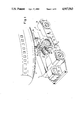
- FIG. 1 is a fragmentary, perspective view of a towing vehicle constructed in accordance with the present invention and pulling an aircraft
- FIG. 2 is a schematic side elevational view, in section, through the nose wheel lifting and securing mechanism of the vehicle shown in FIG. 1;
- FIG. 3 is a plan view of the lifting and securing mechanism shown in FIG. 2;
- FIG. 4 is a fragmentary, elevational perspective view of the lifting mechanism shown in FIG. 2 and illustrates associated mounting supports and power drives:
- FIG. 5 is a multi-phase illustration of the lifting and securing mechanism s it engages and secures an aircraft nose wheel having a relatively small diameter
- FIG. 6 is a multi-phase illustration, similar to FIG. 5, of a lifting and securing mechanism as it engages and secures an aircraft nose wheel having a relatively large diameter:
- FIG. 7 is a graph illustrating as a function of elapsed time the pressure gradient within a hydraulic cylinder of the lifting mechanism as it engages a nose wheel and
- FIG. 8 is a simplified diagram of the hydraulic and electrical circuits for the lifting and securing mechanism of the present invention.
- FIG. 1 schematically shows a towing vehicle 1 hauling an aircraft 2.
- Towing vehicle 1 has a bifurcated chassis defined by two side arms 1a, 1b which form between them a rearwardly opening well or recess 3.
- the aircraft nose wheels 4 are now engaged by the lifting and securing mechanism of the present invention, lifted off the ground, and secured or locked to the towing vehicle.
- FIG. 1 shows a simplified embodiment of the lifting and securing mechanism in side perspective with side arm 1a broken partially away to provide a better view of the mechanism.
- the mechanism has the following main components:
- An abutment 6 pivotally mounted on a longitudinally oriented shaft 5.
- the abutment includes a vertically oriented, rearwardly facing stop plate 7 for the nose wheels 4.
- a ramp 10 for supporting nose wheels 4 which is connected to abutment 6 and which is pivotable about a horizontal axis.
- Each holder engages a nose wheel 4, generally from the front and above.
- a hydraulic actuator forces each holder generally downwardly against the periphery of the associates wheel.
- a lifting mechanism or lifter 40 that can be moved generally forwardly (to the left as seen in FIG. 1) into engagement with an aft portion of each wheel to push the wheel up ramp 10, and then forcing the wheel with a predetermined force against stop plate 7.
- FIG. 1 also shows equipment that forms part of the nose wheel undercarriage and is located immediately above the nose wheels 4 such as a hydraulic steering cylinder 8 and a landing gear door 9. It is absolutely essential that the nose wheel lifting and securing mechanism be constructed so that no part of the aircraft, including the above-mentioned components can be damaged even in the event of a malfunction or mishandling of the towing vehicle and/or its nose wheel lifting and securing mechanism.
- FIG. 2 shows in a side elevational view the part of the lifting mechanism affixed to the right side arm 1b.
- FIG. 3 is a plan view of the entire lifting and securing mechanism.
- Abutment 6 and its associated stop plate 7 are pivotable about a longitudinally extending horizontal shaft 5 mounted to a cross beam 1c of the towing vehicle.
- Ramp 10 is pivotable about transverse, horizontal shaft 11 and it is disposed aft (to the right as seen in FIG. 2) of abutment 6.
- Ramp 10 has a shovel-like, upwardly concave (on the side facing the nose wheel) or angled profile. It includes a front section (immediately to the left of shaft 11 in FIG. 2) which is steeper or more vertically inclined than the rear section.
- the ramp may be fitted with a centering rib 12 that extends in between the nose wheels to assist in aligning the nose wheel undercarriage with the center of the towing vehicle aircraft.
- FIG. 2 shows ramp 10 in its rest position in which the ramp's lower (aft) surface is substantially parallel to runway 13, and does not extend below the chassis of the towing vehicle so as to not reduce its ground clearance.
- ramp 10 is tilted in a clockwise direction out of its rest position shown in FIG. 2 into a wheel receiving position in which its aft edge is proximate to, e.g., spaced only a short distance above runway surface 13.
- the nose wheels ride up on ramp 10 it is tilted in a counterclockwise direction past its rest position shown in FIG. 2, to a holding position in which the ramp fully supports the nose wheel undercarriage.
- Each holder 20 includes at its free end a roller 21 supported by a pair of parallel links 22 pivotally mounted to a carrier 24.
- the carrier 24 in turn is supported by two guide arms 27 which are pivotally attached to a forwardly projecting bracket 6a of abutment 6.
- a hydraulic hold-down actuator 28 is pivotably attached to the vehicle chassis and, upon activation, exerts a downward force onto carrier 24.
- the upper portion of carrier 24 forms a stop surface 26 which limits the movement path of holder 20 supported by links 22.
- the entire mechanism is constructed so that it moves, when a nose wheel riding up on ramp 10 from its rearward most position, as shown in FIG. 2, applies a force against the holder, along an initial arc A to position 20' as guided by links 22. At this point, holder 20 abuts contact surface 26 of carrier 24.
- the holder 20, together with carrier 24 move along a second arc A' into their uppermost position 20" under the guidance of arms 27.
- the above described components of this mechanism are dimensioned and arranged so that nose wheels of the relatively larger aircraft types can be engaged.
- the Boeing 757 exhibits the smallest nose wheel diameter, i.e. 31 inches (79 cm) while the Boeing 747 has the largest nose wheel diameter of about 49 inches (124 cm), with other conventional commercial aircraft, e.g. the Boeing 767, DC 8, DC 10, the Airbus A-300 and A310 having nose wheel diameters between these extremes.
- roller 21 of holder 20 is located 62-79 cm above the surface of runway 13, which is less than the diameter of the smallest nose wheel, but higher than half the diameter of the largest nose wheel of the above mentioned aircraft types.
- holder 20 is located above the aft edge of ramp 10, and to the rear of ramp pivot shaft 11.
- holder 20 When so arranged, holder 20 contacts the forward upper quadrant of the nose wheel's periphery, irrespective of the wheel diameter when the wheels are first engaged by the ramp. It is then forced upwardly by the wheels as they travel up ramp 10. At no point prior to or during the engaging phase does the holder extend above the uppermost extent of the nose wheel periphery where it might cause damage to the steering cylinder, the nose wheel door or other components of the nose wheel under carriage.
- a lifting mechanism or lifter 40 Directly opposite the holder 20, ramp 10 and stop plate 7 is a lifting mechanism or lifter 40.
- the lifter is defined by two sets of rollers, a movable lower segment and a fixed upper segment which are described in further detail below.
- Each lifter 40 is mounted to a rocker arm 42 and can be pivoted about a substantially vertical axis 41.
- the rocker arm 42 in turn is journaled in a horizontally oriented bearing 43 mounted to a corresponding side arm, e.g. arm 1b of the vehicle chassis.
- a hydraulic actuator 44 is provided for moving lifter 40 from its rearwardmost position, shown in FIG. 2, forwardly toward ramp 10 and stop plate 7 to thereby push an aircraft nose wheel up the ramp 10.
- Each lifter 40 on the associated rocker arm 42 can also be tilted about a generally upright axis 45.
- the upper ends of the guides are connected to link 47 while their lower ends are attached to bearings 48a, 49a mounted to side arm 1b of the vehicle chassis.
- a hydraulic motor 57 is mounted to rocker arm 42 for pivoting lifter 40 about axis 41 into its non-operating or retracted position in which the lifter is proximate, i.e., effectively parallel to the wall of chassis side arm 1b.
- FIG. 3 where the left hand lifter 40 (in the direction of forward movement of the vehicle, i.e., to the left as shown in FIG. 3) mounted to the left side arm 1a is shown in its retracted position.
- both lifting mechanisms are in their retracted positions so that the nose wheel undercarriage can pass uninhibited into chassis recess 3. Only thereafter are the lifters pivoted into their operative positions to engage each nose wheel from behind.
- Rocker arm 42 is pivotable about a horizontal axis defined by a bearing 43 which is secured to the vehicle chassis.
- the rocker arm includes a sleeve bearing 52 which journals a vertical shaft 53 of a support 54 for the lifter so that the shaft can pivot about the vertical axis 41.
- the support rotatably mounts a further, horizontal shaft 45 to which lifter 40 is immovably keyed with radial teeth 45a.
- Support 54 includes a cutout 54a, on the side of the bearing for shaft 45 opposite lifter 40, into which a bifurcated end 45b of shaft 45 extends.
- This bifurcated end of the shaft is pivotally coupled to a lug 46b of control arm 46 with a pivot pin 55 that is coaxial with the vertical axis 41 of sleeve bearing 52,
- control arm 46 rotates with shaft 45 about the horizontal axis of the latter so that it can be employed for controlling pivotal movements of shaft 45 with respect to support 54 for lifter 40 when hydraulic actuator 44 pivots rocker arm 42, together with lifter 40 about the axis of bearing 43.
- the pivotable connection between control arm 46 and shaft 45 enables support 54 and lifter 40 carried thereby to pivot about axis 41 of sleeve bearing 52 so that the lifter can be pivotally moved into its retracted position 40', illustrated by broken lines in FIG. 4.
- This pivotal motion is generated by a hydraulic motor 57, mounted to rocker arm 42, which drives a crank arm 58 having a free end pivotally connected with a pin 58a to a push bar 59.
- the push bar in turn is pivotably attached to support 54 with another pin 61.
- crank arm 58 abuts a detent 42a on rocker arm 42 to prevent the clockwise rotation of the carrier about axis 41 past its operating position.
- Push bar 59 extends from pivot 58a to pivot 61, on the right side of hydraulic motors 57 as seen in FIG. 4, when support 54 and the lifter are in their operating position.
- crank arm 58 must pivot through more than 180 degrees to pivot support 54 through 90 degrees and thereby return lifter 40 to its retracted position. In this position pivot 58a at the free end of the crank arm has substantially moved to where pivot 61 on support 54 is shown in FIG. 4.
- Vertical axis 41 has a slight forward inclination so that lifter 40 rises somewhat as it pivots into its retracted position. This prevents the lower edge of lifter 40 from reducing the vehicle's ground clearance, In its operating position, however, the lifter may without adverse effects extend below the underside of the vehicle chassis prior to and during the engagement of the nose wheel.
- FIG. 5 schematically shows various operating positions of the lifter and the holding mechanism as a nose wheel is being engaged and secured.
- the drawing illustrates a nose wheel having a diameter at the low end of the range of nose wheel diameters of common commercial aircraft for which the towing vehicle is intended.
- the range of diameters is from about 30 inches (75 cm) to about 50 inches (125 cm) and ranges from the Boeing 757 (nose wheel diameter 31") at the lower end of the spectrum to the Boeing 747 (nose wheel diameter 49”) at the higher end.
- the lifter and holding mechanism must be constructed to receive all nose wheels falling in this size range effectively and without risk of damage. Once a wheel is received, it must further be firmly secured to prevent the possibility of an accidental release of the wheel.
- lifter 40 In the operation lifter 40 is initially in its retracted position.
- the towing vehicle is maneuvered backwards towards the parked aircraft until the nose wheel enters the U-shaped recess of the vehicle chassis and contacts the aft edge of ramp 10.
- the impact of the wheel against ramp 10 tilts the ramp downwardly into position 10", shown in solid lines in FIG. 5.
- Ramp 10 thereby activates a limit switch S2 which generates a signal that is used to disengage the towing vehicle's drive, at least for reverse operation to prevent the vehicle from backing into and possibly damaging nose wheel 4.
- the signal from switch S2 activates the power drives 57,44 for lifter 40.
- the operator can then engage the power drives by means of a control lever.
- limit switch S2 has not been activated as a result of contact between nose wheel 4 and ramp 10
- the power drives are inoperative to prevent the unintended activation of the lifter.
- hydraulic motor 57 When the power drives are activated, hydraulic motor 57 first pivots each lifter 40 from its retracted into its operating position. Each hydraulic actuator 44 is then energized with hydraulic fluid to force the associated piston rod outward. In this manner, lifter 40 and angularly fixed control arm 46 are advanced from their starting position, indicated by broken lines in FIG. 5, to an intermediate position 40", 46" shown in solid lines, in which the rollers of lifter 40 abut nose wheel 4 while the lower, tiltably mounted roller segment 40a of the lifter pivotally adjusts itself to the periphery of the nose wheel. As the piston rod continues to move out of hydraulic actuator 44, lifter 40 pushes nose wheel 4 onto and up ramp 10.
- the nose wheel also contacts holder 20 and, as the wheel rides up ramp 10, the holder, guided by links 22, moves along arcuate path A.
- the point of contact between the holder and the nose wheel will consistently be in the forward upper quadrant of the nose wheel's periphery, typically between about 30-60 degrees from the wheel's apex.
- holder 20 will have engaged contact surface 26 of carrier 24, hence pushing the carrier, as guided by arms 27, upward and simultaneously withdrawing the piston rod of the hydraulic hold-down actuator 28 out of the associated hydraulic cylinder.
- control arm 46 causes lifter 40 to initially tilt slightly rearwardly, as it pivots forwardly, so that its lower segment 40a reaches or extends as far as possible beneath the nose wheel.
- At the terminal portion of the forward pivot lifter 40 tilts sharply forward so that its rigid upper segment abuts the nose wheel periphery, or is at least in close proximity to the wheel where it functions, together with holder 20, as a barrier which secures the nose wheel in position and prevents it from further moving in an upward direction.
- a limit switch S1 is activated. It generates a signal that is used to apply hydraulic fluid of a controlled pressure to hydraulic actuators 44 and 28 (cf. FIG.
- Hydraulic actuator 28 is locked in its set position by sealing the pressurized hydraulic fluid in its cylinder so that it continues to act on its piston.
- the sealed in pressure in actuator 28 automatically lowers the holder. This, however, leads to an immediate pressure reduction in the actuator which is detected by a pressure sensor and triggers an alarm signal warning the driver to stop the towing vehicle. Further, as the holder moves towards the axis of the deflating nose wheel, a piston rod clamp 28a of hydraulic actuator 28 is released to arrest the further retraction of the piston rod after a piston movement of only a few mm. Thus, the nose wheel remains firmly secured despite the malfunction.
- FIG. 6 shows, similar to FIG. 5, the various positions of a nose wheel that is being engaged and secured but which has a large diameter wheel with respect to the range of nose wheels cited above, e.g. the nose wheel of a B 747 aircraft having a wheel diameter of about 49".
- the nose wheel shown in solid lines is positioned on the tip of ramp 10 after it tilted the latter downwardly, Holder 20 touches the nose wheel periphery, while lifter 40 has made peripheral contact with the nose wheel after having been pivoted forward from its retracted position but before it has been significantly tilted rearwardly by control arm 46.
- the lifter continues to advance forward, pushing the nose wheel 4 onto ramp 10, it is tilted increasingly rearwardly, i.e. in a clockwise direction as seen in FIG.
- FIGS. 5 and 6 were drawn as if nose wheel 4 together with the entire aircraft were pulled forward, In fact, however, the aircraft remains stationary during the entire receiving and loading operation while the forward pressure exerted by lifting mechanism 40 against nose wheel 4 causes the towing vehicle to move backwards (i.e. to the right as seen in FIGS. 5 and 6). sliding ramp 10 underneath the nose wheel and thereby pushing the nose wheel upwardly.
- any attempt to illustrate the reverse motion of the tow vehicle would render the drawing unnecessarily complex and unclear. Instead the relative positions of components shown in FIGS. 5 and 6 have been drawn as if the towing vehicle remained stationary.
- lifter 40 When the nose wheel is first engaged, lifter 40 bears substantially the entire dead weight resting on the nose wheel and, in addition, it must generate the necessary force to lift the nose wheel off the ground. It is therefore essential that hydraulic actuator 44 generates a very large force which is achieved by applying a correspondingly large hydraulic pressure to the actuator. As the engaging operation proceeds, however, in increasing proportion of the nose wheel dead weight is transferred to ramp 10, especially after the latter has tilted about its pivot axis into its raised position. The force that must be generated by lifter 40 and the magnitude of hydraulic pressure in actuator 44 decreases accordingly.
- FIG. 7 illustrates schematically the pressure gradient P prevailing in hydraulic actuator 44 as a function of the distance traveled by lifter 40.
- Upper curve P' shows the pressure gradient for an aircraft with a large nose wheel diameter, as shown in FIG. 6, supporting a correspondingly greater dead weight.
- Lower curve P" shows the pressure gradient for an aircraft with a relatively smaller nose wheel diameter, as shown in FIG. 5, supporting comparatively lesser dead weight.
- the two curves of FIG. 7 are merely approximations and it should be understood that no direct correlation necessarily exists between a given aircraft's dead weight and the nose wheel diameter.
- curves P' and P" is also a function of the relative dimensions and geometry of the components of the steering linkage which controls the movement of lifter 40. These are selected so that the force generated on lifting mechanism 40 during the final stages of the engaging operation, even for wheels subjected to the largest dead weight, and therewith the magnitude of the hydraulic pressure in actuator 44, is lower than the predetermined wheel clamping force, and the clamping pressure Pe required to achieve this force that is to be exerted on the nose wheel when it is in its secured position. This is a necessary prerequisite that, in accordance with the present invention, the pressure in hydraulic actuator 44 can be increased to the clamping pressure Pe following the nose wheel engaging operation.
- the magnitude of the clamping pressure is independent of the nose wheel diameter and it is selected so that it is sufficient to firmly secure the nose wheel in position and minimize vibrations and relative nose wheel movements which are necessarily encountered during towing as a result of the elasticity of the tires.
- the clamping pressure Pe applied to the actuator is selected so that the clamping force acting on the nose wheel cannot damage it or flatten the tire against the rim.
- the clamping pressure Pe should be selected so that clamping force of about 2 tons is exerted on the nose wheel.
- FIG. 8 is a simplified diagram of the electrical and hydraulic circuits employed by the nose wheel lifting and securing mechanisms of the present invention. Hydraulic conduits are shown in dark, solid lines, hydraulic control lines are shown in dot-dash lines, and the circuitry for electric signals are shown in broken lines. Actuator 28 and 44 and motor 57 for the lifter and the holder are all hydraulically operated. Pressurized hydraulic fluid flows from a source that includes a feed reservoir 68, a pump 63 and, if needed, a pressure tank 65, into a pressure line 67.
- the driver of the towing vehicle can manually operate a lever 73 to electrically open a valve 75 for directing pressurized hydraulic fluid to the hydraulic motors 57 and hydraulic actuators 44.
- the valve can only be engaged after the towing vehicle has properly abutted the nose wheel and tipped ramp 10 downwardly, thereby activating limit switch S2 enabling valve 75 via a relay 81.
- valve 75 permits the flow of pressurized hydraulic fluid through hydraulic line 77 to hydraulic motors 57.
- the motors then pivot the lifters through 90 degrees into their operating positions (cf. FIG. 4). Spent hydraulic fluid from motors 57 flows through a check valve 85 and a hydraulic line 79 into return line 69.
- the pressure in hydraulic motors 57 is less than the threshold pressure of a pressure release valve 83 so that the valve prevents the flow of hydraulic fluid to the hydraulic actuator 44.
- the pressure in line 77 increases which opens pressure valve 83. This allows pressurized hydraulic fluid to enter the cylinders of hydraulic actuators 44, forcing the piston rods outwardly and pivoting lifters 40 forward about bearings 43 until the rollers or the lifters contact the nose wheels.
- the hydraulic medium on the other sides of the pistons can exit from actuators 44 into hydraulic line 79.
- switch unit 91 When signals are emitted by both switches S1 and 89, switch unit 91 closes valve 75, thereby completing the engaging and nose wheel lifting operation.
- a check valve 93 in fluid communication with the cylinders of hydraulic actuators 44 causes the retention of the pressure in the cylinder which prevailed when pressure switch 89 was activated, thereby setting the clamping pressure Pe.
- each hydraulic actuator 44 is held open, i.e., it is deactivated by the pressure in hydraulic control conduit 97.
- piston rod clamps 44a are released by opening control valve 98 to depressurize control conduit 97.
- the piston rods of hydraulic actuators 44 are thereby clamped or locked in place and nose wheel 4 remains firmly secured, even in the event of a pressure loss in the hydraulic system.
- hydraulic actuators 28 are most of the time pressureless, allowing holders 20 to move freely with the nose wheel.
- pressurized hydraulic fluid from a pressure relief valve 62 flows via this control valve 76, a second relief valve 64 and a check valve 66 to the piston rod side of the cylinder of actuator 28,
- the second relief valve 64 restricts the level of pressure flow to, for example, a very low 6 bars, to only slightly prestress the holder 20.
- Lifter 40 can readily overcome the force generated thereby.
- ramp 10 has activated limit switch S1, and the increased pressure in actuator 44 triggers pressure switch 89, switch unit 91 generates a signal that reverses the setting of control valve 76.
- Pressurized fluid now flows through line 67 past the first relief valve 62 and a check valve 72 into hydraulic actuator 28.
- the hydraulic pressure at relief valve 62 is set to equal the clamping pressure Pe. e.g. 85 bars.
- the holders in turn are now subjected to a clamping force of a predetermined magnitude determined by the magnitude of pressure Pe discussed above.
- a pressure switch 82 set for a threshold pressure which equals pressure Pe reverses a shutoff valve 84 to thereby retain the hydraulic fluid in actuator 28 at pressure Pe. This completes the securing phase.
- Each actuator 28 is fitted with a well known piston rod clamp 28a which is disengaged by pressurized hydraulic fluid from control line 97 and which is activated at the completion of each nose wheel engaging operation by operating control valve 98.
- the piston rod clamps 28a oppose any further extension of the piston rods although the clamps do not oppose the further retraction of piston rods. If, when the piston rod clamps 28a are activated, the grip on nose wheel slackens, for example as a result a sudden loss of tire pressure, the holders move slightly, which results in an immediate, sharp pressure drop in the actuators 28. This pressure drop is sensed by a sensor 94 which signals a malfunction or generates an alarm signal. The signal warns the driver of the towing vehicle that the nose wheel is no longer properly secured and that it is unsafe to continue towing.
Applications Claiming Priority (2)
| Application Number | Priority Date | Filing Date | Title |
|---|---|---|---|
| DE3732644A DE3732644C1 (de) | 1987-09-28 | 1987-09-28 | Schleppfahrzeug fuer Flugzeuge - Definierte Verzurrkraefte |
| DE3732644 | 1987-09-28 |
Publications (1)
| Publication Number | Publication Date |
|---|---|
| US4917563A true US4917563A (en) | 1990-04-17 |
Family
ID=6337049
Family Applications (1)
| Application Number | Title | Priority Date | Filing Date |
|---|---|---|---|
| US07/250,286 Expired - Fee Related US4917563A (en) | 1987-09-28 | 1988-09-28 | Aircraft towing vehicle having a mechanism for substantially preventing relative aircraft wheel movements |
Country Status (6)
| Country | Link |
|---|---|
| US (1) | US4917563A (es) |
| EP (1) | EP0309760B1 (es) |
| JP (1) | JPH01103597A (es) |
| AT (1) | ATE79810T1 (es) |
| DE (1) | DE3732644C1 (es) |
| ES (1) | ES2034078T3 (es) |
Cited By (19)
| Publication number | Priority date | Publication date | Assignee | Title |
|---|---|---|---|---|
| DE4129407A1 (de) * | 1991-09-04 | 1993-03-11 | Gutehoffnungshuette Man | Schleppfahrzeug ohne schleppstange zum bugsieren von flugzeugen |
| US5308212A (en) * | 1991-01-31 | 1994-05-03 | Krauss Maffei Aktiengesellschaft | Aircraft towing vehicle |
| US5314287A (en) * | 1989-05-26 | 1994-05-24 | Schopf Maschinenbau Gmbh | Process and device for attaching an aircraft nose landing gear to an aircraft tractor |
| US5722810A (en) * | 1995-11-07 | 1998-03-03 | Jerr-Dan Corporation | Over-center locking mechanism for tow truck wheel-lift or the like |
| US5860785A (en) * | 1994-05-02 | 1999-01-19 | Goldhofer Fahrzeugwerk Gmbh & Co. | Towing vehicle for maneuvering aircraft |
| US6315515B1 (en) | 1995-11-07 | 2001-11-13 | Jerr-Dan Corporation | Over-center towing locking mechanism for tow truck wheel lift or the like |
| EP1242281A1 (en) * | 1999-12-14 | 2002-09-25 | Bliss-Fox Ground Support Equipment Pty Ltd | Tug for aircraft |
| US20080083851A1 (en) * | 2006-09-28 | 2008-04-10 | Arie Perry | System and method for transferring airplanes |
| US20080099600A1 (en) * | 2006-09-28 | 2008-05-01 | Israel Aircraft Industries Ltd. | System and method for transferring airplanes |
| US20100096494A1 (en) * | 2007-05-16 | 2010-04-22 | Israel Aerospace Industries Ltd. | System and method for transferring airplanes |
| US20100140392A1 (en) * | 2006-09-28 | 2010-06-10 | Israel Aerospace Industries Ltd. | Towbarless airplane tug |
| US20110224845A1 (en) * | 2008-11-25 | 2011-09-15 | Israel Aerospace Industries Ltd. | Towbarless airplane tug |
| US8640804B2 (en) | 2010-06-09 | 2014-02-04 | Israel Aerospace Industries Ltd. | Vehicle for towing an airplane |
| US8825338B2 (en) | 2010-05-30 | 2014-09-02 | Israel Aerospace Industries Ltd. | Controller for a drive system |
| US8935049B2 (en) | 2010-02-16 | 2015-01-13 | Israel Aerospace Industries Ltd. | Plane tractor |
| US9090358B2 (en) | 2006-09-28 | 2015-07-28 | Israel Aerospace Industries Ltd. | System and method for transferring airplanes |
| WO2017085517A1 (en) * | 2015-11-19 | 2017-05-26 | Textron Ground Support Equipment Uk Limited | Aircraft engagement mechanism for aircraft mover |
| US11142341B2 (en) * | 2016-03-18 | 2021-10-12 | Goldhofer Ag | Towing vehicle |
| CN113928570A (zh) * | 2021-11-19 | 2022-01-14 | 中国科学院长春光学精密机械与物理研究所 | 航天装置的锁紧机构 |
Families Citing this family (9)
| Publication number | Priority date | Publication date | Assignee | Title |
|---|---|---|---|---|
| DE3801855A1 (de) * | 1987-01-23 | 1988-09-08 | Heck Gert | Schleppfahrzeug zum manoevrieren von flugzeugen |
| DE3901650C2 (de) * | 1989-01-20 | 1994-06-01 | Goldhofer Fahrzeugwerk | Schleppfahrzeug zum Manövrieren von Flugzeugen |
| DE58903892D1 (de) * | 1989-04-28 | 1993-04-29 | Gutehoffnungshuette Man | Flugzeug-schlepper ohne schleppstange (schwenkteleskop). |
| EP0394534B1 (de) * | 1989-04-28 | 1993-08-18 | MAN Gutehoffnungshütte Aktiengesellschaft | Flugzeug-Schlepper ohne Schleppstange (Drehschaufel) |
| DE4009419C2 (de) * | 1990-03-23 | 1997-09-11 | Krauss Maffei Ag | Bugfahrwerk-Einspannvorrichtung für ein Flugzeug-Schleppfahrzeug |
| DE4024894C2 (de) * | 1990-08-06 | 1997-05-22 | Krauss Maffei Ag | Schleppfahrzeug für Flugzeuge |
| IT1257366B (it) * | 1992-08-03 | 1996-01-15 | Fresia Spa | Trattore per traino di aeromobili. |
| IT1263472B (it) * | 1993-09-20 | 1996-08-05 | Fresia Spa | Trattore per il traino di aeromobile attraverso le sue ruote centrali anteriori sterzanti,con sollevamento o meno delle stesse. |
| DE19942261A1 (de) * | 1999-09-04 | 2001-03-22 | Ghh Fahrzeuge Gmbh | Schleppfahrzeug ohne Schleppstange zum Bugsieren von Flugzeugen |
Citations (11)
| Publication number | Priority date | Publication date | Assignee | Title |
|---|---|---|---|---|
| US3049253A (en) * | 1959-06-09 | 1962-08-14 | Yuba Cons Ind Inc | Airplane tow tractor |
| US3075599A (en) * | 1959-03-02 | 1963-01-29 | American Coleman Company | Aircraft tug |
| US3586187A (en) * | 1969-03-06 | 1971-06-22 | Preston M Wright | Aircraft towing apparatus |
| DE2812434A1 (de) * | 1977-04-07 | 1978-10-12 | Secmafer Buchelay Sa | Zugmaschine zum bewegen von grossraumflugzeugen auf flugplaetzen |
| US4375244A (en) * | 1979-04-18 | 1983-03-01 | Sovam | Hauling vehicle for large aircraft |
| WO1985000790A1 (en) * | 1983-08-18 | 1985-02-28 | Bruun, Svend, Aage, Johan | Method and tractor for towing aeroplanes |
| WO1985001265A1 (en) * | 1983-09-13 | 1985-03-28 | Matti Sinkkonen | Apparatus to move wheeled vehicle |
| US4632625A (en) * | 1983-05-18 | 1986-12-30 | Krauss-Maffei Aktiengesellschaft | Aircraft-towing tractor |
| US4655670A (en) * | 1983-11-17 | 1987-04-07 | Hoegberg Kjell T | Transportation device |
| DE3534045A1 (de) * | 1985-09-24 | 1987-04-16 | Krauss Maffei Ag | Schleppfahrzeug zum manoevrieren von flugzeugen |
| US4810157A (en) * | 1986-05-17 | 1989-03-07 | Man Gutehoffnungshutte Gmbh | Tractor for maneuvering an airplane without a tow bar |
Family Cites Families (2)
| Publication number | Priority date | Publication date | Assignee | Title |
|---|---|---|---|---|
| DE3327629A1 (de) * | 1983-07-30 | 1985-02-07 | Krauss-Maffei AG, 8000 München | Rangierfahrzeug |
| DE3521429A1 (de) * | 1985-06-14 | 1986-12-18 | Krauss-Maffei AG, 8000 München | Rangierfahrzeug zum manoevrieren von flugzeugen |
-
1987
- 1987-09-28 DE DE3732644A patent/DE3732644C1/de not_active Expired
-
1988
- 1988-09-02 AT AT88114319T patent/ATE79810T1/de not_active IP Right Cessation
- 1988-09-02 ES ES198888114319T patent/ES2034078T3/es not_active Expired - Lifetime
- 1988-09-02 EP EP88114319A patent/EP0309760B1/de not_active Expired - Lifetime
- 1988-09-20 JP JP63233864A patent/JPH01103597A/ja active Pending
- 1988-09-28 US US07/250,286 patent/US4917563A/en not_active Expired - Fee Related
Patent Citations (12)
| Publication number | Priority date | Publication date | Assignee | Title |
|---|---|---|---|---|
| US3075599A (en) * | 1959-03-02 | 1963-01-29 | American Coleman Company | Aircraft tug |
| US3049253A (en) * | 1959-06-09 | 1962-08-14 | Yuba Cons Ind Inc | Airplane tow tractor |
| US3586187A (en) * | 1969-03-06 | 1971-06-22 | Preston M Wright | Aircraft towing apparatus |
| DE2812434A1 (de) * | 1977-04-07 | 1978-10-12 | Secmafer Buchelay Sa | Zugmaschine zum bewegen von grossraumflugzeugen auf flugplaetzen |
| US4225279A (en) * | 1977-04-07 | 1980-09-30 | Societe Anonyme Secmafer | Airport towing vehicle for handling large transport aircrafts |
| US4375244A (en) * | 1979-04-18 | 1983-03-01 | Sovam | Hauling vehicle for large aircraft |
| US4632625A (en) * | 1983-05-18 | 1986-12-30 | Krauss-Maffei Aktiengesellschaft | Aircraft-towing tractor |
| WO1985000790A1 (en) * | 1983-08-18 | 1985-02-28 | Bruun, Svend, Aage, Johan | Method and tractor for towing aeroplanes |
| WO1985001265A1 (en) * | 1983-09-13 | 1985-03-28 | Matti Sinkkonen | Apparatus to move wheeled vehicle |
| US4655670A (en) * | 1983-11-17 | 1987-04-07 | Hoegberg Kjell T | Transportation device |
| DE3534045A1 (de) * | 1985-09-24 | 1987-04-16 | Krauss Maffei Ag | Schleppfahrzeug zum manoevrieren von flugzeugen |
| US4810157A (en) * | 1986-05-17 | 1989-03-07 | Man Gutehoffnungshutte Gmbh | Tractor for maneuvering an airplane without a tow bar |
Non-Patent Citations (2)
| Title |
|---|
| Lastanto Omnibus, Dec. 1985, pp. 40 41, article entitled Boden Personal . * |
| Lastanto Omnibus, Dec. 1985, pp. 40-41, article entitled "Boden-Personal". |
Cited By (33)
| Publication number | Priority date | Publication date | Assignee | Title |
|---|---|---|---|---|
| US5314287A (en) * | 1989-05-26 | 1994-05-24 | Schopf Maschinenbau Gmbh | Process and device for attaching an aircraft nose landing gear to an aircraft tractor |
| US5308212A (en) * | 1991-01-31 | 1994-05-03 | Krauss Maffei Aktiengesellschaft | Aircraft towing vehicle |
| DE4129407A1 (de) * | 1991-09-04 | 1993-03-11 | Gutehoffnungshuette Man | Schleppfahrzeug ohne schleppstange zum bugsieren von flugzeugen |
| US5860785A (en) * | 1994-05-02 | 1999-01-19 | Goldhofer Fahrzeugwerk Gmbh & Co. | Towing vehicle for maneuvering aircraft |
| US5722810A (en) * | 1995-11-07 | 1998-03-03 | Jerr-Dan Corporation | Over-center locking mechanism for tow truck wheel-lift or the like |
| US6315515B1 (en) | 1995-11-07 | 2001-11-13 | Jerr-Dan Corporation | Over-center towing locking mechanism for tow truck wheel lift or the like |
| EP1242281A1 (en) * | 1999-12-14 | 2002-09-25 | Bliss-Fox Ground Support Equipment Pty Ltd | Tug for aircraft |
| US20030095854A1 (en) * | 1999-12-14 | 2003-05-22 | Rene Abela | Tug for aircraft |
| EP1242281A4 (en) * | 1999-12-14 | 2006-04-05 | Bliss Fox Ground Support Equip | AIR TRACTOR |
| US8245980B2 (en) | 2006-09-28 | 2012-08-21 | Israel Aerospace Industries Ltd. | System and method for transferring airplanes |
| US9022317B2 (en) | 2006-09-28 | 2015-05-05 | Israel Aerospace Industries Ltd. | Towbarless airplane tug |
| US20100140392A1 (en) * | 2006-09-28 | 2010-06-10 | Israel Aerospace Industries Ltd. | Towbarless airplane tug |
| US7975959B2 (en) | 2006-09-28 | 2011-07-12 | Israel Aerospace Industries Ltd. | System and method for transferring airplanes |
| US20080099600A1 (en) * | 2006-09-28 | 2008-05-01 | Israel Aircraft Industries Ltd. | System and method for transferring airplanes |
| US20080083851A1 (en) * | 2006-09-28 | 2008-04-10 | Arie Perry | System and method for transferring airplanes |
| US9403604B2 (en) | 2006-09-28 | 2016-08-02 | Israel Aerospace Industries Ltd. | System and method for transferring airplanes |
| US8544792B2 (en) | 2006-09-28 | 2013-10-01 | Israel Aerospace Industries Ltd. | Towbarless airplane tug |
| US9090358B2 (en) | 2006-09-28 | 2015-07-28 | Israel Aerospace Industries Ltd. | System and method for transferring airplanes |
| WO2008139440A2 (en) | 2007-05-16 | 2008-11-20 | Israel Aerospace Industries Ltd. | Towbarless airplane tug |
| US20100096494A1 (en) * | 2007-05-16 | 2010-04-22 | Israel Aerospace Industries Ltd. | System and method for transferring airplanes |
| US9199745B2 (en) | 2007-05-16 | 2015-12-01 | Israel Aerospace Industries Ltd. | System and method for transferring airplanes |
| US20110224845A1 (en) * | 2008-11-25 | 2011-09-15 | Israel Aerospace Industries Ltd. | Towbarless airplane tug |
| US8774983B2 (en) | 2008-11-25 | 2014-07-08 | Israel Aerospace Industries Ltd. | Towbarless airplane tug |
| US8515594B2 (en) | 2008-11-25 | 2013-08-20 | Israel Aerospace Industries Ltd. | Towbarless airplane tug |
| US8935049B2 (en) | 2010-02-16 | 2015-01-13 | Israel Aerospace Industries Ltd. | Plane tractor |
| US9085374B2 (en) | 2010-02-16 | 2015-07-21 | Israel Aerospace Industries Ltd. | Plane tractor |
| US9187185B2 (en) | 2010-02-16 | 2015-11-17 | Israel Aerospace Industries Ltd. | Plane tractor |
| US8825338B2 (en) | 2010-05-30 | 2014-09-02 | Israel Aerospace Industries Ltd. | Controller for a drive system |
| US8640804B2 (en) | 2010-06-09 | 2014-02-04 | Israel Aerospace Industries Ltd. | Vehicle for towing an airplane |
| WO2017085517A1 (en) * | 2015-11-19 | 2017-05-26 | Textron Ground Support Equipment Uk Limited | Aircraft engagement mechanism for aircraft mover |
| US11142341B2 (en) * | 2016-03-18 | 2021-10-12 | Goldhofer Ag | Towing vehicle |
| CN113928570A (zh) * | 2021-11-19 | 2022-01-14 | 中国科学院长春光学精密机械与物理研究所 | 航天装置的锁紧机构 |
| CN113928570B (zh) * | 2021-11-19 | 2023-12-01 | 中国科学院长春光学精密机械与物理研究所 | 航天装置的锁紧机构 |
Also Published As
| Publication number | Publication date |
|---|---|
| ATE79810T1 (de) | 1992-09-15 |
| EP0309760A2 (de) | 1989-04-05 |
| ES2034078T3 (es) | 1993-04-01 |
| EP0309760B1 (de) | 1992-08-26 |
| DE3732644C1 (de) | 1988-09-15 |
| EP0309760A3 (en) | 1990-04-25 |
| JPH01103597A (ja) | 1989-04-20 |
Similar Documents
| Publication | Publication Date | Title |
|---|---|---|
| US4917563A (en) | Aircraft towing vehicle having a mechanism for substantially preventing relative aircraft wheel movements | |
| US4911604A (en) | Aircraft towing vehicle having steered nose wheel lifting mechanism | |
| US4917564A (en) | Hold-down system for an aircraft towing vehicle | |
| US4911603A (en) | Aircraft towing vehicle having swiveled nose wheel lifter | |
| EP0357087B1 (en) | Truck supporting device | |
| US3687321A (en) | Load carrying vehicle | |
| CA2512909C (en) | Chocking apparatus | |
| US4836734A (en) | Ground vehicle for maneuvering aircraft | |
| KR20100134988A (ko) | 2륜차의 안전 주행 보조용의 보조 바퀴를 구비한 자동 모터 구동 스탠드 장치 | |
| US4480867A (en) | Swivel chair system | |
| US4576245A (en) | Self-propelled pedestrian-controlled tractor for towing helicopters | |
| JPH04504391A (ja) | 航空機を操作するための牽引車輛 | |
| US3820670A (en) | Automobile shipping container unloader | |
| JPH05124798A (ja) | 荷物運搬用車輌 | |
| CA1308222C (en) | Truck supporting device | |
| JP5502317B2 (ja) | 軌道走行車両の走行制御装置 | |
| CN207403736U (zh) | 一种自运行无人驾驶轨道运输装置 | |
| JP6551284B2 (ja) | フォークリフトの制御方法 | |
| US2890909A (en) | Semi trailer dump truck | |
| JP4106152B2 (ja) | 履帯形走行運搬車 | |
| JPH071986A (ja) | 作業車の安全装置 | |
| JPH0324393B2 (es) | ||
| CN117263085B (zh) | 一种自调式垂直升降装置 | |
| JP3171659B2 (ja) | 田植機 | |
| JP2004058868A (ja) | 停車車両の転がり防止装置 |
Legal Events
| Date | Code | Title | Description |
|---|---|---|---|
| FPAY | Fee payment |
Year of fee payment: 4 |
|
| FEPP | Fee payment procedure |
Free format text: PAYOR NUMBER ASSIGNED (ORIGINAL EVENT CODE: ASPN); ENTITY STATUS OF PATENT OWNER: LARGE ENTITY |
|
| REMI | Maintenance fee reminder mailed | ||
| LAPS | Lapse for failure to pay maintenance fees | ||
| FP | Lapsed due to failure to pay maintenance fee |
Effective date: 19980422 |
|
| STCH | Information on status: patent discontinuation |
Free format text: PATENT EXPIRED DUE TO NONPAYMENT OF MAINTENANCE FEES UNDER 37 CFR 1.362 |