US4805058A - Magnetic erasing head - Google Patents
Magnetic erasing head Download PDFInfo
- Publication number
- US4805058A US4805058A US07/028,077 US2807787A US4805058A US 4805058 A US4805058 A US 4805058A US 2807787 A US2807787 A US 2807787A US 4805058 A US4805058 A US 4805058A
- Authority
- US
- United States
- Prior art keywords
- magnetic
- erasing
- gap
- trailing side
- erasing head
- Prior art date
- Legal status (The legal status is an assumption and is not a legal conclusion. Google has not performed a legal analysis and makes no representation as to the accuracy of the status listed.)
- Expired - Fee Related
Links
Images


Classifications
-
- G—PHYSICS
- G11—INFORMATION STORAGE
- G11B—INFORMATION STORAGE BASED ON RELATIVE MOVEMENT BETWEEN RECORD CARRIER AND TRANSDUCER
- G11B5/00—Recording by magnetisation or demagnetisation of a record carrier; Reproducing by magnetic means; Record carriers therefor
- G11B5/127—Structure or manufacture of heads, e.g. inductive
Definitions
- the present invention relates to an A.C. magnetic erasing head where an A.C. magnetic field which gradually decreases is applied to erase a magnetically recorded signal on a magnetic recording medium so as to erase the signal, and more particularly to a magnetic erasing head in which the erasing efficiency is improved.
- a rotating magnetic erasing head used as an erasing head for a video tape recorder (hereinafter referred to as "VTR") in the prior art is called a flying erase head which erases a magnetically recorded signal on a magnetic tape as magnetic recording medium by applying an A.C. magnetic field which gradually decreases for every recording track.
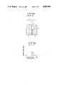
- Such magnetic recording head is formed generally as shown in FIG. 1(A) where ferrite core elements 2, 3 of metal oxide magnetic material are connected through a gap spacer 1 of non-magnetic material.
- the gap spacer 1 is formed by sputtering or the like provides a gap length t for the erasing head.
- the erasing head is provided with a coil winding hole 4 which is formed at the trailing side of the magnetic tape relative to the travelling direction as shown by an arrow X with respect to the erasing head for performing tracking operation.
- a coil wound through the coil winding head 4 is supplied with an erasing signal at a frequency of about 5 MHz, for example.
- a magnetic field which is sufficient to magnetize the magnetic tape to saturation is generated in the gap, and as the magnetic tape travels the magnetic field which is applied to the magnetic tape decreases gradually from a magnetic field sufficient to magnetize the magnetic tape to saturation and thereby the residual magnetization of the magnetic tape goes to zero and the magnetically recorded signal on the magnetic tape is erased.
- the distribution of the magnetic field intensity generated by the magnetic gap of the magnetic erasing head has the characteristics shown in FIG. 1(B) where the magnetic field intensity distribution becomes sharp at the trailing side (region designated by f) in the travelling direction of the tape with respect to the magnetic gap forming position. Consequently, the erasing signal of a prescribed frequency may be recorded on the magnetic tape or such re-recording phenomenon may occur such that a signal recorded on the magnetic tape which being erased is re-recorded with high-frequency bias on the magnetic tape using the erasing signal of the prescribed frequency as a high-frequency bias.
- the magnetic tape such as so-called metal magnetic tape comprising metal magnetic powders having large coercive force is used.
- magnetic material having higher saturation magnetic flux density than ferrite for example, magnetic alloy of Fe-Al-Si series, i.e. so-called sendust alloy is used in a part of the core element.
- the magnetic erasing head in the prior art has disadvantages in that the erasing efficiency is not sufficient.
- a magnetic erasing head which comprises a pair of magnetic core elements defining an erasing magnetic gap therebetween and facing a travelling magnetic recording medium, a coil winding opening is provided adjacent to the erasing magnetic gap on one of the magnetic core elements and is located on a trailing side relative to travelling of the magnetic recording medium and defines the depth of the erasing magnetic gap, and a coil is wound through the coil winding opening and is provided with an alternating current for generating an erasing magnetic field in the erasing gap, and the coil winding opening defining a core portion adjacent the trailing side having a thickness which is substantially equal to the depth of the erasing magnetic gap.
- FIG. 1(A) is a schematic sectional view of a magnetic erasing head in the prior art
- FIG. 1(B) is a characteristic diagram illustrating magnetic field intensity distribution of the magnetic erasing head in FIG. 1(A);
- FIG. 2(A) is a perspective view of a magnetic erasing head according to the invention.
- FIG. 2(B) is a view of the magnetic erasing head illustrating a surface opposed to a magnetic tape according to the invention
- FIG. 3 is a sectional view taken in line I--I of FIG. 2(B);
- FIG. 4(A) is a characteristic diagram illustrating magnetic field intensity distribution of the magnetic erasing head in FIG. 2(A);
- FIG. 4(B) is a fragmentary sectional view taken in line I--I of FIG. 2(B);
- FIG. 5 and FIG. 6 are sectional view of the magnetic erasing head illustrating other embodiment of the invention.
- FIG. 2(A) shows a perspective view of a magnetic erasing head according to the invention
- FIG. 3 shows a sectional view taken in line I--I of FIG. 2(B).
- the magnetic erasing head is used, for example, as a rotating erasing head for a VTR, and a magnetically recorded signal on a magnetic tape, for example, as a magnetic recording medium is erased by an erasing signal with a frequency of 5 MHz for example.
- the magnetic erasing head is composed of a pair of core elements 10, 11 of soft magnetic material, e.g.
- the pair of core elements 10, 11 are connected by melt-bonding through a gap spacer 20 formed by sputtering a film of non-magnetic material, e.g. silicon dioxide SiO 2 using glass 21 of non-magnetic material.
- the gap spacer 20 provides a gap length t, and an erasing magnetic field is generated in the gap.
- a coil is wound through the coil winding hole 12 and is supplied with an erasing signal, and the coil winding hole 12 defines the gap depth d.
- the coil winding hole 12 is formed in the core element 11 such that an arm 13 is formed on the magnetic tape contacting side, and the distance between the upper end (o) and the lower end (p) of the end surface of the arm 13, i.e., the abutting surface of the gap spacer 20 with the core element 10, becomes the gap depth d. That is, the gap depth d being the distance between the upper end (o) and the lower end (p) corresponds to the length of the abutting surface in the perpendicular direction to the contacting surface with the magnetic tape.
- the thickness of the arm 13 in the depth direction adjacent to the magnetic gap is substantially equal to the gap depth in the direction of the trailing side.
- the surface continuing to the point defining the gap depth d of the coil winding hole 12, i.e. the lower end forms the region having a thickness which is substantially equal to the gap depth adjacent to the magnetic gap of the core element 11.
- FIG. 4(A) the distribution of the erasing magnetic field intensity generated by the gap becomes as shown in FIG. 4(A) where the distribution of the magnetic field intensity becomes asymmetric with respect to the gap forming position. That is, the field intensity distribution at the head trailing side (region designated by h in the figure) in the direction of travel of the tape has a gentle slope.
- the magnetic field intensity is the ordinate and the distance of tape travel is the abscissa.
- FIG. 4(B) is shown with a position corresponding to FIG. 4(A) and is a fragmentary sectional view taken in line I--I of FIG. 2(B).
- the reason that the magnetic field intensity distribution has a gentle slope at the trailing side is that as the erasing current flowing in the coil wound through the coil winding hole 12 increases, the arm 13 of the core element 11 is gradually magnetically saturated and the magnetically saturated region extends is the direction of the magnetic tape trailing side as compared to the conventional erasing head. Consequently, when the magnetic field applied to the magnetic tape decreases gradually sufficiently to saturate the magnetic tape as the magnetic tape travels and the residual magnetization on the magnetic tape approaches zero, neither the erasing signal of the prescribed frequency is recorded on the magnetic tape nor a re-recording phenomenon occurs that the signal remains on the tape.
- a core element 24 at the leading side of the magnetic tape relative to the direction of travel may be constituted using soft magnetic material having a high saturation magnetic flux density, for example, Fe-Al-Si series alloy, i.e., so-called sendust alloy, in order to correspond to metal magnetic tape having high coercive force Hc.
- soft magnetic material having a high saturation magnetic flux density for example, Fe-Al-Si series alloy, i.e., so-called sendust alloy
- a thin film 25 of magnetic material such as sendust may be formed only at the leading side of the gap spacer 20.
- the magnetic field intensity generated from the magnetic gap can be strengthened, and if material having a higher saturation magnetic flux density is located at the leading side with respect to the gap spacer or material having a lower saturation magnetic flux density is located at the trailing side, the magnetic field intensity distribution at the trailing side will have a gentle slope. Consequently, when magnetic material of a high saturation magnetic flux density is used corresponding to the metal magnetic tape having high coercive force, the phenomenon of recording of the erasing signal or the re-recording phenomenon of the prior art can be effectively prevented. Also such phenomenon particularly occurring at the evaporated metal magnetic tape of this magnetic layer can be prevented, and the erasing efficiency to erase the signal recorded on the evaporated metal magnetic tape can be improved according to the invention.
- Mn-Zn ferrite As well as Ni-Zn ferrite may be used.
- amorphous magnetic material having a composition represented by MX may be used. If M designates Fe, Co (cobalt), Ni, and X designates for example Si, B (boron), P (phosporous), C (carbon). Specific examples of the amorphous material is magnetic material of the Fe-Co-Si-B series.
- the magnetic erasing head of the invention may be used not only as a rotating erasing head for a VTR but also as a fixed type erasing head.
- a pair of core elements of soft magnetic material are connected through a gap spacer, and the core element at trailing side of a magnetic recording medium is provided with a coil winding hole, and a surface continuing to a point which defines the gap depth of the coil winding hole forms a region having a thickness which is substantially equal to the gap depth adjacent the magnetic gap of the core element at the trailing edge.
- the distribution of the magnetic field intensity generated by the magnetic gap has a gentle slope in the direction of the trailing edge with respect to the gap forming position, thereby neither the erasing signal is recorded on the magnetic medium nor does a re-recording phenomenon occur such that signals are recorded on the magnetic recording medium which are being erased are re-recorded on the magnetic recording medium using the erasing signal as bias.
- the erasing efficiency of the magnetic erasing head can be improved according to the invention.
Landscapes
- Engineering & Computer Science (AREA)
- Manufacturing & Machinery (AREA)
- Magnetic Heads (AREA)
Applications Claiming Priority (2)
| Application Number | Priority Date | Filing Date | Title |
|---|---|---|---|
| JP58-198932 | 1983-10-24 | ||
| JP58198932A JPS6089805A (ja) | 1983-10-24 | 1983-10-24 | 磁気消去ヘツド |
Related Parent Applications (1)
| Application Number | Title | Priority Date | Filing Date |
|---|---|---|---|
| US06664217 Continuation | 1984-10-24 |
Publications (1)
| Publication Number | Publication Date |
|---|---|
| US4805058A true US4805058A (en) | 1989-02-14 |
Family
ID=16399362
Family Applications (1)
| Application Number | Title | Priority Date | Filing Date |
|---|---|---|---|
| US07/028,077 Expired - Fee Related US4805058A (en) | 1983-10-24 | 1987-03-20 | Magnetic erasing head |
Country Status (4)
| Country | Link |
|---|---|
| US (1) | US4805058A (ja) |
| EP (1) | EP0144139B1 (ja) |
| JP (1) | JPS6089805A (ja) |
| DE (1) | DE3476133D1 (ja) |
Cited By (3)
| Publication number | Priority date | Publication date | Assignee | Title |
|---|---|---|---|---|
| US4922086A (en) * | 1987-10-19 | 1990-05-01 | Banctec, Inc. | Write head apparatus for recognizing magnetic characters and method therefor |
| US5029032A (en) * | 1988-10-19 | 1991-07-02 | Tdk Corporation | Magnetic head for high density recording |
| GB2278489B (en) * | 1992-11-11 | 1996-10-23 | Japan Energy Corp | Magnetic head |
Families Citing this family (2)
| Publication number | Priority date | Publication date | Assignee | Title |
|---|---|---|---|---|
| DE3688971T2 (de) * | 1985-11-13 | 1993-12-09 | Sanyo Electric Co | Magnetisches Aufnahmegerät. |
| DE3843123A1 (de) * | 1988-12-22 | 1990-06-28 | Foerster Inst Dr Friedrich | Vorrichtung zum bewegen von schubschlaeuchen im inneren von rohren |
Citations (10)
| Publication number | Priority date | Publication date | Assignee | Title |
|---|---|---|---|---|
| US4176384A (en) * | 1978-05-15 | 1979-11-27 | Yang Electromagnetics Systems Inc. | Magnetic recording head assembly defining precision gaps |
| US4180835A (en) * | 1977-06-09 | 1979-12-25 | Sony Corporation | Magnetic erasing head with gaps utilizing high flux density and high permeability |
| US4205356A (en) * | 1977-06-17 | 1980-05-27 | Canon Kabushiki Kaisha | Erasing head |
| JPS55125521A (en) * | 1979-03-22 | 1980-09-27 | Tdk Corp | Erasing head for magnetic tape of high magnetic force |
| US4316228A (en) * | 1979-03-23 | 1982-02-16 | Hitachi, Ltd. | Magnetic head |
| JPS5817522A (ja) * | 1981-07-22 | 1983-02-01 | Matsushita Electric Ind Co Ltd | 磁気ヘツド及びその製造法 |
| US4450494A (en) * | 1980-09-22 | 1984-05-22 | Hitachi Ltd. | Magnetic head |
| US4476509A (en) * | 1981-02-20 | 1984-10-09 | Hitachi, Ltd. | Thin film magnetic head and method of manufacturing the same |
| EP0125891A1 (en) * | 1983-05-11 | 1984-11-21 | Hitachi, Ltd. | Composite type magnetic head and its manufacturing method |
| US4559572A (en) * | 1983-02-04 | 1985-12-17 | Hitachi, Ltd. | Magnetic head and method of fabricating same |
Family Cites Families (1)
| Publication number | Priority date | Publication date | Assignee | Title |
|---|---|---|---|---|
| US4217613A (en) * | 1978-11-06 | 1980-08-12 | Rca Corporation | Magnetic transducer head core |
-
1983
- 1983-10-24 JP JP58198932A patent/JPS6089805A/ja active Pending
-
1984
- 1984-10-24 DE DE8484307295T patent/DE3476133D1/de not_active Expired
- 1984-10-24 EP EP84307295A patent/EP0144139B1/en not_active Expired
-
1987
- 1987-03-20 US US07/028,077 patent/US4805058A/en not_active Expired - Fee Related
Patent Citations (10)
| Publication number | Priority date | Publication date | Assignee | Title |
|---|---|---|---|---|
| US4180835A (en) * | 1977-06-09 | 1979-12-25 | Sony Corporation | Magnetic erasing head with gaps utilizing high flux density and high permeability |
| US4205356A (en) * | 1977-06-17 | 1980-05-27 | Canon Kabushiki Kaisha | Erasing head |
| US4176384A (en) * | 1978-05-15 | 1979-11-27 | Yang Electromagnetics Systems Inc. | Magnetic recording head assembly defining precision gaps |
| JPS55125521A (en) * | 1979-03-22 | 1980-09-27 | Tdk Corp | Erasing head for magnetic tape of high magnetic force |
| US4316228A (en) * | 1979-03-23 | 1982-02-16 | Hitachi, Ltd. | Magnetic head |
| US4450494A (en) * | 1980-09-22 | 1984-05-22 | Hitachi Ltd. | Magnetic head |
| US4476509A (en) * | 1981-02-20 | 1984-10-09 | Hitachi, Ltd. | Thin film magnetic head and method of manufacturing the same |
| JPS5817522A (ja) * | 1981-07-22 | 1983-02-01 | Matsushita Electric Ind Co Ltd | 磁気ヘツド及びその製造法 |
| US4559572A (en) * | 1983-02-04 | 1985-12-17 | Hitachi, Ltd. | Magnetic head and method of fabricating same |
| EP0125891A1 (en) * | 1983-05-11 | 1984-11-21 | Hitachi, Ltd. | Composite type magnetic head and its manufacturing method |
Non-Patent Citations (2)
| Title |
|---|
| W. Nystrom, "Hybrid Ferrite Head for High-Density Recording", IBM Technical Disclosure Bulletin, vol. 12, No. 12, May 1970. |
| W. Nystrom, Hybrid Ferrite Head for High Density Recording , IBM Technical Disclosure Bulletin, vol. 12, No. 12, May 1970. * |
Cited By (4)
| Publication number | Priority date | Publication date | Assignee | Title |
|---|---|---|---|---|
| US4922086A (en) * | 1987-10-19 | 1990-05-01 | Banctec, Inc. | Write head apparatus for recognizing magnetic characters and method therefor |
| US5029032A (en) * | 1988-10-19 | 1991-07-02 | Tdk Corporation | Magnetic head for high density recording |
| GB2278489B (en) * | 1992-11-11 | 1996-10-23 | Japan Energy Corp | Magnetic head |
| US5572390A (en) * | 1992-11-11 | 1996-11-05 | Japan Energy Corporation | Magnetic head including an apex portion with two chamfered portions having optimized angles |
Also Published As
| Publication number | Publication date |
|---|---|
| DE3476133D1 (en) | 1989-02-16 |
| JPS6089805A (ja) | 1985-05-20 |
| EP0144139A1 (en) | 1985-06-12 |
| EP0144139B1 (en) | 1989-01-11 |
Similar Documents
| Publication | Publication Date | Title |
|---|---|---|
| US4251842A (en) | Magnetic recording and reproducing device | |
| EP0128625A1 (en) | Magnetic transducing head for writing information on high-coercive recording media | |
| US4631612A (en) | Magnetic recording and reproducing system | |
| US4639810A (en) | Magnetic head for perpendicular magnetization | |
| JPH0518164B2 (ja) | ||
| JPH0152802B2 (ja) | ||
| JPH1186218A (ja) | 薄膜磁気ヘッド | |
| JPS6218966B2 (ja) | ||
| US4805058A (en) | Magnetic erasing head | |
| JPH0467245B2 (ja) | ||
| EP0483785B1 (en) | Magnetic recording and/or reproducing method and magnetic head for effecting said method | |
| JPH0327963B2 (ja) | ||
| JPH0234083B2 (ja) | ||
| JPH08115507A (ja) | 磁気ヘッド | |
| JPS6220606B2 (ja) | ||
| JPS599410Y2 (ja) | 磁気ヘツド | |
| JPS6240606A (ja) | 磁気消去ヘツド | |
| JPS62145512A (ja) | 磁気消去ヘツド | |
| JPH01122004A (ja) | 磁気ヘツド装置 | |
| JPH05182111A (ja) | 光磁気ディスク装置 | |
| JPH05174325A (ja) | 複合型磁気ヘッドコア及び浮上型磁気ヘッド | |
| JPH05182136A (ja) | 複合型磁気ヘッドコア及び浮上型磁気ヘッド | |
| JPS62245507A (ja) | 消去用磁気ヘツド | |
| JPH01229412A (ja) | 磁気ヘッド | |
| Sin et al. | Effect of induced uniaxial magnetic anisotropy of Ni-Fe keeper layer on the recording properties of longitudinal Co-Cr-Ta/Cr thin film media |
Legal Events
| Date | Code | Title | Description |
|---|---|---|---|
| FPAY | Fee payment |
Year of fee payment: 4 |
|
| REMI | Maintenance fee reminder mailed | ||
| LAPS | Lapse for failure to pay maintenance fees | ||
| FP | Lapsed due to failure to pay maintenance fee |
Effective date: 19970219 |
|
| STCH | Information on status: patent discontinuation |
Free format text: PATENT EXPIRED DUE TO NONPAYMENT OF MAINTENANCE FEES UNDER 37 CFR 1.362 |