US4564754A - Method and apparatus for optically measuring a current - Google Patents
Method and apparatus for optically measuring a current Download PDFInfo
- Publication number
- US4564754A US4564754A US06/472,834 US47283483A US4564754A US 4564754 A US4564754 A US 4564754A US 47283483 A US47283483 A US 47283483A US 4564754 A US4564754 A US 4564754A
- Authority
- US
- United States
- Prior art keywords
- light
- faraday effect
- glass
- effect glass
- faraday
- Prior art date
- Legal status (The legal status is an assumption and is not a legal conclusion. Google has not performed a legal analysis and makes no representation as to the accuracy of the status listed.)
- Expired - Lifetime
Links
Images


Classifications
-
- G—PHYSICS
- G01—MEASURING; TESTING
- G01R—MEASURING ELECTRIC VARIABLES; MEASURING MAGNETIC VARIABLES
- G01R15/00—Details of measuring arrangements of the types provided for in groups G01R17/00 - G01R29/00, G01R33/00 - G01R33/26 or G01R35/00
- G01R15/14—Adaptations providing voltage or current isolation, e.g. for high-voltage or high-current networks
- G01R15/24—Adaptations providing voltage or current isolation, e.g. for high-voltage or high-current networks using light-modulating devices
- G01R15/245—Adaptations providing voltage or current isolation, e.g. for high-voltage or high-current networks using light-modulating devices using magneto-optical modulators, e.g. based on the Faraday or Cotton-Mouton effect
- G01R15/246—Adaptations providing voltage or current isolation, e.g. for high-voltage or high-current networks using light-modulating devices using magneto-optical modulators, e.g. based on the Faraday or Cotton-Mouton effect based on the Faraday, i.e. linear magneto-optic, effect
Definitions
- the present invention relates to method and apparatus for optically measuring a current, and more particularly to an optical current measuring apparatus suitable to measure a current flowing in a high voltage conductor.
- a winding type current transformer has been used in current measurement for the measurement or protection of a commercial power system.
- the prior art winding type current transformer however, has problems in insulation and structure when a transmitted voltage is very high such as 500 kV-700 kV, and the apparatus becomes large in size and expensive.
- V is a Verdet's constant
- H is a magnetic field strength in a direction of light propagation
- L is a length of the glass in the direction of the light propagation
- light conduction rods may be arranged in place of the reflecting mirrors, analyzers may be provided in input paths of the light conduction rods and polarizers may be provided in output paths.
- the above construction has the following disadvantages. It is difficult to maintain a relative position of the polarization member and the reflecting mirror or the light conduction rod at a high precision.
- the linearly polarized light is elliptically polarized by a phase change of the light by the reflection in the reflection mirror or the light conduction rod and a detectable polarization rotation angle is significantly reduced making the current detection difficult.
- the polarization members have the same sensitivity, but the sensitivities of the polarization members to the magnetic fields substantially differ from each other because the lights transmitted through the reflection mirrors or the light conduction rods are no longer linearly polarized. This makes the high precision measurement of the current of the conductor difficult.
- the U.S. Pat. No. 3,746,983 proposes to surround a current flowing conductor by a rectangular Faraday effect member having mirror surfaces at four corners and an inner surface having reflecting surfaces on both sides thereof at a portion along a linear side.
- a light beam from a light source is polarized by a polarizing filter and applied to one side of the inner surface of the Faraday effect member and reflected thereby at an angle of 45 degrees and reflected by each of the four corners to circulate the member, and emitted outwardly from the other side of the inner surface.
- the emitted light beam further passes through another Faraday effect member having a coil wound thereon so that a polarization rotation angle can be detected.
- a current is supplied to the coil from a variable current source so that a magnetic field produced thereby rotates the polarization plane of the light beam passing through another Faraday effect member to return to a polarization plane of an incident light on the rectangular Faraday effect member surrounding the conductor.
- a current of the coil is metered under this condition to measure the current of the conductor which is proportional to the current of the coil.
- the total reflection of the light beam in the rectangular Faraday effect member surrounding the conductor has a phase difference between a component perpendicular to the reflection plane and a component parallel to the reflection plane.
- the linear polarization at the incident point is changed to the elliptic polarization as described above, making the detection of the current of the conductor quite difficult.
- a Faraday effect glass has an opening at a center thereof so that a conductor under measurement passes through the opening to cross perpendicular to the Faraday effect glass, and the Faraday effect glass has at least two total reflection surfaces on a periphery thereof to cause a light to circulate a light path around the conductor under measurement so that the light circulated around the light path is made a polarization rotation by a Faraday effect so as to constitute the optical current measuring apparatus.
- the reflected light at a changing point of the light path direction in the Faraday effect glass is totally internally reflected twice in order to prevent the distortion of the linear polarization (i.e. to prevent the linear polarization from converting to the elliptic polarization).
- a plurality of Faraday effect glasses of different materials are arranged in parallel and one of the Faraday effect glasses is selected in accordance with a range of measurement to allow a wide range of measurement.
- FIG. 1 shows a configuration of an optical current measuring apparatus in accordance with a first embodiment of the present invention
- FIG. 2 shows a front view of a Faraday effect glass used in the first embodiment
- FIG. 3 shows a front view of another Faraday effect glass used in the first embodiment
- FIG. 4 shows a configuration of an optical current measuring apparatus in accordance with a second embodiment of the present invention
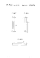
- FIGS. 5, 6, 7, 8 and 9 show a front view, a plan view, a left side view, a right side view and a bottom view, respectively, of a Faraday effect glass used in the second embodiment;
- FIGS. 10, 11, 12 and 13 show a perspective view, a front view, a right side view and a bottom view, respectively, of another Faraday effect glass used in the second embodiment;
- FIGS. 14, 15 and 16 show a front view, a right side view and a bottom view, respectively, of a further Faraday effect glass used in the second embodiment
- FIG. 17 shows a configuration of other embodiment of the optical current measuring apparatus and method of the present invention.
- FIG. 18 shows a configuration of a further embodiment of the present invention.
- FIG. 19 shows a schematic diagram of a further embodiment of the optical current measuring appparatus of the present invention.
- FIG. 20 shows a characteristic chart of an output of the optical current measuring apparatus.
- An input light path comprises a light source 10 for emitting light, an optical fiber 10A for transmitting the light from the light source 10, a condenser lens 11 for condensing the light emitted from the optical fiber 10A and preventing scattering of the light and a polarizer 12 made of a high molecule film, a vapor deposition film or a polarizing prism for linearly polarizing the light from the condenser lens 11.
- the light source 10 may be a light emitting diode, a laser diode or a laser of another type.
- the output light from the polarizer 12 is directed to a Faraday effect glass 13.
- FIG. 2 shows a front view of the Faraday effect glass 13.
- An incident light goes straight along a light path of the Faraday effect glass 13 as shown by a solid line, it is reflected by a first total reflection plane (having an angle of 45 degrees to the incident light), goes straight toward a second total reflection plane, it is reflected by the second total reflection plane and then reflected by a third total reflection plane. The reflected light then goes out of the Faraday effect glass 13 transversely to the incident light.
- a center area of the Faraday effect glass 13 is cut away to permit the insertion of a conductor 20 thereinto.
- the light circulates around the conductor 20 under measurement by the three total reflection planes provided in the Faraday effect glass 13.
- the linearly polarized light propagates through the Faraday effect glass while it inter-links with the conductor 20 under measurement (primary conductor).
- a polarization rotation angle ⁇ by the Faraday effect after one circulation around the conductor 20 is given by
- V is a Verdet's constant
- H is a magnetic field strength around the conductor
- I is a current under measurement
- the polarization rotation is exactly proportional to the current under measurement. Accordingly, the current is measured more precisely than the prior art apparatus.
- the light emitted from the Faraday effect glass 13 is sent to an output light path.
- the output light is received by an analyzer 14 such as a polarization prism which splits the light into two light beams.
- the two light beams are condensed by condenser lenses 15 and 16.
- the linearly polarized light condensed by the condenser lens 15 is transmitted to a light detector 19 through an optical fiber 17, and the linearly polarized light condensed by the condenser lens 16 is transmitted to the light detector 19 through an optical fiber 18.
- the light detector 19 calculates a Faraday rotation angle from (Pa-Pb)/(Pa+Pb) based on the two linearly polarized lights Pa and Pb.
- a material of the Faraday effect glass may be flint glass such as lead glass or heavy flint glass, fused glass such as crown glass or silica glass, or porcelain glass.
- the material of the Faraday effect glass should be properly selected because the Verdet's constant and a detectable maximum current differ depending on a wavelength of the light source 10 as shown in Tables 1 and 2.
- the light path is formed by the Faraday effect glass, it is hardly subjected to a surrounding temperature and a mechanical vibration and a variation of the light path can be substantially neglected. As a result, a high precision measurement is stably attained over an extended period.
- the number of times of the total reflection in the Faraday effect glass is three. Since the present invention can be realized by circulating the light path around the conductor, a Faraday effect glass having a shape as shown in FIG. 3 may be used to reduce the number of times of reflection.
- the total reflection planes in the Faraday effect glasses shown in FIGS. 2 and 3 may be formed by optically polishing or plating silver or aluminum.
- the Faraday effect glasses shown in FIGS. 2 and 3 are simple in structure and easy to manufacture but the total internal reflection occurs only once for each deflection of the light path. As a result, the linearly polarized light is readily changed to the elliptically polarized light for each total internal reflection and hence the Faraday rotation angle may be reduced and the sensitivity may be lowered.
- An embodiment which resolves the above problem is described below.
- FIG. 4 A configuration of a second embodiment of the optical current measuring apparatus of the present invention is shown in FIG. 4, in which the like elements to those shown in FIG. 1 are designated by the like numerals.
- the total internal reflection planes of the Faraday effect glass are improved such that the total internal reflection occurs twice at each light path in the Faraday effect glass to prevent the reduction of the sensitivity.
- FIGS. 5 to 9 An example of a shape of the Faraday effect glass used in the present embodiment is shown in FIGS. 5 to 9.
- the total internal reflection occurs six times, that is, at points b, c, d, e, f and g. It is desirable that axial distances between the points b and c, d and e and f and g are as small as possible in order to prevent the affect by the magnetic fields created by other conductors.
- the light from the polarizer 12 is applied to the point a, goes straight as shown by a solid line, totally reflected at the point b and deflected by 90 degrees, totally reflected at the point c and goes leftward perpendicular to the incident light.
- the light is totally reflected at the point d and axially deflected (and goes straight in the opposite direction to the light going to the point c), and it is totally reflected at the point e downward in the opposite direction to the incident light.
- the linearly polarized light is reflected at the point f frontward and then reflected rightward so that the light is emitted from the point h with an angle of 90 degrees to the incident light.
- the light circulates around the conductor 20 under measurement six times by total internal reflection. By total internal reflecting the light twice at a short interval at each light path deflection point, an ideal Faraday rotation can be attained.
- the rotation of the linearly polarized plane by the Faraday effect is proportional to a magnetic field strength parallel to the light path and a light path length. Since the currents flowing in the other conductors than the conductor 20 which are in the vicinity of the conductor 20 are nulled by the integration along the light path in the Faraday effect glass 30, an effect thereby can be neglected. Accordingly, the Faraday rotation angle ⁇ by the linearly polarized light circulated around the conductor 20 is essentially proportional to the current flowing in the conductor 20. Since the total internal reflection planes of the Faraday effect glass 30 can be readily prepared even on a peripheral area by optically polishing, they can be formed without bonding.
- the present embodiment has an improved sensitivity over the embodiment of FIG. 1.
- the Faraday effect glass 30 shown in FIGS. 5 to 9 may be further improved to facilitate the manufacture. Examples thereof are shown in FIGS. 10 to 13 and FIGS. 14 to 16.
- a corner of a Faraday effect glass 40 which forms a light input section and a light output section is cut away and a rectangular prism 41 is bonded to that area.
- the polishing of the right side is facilitated (because each of the optically polished surfaces is planar and no stepping is required) and the manufacture is facilitated.
- the light transmitted through the polarizer goes into the Faraday effect glass 40 from one side of the rectangular prism 41 as shown in FIG. 10 and is totally internally reflected six times, that is, twice at each of three corners at a short interval as shown by a chain line, and goes out of the other side of the rectangular prism 41.
- rectangular prisms 51 and 52 are bonded to a corner of a Faraday effect glass 50 which functions as a light input section a and a light output section b.
- a Faraday effect glass 50 which functions as a light input section a and a light output section b.
- the Faraday effect glass inter-links (traverses) the conductor under measurement and the portions which cause the Faraday rotation are in union and not affected by the currents flowing in the other conductors. Accordingly, a high precision current measurement is stably attained over an extended period.
- the polarization plane is rotated by an angle proportional to a product of a length of the glass and a magnetic field component along the direction of the light propagation.
- a polarization prism such as a Wollaston prism or a polarization beam splitter is used as an analyzer.
- the two light beams emitted from the analyzer are split as lights of energies k(1+sin2 ⁇ ) and k(1-sin2 ⁇ ) where ⁇ is the Faraday rotation angle and k is a constant representing a light transmission efficiency.
- a 1 b 1 C 1 is made to be equal to a 2 b 2 C 2 so that the Faraday rotation angle is proportional to (V 1 -V 2 )/(V 1 +V 2 ). Since this method uses a ratio of the outputs of the two light beams, it is not affected by a variation of the transmitted light.
- an A.C. (Alternating Current) component of the current is utilized to constantly monitor and detected the variations of a 1 b 1 and a 2 b 2 .
- the Faraday rotation angle ⁇ is represented by Ve(I DC +I AC ) and hence
- the A.C. component of the electric signal V 1 and the A.C. component of the electric signal V 2 are detected and C 1 and C 2 are adjusted such that the A.C. component of V 1 is equal to the A.C. component of V 2 .
- FIG. 17 A further embodiment of the optical current measuring apparatus and method of the present invention is explained with reference to FIG. 17.
- the conductor 20 through which the current under measurement flows extends through a Faraday effect glass 13 like in the previous embodiments.
- the light from the light source 10 is transmitted through the optical fiber 10A, condensed by the condenser lens 11 and the condensed light is directed into the Faraday effect glass 30 through the polarizer 12.
- the light emitted from the Faraday effect glass 30 goes into the analyzer 14 where it is split into two light beams which are directed to the condenser lenses 15 and 16, respectively.
- the lights condensed by the condenser lenses 15 and 16 pass through the optical fibers 17 and 18, respectively and are directed to photo-diodes 60 and 61, respectively, which function as light detectors.
- the outputs of the photo-diodes 60 and 61 are supplied to current-to-voltage conversion amplifiers 62 and 63, respectively.
- An output of the first current-to-voltage conversion amplifier 63 is supplied to a band-pass filter 64, a subtractor 65 and an adder 66, and an output of the second current-to-voltage conversion amplifier 62 is supplied to a band-pass filter 67 and a multiplier 68.
- An output of the band-pass filter 64 is supplied to a divider 71 through a detector 69 and an integrator 70, and an output of the band-pass filter 67 is supplied to the other terminal of the divider 71 through a detector 72 and an integrator 73.
- An output of the divider 71 is supplied to the other terminal of the multiplier 68 and an output of the multiplier 68 is supplied to the subtractor 65 and the adder 66, and an output of the adder 66 is supplied to a divider 74.
- An output of the subtractor 65 is also applied to the divider 74.
- the condenser lens 11 and the polarizer 12 In order to detect the Faraday rotation angle ⁇ when the light from the light source 10 goes into the Faraday effect glass 30 through the optical fiber 10A, the condenser lens 11 and the polarizer 12 and goes out after one circulation, the emitted light is split into the two light beams by the analyzer 14 and these two light beams are condensed by the condenser lenses 15 and 16 and efficiently directed into the optical fibers 17 and 18, and the lights transmitted therethrough are converted to the photocurrent by the photo-diodes 60 and 61 to produce the electric signals.
- the current outputs from the photo-diodes 62 and 63 are converted to the voltage signals by the current-to-voltage conversion amplifiers 62 and 63.
- the A.C. components of the output voltage signals V 1 and V 2 of the current-to-voltage amplifiers 62 and 63 are extracted by the band-pass filters 64 and 67, and they are converted to D.C. signals by the detectors 69 and 72 and the D.C. signals are integrated by the gated integrators 70 and 73. Through the integration, the affect by the noises included in the D.C. signal can be reduced.
- the output of the integrator 70 becomes lower than the output of the integrator 73 by the temperature characteristics or the aging effects of the optical fibers 17 and 18 and the photo-diodes 60 and 61, a ratio of those outputs is calculated by the divider 68 and it is multiplied to the output signals of the current-to-voltage amplifiers 62 and 63 by the multiplier 68 to correct the error.
- the adder 66, the subtractor 65 and the divider 74 are well-known arithmetic circuits to detect the Faraday rotation angle based on the fact that the Faraday rotation angle ⁇ is proportional to (V 1 -V 2 )/(V 1 +V 2 ).
- the ratio of the outputs of the integrator 70 and the integrator 73 which is initially set to approximately unity may exceed unity due to dew condensation on one of the optical fibers or breakage of one of the optical fibers.
- This abnormal condition can also be monitored by the illustrated circuit to diagnose the failure when the operation condition deviates from a normal range.
- the light emitted from the Faraday effect glass is photo-electrically converted by the photo-diodes 60 and 61 and the photo-currents are supplied to the arithmetic circuit through the current-to-voltage conversion amplifiers 62 and 63 having the amplification factors C 1 and C 2 , respectively, and the arithmetic circuit extracts the A.C. components of the outputs and corrects the measurement error due to environment condition variation such as the temperature characteristics and the aging effects of the components by the divider 71 and the multiplier 68 based on the change of the ratio of the A.C. components so that a high precision current measurement is stably attained over an extended period.
- environment condition variation such as the temperature characteristics and the aging effects of the components by the divider 71 and the multiplier 68 based on the change of the ratio of the A.C. components so that a high precision current measurement is stably attained over an extended period.
- the present embodiment uses the analog arithmetic circuit, the calibration speed for the error is fast
- FIG. 18 another embodiment of the optical current measuring apparatus of the present invention is explained.
- the light emitted from the light source 10 goes into the Faraday effect glass 30 through the same path as that of FIG. 17, and the light emitted therefrom goes into the photo-diodes 60 and 61 through the same path.
- the output current signals from the photo-diodes 60 and 61 are supplied to the current-to-voltage conversion amplifiers 62 and 63, and the outputs therefrom are supplied to analog-to-digital (A/D) converters 75 and 76, and the outputs thereof are supplied to a digital signal processor 77 such as a microprocessor.
- A/D analog-to-digital
- the analog voltage signals from the current-to-voltage conversion amplifiers 62 and 63 are converted to digital signals V 1 and V 2 by the A/D converters 75 and 76, and A.C. components V 1AC and V 2AC in the digital signals V 1 and V 2 are extracted by the digital signal processor 77, which carries out the following arithmetic operations: ##EQU1##
- the signal V is used as a digital output of the optical current measuring apparatus.
- the microprocessor is used as the digital signal processor 77 the construction of the arithmetic unit is simpler than that of FIG. 17 and an error in the arithmetic operation is small because of the digital processing. Accordingly, the measuring apparatus of higher precision can be provided.
- the present invention can measure the current stably over an extended period without increase of precision error due to the temperature characteristics and the aging effects of the components.
- the optical current measuring apparatus which uses the Faraday effect glass has an advantage that it allows the measurement of the current flowing through a particular conductor without being affected by the currents flowing in the other conductors.
- the Faraday rotation angle differs.
- a Faraday effect glass of a single kind of material is used in the optical current measuring apparatus or the optical current transformer, a range of measurement is limited.
- the Faraday rotation angle of a lead glass is 0.12 min./AT for wavelength of 633 nm
- the Faraday rotation angle of a silica glass of the same shape and same dimension is 0.012 min./AT, which is one tenth (1/10) of that of the lead glass.
- the lead glass having a larger rotation angle is suitable for the measurement under a low magnetic field but the rotation angle saturates in a high magnetic field and correct measurement is not attained.
- the silica glass having a smaller rotation angle is suitable for the measurement under a high magnetic field but a sensitivity under a low magnetic field is too low to assure precise measurement.
- an embodiment of the optical current measuring apparatus of the present invention shown in FIG. 19 uses parallelly arranged first Faraday effect glass 80 made of lead glass having an internal light path which links to a conductor 20 and second Faraday effect glass 90 made of silica glass having an internal light path which links to the conductor 20.
- a linearly polarized light is applied to the first Faraday effect glass 80 from a light source 81 through an optical fiber 82, a condenser lens 83 and a polarizer 84.
- the incident linearly polarized light is totally internally reflected twice at each corner of the first planar Faraday effect glass 80, circulates around the conductor 20, is emitted from a light output plane, is split by an analyzer 85 such as a Rochon prism, a Wollaston prism or a polarization beam splitter, and the split light beams are directed to light detectors 88A and 88B such as photo-diodes through condenser lenses 86A and 86B and optical fibers 87A and 87B and they are converted to electric signals.
- the electric signals are then converted to a rotation angle signal Va by an arithmetic circuit 89, an output of which is supplied to an OR gate 100.
- a linearly polarized light is applied to the second Faraday effect glass 90 from a light source 91 through an optical fiber 92, a condenser lens 93 and an analyzer 94.
- the incident linearly polarized light is totally internally reflected twice at each corner of the second Faraday effect glass 90, circulates around the conductor 20, is emitted from a light output plane and is split by an analyzer 95, and the split light beams are directed to light detectors 98A and 98B through condenser lenses 96A and 96B and optical fibers 97A and 97B and they are converted to electric signals.
- the electric signals are similarly converted to a rotation angle signal V b by an arithmetic circuit 99, an output of which is supplied to the OR gate 100.
- a maximum value V of the rotation angle signals V a and V b is produced by the OR gate 100.
- the maximum value signal V from the OR gate 100 or the measuring apparatus changes as shown by a solid line curve in FIG. 20.
- a characteristic curve V a of FIG. 20 which shows a maximum output when a magnetic field created by the current in the conductor 20 is B is obtained.
- the output V of the measuring apparatus derived from the OR gate 100 shows a characteristic as shown by the solid line, which allows the current measurement in a range from a low magnetic field to a high magnetic field.
- the optical current measuring apparatus of the present invention has an advantage that the current can be measured at a high precision over an expanded current range without being affected by the currents in the other conductors.
Landscapes
- Engineering & Computer Science (AREA)
- Power Engineering (AREA)
- Physics & Mathematics (AREA)
- General Physics & Mathematics (AREA)
- Measuring Instrument Details And Bridges, And Automatic Balancing Devices (AREA)
Applications Claiming Priority (6)
| Application Number | Priority Date | Filing Date | Title |
|---|---|---|---|
| JP57035226A JPS58153174A (ja) | 1982-03-08 | 1982-03-08 | 光変流器 |
| JP57-35226 | 1982-03-08 | ||
| JP57110019A JPS59659A (ja) | 1982-06-28 | 1982-06-28 | 磁気光学式電流測定方法及び装置 |
| JP57-110019 | 1982-06-28 | ||
| JP57-144724 | 1982-08-23 | ||
| JP57144724A JPS5935156A (ja) | 1982-08-23 | 1982-08-23 | 光変流器 |
Publications (1)
| Publication Number | Publication Date |
|---|---|
| US4564754A true US4564754A (en) | 1986-01-14 |
Family
ID=27288688
Family Applications (1)
| Application Number | Title | Priority Date | Filing Date |
|---|---|---|---|
| US06/472,834 Expired - Lifetime US4564754A (en) | 1982-03-08 | 1983-03-07 | Method and apparatus for optically measuring a current |
Country Status (3)
| Country | Link |
|---|---|
| US (1) | US4564754A (fr) |
| EP (1) | EP0088419B1 (fr) |
| DE (1) | DE3364239D1 (fr) |
Cited By (53)
| Publication number | Priority date | Publication date | Assignee | Title |
|---|---|---|---|---|
| US4612500A (en) * | 1984-09-04 | 1986-09-16 | Westinghouse Electric Corp. | Temperature stabilized Faraday rotator current sensor by thermal mechanical means |
| US4613811A (en) * | 1984-09-04 | 1986-09-23 | Westinghouse Electric Corp. | Faraday current sensor with fiber optic compensated by temperature, degradation, and linearity |
| US4698497A (en) * | 1986-05-22 | 1987-10-06 | Westinghouse Electric Corp. | Direct current magneto-optic current transformer |
| US4745357A (en) * | 1987-03-23 | 1988-05-17 | Westinghouse Electric Corp. | Optical interface for a magneto-optical current transducer |
| US4768180A (en) * | 1986-03-17 | 1988-08-30 | Laser Magnetic Storage International Company | Multistage tracking system |
| WO1989000767A1 (fr) * | 1987-07-22 | 1989-01-26 | Square D Company | Detecteur de lumiere et circuit de traitement de signaux |
| US4843232A (en) * | 1987-12-28 | 1989-06-27 | Allied-Signal Inc. | Optic switch and speed sensor |
| US4894608A (en) * | 1987-07-22 | 1990-01-16 | Square D Company | Electric current sensor using the faraday effect |
| US4947107A (en) * | 1988-06-28 | 1990-08-07 | Sundstrand Corporation | Magneto-optic current sensor |
| US4973899A (en) * | 1989-08-24 | 1990-11-27 | Sundstrand Corporation | Current sensor and method utilizing multiple layers of thin film magneto-optic material and signal processing to make the output independent of system losses |
| DE3931542A1 (de) * | 1989-09-21 | 1991-04-04 | Siemens Ag | Optischer magnetfeldsensor |
| US5008611A (en) * | 1989-03-14 | 1991-04-16 | Square D Company | Method of eliminating the effects of birefringence from the detection of electric current using Faraday rotation |
| US5093566A (en) * | 1989-07-05 | 1992-03-03 | U.S. Philips Corporation | Radiation detector for elementary particles |
| US5124634A (en) * | 1989-03-14 | 1992-06-23 | Square D Company | Ring optical current transducer |
| DE4342409A1 (de) * | 1993-12-13 | 1995-06-14 | Abb Research Ltd | Massivoptischer Stromsensor |
| US5488291A (en) * | 1993-10-21 | 1996-01-30 | Fuji Electric Co., Ltd. | Optical current transformer |
| DE4436181A1 (de) * | 1994-10-10 | 1996-04-11 | Siemens Ag | Verfahren und Vorrichtung zum Messen einer elektrischen Wechselgröße mit Temperaturkompensation durch Fitting |
| DE4443948A1 (de) * | 1994-12-09 | 1996-06-13 | Siemens Ag | Verfahren und Anordnung zum Messen eines Magnetfeldes mit zwei gegenläufigen Lichtsignalen unter Ausnutzung des Faraday-Effekts mit Kompensation von Intensitätsänderungen |
| DE4446425A1 (de) * | 1994-12-23 | 1996-06-27 | Siemens Ag | Verfahren und Anordnung zum Messen eines Magnetfeldes unter Ausnutzung des Faraday-Effekts mit Kompensation von Intensitätsänderungen und Temperatureinflüssen |
| DE19506169A1 (de) * | 1995-02-22 | 1996-08-29 | Siemens Ag | Verfahren und Anordnung zum Messen eines Magnetfeldes unter Ausnutzung des Faraday-Effekts mit Kompensation von Intensitätsänderungen |
| US5617022A (en) * | 1995-05-01 | 1997-04-01 | Hydro-Aire Division Of Crane Company | Fiberoptic velocity transducer including dielectric coating for filtering and velocity determination |
| US5656934A (en) * | 1993-04-14 | 1997-08-12 | Siemens Aktiengesellschaft | Optical method of measuring an alternating electrical current, including temperature compensation, and a device for carrying out the method |
| WO1997048987A1 (fr) * | 1996-06-14 | 1997-12-24 | Siemens Aktiengesellschaft | Procede d'etalonnage thermique d'un dispositif optique de mesure des champs magnetiques et dispositif de mesure/etalonne selon ce procede |
| WO1998001763A1 (fr) * | 1996-07-09 | 1998-01-15 | Siemens Aktiengesellschaft | Procede de normalisation de l'intensite de capteurs optiques utilises pour mesurer des champs magnetiques ou electriques d'intensite periodiquement variable |
| US5811964A (en) * | 1993-10-01 | 1998-09-22 | Siemens Aktiengelsellschaft | Method and device for measuring an electrical alternating quanity with temperature compensation |
| US5834933A (en) * | 1993-12-13 | 1998-11-10 | Abb Research Ltd. | Method for magnetooptic current measurement and magnetooptic current-measuring device |
| US5844409A (en) * | 1993-10-01 | 1998-12-01 | Siemens Aktiengesellschaft | Method and system for measuring an electric current with two light signals propagating in opposite directions, using the Faraday effect |
| US5892357A (en) * | 1995-12-08 | 1999-04-06 | Lockheed Martin Idaho Technologies Company | Electro-optic voltage sensor for sensing voltage in an E-field |
| US5933238A (en) * | 1996-08-05 | 1999-08-03 | Kabushiki Kaisha Toshiba | Optical current measurement device and method of manufacturing it |
| US6043648A (en) * | 1996-06-14 | 2000-03-28 | Siemens Aktiengesellschaft | Method for temperature calibration of an optical magnetic field measurement array and measurement array calibrated by the method |
| US6281672B1 (en) * | 1996-08-30 | 2001-08-28 | Kabushiki Kaisha Toshiba | Optical current transformer |
| EP1167982A1 (fr) * | 2000-06-30 | 2002-01-02 | Schneider Electric Industries SA | Dispositif de mesure d'un courant électrique par effet faraday |
| US6388434B1 (en) | 2000-01-17 | 2002-05-14 | Bechtel Bwxt Idaho, Llc | Electro-optic high voltage sensor |
| US6798731B1 (en) * | 2000-01-06 | 2004-09-28 | Samsung Electronics Co., Ltd. | Optical pickup for and method of correcting aberration due to thickness variations of optical media |
| US20050005664A1 (en) * | 2003-07-09 | 2005-01-13 | Wesley Scott | System and method for bending strip material to create cutting dies |
| WO2007121592A1 (fr) * | 2006-04-25 | 2007-11-01 | Abb Research Ltd | Capteur de courant a fibre optique avec schéma de détection polarimétrique |
| WO2008065196A2 (fr) * | 2006-11-30 | 2008-06-05 | North Sensor A/S | Ensemble de détection et procédé pour mesurer les éclairs |
| US20090090842A1 (en) * | 2005-03-08 | 2009-04-09 | The Tokyo Electric Power Company, Incorporated | Intensity modulation type optical sensor and optical current / voltage sensor |
| US20090212763A1 (en) * | 2005-03-08 | 2009-08-27 | The Tokyo Electric Power Company, Inc., | Optical sensor, optical current sensor and optical voltage sensor |
| US20110052187A1 (en) * | 2006-12-12 | 2011-03-03 | Abb Technology Ag | Time division multiplexed detector for a magneto-optical current transducer |
| WO2011053657A1 (fr) * | 2009-10-28 | 2011-05-05 | Optisense Network, Inc. | Ensemble capteur optique et procédé de mesure d'un courant dans un système de distribution d'alimentation électrique |
| US9134344B2 (en) | 2009-10-28 | 2015-09-15 | Gridview Optical Solutions, Llc. | Optical sensor assembly for installation on a current carrying cable |
| US9146358B2 (en) | 2013-07-16 | 2015-09-29 | Gridview Optical Solutions, Llc | Collimator holder for electro-optical sensor |
| EP2919022A3 (fr) * | 2007-11-30 | 2015-10-21 | PowerSense A/S | Ensemble de capteur et procédé de mesure des coups de foudre |
| US9535097B2 (en) | 2012-07-19 | 2017-01-03 | Gridview Optical Solutions, Llc. | Electro-optic current sensor with high dynamic range and accuracy |
| US9983237B2 (en) | 2013-03-26 | 2018-05-29 | Mitsubishi Heavy Industries, Ltd. | Lightning current measuring device and lightning current measuring method |
| US20180217186A1 (en) * | 2017-02-01 | 2018-08-02 | Siemens Aktiengesellschaft | Circuit Board with Implanted Optical Current Sensor |
| DE102018216482A1 (de) * | 2018-09-26 | 2020-03-26 | Siemens Aktiengesellschaft | Glasring und Verfahren für optische Strommessungen |
| US20210396786A1 (en) * | 2020-05-06 | 2021-12-23 | Commissariat A L'energie Atomique Et Aux Energies Alternatives | Current sensor based on the faraday effect in an atomic gas |
| RU2767166C1 (ru) * | 2021-04-26 | 2022-03-16 | Акционерное общество "Центральное конструкторское бюро "ФОТОН" | Измеритель тока оптический интерференционный |
| WO2024083489A1 (fr) * | 2022-10-18 | 2024-04-25 | Siemens Energy Global GmbH & Co. KG | Mesure d'un courant électrique à l'aide de deux transformateurs de courant optique |
| WO2024147790A1 (fr) * | 2023-01-05 | 2024-07-11 | Hsp Hochspannungsgeräte Gmbh | Capteur de courant magnéto-optique avec support optique agencé avec des valeurs de constante de verdet distinctes et procédé d'agencement dudit capteur |
| CN112771389B (zh) * | 2018-09-26 | 2024-09-24 | 惠斯普高压电气有限责任公司 | 单体的玻璃环和用于光学电流测量的方法 |
Families Citing this family (19)
| Publication number | Priority date | Publication date | Assignee | Title |
|---|---|---|---|---|
| US4540937A (en) * | 1983-06-07 | 1985-09-10 | Westinghouse Electric Corp. | Electronic circuitry with self-calibrating feedback for use with an optical current sensor |
| DE3923803A1 (de) * | 1989-07-19 | 1991-01-31 | Messwandler Bau Ag | Faseroptische anordnung zum messen der staerke eines elektrischen stromes |
| DE3924369A1 (de) * | 1989-07-22 | 1991-01-31 | Asea Brown Boveri | Verfahren zur messung eines elektrischen feldes oder einer elektrischen spannung und einrichtung zur durchfuehrung des verfahrens |
| EP0477415B1 (fr) * | 1990-09-28 | 1996-03-20 | Asea Brown Boveri Ag | Transducteur optique de courant |
| GB9213736D0 (en) * | 1992-06-29 | 1992-08-12 | Univ Kent Kanterbury | Optical current sensor |
| DE4311328A1 (de) * | 1993-04-06 | 1994-10-13 | Siemens Ag | Optische Meßanordnung zum Messen eines elektrischen Stromes mit verflochtenen Übertragungsleitungen |
| DE4312183A1 (de) * | 1993-04-14 | 1994-10-20 | Siemens Ag | Optisches Meßverfahren zum Messen eines elektrischen Wechselstromes mit Temperaturkompensation und Vorrichtung zur Durchführung des Verfahrens |
| DE4334469C2 (de) * | 1993-10-11 | 1996-08-14 | Felten & Guilleaume Energie | Anordnung zur Auswertung des Meßwerts eines Meßwandlers |
| DE19580887D2 (de) * | 1994-08-23 | 1997-05-28 | Siemens Ag | Verfahren und Anordnung zum Messen von elektrischen Strömen aus wenigstens zwei Meßbereichen |
| DE4432146A1 (de) * | 1994-09-09 | 1996-03-14 | Siemens Ag | Verfahren und Vorrichtung zum Messen eines elektrischen Wechselstromes mit Temperaturkompensation |
| DE19517128A1 (de) * | 1995-05-10 | 1996-11-14 | Siemens Ag | Verfahren und Anordnung zum Messen eines magnetischen Wechselfeldes mit Off-set-Faraday-Rotation zur Temperaturkompensation |
| DE19544778A1 (de) * | 1995-11-30 | 1997-06-05 | Siemens Ag | Verfahren und Anordnung zum Messen einer Meßgröße, insbesondere eines elektrischen Stromes, mit hoher Meßauflösung |
| DE19547021A1 (de) | 1995-12-15 | 1997-06-19 | Siemens Ag | Optisches Meßverfahren und optische Meßanordnung zum Messen einer Wechselgröße mit Intensitätsnormierung |
| DE19601727C1 (de) * | 1996-01-18 | 1997-04-30 | Siemens Ag | Optisches Meßverfahren und optische Meßanordnung zum Messen eines magnetischen Wechselfeldes mit erweitertem Meßbereich und guter Linearität |
| DE19624922A1 (de) * | 1996-06-21 | 1998-01-08 | Siemens Ag | Optisches Meßverfahren und optische Meßanordnung zum Messen einer Wechselgröße mit Temperaturkompensation mit Hilfe von Gleichsignalanteilen |
| WO1998012570A1 (fr) * | 1996-09-20 | 1998-03-26 | Siemens Aktiengesellschaft | Procede servant a obtenir un signal de sortie compense en temperature dans un detecteur optique de mesure de courant |
| EP1055127A1 (fr) | 1998-02-12 | 2000-11-29 | Siemens Aktiengesellschaft | Procede et dispositif pour mesurer un champ magnetique par effet faraday |
| DE102020209699A1 (de) | 2020-07-31 | 2022-02-03 | Siemens Energy Global GmbH & Co. KG | Magnetooptischer Stromwandler und Verfahren zum Erfassen einer Stromstärke |
| CN117054722B (zh) * | 2023-08-11 | 2024-06-18 | 哈尔滨工业大学 | 基于法拉第磁致旋光效应的继电保护用光计算方法及系统 |
Citations (12)
| Publication number | Priority date | Publication date | Assignee | Title |
|---|---|---|---|---|
| US3605013A (en) * | 1968-11-16 | 1971-09-14 | Nippon Selfoc Co Ltd | Current-measuring system utilizing faraday effect element |
| US3675125A (en) * | 1969-12-10 | 1972-07-04 | Bbc Brown Boveri & Cie | Optical wattmeter |
| US3708747A (en) * | 1970-10-23 | 1973-01-02 | Alsthom Savoisienne | Optical current transformer |
| US3743929A (en) * | 1969-11-06 | 1973-07-03 | Alsthom Savoisienne | Current reducers utilizing the faraday effect |
| US3746983A (en) * | 1970-07-20 | 1973-07-17 | Transformatoren Union Ag | Apparatus fur measuring very high currents particularly direct currents |
| US3753101A (en) * | 1971-07-05 | 1973-08-14 | Alsthom Savoisienne | Faraday effect current measuring device |
| US3778619A (en) * | 1971-03-22 | 1973-12-11 | Schlumberger Compteurs | Input connections for differential amplifiers |
| US3810013A (en) * | 1971-06-11 | 1974-05-07 | Siemens Ag | Electro-optical device for measuring the voltage on a high-voltage conductor |
| SU515065A1 (ru) * | 1975-01-27 | 1976-05-25 | Предприятие П/Я В-2015 | Оптико-электронный измеритель тока |
| US4253061A (en) * | 1974-11-09 | 1981-02-24 | Goro Eto | Light converting type detectors |
| US4370612A (en) * | 1979-07-24 | 1983-01-25 | Thomson-Csf | Interferometric optical fiber electric current measuring device |
| US4442350A (en) * | 1981-08-17 | 1984-04-10 | The United States Of America As Represented By The Secretary Of The Navy | Fiber optic sensor with enhanced immunity to random environmental perturbations |
-
1983
- 1983-03-07 US US06/472,834 patent/US4564754A/en not_active Expired - Lifetime
- 1983-03-07 EP EP83102230A patent/EP0088419B1/fr not_active Expired
- 1983-03-07 DE DE8383102230T patent/DE3364239D1/de not_active Expired
Patent Citations (12)
| Publication number | Priority date | Publication date | Assignee | Title |
|---|---|---|---|---|
| US3605013A (en) * | 1968-11-16 | 1971-09-14 | Nippon Selfoc Co Ltd | Current-measuring system utilizing faraday effect element |
| US3743929A (en) * | 1969-11-06 | 1973-07-03 | Alsthom Savoisienne | Current reducers utilizing the faraday effect |
| US3675125A (en) * | 1969-12-10 | 1972-07-04 | Bbc Brown Boveri & Cie | Optical wattmeter |
| US3746983A (en) * | 1970-07-20 | 1973-07-17 | Transformatoren Union Ag | Apparatus fur measuring very high currents particularly direct currents |
| US3708747A (en) * | 1970-10-23 | 1973-01-02 | Alsthom Savoisienne | Optical current transformer |
| US3778619A (en) * | 1971-03-22 | 1973-12-11 | Schlumberger Compteurs | Input connections for differential amplifiers |
| US3810013A (en) * | 1971-06-11 | 1974-05-07 | Siemens Ag | Electro-optical device for measuring the voltage on a high-voltage conductor |
| US3753101A (en) * | 1971-07-05 | 1973-08-14 | Alsthom Savoisienne | Faraday effect current measuring device |
| US4253061A (en) * | 1974-11-09 | 1981-02-24 | Goro Eto | Light converting type detectors |
| SU515065A1 (ru) * | 1975-01-27 | 1976-05-25 | Предприятие П/Я В-2015 | Оптико-электронный измеритель тока |
| US4370612A (en) * | 1979-07-24 | 1983-01-25 | Thomson-Csf | Interferometric optical fiber electric current measuring device |
| US4442350A (en) * | 1981-08-17 | 1984-04-10 | The United States Of America As Represented By The Secretary Of The Navy | Fiber optic sensor with enhanced immunity to random environmental perturbations |
Non-Patent Citations (2)
| Title |
|---|
| "Optical Voltage and Current Measuring System for Electric Power Systems", by M. Kanoi et al., 85 SM 316-5, IEEE/PES 1985 summer meeting in Vancouver, B.C., Canada. |
| Optical Voltage and Current Measuring System for Electric Power Systems , by M. Kanoi et al., 85 SM 316 5, IEEE/PES 1985 summer meeting in Vancouver, B.C., Canada. * |
Cited By (84)
| Publication number | Priority date | Publication date | Assignee | Title |
|---|---|---|---|---|
| US4612500A (en) * | 1984-09-04 | 1986-09-16 | Westinghouse Electric Corp. | Temperature stabilized Faraday rotator current sensor by thermal mechanical means |
| US4613811A (en) * | 1984-09-04 | 1986-09-23 | Westinghouse Electric Corp. | Faraday current sensor with fiber optic compensated by temperature, degradation, and linearity |
| AU572683B2 (en) * | 1984-09-04 | 1988-05-12 | Westinghouse Electric Corporation | Faraday current sensor compensated for temperature degradation and linearity |
| US4768180A (en) * | 1986-03-17 | 1988-08-30 | Laser Magnetic Storage International Company | Multistage tracking system |
| US4698497A (en) * | 1986-05-22 | 1987-10-06 | Westinghouse Electric Corp. | Direct current magneto-optic current transformer |
| US4745357A (en) * | 1987-03-23 | 1988-05-17 | Westinghouse Electric Corp. | Optical interface for a magneto-optical current transducer |
| WO1989000767A1 (fr) * | 1987-07-22 | 1989-01-26 | Square D Company | Detecteur de lumiere et circuit de traitement de signaux |
| US4894608A (en) * | 1987-07-22 | 1990-01-16 | Square D Company | Electric current sensor using the faraday effect |
| US4843232A (en) * | 1987-12-28 | 1989-06-27 | Allied-Signal Inc. | Optic switch and speed sensor |
| US4947107A (en) * | 1988-06-28 | 1990-08-07 | Sundstrand Corporation | Magneto-optic current sensor |
| US5008611A (en) * | 1989-03-14 | 1991-04-16 | Square D Company | Method of eliminating the effects of birefringence from the detection of electric current using Faraday rotation |
| US5124634A (en) * | 1989-03-14 | 1992-06-23 | Square D Company | Ring optical current transducer |
| US5093566A (en) * | 1989-07-05 | 1992-03-03 | U.S. Philips Corporation | Radiation detector for elementary particles |
| US4973899A (en) * | 1989-08-24 | 1990-11-27 | Sundstrand Corporation | Current sensor and method utilizing multiple layers of thin film magneto-optic material and signal processing to make the output independent of system losses |
| DE3931542A1 (de) * | 1989-09-21 | 1991-04-04 | Siemens Ag | Optischer magnetfeldsensor |
| US5656934A (en) * | 1993-04-14 | 1997-08-12 | Siemens Aktiengesellschaft | Optical method of measuring an alternating electrical current, including temperature compensation, and a device for carrying out the method |
| US5811964A (en) * | 1993-10-01 | 1998-09-22 | Siemens Aktiengelsellschaft | Method and device for measuring an electrical alternating quanity with temperature compensation |
| US5844409A (en) * | 1993-10-01 | 1998-12-01 | Siemens Aktiengesellschaft | Method and system for measuring an electric current with two light signals propagating in opposite directions, using the Faraday effect |
| US5488291A (en) * | 1993-10-21 | 1996-01-30 | Fuji Electric Co., Ltd. | Optical current transformer |
| DE4342409A1 (de) * | 1993-12-13 | 1995-06-14 | Abb Research Ltd | Massivoptischer Stromsensor |
| US5583428A (en) * | 1993-12-13 | 1996-12-10 | Abb Research Ltd. | Solid optical current sensor |
| US5834933A (en) * | 1993-12-13 | 1998-11-10 | Abb Research Ltd. | Method for magnetooptic current measurement and magnetooptic current-measuring device |
| US5895912A (en) * | 1994-10-10 | 1999-04-20 | Siemens Aktiengesellschaft | Method and device for measuring an alternating electric quantity with temperature compensation by fitting |
| DE4436181A1 (de) * | 1994-10-10 | 1996-04-11 | Siemens Ag | Verfahren und Vorrichtung zum Messen einer elektrischen Wechselgröße mit Temperaturkompensation durch Fitting |
| DE4443948A1 (de) * | 1994-12-09 | 1996-06-13 | Siemens Ag | Verfahren und Anordnung zum Messen eines Magnetfeldes mit zwei gegenläufigen Lichtsignalen unter Ausnutzung des Faraday-Effekts mit Kompensation von Intensitätsänderungen |
| DE4446425A1 (de) * | 1994-12-23 | 1996-06-27 | Siemens Ag | Verfahren und Anordnung zum Messen eines Magnetfeldes unter Ausnutzung des Faraday-Effekts mit Kompensation von Intensitätsänderungen und Temperatureinflüssen |
| US5933000A (en) * | 1994-12-23 | 1999-08-03 | Siemens Aktiengesellschaft | Process and arrangement for measuring a magnetic field using the faraday effect with compensation for variations in intensity and temperature effects |
| DE19506169A1 (de) * | 1995-02-22 | 1996-08-29 | Siemens Ag | Verfahren und Anordnung zum Messen eines Magnetfeldes unter Ausnutzung des Faraday-Effekts mit Kompensation von Intensitätsänderungen |
| US5818221A (en) * | 1995-05-01 | 1998-10-06 | Hydro-Aire Division Of Crane Company | Fiberoptic velocity transducer including dielectric coating for filtering and velocity determination |
| US5617022A (en) * | 1995-05-01 | 1997-04-01 | Hydro-Aire Division Of Crane Company | Fiberoptic velocity transducer including dielectric coating for filtering and velocity determination |
| US5892357A (en) * | 1995-12-08 | 1999-04-06 | Lockheed Martin Idaho Technologies Company | Electro-optic voltage sensor for sensing voltage in an E-field |
| US6124706A (en) * | 1995-12-08 | 2000-09-26 | Bechtel Bwxt Idaho, Llc | Electro-optic voltage sensor with Multiple Beam Splitting |
| WO1997048987A1 (fr) * | 1996-06-14 | 1997-12-24 | Siemens Aktiengesellschaft | Procede d'etalonnage thermique d'un dispositif optique de mesure des champs magnetiques et dispositif de mesure/etalonne selon ce procede |
| US6043648A (en) * | 1996-06-14 | 2000-03-28 | Siemens Aktiengesellschaft | Method for temperature calibration of an optical magnetic field measurement array and measurement array calibrated by the method |
| WO1998001763A1 (fr) * | 1996-07-09 | 1998-01-15 | Siemens Aktiengesellschaft | Procede de normalisation de l'intensite de capteurs optiques utilises pour mesurer des champs magnetiques ou electriques d'intensite periodiquement variable |
| US6265862B1 (en) | 1996-07-09 | 2001-07-24 | Siemens Aktiengesellschaft | Process for standardising the intensity of optical sensors used for measuring periodically oscillating electric or magnetic field intensities |
| US5933238A (en) * | 1996-08-05 | 1999-08-03 | Kabushiki Kaisha Toshiba | Optical current measurement device and method of manufacturing it |
| US6281672B1 (en) * | 1996-08-30 | 2001-08-28 | Kabushiki Kaisha Toshiba | Optical current transformer |
| US7092347B2 (en) | 2000-01-06 | 2006-08-15 | Samsung Electronics Co., Ltd. | Optical pickup apparatus having disk thickness deviation correction and method therefor |
| US6798731B1 (en) * | 2000-01-06 | 2004-09-28 | Samsung Electronics Co., Ltd. | Optical pickup for and method of correcting aberration due to thickness variations of optical media |
| US6621258B2 (en) | 2000-01-17 | 2003-09-16 | Bechtel Bwxt Idaho, Llc | Electro-optic high voltage sensor |
| US6388434B1 (en) | 2000-01-17 | 2002-05-14 | Bechtel Bwxt Idaho, Llc | Electro-optic high voltage sensor |
| US6504355B2 (en) | 2000-06-30 | 2003-01-07 | Schneider Electric Industries Sa | Device for measuring an electric current by Faraday effect |
| FR2811085A1 (fr) * | 2000-06-30 | 2002-01-04 | Schneider Electric Ind Sa | Dispositif de mesure d'un courant electrique par effet faraday |
| EP1167982A1 (fr) * | 2000-06-30 | 2002-01-02 | Schneider Electric Industries SA | Dispositif de mesure d'un courant électrique par effet faraday |
| US20050005664A1 (en) * | 2003-07-09 | 2005-01-13 | Wesley Scott | System and method for bending strip material to create cutting dies |
| US20060059970A1 (en) * | 2003-07-09 | 2006-03-23 | Wesley Scott | System and method for bending strip material to create cutting dies |
| US7082804B2 (en) | 2003-07-09 | 2006-08-01 | 1500999 Ontario Inc. | System and method for bending strip material to create cutting dies |
| US7786719B2 (en) | 2005-03-08 | 2010-08-31 | The Tokyo Electric Power Company, Incorporated | Optical sensor, optical current sensor and optical voltage sensor |
| US20090090842A1 (en) * | 2005-03-08 | 2009-04-09 | The Tokyo Electric Power Company, Incorporated | Intensity modulation type optical sensor and optical current / voltage sensor |
| US7655900B2 (en) * | 2005-03-08 | 2010-02-02 | The Tokyo Electric Power Company, Incorporated | Intensity modulation type optical sensor and optical current/voltage sensor |
| US20090212763A1 (en) * | 2005-03-08 | 2009-08-27 | The Tokyo Electric Power Company, Inc., | Optical sensor, optical current sensor and optical voltage sensor |
| US7692420B2 (en) | 2006-04-25 | 2010-04-06 | Abb Research Ltd. | Fiber-optic current sensor with polarimetric detection scheme |
| US20090039866A1 (en) * | 2006-04-25 | 2009-02-12 | Klaus Bohnert | Fiber-Optic Current Sensor With Polarimetric Detection Scheme |
| CN101427142B (zh) * | 2006-04-25 | 2011-11-23 | Abb研究有限公司 | 采用极化测定检测方法的光纤电流传感器 |
| WO2007121592A1 (fr) * | 2006-04-25 | 2007-11-01 | Abb Research Ltd | Capteur de courant a fibre optique avec schéma de détection polarimétrique |
| WO2008065196A3 (fr) * | 2006-11-30 | 2008-12-11 | North Sensor As | Ensemble de détection et procédé pour mesurer les éclairs |
| WO2008065196A2 (fr) * | 2006-11-30 | 2008-06-05 | North Sensor A/S | Ensemble de détection et procédé pour mesurer les éclairs |
| US8692539B2 (en) | 2006-11-30 | 2014-04-08 | Powersense A/S | Faraday effect current sensor |
| US20100271004A1 (en) * | 2006-11-30 | 2010-10-28 | Bjoern Lars Noergaard | Faraday effect current sensor |
| US20110052187A1 (en) * | 2006-12-12 | 2011-03-03 | Abb Technology Ag | Time division multiplexed detector for a magneto-optical current transducer |
| US8525511B2 (en) * | 2006-12-12 | 2013-09-03 | Abb Technology Ag | Time division multiplexed detector for a magneto-optical current transducer |
| EP2919022A3 (fr) * | 2007-11-30 | 2015-10-21 | PowerSense A/S | Ensemble de capteur et procédé de mesure des coups de foudre |
| CN102713699A (zh) * | 2009-10-28 | 2012-10-03 | 奥普提森斯网络公司 | 用于测量电力分配系统中的电流的光学传感器组件及方法 |
| CN102713699B (zh) * | 2009-10-28 | 2014-11-05 | 奥普提森斯网络公司 | 用于测量电力分配系统中的电流的光学传感器组件及方法 |
| US9134344B2 (en) | 2009-10-28 | 2015-09-15 | Gridview Optical Solutions, Llc. | Optical sensor assembly for installation on a current carrying cable |
| WO2011053657A1 (fr) * | 2009-10-28 | 2011-05-05 | Optisense Network, Inc. | Ensemble capteur optique et procédé de mesure d'un courant dans un système de distribution d'alimentation électrique |
| US9535097B2 (en) | 2012-07-19 | 2017-01-03 | Gridview Optical Solutions, Llc. | Electro-optic current sensor with high dynamic range and accuracy |
| US9817038B2 (en) | 2012-07-19 | 2017-11-14 | Gridview Optical Solutions, Llc. | Electro-optic current sensor with high dynamic range and accuracy |
| US9983237B2 (en) | 2013-03-26 | 2018-05-29 | Mitsubishi Heavy Industries, Ltd. | Lightning current measuring device and lightning current measuring method |
| US9146358B2 (en) | 2013-07-16 | 2015-09-29 | Gridview Optical Solutions, Llc | Collimator holder for electro-optical sensor |
| US20180217186A1 (en) * | 2017-02-01 | 2018-08-02 | Siemens Aktiengesellschaft | Circuit Board with Implanted Optical Current Sensor |
| US10191091B2 (en) * | 2017-02-01 | 2019-01-29 | Siemens Aktiengesellschaft | Circuit board with implanted optical current sensor |
| WO2020064301A1 (fr) | 2018-09-26 | 2020-04-02 | Siemens Aktiengesellschaft | Anneau de verre monolithique et procédé pour mesures de courant optiques |
| DE102018216482A1 (de) * | 2018-09-26 | 2020-03-26 | Siemens Aktiengesellschaft | Glasring und Verfahren für optische Strommessungen |
| CN112771389A (zh) * | 2018-09-26 | 2021-05-07 | 西门子能源全球有限公司 | 单体的玻璃环和用于光学电流测量的方法 |
| AU2019345878B2 (en) * | 2018-09-26 | 2022-08-11 | Hsp Hochspannungsgeräte Gmbh | Monolithic glass ring and method for optical current measurements |
| US11543438B2 (en) * | 2018-09-26 | 2023-01-03 | Siemens Energy Global GmbH & Co. KG | Monolithic glass ring and method for optical current measurements |
| CN112771389B (zh) * | 2018-09-26 | 2024-09-24 | 惠斯普高压电气有限责任公司 | 单体的玻璃环和用于光学电流测量的方法 |
| US20210396786A1 (en) * | 2020-05-06 | 2021-12-23 | Commissariat A L'energie Atomique Et Aux Energies Alternatives | Current sensor based on the faraday effect in an atomic gas |
| US11614472B2 (en) * | 2020-05-06 | 2023-03-28 | Commissariat A L'energie Atomique Et Aux Energies Alternatives | Current sensor based on the Faraday effect in an atomic gas |
| RU2767166C1 (ru) * | 2021-04-26 | 2022-03-16 | Акционерное общество "Центральное конструкторское бюро "ФОТОН" | Измеритель тока оптический интерференционный |
| WO2024083489A1 (fr) * | 2022-10-18 | 2024-04-25 | Siemens Energy Global GmbH & Co. KG | Mesure d'un courant électrique à l'aide de deux transformateurs de courant optique |
| WO2024147790A1 (fr) * | 2023-01-05 | 2024-07-11 | Hsp Hochspannungsgeräte Gmbh | Capteur de courant magnéto-optique avec support optique agencé avec des valeurs de constante de verdet distinctes et procédé d'agencement dudit capteur |
Also Published As
| Publication number | Publication date |
|---|---|
| EP0088419A1 (fr) | 1983-09-14 |
| DE3364239D1 (en) | 1986-07-31 |
| EP0088419B1 (fr) | 1986-06-25 |
Similar Documents
| Publication | Publication Date | Title |
|---|---|---|
| US4564754A (en) | Method and apparatus for optically measuring a current | |
| EP0210716B1 (fr) | Technique de compensation de dérive pour capteur magnéto-optique de courant | |
| US4707147A (en) | Device for measuring plasma properties | |
| JP4108040B2 (ja) | 電流測定装置 | |
| KR100310374B1 (ko) | 패러데이 효과를 이용해서 2개의 반대방향 광신호로전류를측정하기위한방법및장치 | |
| JP2002098719A (ja) | ファラデー効果によって電流を測定するための装置 | |
| US3778619A (en) | Input connections for differential amplifiers | |
| US5552889A (en) | Method for the polarimetric evaluation of a polarization-modulated light signal | |
| JPS5988665A (ja) | 光応用磁界センサ | |
| JPS59659A (ja) | 磁気光学式電流測定方法及び装置 | |
| JPH06307858A (ja) | 光学式変位計 | |
| JP3350280B2 (ja) | 光変流器 | |
| JPH0720158A (ja) | 光変流器 | |
| JP3011244B2 (ja) | 光応用直流電流変成器 | |
| JPS59159076A (ja) | 光学式磁界センサ | |
| JPH01276074A (ja) | 光復調器 | |
| SU1137403A1 (ru) | Устройство дл бесконтактного измерени силы тока | |
| JPH06186256A (ja) | 周回型光電流変成器センサ | |
| JP2580443B2 (ja) | 光電圧センサ | |
| JPH08285898A (ja) | 光ファイバ型センサ | |
| JPH0784017A (ja) | 光磁界センサ | |
| JPH02143173A (ja) | 光学式直流変成器 | |
| JPH0843454A (ja) | 過電流検出方法および過電流検出装置 | |
| JPH08285690A (ja) | 偏光解消装置及びこれを用いた光パワー測定装置 | |
| JPH0534394A (ja) | 光方式零相成分・各相成分検出装置 |
Legal Events
| Date | Code | Title | Description |
|---|---|---|---|
| AS | Assignment |
Owner name: HITACHI, LTD. 5-1, MARUNOUCHI 1-CHOME, CHIYODA-KU, Free format text: ASSIGNMENT OF ASSIGNORS INTEREST.;ASSIGNORS:SATO, TADASHI;TAKAHASHI, GENJI;INUI, YOSHIAKI;REEL/FRAME:004105/0989 Effective date: 19830225 |
|
| STCF | Information on status: patent grant |
Free format text: PATENTED CASE |
|
| FPAY | Fee payment |
Year of fee payment: 4 |
|
| FEPP | Fee payment procedure |
Free format text: PAYOR NUMBER ASSIGNED (ORIGINAL EVENT CODE: ASPN); ENTITY STATUS OF PATENT OWNER: LARGE ENTITY |
|
| FPAY | Fee payment |
Year of fee payment: 8 |
|
| FPAY | Fee payment |
Year of fee payment: 12 |