US4545544A - Fabric handling apparatus and method - Google Patents
Fabric handling apparatus and method Download PDFInfo
- Publication number
- US4545544A US4545544A US06/416,593 US41659382A US4545544A US 4545544 A US4545544 A US 4545544A US 41659382 A US41659382 A US 41659382A US 4545544 A US4545544 A US 4545544A
- Authority
- US
- United States
- Prior art keywords
- fabric
- roller
- degrees
- feed roller
- rollers
- Prior art date
- Legal status (The legal status is an assumption and is not a legal conclusion. Google has not performed a legal analysis and makes no representation as to the accuracy of the status listed.)
- Expired - Fee Related
Links
Images


Classifications
-
- B—PERFORMING OPERATIONS; TRANSPORTING
- B65—CONVEYING; PACKING; STORING; HANDLING THIN OR FILAMENTARY MATERIAL
- B65H—HANDLING THIN OR FILAMENTARY MATERIAL, e.g. SHEETS, WEBS, CABLES
- B65H35/00—Delivering articles from cutting or line-perforating machines; Article or web delivery apparatus incorporating cutting or line-perforating devices, e.g. adhesive tape dispensers
- B65H35/0006—Article or web delivery apparatus incorporating cutting or line-perforating devices
-
- B—PERFORMING OPERATIONS; TRANSPORTING
- B65—CONVEYING; PACKING; STORING; HANDLING THIN OR FILAMENTARY MATERIAL
- B65H—HANDLING THIN OR FILAMENTARY MATERIAL, e.g. SHEETS, WEBS, CABLES
- B65H20/00—Advancing webs
- B65H20/02—Advancing webs by friction roller
-
- B—PERFORMING OPERATIONS; TRANSPORTING
- B65—CONVEYING; PACKING; STORING; HANDLING THIN OR FILAMENTARY MATERIAL
- B65H—HANDLING THIN OR FILAMENTARY MATERIAL, e.g. SHEETS, WEBS, CABLES
- B65H20/00—Advancing webs
- B65H20/02—Advancing webs by friction roller
- B65H20/04—Advancing webs by friction roller to effect step-by-step advancement of web
-
- B—PERFORMING OPERATIONS; TRANSPORTING
- B65—CONVEYING; PACKING; STORING; HANDLING THIN OR FILAMENTARY MATERIAL
- B65H—HANDLING THIN OR FILAMENTARY MATERIAL, e.g. SHEETS, WEBS, CABLES
- B65H23/00—Registering, tensioning, smoothing or guiding webs
- B65H23/04—Registering, tensioning, smoothing or guiding webs longitudinally
- B65H23/26—Registering, tensioning, smoothing or guiding webs longitudinally by transverse stationary or adjustable bars or rollers
-
- D—TEXTILES; PAPER
- D06—TREATMENT OF TEXTILES OR THE LIKE; LAUNDERING; FLEXIBLE MATERIALS NOT OTHERWISE PROVIDED FOR
- D06H—MARKING, INSPECTING, SEAMING OR SEVERING TEXTILE MATERIALS
- D06H7/00—Apparatus or processes for cutting, or otherwise severing, specially adapted for the cutting, or otherwise severing, of textile materials
-
- B—PERFORMING OPERATIONS; TRANSPORTING
- B65—CONVEYING; PACKING; STORING; HANDLING THIN OR FILAMENTARY MATERIAL
- B65H—HANDLING THIN OR FILAMENTARY MATERIAL, e.g. SHEETS, WEBS, CABLES
- B65H2301/00—Handling processes for sheets or webs
- B65H2301/40—Type of handling process
- B65H2301/41—Winding, unwinding
- B65H2301/414—Winding
- B65H2301/4148—Winding slitting
Definitions
- This invention relates to an apparatus and method for supplying a continuous feed of fabric material, handling the material, cutting the material into pieces and transporting the material to a subsequent work station.
- fabric as used throughout the specifications and the claims, it is intended that that term include both woven and nonwoven fabric, webbing material, film, such as plastic film, reinforced and unreinforced, such as polyethylene film, and sheet materials, all supplied in a continuous form.
- This invention particularly relates to an apparatus and method for supplying nonwoven web fabric such as that used to produce caps as described in U.S. Pat. No. 3,820,484 to William M. Neill and George A. Burt, Jr. of June 28, 1974, incorporated herein by reference to illustrate the utility of the invention and to provide additional detail as to the apparatus and method of this invention.
- a particular problem in continuous manufacturing operations utilizing pieces of fabric is to handle the material from large rolls, which are an essentially inexhaustable source, cut the fabric into pieces and move them to a subsequent work station where later manufacturing steps are taken, such as that of the Neill patent described hereinabove.
- the large rolls of fabric are extremely heavy, are not necessarily balanced or of even tension, and in any case vary substantially as to the pulling power necessary to pull the fabric off the roll as the amount of fabric remaining on the roll decreases.
- These large rolls have a tendency to be harder to get started rotating and then difficult to stop when the material is being pulled off on an intermittent basis.
- an uneven supply of the continuous fabric to a cutter is a problem that had not been solved.
- the invention includes a device for continuous supply of fabric including a supply device to provide a continuous supply of fabric material, such as a large roll of fabric from the manufacturer.
- a "nip roll” device defined as including any device to intermittently pull the material from the supply at a certain rate of speed and including but not limited to using standard nip rolls as the operative device.
- a fast feed roller device is interposed between the supply and the nip roll device, including at least two continuously rotating feed rollers, each roller rotating with the flow of the material. Preferably, there are two rollers rotating in opposite directions. The rollers are positioned to be in pressure contact with the surface of the fabric such that the surface area of contact with the fabric is of a surface area greater than 180 degrees of the combined radial surface on the rollers.
- rollers are each in contact with greater than 90 degrees of their radial surface area.
- the feed rollers are operated at a rotating speed faster than the nip roll device pulling speed, and have a coefficient of friction between the roll surface and the fabric material to allow the roller to slide over the surface of the fabric.
- the coefficient is preferably low.
- a particular embodiment of the apparatus includes an intermittent second feed roller, positioned to contact the fabric after it leaves the fast feed roller device.
- the second feed roller rotates at the time interval and concurrently with the nip roll device with the flow of material.
- the contact between the roller and the material has a surface area greater than about 90 percent of the roller's radial surface, with a coefficient of friction between this roller and the fabric to allow the roller to slide over the fabric.
- the rotational speed of this second feed roller is faster than the nip roll, but less than that of the fast feed roller device.
- the preferred range of speeds is that the fast feed roller device rotate at about 50 percent or more faster than the nip roll, and more preferably about 50 to about 200 percent faster.
- the second feed roller is preferably rotated at about 10 to about 50 percent faster than the nip roll.
- a particular embodiment includes a table surface positioned to receive the material from the nip roll device and a horizontal surface bar element device providing a horizontal surface above the table over the flow position of the fabric.
- An air jet device providing concentrated air jetting above the material in a general horizontal direction immediately below the horizontal surface, provides in combination a positioning device to cause the fabric to extend on to and spread upon the table surface in an even fashion.
- a particular embodiment includes a slot in the table's surface transverse to the flow of fabric along the table surface and a clamping device to hold the material on both sides of the slot against the table surface.
- a cutting device includes a blade with two vertical cutting edges facing in opposite directions, extending through the slot of the plane of the table top surface, preferably in a downwardly direction.
- a blade traveling device is provided to hold the blade and to propel it along the slot to effect a cut of the fabric from one edge to the other edge to cut off a piece of material. The blade traveling device also propels the cutting blade back along the slot to effect the succeeding cut for the next piece of fabric, with each cut using only one of the two vertical cutting edges.
- a particular embodiment includes a pair of continuous belts located above the fabric and positioned along the edges of the fabric along the flow line of the fabric on the table surface.
- a horizontal length of belt surface is positioned parallel with the table surface, equipped with a drive device to intermittently upon demand move that horizontal length of belt surface to the table surface to hold the fabric against the surface.
- a second drive device is provided to move the belts while in contact with the fabric along the table surface.
- An additional object of this invention is to provide a take off system from a continuous roll of fabric that does not impart substantial stretching and stress to the fabric which might cause failure or distortion of the fabric structure.
- FIG. 1 is a perspective view of the material handling device of this invention, supplying fabric pieces to a cap making apparatus.
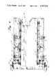
- FIG. 2 is a schematic view of the material take off device of this invention, supplying continuous material to the table top.
- FIG. 3 is a schematic, partial cross-sectional view of the cutting and positioning apparatus of this invention in the open position to receive the fabric.
- FIG. 4 is identical to that of FIG. 3 except that the fabric has been clamped in place for cutting.
- FIG. 5 is a top view of the fabric piece handling device of this invention, looking downwardly to the table top.
- FIG. 6 is a side view of the fabric piece handling device of this invention.
- Preferred embodiments of the invention include all the following and in particular include a tension bar device placed in contact with the fabric in the flow before the fast feed roller device in position to cause the fabric to pass against the bar and provide tension against the fabric generally in the form of a vertical force moment.
- a power device is provided to provide rotation of the various rollers at the relative speeds and at the required time intervals.
- the supply device is generally a large supply roll of a continuous length of fabric to supply material to two rubber nip rolls, equipped to intermittently pull the material at a chosen rate of speed.
- the tension bar device is preferably positioned to cause the web of fabric to pass over the top of a bar having a low sliding coefficient of friction with the fabric and providing an upwardly vertical force on the fabric.
- the fast roller device preferably includes a first fast feed roller continuously rotating counterclockwise, positioned above the fabric in a position to provide surface contact with the fabric.
- a second fast feed roller is continuously rotating clockwise, positioned below the surface of the fabric, such that the fabric is in contact with a substantial portion of its surface.
- the surface contact should be with at least 90 degrees of the radial surface area of the roller.
- the preferred diameter of the feed rollers being at least two inches, up to about ten inches in diameter, more preferably about three to four inches in diameter.
- the coefficient of friction between the fabric and the fast feed roller device is not as critical when the nip roller means is not pulling the material, but is considerably more important when the nip roll device is pulling the material through the fast feed roller device.
- the supply device described above is particularly effective in combination with various additional handling devices, including a cutting device to slice the fabric into pieces, and a piece transfer device to advance the fabric pieces, one after the other, to an operational device to effect a further manufacturing step to the fabric piece.
- This operational device includes the cap making device described above generally described as an apparatus for forming a cap, including advancing the fabric pieces one after the other to an attaching device, a device for rotating the fabric piece about an axis through a central portion of the piece, a device for gripping the central portion of the fabric piece, and a device operative simultaneously and in timed relation to the rotating device, to attach a stretch elastic material to the fabric piece in a predetermined closed curved about the axis of rotation.
- a trimming device is included positioned radially outward of the attaching means and operative in timed relation thereto for removing excess material from the fabric piece.
- the air jetting be directed slightly upwardly at an angle toward the horizontal surface.
- This straightening device coupled with a cutting device and a piece handling device to advance the fabric pieces one after another form a particularly useful combination, and is particularly effective with the cap making device described above.
- the horizontal surface element is preferably a hold-down bar element positioned above the fabric, connected to a clamping means to cause the horizontal surface bar to descend holding the fabric against the table surface, where it may be cut into pieces.
- the blade traveling device for the cutting device is preferably a cutting blade attached to a holder element, sliding on a horizontal rod, first in one direction to cut off one piece of fabric, and then in the opposite direction back to the starting place, cutting off a second piece of fabric, preferably powered by pneumatic equipment.
- the horizontal lengths of the belts of the fabric piece supply device are preferably each angled slightly away from the parallel relationship with each other. In that fashion, as the belts move carrying the fabric along the table surface, the fabric is slightly stretched.
- the surface of the belts in contact with the fabric have a high coefficient of friction with the fabric as compared to the coefficient of friction between the surface of the fabric and the table surface.
- the methods of this invention include pulling on an intermittent basis upon demand from an essentially continuous supply of fabric material, and imposing between the supply source of the fabric and the device accomplishing the pulling, a fast feed roller device including at least two continuously rotating feed rollers, each roller rotating with the flow of the material, the rollers positioned to pressure contact the fabric on a surface area greater than 180 degrees of the combined radial surface of the rollers.
- the feed rollers are operated at a rotating speed faster than the speed of pulling and have a coefficient of friction between the roll surface and the fabric material to allow the roller to slide over the fabric surface.
- the method includes dispensing the fabric on a table surface device, positioned to receive the material and placing a horizontal surface bar element device which provides a horizontal surface above the table over the flow position of the fabric, and directing an air jet providing concentrated air jetting above the fabric material in a generally horizontal direction below the horizontal surface.
- the method also may include clamping the material on both sides of a slot in the table surface, cutting the material along the slot in the table, positioning a pair of continuous belts above the table along the edges of the fabric, along the flow line of the fabric on the table surface, with a horizontal length of belt surface parallel to the table surface, moving the belts intermittently upon demand to the table surface to hold the fabric, and driving the belts while in contact with the fabric to carry the fabric along the table surface.
- cap making device 10 is illustrated as generally embodying the characteristics of the cap making apparatus and method described in the Neill patent referred to above.
- the device is constructed on frame 12 all essentially settling around and directed to table top surface 14.
- Continuous light weight webbing is drawn from supply roll 16, rotating on rod 18.
- Webbing 20 is first drawn under tension bar 22 around and over up to second tension bar 24, around it and downwardly to first fast feed roller 26, partially hidden in FIG. 1, rotating on rod 28.
- FIG. 2 shows the flow of webbing material through this feed apparatus, under roller 26, around it to return at about a 200 degree angle to second fast feed roller 30, passing underneath the roller around over the top and returning backwardly toward the feed angle at more than a 180 degree angle.
- Tension bars 22 and 23 are constructed of one and one-half inch diameter polished stainless steel, allowing the webbing to slide over and around the bars, maintaining a tension on the fabric. These bars may be adjusted as to position and tension to balance the tension against the webbing pull off without increasing the force required to the point of damaging the webbing. Bar 22 may be left off stream as a preferred embodiment.
- Rollers 26 and 30 are each four inch polished stainless steel rollers, each rotating at a radial speed approximately twice that of the speed of take off from roll 16. Roller 26 is positioned in reference to the other rollers such that there is more than 180 degrees of the roller radial surface in contact with the webbing as the roller rotates counterclockwise. Roller 30 is essentially identical to that roller 26, except that it rotates at approximately the same speed in a clockwise fashion, and it is also positioned to be in contact with the webbing over more than 180 degrees of its radial surface. It is preferred that the surface contact between rollers 26 and 30 be more than 90 degrees of the radial surface, more preferably 90 to about 225 degrees of its radial surface, and more preferably 100 to 200 degrees of its radial surface.
- the positioning of these rollers may be such that surface contact may be substantially different and the preferred embodiments may be considered as a total of the surface contact area of the two rollers, preferably being greater than about 180 degrees, more preferably about 180 to about 450 degrees and most preferably 300 degrees to 400 degrees of their combined radial surface areas.
- webbing 20 passes around roller 30, it is directed under, around and over roller 32, which is essentially identical to rollers 26 and 30 as far as construction is concerned.
- feed roller 32 rotates on rod 33 only with and at the same time as material is drawn from roll 16 by nip rolls 34 and 36.
- the rotational speed of roll 32 is preferably slightly faster than that of the actual speed of the web movement, and thus of the radial speed of the nip rollers 34 and 36. It is preferred that the speed of roller 32 be 10 to 50 percent faster than the actual speed of the moving web.
- Standard rubber nip rollers 34 and 36 are of standard design, squeezing webbing 20 and drawing the webbing through the rollers upon demand, and depositing the webbing on the table top surface 14.
- Feed roller 32 is positioned such that webbing 20 is in contact with greater than 180 degrees of the radial surface of the roller and the preferences for contact surface are essentially identical with that of the preferences for rollers 26 and 30.
- webbing 20 is drawn between nip rollers 34 and 36, it is pulled taut against rollers 26, 30 and 32.
- Rollers 26 and 30 are continuously operated at a higher rate of speed than the flow of the webbing, even when the nip rolls are operating at full speed.
- the fabric slides over the surface of rollers 26 and 30 at a speed relative to the surface of the rollers, essentially equal to its actual surface speed.
- Webbing 20 is pulled taut over now rotating roller 32, which is preferably rotating at a slightly higher speed than the speed of the fabric, causing it to slide slightly over the surface of roller 32.
- cap sewing apparatus 38 is constructed to operate above table surface 14 on which webbing 20 is deposited from standard rubber nip rolls 34 and 36. Most of the movement of the various parts other than rotation is by pneumatic pressure, operated through tubes 40 connected to the various elements.
- webbing 20 is deposited on front lip 42, supported on bracket 44 to form slot 46 in front of table surface 14.
- Webbing 20 passes under hold-down arm 48, welded to bracket 50, firmly attached on rod 52 which is twisted by pneumatic cylinder 51 to move arm 48 vertically.
- Positioned on the free end of rod 48 is horizontal surface plate 54 held in a generally horizontal plane above table surface 14.
- air jet 56 positioned to jet air directly under the bottom horizontal surface of plate 54 is angled slightly upwardly toward that plate surface.
- the jetting is directed upwardly about one to five degrees.
- Rear hold-down arm 58 is attached to bracket 60, rotating by rod 62, powered by pneumatic cylinder 63. Both arms 48 and 58 are operated pneumatically and as illustrated in FIG. 4, are capable of rotating downwardly to trap webbing 20 against surface 14 and the top surface of front lip 42. With hold-down member 58 and horizontal plate 54 holding the webbing in place, knife blade 64 held in bracket 66 rides on rod 68. Bracket 66 is powered by a pneumatic line and is essentially shot from one side of the fabric to the other, cutting as it passes one fabric piece off.
- Knife blade 64 is a "V" shaped knife blade having cutting edges on both sides, each at an angle from the vertical of about 30 to 45 degrees, positioned such that the cutting blade bisects the planar surface of table 14 and lip 42. After blade 64 passes one direction, it stays in that position until a second fabric piece is in position to be cut. Bracket 66 is shot back across slot 46 to cut the succeeding fabric piece and returns to its initial position. Although movement of the fabric while in the clamped position is only slight with one pass, cummulative passes in the same direction ultimately force the fabric toward one side of the table. Return cutting in opposite directions as described above eliminates that problem.
- the top view of the fabric piece handling mechanism 70 is illustrated in a top view in FIG. 5, looking down on table top surface 14.
- Brackets 72 and 74 attach to table surface 14 and rigidly hold rod 66 in a horizontal position.
- Arms 78 and 80 fixed to bushings 82 and 84 rotate on rod 66.
- Arms 78 and 80 rigidly support and hold horizontal pulley holding member 86 in a horizontal position above table surface 14.
- Belt 88 rides on main follower pulley 90 and minor follower pulley 92, driven by drive pulley 94.
- Drive pulley 94 is driven by rod 96, passing through bushings in member 86 and extension 98 of rod 76 to upper belt drive pulley 100, driven by belt 102 by lower belt drive pulley 104 turning on rod 106.
- belts 88 and 88' diverge slightly in the horizontal direction as they approach work station 38, the sewing apparatus. Belts 88 and 88' diverge approximately one degree from parallel arrangement and preferably diverge about 1/2 to about five degrees from parallel arrangement.
- Pneumatic cylinders 110 and 112 operate to lift holding member 86, rotating on rod 76 to both lift belt 88 from table surface 14 and to, later in the work cycle, press bottom horizontal belt surface 114 against table surface 14, trapping fabric pieces between the two surfaces and allow them to be moved horizontally along surface 14 to sewing apparatus 38.
- This bottom surface 114 is best illustrated in the side view of FIG. 6.
Landscapes
- Engineering & Computer Science (AREA)
- Textile Engineering (AREA)
- Treatment Of Fiber Materials (AREA)
- Control And Safety Of Cranes (AREA)
- Advancing Webs (AREA)
Priority Applications (7)
| Application Number | Priority Date | Filing Date | Title |
|---|---|---|---|
| US06/416,593 US4545544A (en) | 1982-09-10 | 1982-09-10 | Fabric handling apparatus and method |
| EP83903240A EP0119255B1 (en) | 1982-09-10 | 1983-09-07 | Fabric handling device |
| DE8383903240T DE3379397D1 (en) | 1982-09-10 | 1983-09-07 | Fabric handling device |
| PCT/US1983/001378 WO1984000949A1 (en) | 1982-09-10 | 1983-09-07 | Fabric handling apparatus and method |
| JP58503311A JPS59501783A (ja) | 1982-09-10 | 1983-09-07 | 布取扱い装置及び方法 |
| IT22829/83A IT1169804B (it) | 1982-09-10 | 1983-09-09 | Apparecchiatura e procedimento per la manipolazione di materiale tipo tessuto |
| DK229884A DK161019C (da) | 1982-09-10 | 1984-05-09 | Apparat til haandtering af en kontinuerligt fremfoert tekstilvarebane |
Applications Claiming Priority (1)
| Application Number | Priority Date | Filing Date | Title |
|---|---|---|---|
| US06/416,593 US4545544A (en) | 1982-09-10 | 1982-09-10 | Fabric handling apparatus and method |
Publications (1)
| Publication Number | Publication Date |
|---|---|
| US4545544A true US4545544A (en) | 1985-10-08 |
Family
ID=23650567
Family Applications (1)
| Application Number | Title | Priority Date | Filing Date |
|---|---|---|---|
| US06/416,593 Expired - Fee Related US4545544A (en) | 1982-09-10 | 1982-09-10 | Fabric handling apparatus and method |
Country Status (7)
| Country | Link |
|---|---|
| US (1) | US4545544A (ja) |
| EP (1) | EP0119255B1 (ja) |
| JP (1) | JPS59501783A (ja) |
| DE (1) | DE3379397D1 (ja) |
| DK (1) | DK161019C (ja) |
| IT (1) | IT1169804B (ja) |
| WO (1) | WO1984000949A1 (ja) |
Cited By (16)
| Publication number | Priority date | Publication date | Assignee | Title |
|---|---|---|---|---|
| US4922843A (en) * | 1987-05-14 | 1990-05-08 | Union Special G.M.B.H. | Using a variable speed motor in a tape feed device for a sewing machine |
| US5533820A (en) * | 1993-07-28 | 1996-07-09 | Ambrose; Frederic C. | Keyboard positioning system |
| US5567067A (en) * | 1991-02-01 | 1996-10-22 | Ambrose; Frederic C. | Keyboard positioning system |
| GB2317606A (en) * | 1994-03-04 | 1998-04-01 | Fujitsu Ltd | Roller abrasion evaluation |
| US5908680A (en) * | 1996-03-05 | 1999-06-01 | Minnesota Mining And Manufacturing Company | Replaceable roll covers with repositionable pressure sensitive adhesive |
| US5934663A (en) * | 1994-03-04 | 1999-08-10 | Fujitsu Limited | Rubber rollers for carrying media, and evaluation of their abrasion |
| US5961231A (en) * | 1994-09-16 | 1999-10-05 | Flex-Rest, Llc | Keyboard positioning system |
| US6179602B1 (en) * | 1998-11-20 | 2001-01-30 | Watertown Soles, Inc. | Apparatus and method for delivering an adhesive sheet into a mold |
| US20040234643A1 (en) * | 2002-03-29 | 2004-11-25 | Hurst Kevin W. | Carpet straightening apparatus |
| US20070187026A1 (en) * | 2006-02-01 | 2007-08-16 | The Boeing Company | Fabric handling apparatus and method for composite manufacture |
| EP1985858A1 (de) | 2004-05-14 | 2008-10-29 | Fresenius Medical Care Deutschland GmbH | Rollenpumpe |
| US20080313872A1 (en) * | 2002-03-29 | 2008-12-25 | Hurst Kevin W | Carpet straightening apparatus |
| CN102320486A (zh) * | 2011-09-13 | 2012-01-18 | 浙江恒立数控科技股份有限公司 | 一种带材无损伤卷取张紧机 |
| CN102442569A (zh) * | 2011-09-13 | 2012-05-09 | 浙江恒立数控科技股份有限公司 | 制动型带材无损伤卷取张紧机 |
| CN104261172A (zh) * | 2014-07-30 | 2015-01-07 | 海宁长昆包装有限公司 | 一种bopp薄膜的收卷装置 |
| CN104261172B (zh) * | 2014-07-30 | 2016-11-30 | 海宁长昆包装有限公司 | 一种bopp薄膜的收卷装置 |
Families Citing this family (3)
| Publication number | Priority date | Publication date | Assignee | Title |
|---|---|---|---|---|
| JP2654907B2 (ja) * | 1993-08-18 | 1997-09-17 | 菊地工業株式会社 | 帯状織物の加工処理装置 |
| CN110607611B (zh) * | 2019-09-24 | 2024-04-26 | 强信机械科技(莱州)有限公司 | 一种服装下摆圈缝装置 |
| CN110803563B (zh) * | 2019-10-18 | 2021-02-12 | 桐乡越顺经编有限公司 | 一种用于面料加工的定位裁剪装置 |
Citations (17)
| Publication number | Priority date | Publication date | Assignee | Title |
|---|---|---|---|---|
| US1716375A (en) * | 1927-11-30 | 1929-06-11 | Hood Rubber Co Inc | Feed mechanism for sheet material |
| US2189059A (en) * | 1936-12-19 | 1940-02-06 | American Mach & Foundry | Feeding of web material to cigarette tipping apparatus and other machines |
| US2277514A (en) * | 1940-02-17 | 1942-03-24 | Owens Illinois Can Company | Mechanism for feeding strip stock |
| US2317937A (en) * | 1940-01-19 | 1943-04-27 | Robert H Plass | Apparatus for handling hat fur carrier material or the like |
| US2968982A (en) * | 1957-11-08 | 1961-01-24 | Walter F Cousino | Feeding apparatus |
| US3143016A (en) * | 1960-12-28 | 1964-08-04 | West Virginia Pulp & Paper Co | Webcutting mechanism with forced air work and product transfer means |
| US3216296A (en) * | 1961-03-13 | 1965-11-09 | Warren S D Co | Automatic paper finishing machine |
| US3368771A (en) * | 1965-04-10 | 1968-02-13 | Kalle Ag | Method of and apparatus for unwinding a rolled web of material |
| US3533320A (en) * | 1969-04-04 | 1970-10-13 | Cincinnati Milacron Inc | Material cutting machine having reciprocating cutting blade |
| US3820484A (en) * | 1972-07-26 | 1974-06-28 | Int Paper Co | Cap making apparatus and method |
| US4003411A (en) * | 1973-05-24 | 1977-01-18 | Elitex, Zavody Textilniho Strojirenstvi Generalni Reditalstvi | Device for withdrawing fabrics from looms |
| US4108711A (en) * | 1977-02-23 | 1978-08-22 | B & H Manufacturing Company, Inc. | Label feed |
| US4124156A (en) * | 1977-06-22 | 1978-11-07 | Moore Business Forms, Inc. | Feedback enhanced web feeding apparatus |
| US4182208A (en) * | 1977-09-26 | 1980-01-08 | Polycraft Corporation | Plastic sheet perforating and cutting machine |
| US4189965A (en) * | 1977-09-29 | 1980-02-26 | Rolf Kollann | Revolving cross cutter |
| US4244504A (en) * | 1977-11-11 | 1981-01-13 | J. Bobst & Fils, S.A. | Apparatus for controlling the movement of a web of material continuously delivered to a machine processing the web |
| US4300421A (en) * | 1979-03-23 | 1981-11-17 | Mitsubishi Jukogyo Kabushiki Kaisha | Trim guide device for slitter-scorers |
-
1982
- 1982-09-10 US US06/416,593 patent/US4545544A/en not_active Expired - Fee Related
-
1983
- 1983-09-07 WO PCT/US1983/001378 patent/WO1984000949A1/en active IP Right Grant
- 1983-09-07 DE DE8383903240T patent/DE3379397D1/de not_active Expired
- 1983-09-07 JP JP58503311A patent/JPS59501783A/ja active Pending
- 1983-09-07 EP EP83903240A patent/EP0119255B1/en not_active Expired
- 1983-09-09 IT IT22829/83A patent/IT1169804B/it active
-
1984
- 1984-05-09 DK DK229884A patent/DK161019C/da not_active IP Right Cessation
Patent Citations (17)
| Publication number | Priority date | Publication date | Assignee | Title |
|---|---|---|---|---|
| US1716375A (en) * | 1927-11-30 | 1929-06-11 | Hood Rubber Co Inc | Feed mechanism for sheet material |
| US2189059A (en) * | 1936-12-19 | 1940-02-06 | American Mach & Foundry | Feeding of web material to cigarette tipping apparatus and other machines |
| US2317937A (en) * | 1940-01-19 | 1943-04-27 | Robert H Plass | Apparatus for handling hat fur carrier material or the like |
| US2277514A (en) * | 1940-02-17 | 1942-03-24 | Owens Illinois Can Company | Mechanism for feeding strip stock |
| US2968982A (en) * | 1957-11-08 | 1961-01-24 | Walter F Cousino | Feeding apparatus |
| US3143016A (en) * | 1960-12-28 | 1964-08-04 | West Virginia Pulp & Paper Co | Webcutting mechanism with forced air work and product transfer means |
| US3216296A (en) * | 1961-03-13 | 1965-11-09 | Warren S D Co | Automatic paper finishing machine |
| US3368771A (en) * | 1965-04-10 | 1968-02-13 | Kalle Ag | Method of and apparatus for unwinding a rolled web of material |
| US3533320A (en) * | 1969-04-04 | 1970-10-13 | Cincinnati Milacron Inc | Material cutting machine having reciprocating cutting blade |
| US3820484A (en) * | 1972-07-26 | 1974-06-28 | Int Paper Co | Cap making apparatus and method |
| US4003411A (en) * | 1973-05-24 | 1977-01-18 | Elitex, Zavody Textilniho Strojirenstvi Generalni Reditalstvi | Device for withdrawing fabrics from looms |
| US4108711A (en) * | 1977-02-23 | 1978-08-22 | B & H Manufacturing Company, Inc. | Label feed |
| US4124156A (en) * | 1977-06-22 | 1978-11-07 | Moore Business Forms, Inc. | Feedback enhanced web feeding apparatus |
| US4182208A (en) * | 1977-09-26 | 1980-01-08 | Polycraft Corporation | Plastic sheet perforating and cutting machine |
| US4189965A (en) * | 1977-09-29 | 1980-02-26 | Rolf Kollann | Revolving cross cutter |
| US4244504A (en) * | 1977-11-11 | 1981-01-13 | J. Bobst & Fils, S.A. | Apparatus for controlling the movement of a web of material continuously delivered to a machine processing the web |
| US4300421A (en) * | 1979-03-23 | 1981-11-17 | Mitsubishi Jukogyo Kabushiki Kaisha | Trim guide device for slitter-scorers |
Cited By (22)
| Publication number | Priority date | Publication date | Assignee | Title |
|---|---|---|---|---|
| US4922843A (en) * | 1987-05-14 | 1990-05-08 | Union Special G.M.B.H. | Using a variable speed motor in a tape feed device for a sewing machine |
| US5567067A (en) * | 1991-02-01 | 1996-10-22 | Ambrose; Frederic C. | Keyboard positioning system |
| US5709489A (en) * | 1991-02-01 | 1998-01-20 | Ambrose; Frederic C. | Keyboard positioning system |
| US5533820A (en) * | 1993-07-28 | 1996-07-09 | Ambrose; Frederic C. | Keyboard positioning system |
| GB2317606A (en) * | 1994-03-04 | 1998-04-01 | Fujitsu Ltd | Roller abrasion evaluation |
| US5934663A (en) * | 1994-03-04 | 1999-08-10 | Fujitsu Limited | Rubber rollers for carrying media, and evaluation of their abrasion |
| US5961231A (en) * | 1994-09-16 | 1999-10-05 | Flex-Rest, Llc | Keyboard positioning system |
| US5908680A (en) * | 1996-03-05 | 1999-06-01 | Minnesota Mining And Manufacturing Company | Replaceable roll covers with repositionable pressure sensitive adhesive |
| US6179602B1 (en) * | 1998-11-20 | 2001-01-30 | Watertown Soles, Inc. | Apparatus and method for delivering an adhesive sheet into a mold |
| US7771185B2 (en) | 2002-03-29 | 2010-08-10 | S & K Carpet Specialist, Llc | Carpet straightening apparatus |
| US20080313872A1 (en) * | 2002-03-29 | 2008-12-25 | Hurst Kevin W | Carpet straightening apparatus |
| US7513770B2 (en) * | 2002-03-29 | 2009-04-07 | Hurst Kevin W | Carpet straightening apparatus |
| US20040234643A1 (en) * | 2002-03-29 | 2004-11-25 | Hurst Kevin W. | Carpet straightening apparatus |
| EP1985858A1 (de) | 2004-05-14 | 2008-10-29 | Fresenius Medical Care Deutschland GmbH | Rollenpumpe |
| EP2275681A1 (de) | 2004-05-14 | 2011-01-19 | Fresenius Medical Care Deutschland GmbH | Rollenpumpe |
| US20070187026A1 (en) * | 2006-02-01 | 2007-08-16 | The Boeing Company | Fabric handling apparatus and method for composite manufacture |
| US7601237B2 (en) | 2006-02-01 | 2009-10-13 | The Boeing Company | Fabric handling apparatus and method for composite manufacture |
| CN102320486A (zh) * | 2011-09-13 | 2012-01-18 | 浙江恒立数控科技股份有限公司 | 一种带材无损伤卷取张紧机 |
| CN102442569A (zh) * | 2011-09-13 | 2012-05-09 | 浙江恒立数控科技股份有限公司 | 制动型带材无损伤卷取张紧机 |
| CN102442569B (zh) * | 2011-09-13 | 2015-11-18 | 浙江恒立数控科技股份有限公司 | 制动型带材无损伤卷取张紧机 |
| CN104261172A (zh) * | 2014-07-30 | 2015-01-07 | 海宁长昆包装有限公司 | 一种bopp薄膜的收卷装置 |
| CN104261172B (zh) * | 2014-07-30 | 2016-11-30 | 海宁长昆包装有限公司 | 一种bopp薄膜的收卷装置 |
Also Published As
| Publication number | Publication date |
|---|---|
| JPS59501783A (ja) | 1984-10-25 |
| IT1169804B (it) | 1987-06-03 |
| DE3379397D1 (en) | 1989-04-20 |
| WO1984000949A1 (en) | 1984-03-15 |
| DK161019C (da) | 1991-10-28 |
| DK161019B (da) | 1991-05-21 |
| EP0119255A4 (en) | 1985-09-25 |
| DK229884A (da) | 1984-05-09 |
| IT8322829A1 (it) | 1985-03-09 |
| DK229884D0 (da) | 1984-05-09 |
| IT8322829A0 (it) | 1983-09-09 |
| EP0119255A1 (en) | 1984-09-26 |
| EP0119255B1 (en) | 1989-03-15 |
Similar Documents
| Publication | Publication Date | Title |
|---|---|---|
| US4545544A (en) | Fabric handling apparatus and method | |
| US4470589A (en) | Method and apparatus for feeding and laminating sheets | |
| US3463040A (en) | Machine for cutting sheet materials | |
| US3823629A (en) | Device for cutting pieces of fabric from fabric rolls | |
| US4825622A (en) | Apparatus for selecting and feeding web material | |
| US6223500B1 (en) | Apparatus and method for wrapping compressible articles with a web-like wrapping material | |
| JP2000512967A (ja) | 貯蔵ロールの材料ウエブの外側の層の一部を掴むための方法及び装置 | |
| US3784186A (en) | Method of and apparatus for making pleated and folded articles from a web | |
| US4240336A (en) | Bag making machine | |
| CN115835942A (zh) | 用于切割织造片材织物的设备和方法 | |
| US3728921A (en) | Apparatus for cutting a web into sheets and positioning the sheets | |
| GB2287481A (en) | A process for manufacturing a wax impregnated cloth material | |
| KR102348850B1 (ko) | 부직포 원단 절단장치 | |
| US3540182A (en) | Method of and machine for applying web to an article | |
| US3932259A (en) | Method and apparatus for the manufacture of sheets for holding postage stamps or the like | |
| CN113752721A (zh) | 附加料件加贴装置及带有该装置的装订系统 | |
| US3146649A (en) | Papermaking machine | |
| CA1226511A (en) | Fabric handling apparatus and method | |
| SE424452B (sv) | Sett att maskinellt vika och falla ett fran en tygbana avskiljningsbart tygstycke lengs tva motstaende kanter samt anordning for genomforande av settet | |
| US2850277A (en) | Strip aligning apparatus | |
| CN220974737U (zh) | 服装包纸装置及服装包纸设备 | |
| CN219078633U (zh) | 一种复合薄膜废卷收集系统 | |
| EP1462373A1 (en) | Unit for fixing tear strips on packaging film | |
| JPS5937131B2 (ja) | 金属ウエブ展伸機械 | |
| SU487181A1 (ru) | Лини дл изготовлени искусственного меха на тканевой основе |
Legal Events
| Date | Code | Title | Description |
|---|---|---|---|
| AS | Assignment |
Owner name: FIGGIE INTERNATIONAL, INC., 1000 VIRGINIA CENTER P Free format text: ASSIGNMENT OF ASSIGNORS INTEREST.;ASSIGNORS:ROCKERATH, JOHN L.;BLUST, DALE K.;REEL/FRAME:004389/0426 Effective date: 19820907 |
|
| CC | Certificate of correction | ||
| AS | Assignment |
Owner name: FIGGIE INTERNATIONAL INC. Free format text: MERGER;ASSIGNOR:FIGGIE INTERNATIONAL INC., (MERGED INTO) FIGGIE INTERNATIONAL HOLDINGS INC. (CHANGED TO);REEL/FRAME:004767/0822 Effective date: 19870323 |
|
| FPAY | Fee payment |
Year of fee payment: 4 |
|
| REMI | Maintenance fee reminder mailed | ||
| LAPS | Lapse for failure to pay maintenance fees | ||
| FP | Lapsed due to failure to pay maintenance fee |
Effective date: 19891017 |
|
| STCH | Information on status: patent discontinuation |
Free format text: PATENT EXPIRED DUE TO NONPAYMENT OF MAINTENANCE FEES UNDER 37 CFR 1.362 |