EP0119255B1 - Fabric handling device - Google Patents
Fabric handling device Download PDFInfo
- Publication number
- EP0119255B1 EP0119255B1 EP83903240A EP83903240A EP0119255B1 EP 0119255 B1 EP0119255 B1 EP 0119255B1 EP 83903240 A EP83903240 A EP 83903240A EP 83903240 A EP83903240 A EP 83903240A EP 0119255 B1 EP0119255 B1 EP 0119255B1
- Authority
- EP
- European Patent Office
- Prior art keywords
- fabric
- feed roller
- degrees
- rollers
- roller
- Prior art date
- Legal status (The legal status is an assumption and is not a legal conclusion. Google has not performed a legal analysis and makes no representation as to the accuracy of the status listed.)
- Expired
Links
Images
Classifications
-
- B—PERFORMING OPERATIONS; TRANSPORTING
- B65—CONVEYING; PACKING; STORING; HANDLING THIN OR FILAMENTARY MATERIAL
- B65H—HANDLING THIN OR FILAMENTARY MATERIAL, e.g. SHEETS, WEBS, CABLES
- B65H35/00—Delivering articles from cutting or line-perforating machines; Article or web delivery apparatus incorporating cutting or line-perforating devices, e.g. adhesive tape dispensers
- B65H35/0006—Article or web delivery apparatus incorporating cutting or line-perforating devices
-
- B—PERFORMING OPERATIONS; TRANSPORTING
- B65—CONVEYING; PACKING; STORING; HANDLING THIN OR FILAMENTARY MATERIAL
- B65H—HANDLING THIN OR FILAMENTARY MATERIAL, e.g. SHEETS, WEBS, CABLES
- B65H20/00—Advancing webs
- B65H20/02—Advancing webs by friction roller
-
- B—PERFORMING OPERATIONS; TRANSPORTING
- B65—CONVEYING; PACKING; STORING; HANDLING THIN OR FILAMENTARY MATERIAL
- B65H—HANDLING THIN OR FILAMENTARY MATERIAL, e.g. SHEETS, WEBS, CABLES
- B65H20/00—Advancing webs
- B65H20/02—Advancing webs by friction roller
- B65H20/04—Advancing webs by friction roller to effect step-by-step advancement of web
-
- B—PERFORMING OPERATIONS; TRANSPORTING
- B65—CONVEYING; PACKING; STORING; HANDLING THIN OR FILAMENTARY MATERIAL
- B65H—HANDLING THIN OR FILAMENTARY MATERIAL, e.g. SHEETS, WEBS, CABLES
- B65H23/00—Registering, tensioning, smoothing or guiding webs
- B65H23/04—Registering, tensioning, smoothing or guiding webs longitudinally
- B65H23/26—Registering, tensioning, smoothing or guiding webs longitudinally by transverse stationary or adjustable bars or rollers
-
- D—TEXTILES; PAPER
- D06—TREATMENT OF TEXTILES OR THE LIKE; LAUNDERING; FLEXIBLE MATERIALS NOT OTHERWISE PROVIDED FOR
- D06H—MARKING, INSPECTING, SEAMING OR SEVERING TEXTILE MATERIALS
- D06H7/00—Apparatus or processes for cutting, or otherwise severing, specially adapted for the cutting, or otherwise severing, of textile materials
-
- B—PERFORMING OPERATIONS; TRANSPORTING
- B65—CONVEYING; PACKING; STORING; HANDLING THIN OR FILAMENTARY MATERIAL
- B65H—HANDLING THIN OR FILAMENTARY MATERIAL, e.g. SHEETS, WEBS, CABLES
- B65H2301/00—Handling processes for sheets or webs
- B65H2301/40—Type of handling process
- B65H2301/41—Winding, unwinding
- B65H2301/414—Winding
- B65H2301/4148—Winding slitting
Definitions
- U.S. Patent No. 2,189,059 granted to G. Dears- ley discloses a device for continuously feeding web material from a supply reel, wherein a single fast roller is employed to provide a slipping friction drive for drawing the web from the supply.
- the disclosure of this prior patent is acknowledged in the preamble of claim 1.
- a high coefficient of friction is utilized to draw the web from its supply roll and a spring control is needed to bring the web into contact with the drive roll.
- the present invention uses drive rolls with a low coefficient of friction and eliminates the necessity of springs or stoppage of the supply of fabric.
- Two continuous rotating rollers which receive a web from a supply are shown from U.S. 3,216,296 granted to G. For- rester, the rollers providing contact with the web over more than half of the peripheral area of the rollers. However, such rollers are used to provide a retarding or braking function.
- a particular embodiment of the apparatus includes the intermittent second feed roller, positioned to contact the fabric after it leaves the fast feed roller device.
- the second feed roller rotates at the time inteval and concurrently with the nip roll device with the flow of material.
- the contact between the roller and the material has a surface area greater than about 90 percent of the roller's radial surface, with a coefficient of friction between this roller and the fabric to allow the roller to slide over the fabric.
- the surface speed of this second feed roller is faster than the nip roll, but less than the surface speed of the fast feed roller device.
- the preferred range of speeds is that the fast feed roller device rotate at about 50 percent or more faster than the nip roll, and more preferably about 50 to about 200 percent faster.
- the second feed roller is preferably rotated at about 10 to about 50 percent faster than the nip roll.
Landscapes
- Engineering & Computer Science (AREA)
- Textile Engineering (AREA)
- Treatment Of Fiber Materials (AREA)
- Control And Safety Of Cranes (AREA)
- Advancing Webs (AREA)
Abstract
Description
- This invention relates to a device for supplying a continuous feed of fabric material and handling the material.
- By the term "fabric", as used through the specifications and the claims, it is intended that that term include both woven and nonwoven fabric, webbing material, film, such as plastic film, reinforced and unreinforced, such as polyethylene film, and sheet materials, all supplied in continuous form.
- This invention is particularly useful for supplying nonwoven web fabric in an apparatus and method such as that used to produce caps as described in United States Patent No. 3,820,484 to William M. Neill and George A. Burt, Jr. of June 28,1974, which illustrates utility of the invention.
- A paricular problem in continuous manufacturing operations utilizing pieces of fabric, is to handle the material from large rolls, which are an essentially inexhaustable source, cut the fabric into pieces and move them to a subsequent work station where later manufacturing steps are taken, such as that of the Neill patent described hereinabove.
- In particular, the large rolls of fabric are extremely heavy, are not necessarily balanced or of even tension, and in any case vary substantially as to the pulling power necessary to pull the fabric off the roll as the amount of fabric remaining on the roll decreases. These large rolls have a tendency to be harder to get started rotating and then difficult to stop when the material is being pulled off on an intermittent basis. Thus, an uneven supply of the continuous fabric to a cutter is a problem that had not been solved.
- In addition, certain types of fabric and in particular the nonwoven, lightly structured, almost diaphanous material used in the Neill patent is difficult to handle to maintain a smooth uniform positioning during the cutting process and later handling processing of the cut pieces. These problems as well as others illustrated later, constituted a great need to allow the developments of the Neill patent and like continuous processes to be fully developed into an operational production apparatus and method.
- U.S. Patent No. 2,189,059 granted to G. Dears- ley discloses a device for continuously feeding web material from a supply reel, wherein a single fast roller is employed to provide a slipping friction drive for drawing the web from the supply. The disclosure of this prior patent is acknowledged in the preamble of claim 1. In this prior patent a high coefficient of friction is utilized to draw the web from its supply roll and a spring control is needed to bring the web into contact with the drive roll. The present invention uses drive rolls with a low coefficient of friction and eliminates the necessity of springs or stoppage of the supply of fabric. Two continuous rotating rollers which receive a web from a supply are shown from U.S. 3,216,296 granted to G. For- rester, the rollers providing contact with the web over more than half of the peripheral area of the rollers. However, such rollers are used to provide a retarding or braking function.
- The invention includes a device for continuous supply of fabric as defined in claim 1.
- A particular embodiment of the apparatus includes the intermittent second feed roller, positioned to contact the fabric after it leaves the fast feed roller device. The second feed roller rotates at the time inteval and concurrently with the nip roll device with the flow of material. The contact between the roller and the material has a surface area greater than about 90 percent of the roller's radial surface, with a coefficient of friction between this roller and the fabric to allow the roller to slide over the fabric. Preferably, the surface speed of this second feed roller is faster than the nip roll, but less than the surface speed of the fast feed roller device. The preferred range of speeds is that the fast feed roller device rotate at about 50 percent or more faster than the nip roll, and more preferably about 50 to about 200 percent faster. Similarly, the second feed roller is preferably rotated at about 10 to about 50 percent faster than the nip roll.
- It is an object of this invention to provide an apparatus with the capability of drawing fabric from a continuous source in such a fashion to provide to nip rolls, a uniform supply, despite the varying force required to draw on the continuous supply.
- An additional object of this invention is to provide a take off system from a continuous roll of fabric that does not impart substantial stretching and stress to the fabric, which might cause failure or distortion of the fabric structure.
- It is a further object of this invention to provide a take off device to remove light weight fragile webs from large rolls without stretching or destroying the webs and supplying the material on a continuous and standardized condition.
- It is a further object of this invention to provide an apparatus which will position and move the fabric past the nip rolls, causing it to spread evenly and uniformly over a transport table surface.
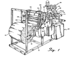
- Fig. 1 is a perspective view of the material handling machine, suppling fabric pieces to a cap making apparatus and comprising the material take off device of this invention.
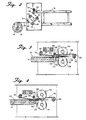
- Fig. 2 is a schematic view of the material take off device of this invention, supplying continuous material to the table top of the cap making apparatus.
- Figs. 3-6 are further views illustrative of the cap making apparatus with which the material handling device of the invention may be used,
- Fig. 3 being a schematic, partial cross-sectional view of a cutting and positioning apparatus of said cap making apparatus in the open position to receive the fabric.
- Fig. 4 is identical to that of Fig. 3 except that the fabric has been clamped in place for cutting.
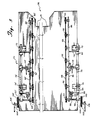
- Fig. 5 is a top view of a fabric piece handling device, looking downwardly to the table top.
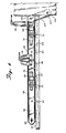
- Fig. 6 is a side view of the fabric piece handling device.
- Preferred embodiments of the invention include all the following and in particular include a tension bar device placed in contact with the fabric in the flow before the fast feed roller device in position to cause the fabric to pass against the bar and provide tension against the fabric generally in the form of a vertical force moment. A pwer device is provided to provide rotation of the various rollers at the relative speeds and at the required time intervals. The supply device is generally a large supply roll of a continuous length of fabric to supply material to two rubber nip rolls, equipped to intermittently pull the material at a chosen rate of speed. The tension bar device is preferably positioned to cause the web of fabric to pass over the top of a bar having a low sliding coefficient of friction with the fabric and providing an upwardly vertical force on the fabric. If additional tension is required, a pair of tension bars may be utilized wherein the fabric is passed over one and under the other to provide substantially increased surface area of sliding frction to increase the tension. The fast roller device preferably includes a first past feed roller continously rotating counterclockwise, positioned above the fabric in a position to provide surface contact with the fabric. A second fast feed roller is continuously rotating clockwise, positioned below the surface of the fabric, such that the fabric is in contact with a substantial portion of its surface. In each case, the surface contact should be with at least 90 degrees of the radial surface area of the roller. The preferred diameter of the feed rollers being at least 5cm (twojnches), up to about 25cm (ten inches) in diameter, more preferably about 7.5 to 10 cm (three to four inches) in diameter. The coefficient of friction between the fabric and the fast feed roller device is not as critical when the nip roller means is not pulling the material, but is considerably more important when the nip roll device is pulling the material through the fast feed roller device.
- The supply device described above is particularly effective in combination with various additional handling devices.
- Referring now to Fig. 1,
cap making device 10 is illustrated as generally embodying the characteristics of the cap making apparatus and method described in the Neill patent referred to above. The device is constructed onframe 12 all essentially settling around and directed totable top surface 14. Continuous light weight webbing is drawn fromsupply roll 16, rotating onrod 18.Webbing 20 is first drawn undertension bar 22 around and over up tosecond tension bar 24, around it and downwardly to firstfast feed roller 26, partially hidden in Fig. 1, rotating onrod 28. In this area, it is useful to refer to te schematic drawing of Fig. 2 showing the flow of webbing material through this feed apparatus, under roller . 26, around it to return at about a 200 degree angle to secondfast feed roller 30, passing underneath the roller around over the top and returning backwardly toward the feed angle at more than a 180 degree angle.Tension bars Bar 22 may be left off stream as a preferred embodiment. -
Rollers roll 16.Roller 26 is positioned in reference to the other rollers such that there is more than 180 degrees of the roller radial surface in contact with the webbing as the roller rotates counterclockwise.Roller 30 is essentially identical to thatroller 26, except that it rotates at approximately the same speed in a clockwise fashion, and it is also positioned to be in contact with the webbing over more thn 180 degrees of its radial surface. It is preferred that the surface contact betweenrollers - After webbing 20 passes around
roller 30, it is directed under, around and overroller 32, which is essentially identical torollers feed roller 32 rotates onrod 33 only with and at the same time as material is drawn fromroll 16 bynip rolls roll 32 is preferably slightly faster than that of the actual speed of the web movement, and thus of the radial speed of thenip rollers roller 32 be 10 to 50 percent faster than the actual speed of the moving web. Standardrubber nip rollers webbing 20 and drawing the webbing through the rollers upon demand, and depositing the webbing on thetable top surface 14. Feedroller 32 is positioned such thatwebbing 20 is in contact with greater than 180 degrees of the radial surface of the roller and the preferences for contact surface essentially identical with that of the preferences forrollers webbing 20 is drawn betweennip rollers rollers Rollers rollers Webbing 20 is pulled taut over now rotatingroller 32, which is preferably rotating at a slightly higher speed than the speed of the fabric, causing it to side slightly over the surface ofroller 32. - Returning now to Fig. 1
cap sewing apparatus 38 is constructed to operate abovetable surface 14 on whichwebbing 20 is deposited from standard rubber niprolls tubes 40 connected to the various elements. Referring also to Fig. 3, webbing 20 is deposited onfront lip 42, supported onbracket 44 to formslot 46 is front oftable surface 14.Webbing 20 passes under hold-downarm 48, welded tobracket 50, firmly attached onrod 52 which is twisted by pneumatic cylinder to movearm 48 vertically. Positioned on the free end ofrod 48 ishorizontal surface plate 54 held in a generally horizontal plane abovetable surface 14. Although not quite pictured,air jet 56 positioned to jet air directly under the bottom horizontal surface ofplate 54 is angled slightly upwardly toward that plate surface. Preferably, the jetting is directed upwardly about 1 to 5 degrees. Rear hold-downarm 58 is attached tobracket 60, rotating byrod 62, powered bypneumatic cylinder 63. Botharms trap webbing 20 againstsurface 14 and the top surface offront lip 42. With hold-down member 58 andhorizontal plate 54 holding the webbing in place,knife blade 64 held inbracket 66 rides onrod 68.Bracket 66 is powered by a pneumatic line and is essentially shot from one side of the fabric to the other cutting as it passes one fabric piece off.Knife blade 64 is a "V" shaped knife blade having cutting edges on both sides, each at an angle from the vertical of about 30 to 45 degrees, positioned such that the cutting blade bisects the planar surface of table 14 andlip 42. Afterblade 64 passes one direction, it stays in the position until a second fabric piece is in position to be cut.Bracket 66 is shot back acrossslot 46 to cut the succeeding fabric piece and returns to its initial position. Although movement of the fabric while in the clamped position is only slight with one pass, commulative passes in the same direction ultimately force the fabric toward one side of the table. Return cutting in opposite directions as described above eliminates that problem. The top view of the fabricpiece handling mechanism 70 is illustrated in a top view in Fig. 5, looking down on tabletop surface 14. The mechanisms on opposite sides oftable 14 are essentially mirror images of each other and for the purposes of simplicity, only one side will be described, the other side being designated with a "prime". It should be recognized that essentially identical parts are positioned across from the described parts to form the dual structure, handling the fabric pieces along their outside edges along the flow pattern of the process.Brackets surface 14 and rigidly holdrod 76 in a horizontal position.Arms bushings rod 76.Arms pulley holding member 86 in a horizontal position abovetable surface 14.Belt 88 rides onmain follower pulley 90 andminor follower pulley 92, driven bydrive pulley 94. Drivepulley 94 is driven byrod 96, passing through bushings inmember 86 andextension 98 ofrod 76 to upperbelt drive pulley 100, driven bybelt 102 by lowerbelt drive pulley 104 turning onrod 106. Although it may not be apparent from Fig. 5,belts 88 and 88' diverge slightly in the horizontal direction as they approachwork station 38, the sewing apparatus.Belts 88 and 88' diverge approximately 1 degree from parallel arrangement and preferably diverge about 1/2 to about 5 degrees from parallel arrangement.Pneumatic cylinders member 86, rotating onrod 76 to bothlift belt 88 fromtable surface 14 and to, later in the work cycle, press bottomhorizontal belt surface 114 againsttable surface 14, trapping fabric pieces between the two surfaces and allow them to be moved horizontally along surface14to sewing apparatus 38. thisbottom surface 114 is best illustrated in the side view of Fig. 6.
Claims (6)
Applications Claiming Priority (2)
| Application Number | Priority Date | Filing Date | Title |
|---|---|---|---|
| US06/416,593 US4545544A (en) | 1982-09-10 | 1982-09-10 | Fabric handling apparatus and method |
| US416593 | 1982-09-10 |
Publications (3)
| Publication Number | Publication Date |
|---|---|
| EP0119255A1 EP0119255A1 (en) | 1984-09-26 |
| EP0119255A4 EP0119255A4 (en) | 1985-09-25 |
| EP0119255B1 true EP0119255B1 (en) | 1989-03-15 |
Family
ID=23650567
Family Applications (1)
| Application Number | Title | Priority Date | Filing Date |
|---|---|---|---|
| EP83903240A Expired EP0119255B1 (en) | 1982-09-10 | 1983-09-07 | Fabric handling device |
Country Status (7)
| Country | Link |
|---|---|
| US (1) | US4545544A (en) |
| EP (1) | EP0119255B1 (en) |
| JP (1) | JPS59501783A (en) |
| DE (1) | DE3379397D1 (en) |
| DK (1) | DK161019C (en) |
| IT (1) | IT1169804B (en) |
| WO (1) | WO1984000949A1 (en) |
Cited By (1)
| Publication number | Priority date | Publication date | Assignee | Title |
|---|---|---|---|---|
| CN110803563A (en) * | 2019-10-18 | 2020-02-18 | 桐乡越顺经编有限公司 | Positioning and cutting device for fabric processing |
Families Citing this family (16)
| Publication number | Priority date | Publication date | Assignee | Title |
|---|---|---|---|---|
| DE3716148C1 (en) * | 1987-05-14 | 1988-12-15 | Union Special Gmbh | Tape feed device on a sewing machine |
| AU1339992A (en) * | 1991-02-01 | 1992-09-07 | Frederic C. Ambrose | Keyboard positioning system |
| US5405204A (en) * | 1992-02-03 | 1995-04-11 | Ambrose; Frederic C. | Keyboard positioning system |
| JP2654907B2 (en) * | 1993-08-18 | 1997-09-17 | 菊地工業株式会社 | Processing equipment for strip fabric |
| JPH07243436A (en) * | 1994-03-04 | 1995-09-19 | Fujitsu Ltd | Medium transferring rubber roller and its abrasion estimation |
| GB2317606A (en) * | 1994-03-04 | 1998-04-01 | Fujitsu Ltd | Roller abrasion evaluation |
| US5961231A (en) * | 1994-09-16 | 1999-10-05 | Flex-Rest, Llc | Keyboard positioning system |
| US5908680A (en) * | 1996-03-05 | 1999-06-01 | Minnesota Mining And Manufacturing Company | Replaceable roll covers with repositionable pressure sensitive adhesive |
| US6179602B1 (en) * | 1998-11-20 | 2001-01-30 | Watertown Soles, Inc. | Apparatus and method for delivering an adhesive sheet into a mold |
| US7771185B2 (en) * | 2002-03-29 | 2010-08-10 | S & K Carpet Specialist, Llc | Carpet straightening apparatus |
| US6800235B1 (en) * | 2002-03-29 | 2004-10-05 | S & K Flooring | Carpet straightening apparatus |
| DK1763636T3 (en) | 2004-05-14 | 2008-12-01 | Fresenius Medical Care De Gmbh | Roll pump |
| US7601237B2 (en) * | 2006-02-01 | 2009-10-13 | The Boeing Company | Fabric handling apparatus and method for composite manufacture |
| CN102320486B (en) * | 2011-09-13 | 2013-07-17 | 浙江恒立数控科技股份有限公司 | Belt material non-destructive coiling tensioner |
| CN102442569B (en) * | 2011-09-13 | 2015-11-18 | 浙江恒立数控科技股份有限公司 | Braked strip zero damage reeling tensioning device |
| CN110607611B (en) * | 2019-09-24 | 2024-04-26 | 强信机械科技(莱州)有限公司 | Clothing hem girth device |
Family Cites Families (17)
| Publication number | Priority date | Publication date | Assignee | Title |
|---|---|---|---|---|
| US1716375A (en) * | 1927-11-30 | 1929-06-11 | Hood Rubber Co Inc | Feed mechanism for sheet material |
| US2189059A (en) * | 1936-12-19 | 1940-02-06 | American Mach & Foundry | Feeding of web material to cigarette tipping apparatus and other machines |
| US2317937A (en) * | 1940-01-19 | 1943-04-27 | Robert H Plass | Apparatus for handling hat fur carrier material or the like |
| US2277514A (en) * | 1940-02-17 | 1942-03-24 | Owens Illinois Can Company | Mechanism for feeding strip stock |
| US2968982A (en) * | 1957-11-08 | 1961-01-24 | Walter F Cousino | Feeding apparatus |
| US3143016A (en) * | 1960-12-28 | 1964-08-04 | West Virginia Pulp & Paper Co | Webcutting mechanism with forced air work and product transfer means |
| US3216296A (en) * | 1961-03-13 | 1965-11-09 | Warren S D Co | Automatic paper finishing machine |
| NL140809B (en) * | 1965-04-10 | 1974-01-15 | Kalle Ag | DEVICE FOR MAINTAINING JOB TENSION IN A REPLACEMENT MATERIAL JOB. |
| US3573857A (en) * | 1969-04-04 | 1971-04-06 | Cincinnati Milacron Inc | Reciprocating cutting blade |
| US3820484A (en) * | 1972-07-26 | 1974-06-28 | Int Paper Co | Cap making apparatus and method |
| CS163087B1 (en) * | 1973-05-24 | 1975-07-31 | ||
| US4108711A (en) * | 1977-02-23 | 1978-08-22 | B & H Manufacturing Company, Inc. | Label feed |
| US4124156A (en) * | 1977-06-22 | 1978-11-07 | Moore Business Forms, Inc. | Feedback enhanced web feeding apparatus |
| US4182208A (en) * | 1977-09-26 | 1980-01-08 | Polycraft Corporation | Plastic sheet perforating and cutting machine |
| DE2743801C3 (en) * | 1977-09-29 | 1980-04-24 | Jagenberg-Werke Ag, 4000 Duesseldorf | Rotary sheeter |
| CH618660A5 (en) * | 1977-11-11 | 1980-08-15 | Bobst Fils Sa J | |
| JPS5850999Y2 (en) * | 1979-03-23 | 1983-11-21 | 三菱重工業株式会社 | Trim guide device of Slituta scorer |
-
1982
- 1982-09-10 US US06/416,593 patent/US4545544A/en not_active Expired - Fee Related
-
1983
- 1983-09-07 EP EP83903240A patent/EP0119255B1/en not_active Expired
- 1983-09-07 DE DE8383903240T patent/DE3379397D1/en not_active Expired
- 1983-09-07 WO PCT/US1983/001378 patent/WO1984000949A1/en active IP Right Grant
- 1983-09-07 JP JP58503311A patent/JPS59501783A/en active Pending
- 1983-09-09 IT IT22829/83A patent/IT1169804B/en active
-
1984
- 1984-05-09 DK DK229884A patent/DK161019C/en not_active IP Right Cessation
Cited By (2)
| Publication number | Priority date | Publication date | Assignee | Title |
|---|---|---|---|---|
| CN110803563A (en) * | 2019-10-18 | 2020-02-18 | 桐乡越顺经编有限公司 | Positioning and cutting device for fabric processing |
| CN110803563B (en) * | 2019-10-18 | 2021-02-12 | 桐乡越顺经编有限公司 | Positioning and cutting device for fabric processing |
Also Published As
| Publication number | Publication date |
|---|---|
| DE3379397D1 (en) | 1989-04-20 |
| EP0119255A4 (en) | 1985-09-25 |
| DK229884D0 (en) | 1984-05-09 |
| IT8322829A1 (en) | 1985-03-09 |
| IT8322829A0 (en) | 1983-09-09 |
| WO1984000949A1 (en) | 1984-03-15 |
| JPS59501783A (en) | 1984-10-25 |
| EP0119255A1 (en) | 1984-09-26 |
| US4545544A (en) | 1985-10-08 |
| DK161019C (en) | 1991-10-28 |
| DK161019B (en) | 1991-05-21 |
| DK229884A (en) | 1984-05-09 |
| IT1169804B (en) | 1987-06-03 |
Similar Documents
| Publication | Publication Date | Title |
|---|---|---|
| EP0119255B1 (en) | Fabric handling device | |
| US4470589A (en) | Method and apparatus for feeding and laminating sheets | |
| US4825622A (en) | Apparatus for selecting and feeding web material | |
| US4489900A (en) | Apparatus for automatically cutting and winding sheet material | |
| US6223500B1 (en) | Apparatus and method for wrapping compressible articles with a web-like wrapping material | |
| US5235829A (en) | Roller dyeing machine for surface impregnating hides and similar products | |
| CA3084008C (en) | Banding and packaging device | |
| US3784186A (en) | Method of and apparatus for making pleated and folded articles from a web | |
| US5447296A (en) | Cloth spreading system | |
| CN115835942A (en) | Apparatus and method for cutting woven sheet fabric | |
| US3720383A (en) | Timed supply roll braking | |
| US3728921A (en) | Apparatus for cutting a web into sheets and positioning the sheets | |
| GB2287481A (en) | A process for manufacturing a wax impregnated cloth material | |
| US3540182A (en) | Method of and machine for applying web to an article | |
| EP0781721B1 (en) | Machine for laying out laminar products | |
| EP1462373A1 (en) | Unit for fixing tear strips on packaging film | |
| WO1991012176A1 (en) | Improvements in or relating to over-wrapping apparatus for packaging machines | |
| CA1226511A (en) | Fabric handling apparatus and method | |
| US4056023A (en) | Single web sheet cutter and stacker | |
| US4824039A (en) | Apparatus for applying a paper web to the underside of a roll-making drum | |
| EP1123889B1 (en) | Block formation system and method for controlling the folding of a block | |
| JPS63300051A (en) | Roll elongation device | |
| JPS5937131B2 (en) | metal web stretching machine | |
| JPH0364419B2 (en) | ||
| JPS62135144A (en) | Rolled wet towel molding method and rolled wet towel |
Legal Events
| Date | Code | Title | Description |
|---|---|---|---|
| PUAI | Public reference made under article 153(3) epc to a published international application that has entered the european phase |
Free format text: ORIGINAL CODE: 0009012 |
|
| AK | Designated contracting states |
Designated state(s): CH DE FR GB LI |
|
| 17P | Request for examination filed |
Effective date: 19840830 |
|
| 17Q | First examination report despatched |
Effective date: 19860416 |
|
| RAP1 | Party data changed (applicant data changed or rights of an application transferred) |
Owner name: FIGGIE INTERNATIONAL INC. (DELAWARE CORPORATION) |
|
| GRAA | (expected) grant |
Free format text: ORIGINAL CODE: 0009210 |
|
| AK | Designated contracting states |
Kind code of ref document: B1 Designated state(s): CH DE FR GB LI |
|
| REF | Corresponds to: |
Ref document number: 3379397 Country of ref document: DE Date of ref document: 19890420 |
|
| ET | Fr: translation filed | ||
| PLBE | No opposition filed within time limit |
Free format text: ORIGINAL CODE: 0009261 |
|
| STAA | Information on the status of an ep patent application or granted ep patent |
Free format text: STATUS: NO OPPOSITION FILED WITHIN TIME LIMIT |
|
| 26N | No opposition filed | ||
| PGFP | Annual fee paid to national office [announced via postgrant information from national office to epo] |
Ref country code: CH Payment date: 19901018 Year of fee payment: 8 Ref country code: FR Payment date: 19901018 Year of fee payment: 8 |
|
| PGFP | Annual fee paid to national office [announced via postgrant information from national office to epo] |
Ref country code: DE Payment date: 19901023 Year of fee payment: 8 |
|
| PGFP | Annual fee paid to national office [announced via postgrant information from national office to epo] |
Ref country code: GB Payment date: 19901105 Year of fee payment: 8 |
|
| PG25 | Lapsed in a contracting state [announced via postgrant information from national office to epo] |
Ref country code: GB Effective date: 19910907 |
|
| PG25 | Lapsed in a contracting state [announced via postgrant information from national office to epo] |
Ref country code: LI Effective date: 19910930 Ref country code: CH Effective date: 19910930 |
|
| GBPC | Gb: european patent ceased through non-payment of renewal fee | ||
| PG25 | Lapsed in a contracting state [announced via postgrant information from national office to epo] |
Ref country code: FR Effective date: 19920529 |
|
| REG | Reference to a national code |
Ref country code: CH Ref legal event code: PL |
|
| PG25 | Lapsed in a contracting state [announced via postgrant information from national office to epo] |
Ref country code: DE Effective date: 19920602 |
|
| REG | Reference to a national code |
Ref country code: FR Ref legal event code: ST |