US4349948A - Method for manufacturing metal casings for accessories and particularly gate valves - Google Patents
Method for manufacturing metal casings for accessories and particularly gate valves Download PDFInfo
- Publication number
- US4349948A US4349948A US06/119,506 US11950680A US4349948A US 4349948 A US4349948 A US 4349948A US 11950680 A US11950680 A US 11950680A US 4349948 A US4349948 A US 4349948A
- Authority
- US
- United States
- Prior art keywords
- forming
- collars
- casing
- plate
- tool
- Prior art date
- Legal status (The legal status is an assumption and is not a legal conclusion. Google has not performed a legal analysis and makes no representation as to the accuracy of the status listed.)
- Expired - Lifetime
Links
Images


Classifications
-
- F—MECHANICAL ENGINEERING; LIGHTING; HEATING; WEAPONS; BLASTING
- F16—ENGINEERING ELEMENTS AND UNITS; GENERAL MEASURES FOR PRODUCING AND MAINTAINING EFFECTIVE FUNCTIONING OF MACHINES OR INSTALLATIONS; THERMAL INSULATION IN GENERAL
- F16K—VALVES; TAPS; COCKS; ACTUATING-FLOATS; DEVICES FOR VENTING OR AERATING
- F16K27/00—Construction of housing; Use of materials therefor
- F16K27/10—Welded housings
- F16K27/105—Welded housings for gate valves
-
- B—PERFORMING OPERATIONS; TRANSPORTING
- B21—MECHANICAL METAL-WORKING WITHOUT ESSENTIALLY REMOVING MATERIAL; PUNCHING METAL
- B21K—MAKING FORGED OR PRESSED METAL PRODUCTS, e.g. HORSE-SHOES, RIVETS, BOLTS OR WHEELS
- B21K1/00—Making machine elements
- B21K1/20—Making machine elements valve parts
- B21K1/24—Making machine elements valve parts valve bodies; valve seats
-
- B—PERFORMING OPERATIONS; TRANSPORTING
- B23—MACHINE TOOLS; METAL-WORKING NOT OTHERWISE PROVIDED FOR
- B23P—METAL-WORKING NOT OTHERWISE PROVIDED FOR; COMBINED OPERATIONS; UNIVERSAL MACHINE TOOLS
- B23P15/00—Making specific metal objects by operations not covered by a single other subclass or a group in this subclass
- B23P15/001—Making specific metal objects by operations not covered by a single other subclass or a group in this subclass valves or valve housings
-
- Y—GENERAL TAGGING OF NEW TECHNOLOGICAL DEVELOPMENTS; GENERAL TAGGING OF CROSS-SECTIONAL TECHNOLOGIES SPANNING OVER SEVERAL SECTIONS OF THE IPC; TECHNICAL SUBJECTS COVERED BY FORMER USPC CROSS-REFERENCE ART COLLECTIONS [XRACs] AND DIGESTS
- Y10—TECHNICAL SUBJECTS COVERED BY FORMER USPC
- Y10T—TECHNICAL SUBJECTS COVERED BY FORMER US CLASSIFICATION
- Y10T29/00—Metal working
- Y10T29/49—Method of mechanical manufacture
- Y10T29/49405—Valve or choke making
- Y10T29/49412—Valve or choke making with assembly, disassembly or composite article making
- Y10T29/49414—Joining plural semi-circular components
Definitions
- This invention relates to accessory casings in general and, in particular, to a new and useful valve casing and method of manufacturing said valve casing.
- each of the casing parts is provided with an outwardly projecting flange-like rim to which a pipe connection is welded.
- a pipe connection is welded to each of the rimmed-out portions, with the two pipe connection ends facing each other, to which valve seat rings may be welded, forming guides and the valve seat for a shutoff member and, in the case under consideration, a gate.
- Such a prior art gate valve casing has the disadvantage that the inside pipe connections providing the valve seat faces are secured by welds which cannot be inspected ultrasonically or radiographically. Such gate valve casings are, therefore, unusable in instances where particular safety regulations are to be met, for example, in nuclear power plants.
- gate valve casings manufactured in accordance with the prior art method, particularly large gate valves may be very expensive.
- the present invention is directed to a method of the above-mentioned kind which eliminates the disadvantages of the prior art methods and avoids inside welds, while permitting simple manufacture and ultrasonic and radiographic inspections.
- the invention is further directed to a device for carrying out the method, primarily for manufacturing gate-valve casings, which is simple in construction and makes it possible to manufacture even gate valve casings of very large nominal widths.
- the casing parts to be assembled to a casing, preferably for gate valves, may be manufactured, in accordance with the invention, in a variety of advantageous ways.
- a flat plate blank may be provided with a bored- or burned-through hole of a relatively small diameter.
- the wall portions of this hole or bore are then deformed by suitable tools, particularly rollers, so as to produce flange-like collars which extend in opposite directions perpendicularly to the surface of the blank.
- suitable tools particularly rollers
- the blank with the hole bordered by rimmed-out collars and enlarged to the diameter of the pipe connection to be later welded on from the outside is placed into suitable forming tools, particularly into a press, where the still flat portions of the blank are worked to the shape of the casing part.
- upper and lower dies are applied to both sides of the blank prior to working it to shape, with the dies supporting and holding the collars and the surface portions in that area, preferably all around. This may be followed by a further forming and/or overforming of portions of the collars. It is possible, for example, to further form or overform the free end of the collar ridge facing the interior of the casing as desired, for example, to press this collar crest flat, so that a suitable lining or valve seat part may later be applied thereto.
- finish-formed casing parts are then removed from the forming tools.
- a variation of the inventive method starts from a flat blank with a through-hole of relatively small diameter and forming the blank, in a suitable tool, particularly a press, immediately to the shape of the casing part.
- the flange-like collars are formed either within the casing-forming tool, for example, in an upsetting or rolling operation, or the upsetting or rolling of the collars is performed subsequently, outside of the tool in which the casings have been formed. It is also possible, however, to press the blanks to casing parts and to make the holes at the same time, and to form the flange-like collars, for example, by rolling or upsetting, simultaneously with, or with some delay after, the shaping of the casing part.
- a particular advantage of the inventive method is that inside welds are avoided.
- a pipe connection is welded only to the formed collar projecting to the outside.
- the dimensions of the upset portion can easily be predetermined to the effect that the weld will be sufficiently spaced from the outer surface of the casing thus permitting, for example, the application of a film in order to test the weld through radioscopic inspection.
- the inventive device or apparatus is of a rugged construction and comprises relatively few component parts permitting manufacture of valves up to very large gate valves having a nominal width, for example, of from 200 mm to 800 mm, and preferably, from 250 mm to 600 mm.
- a further object of the invention is to provide an apparatus for forming gate valve casings in which a plate is held while a port is formed therein and then subsequently an outwardly and inwardly extending tubular collar is formed around the opening and the plate is joined with a similarly formed plate by a longitudinal weld into a casing.
- Another object of the present invention is to provide apparatus for manufacturing metal casings for gate valves which is simple in design, rugged in construction and economical to manufacture.
- FIG. 1 is a longitudinal view of two spaced apart casing parts which have not been welded together and which are employed in the method of the invention
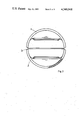
- FIG. 2 is a side elevation of the casing shown in FIG. 1;
- FIG. 3 is a top plan view of the part shown in FIG. 1;
- FIG. 4 is a sectional view taken along the line IV--IV of FIG. 1, with the pipe connections not yet being welded together and being indicated in dash-dotted lines;
- FIGS. 5 through 16 show schematic views of the individual steps of the manufacturing process for different embodiments of the invention.
- FIGS. 1 to 4 show two casing parts 1 and 2 which are to be welded together by a fluid- and pressure-tight longitudinal weld.
- the weld is applied at 3 and it is accessible to both ultrasonic and radiographic inspection, since a sufficiently large approach space is available even for an ultrasonic inspectroscope (not shown), so that there is no risk of invalidating the measuring results.
- Each casing part 1 and 2 is formed with flange-like outer and inner tubular collars 4 and 5 and 6 and 7 which are integral with the casing part and extend to both the outside and to the inside. Collars 4 and 5 and 6 and 7 may be coaxial with each other and, in the embodiment shown, they have identical inside diameters D. In the embodiment of FIG. 1, the longitudinal axes of collars 4 and 5 and 6 and 7 intersect at an obtuse angle because each of the longitudinal axes, for example, forms an angle of about 3% with the horizontal.
- the flange-like collars 5 and 7 which project into the interior are each provided on their free end portions facing the interior with a low-wear lining 8, 9 formed by a welded builtup surface, which cooperates in a sealing manner with a shutoff gate (not shown), for example, a spindle with a hand wheel.
- Valve seat rings may also be welded thereto or these free end portions of collars 5 and 7 may themselves be shaped into a valve seat.
- Collars 4 and 6 are each provided on their sides remote from the interior with a respective bevel 10, 11, to which an indicated pipe connection 12, 13 is to be welded in a fluid- and pressure-tight manner.
- the welds tightly connecting the pipe connections 12, 13 to collars 4, 6 are also fully accessible to both ultrasonic and radiographic inspection.
- a sufficient space at 4a and 6a is available for approaching and ultrasonic inspectoscope, because each of the welds is sufficiently spaced from the casing wall due to the provided collar 4 or 6, so that no distorted results of measurement can be obtained.
- hole 15 is then enlarged or upset by means of suitable forming tools 16, particularly rollers, until the inside diameter D of the pipe connections, or the inside diameter D of collars 4,5 or 6,7, shown in FIGS. 1 and 2, is attained.
- the blank 14, which is thus preshaped, is placed in a forming tool comprising an upper and a lower die 17, 18 (see FIG. 9) which have opposite contours corresponding to the contrours of a finished casing part 1, 2, as shown in FIG. 1.
- a forming tool comprising an upper and a lower die 17, 18 (see FIG. 9) which have opposite contours corresponding to the contrours of a finished casing part 1, 2, as shown in FIG. 1.
- the entire surface area 4a, 6a outside and inside flange-like collars 5,4 or 6,7 is held fast and supported in upper and lower first dies 19 and 20 so that, during the following motion of upper and lower second dies 17 and 18 toward each other into their positions shown in FIG. 10, collars 4,5 or 6,7 cannot warp or otherwise deform.
- Dies 17 and 18 are then moved apart again and the respective casing part 1 or 2 is removed therefrom and is ready to be welded to an identical other casing part to a complete casing, particularly for a gate valve. If necessary, bevels for valves may be produced or finished, in particular, descaled. It is also possible to overform the inner collar 5, 7 during the head-on motion of tools, 19, 20, for example, by pressing it flat prior to applying the respective lining 8, 9 or affixing a valve seat ring.
- FIGS. 11 and 12 show finished casing parts in elevation and section, respectively.
- the manufacture can also start from a flat plate blank 14, such as shown in FIG. 5.
- the hole or port 15 is then rimmed-out to produce a flange-like collar 4, 5 or 6, 7 (FIGS. 1 and 2).
- a rolling or upsetting operation may serve this purpose and may be performed outside the press die proper (FIG. 9), or within the die itself, which is explained hereinafter.
- the casing part 1 or 2 is also possible to manufacture the casing part 1 or 2 from a flat plate or sheet blank 14, according to FIG. 13, and to provide it with a hole.
- the collars 4,5 or 6,7 are then formed on the finished casing part 1 or 2 by upsetting, by means of a forming tool comprising an upper die 21 and lower die 22 and an abutment 23, and a welding bevel for the pipe connection, such as shown at 10, is produced at the same time.
- the collars 4 and 5 or 6 and 7 are produced within forming tools 17 and 18, thus after blank 14 has been formed to a casing part.
- rollers 24 are provided in the example shown.
Landscapes
- Engineering & Computer Science (AREA)
- Mechanical Engineering (AREA)
- General Engineering & Computer Science (AREA)
- Valve Housings (AREA)
Applications Claiming Priority (2)
| Application Number | Priority Date | Filing Date | Title |
|---|---|---|---|
| DE2905744A DE2905744A1 (de) | 1979-02-15 | 1979-02-15 | Verfahren zum herstellen von armaturengehaeusen aus metall, insbesondere aus stahl, vorzugsweise zum herstellen von schiebergehaeusen, und vorrichtung zum durchfuehren des verfahrens |
| DE2905744 | 1979-02-15 |
Publications (1)
| Publication Number | Publication Date |
|---|---|
| US4349948A true US4349948A (en) | 1982-09-21 |
Family
ID=6062969
Family Applications (1)
| Application Number | Title | Priority Date | Filing Date |
|---|---|---|---|
| US06/119,506 Expired - Lifetime US4349948A (en) | 1979-02-15 | 1980-02-07 | Method for manufacturing metal casings for accessories and particularly gate valves |
Country Status (3)
| Country | Link |
|---|---|
| US (1) | US4349948A (fr) |
| EP (1) | EP0014837B1 (fr) |
| DE (2) | DE2905744A1 (fr) |
Cited By (3)
| Publication number | Priority date | Publication date | Assignee | Title |
|---|---|---|---|---|
| US4972577A (en) * | 1988-12-12 | 1990-11-27 | Dierikx Andreas P A | Method for manufacturing gate valves |
| US5522423A (en) * | 1994-08-15 | 1996-06-04 | Elliott; Pat S. | Forged body full port swing check valve |
| CN107107249A (zh) * | 2014-09-25 | 2017-08-29 | 德国派斯塔钢制阀门公司 | 用于制造高压截止阀的壳体中间部件的方法 |
Families Citing this family (2)
| Publication number | Priority date | Publication date | Assignee | Title |
|---|---|---|---|---|
| CN104100094B (zh) * | 2013-04-02 | 2016-07-06 | 中国核工业第五建设有限公司 | 核电站钢制安全壳人员闸门安装方法 |
| CN104759850B (zh) * | 2015-04-03 | 2017-01-04 | 无锡派克新材料科技股份有限公司 | 一种铝合金高筒件加工工艺 |
Citations (11)
| Publication number | Priority date | Publication date | Assignee | Title |
|---|---|---|---|---|
| US157810A (en) * | 1874-12-15 | Improvement in flanging-machines | ||
| US1120100A (en) * | 1914-04-01 | 1914-12-08 | Pressed Metal Radiator Company | Expanding-head. |
| US1679466A (en) * | 1925-11-09 | 1928-08-07 | Joseph Fahys & Company | Method of forming watchcases |
| US1999599A (en) * | 1932-03-18 | 1935-04-30 | White Motor Co | Method of constructing valve seats for internal combustion engines and similar mechanisms |
| DE891952C (de) * | 1953-08-20 | Deutsche Babcock &. Wilcox DamptKessel-Werke A.-G., Oberhausen (RhId.) | Gehäuse für Absperrschieber | |
| DE928861C (de) * | 1950-04-22 | 1955-06-13 | Siepmann Werke Ag | Verfahren zur Herstellung von Schiebergehaeusen aus im Wege des Gesenkschmiedens hergestellten und anschliessend in der Ebene der Spindelachse zusammengeschweissten Halbschalen |
| US2869221A (en) * | 1952-10-21 | 1959-01-20 | Stabl Armaturen G M B H | Method of producing valve housings |
| US3224729A (en) * | 1959-10-26 | 1965-12-21 | Beurel Guy Lucien Marius | Sheet metal sectional gate valves |
| US3511474A (en) * | 1967-12-27 | 1970-05-12 | Gen Signal Corp | Butterfly valve |
| GB1310549A (en) * | 1970-06-23 | 1973-03-21 | Tsniitmash | Method of producing swaged-and-welded bodies of large-size piping valves and fittings and a die set for carrying out the method |
| US4057022A (en) * | 1976-06-01 | 1977-11-08 | Toyota Jidosha Kogyo Kabushiki Kaisha | Vessel having a pattern-molded bottom, a manufacturing process therefor |
Family Cites Families (5)
| Publication number | Priority date | Publication date | Assignee | Title |
|---|---|---|---|---|
| GB569833A (en) * | 1943-10-07 | 1945-06-11 | Bolton S Superheater & Pipewor | Improvements relating to the manufacture of valves for the control of fluids |
| DE1859877U (de) * | 1961-03-07 | 1962-10-11 | Potthoff & Flume G M B H | Absperrschieber fuer transportable leitungen. |
| NL160643C (nl) * | 1969-11-05 | 1979-11-15 | Holland Bergen Machine | Schuifafsluiter. |
| AT307208B (de) * | 1969-11-11 | 1973-05-10 | Tsniitmash | Verfahren und Preßwerkzeug zum Herstellen von aus miteinander verscheweißten Teilen bestehenden Gehäusen für Rohrleitungsgroßarmaturen, Abzweigstücken od.dgl. |
| DE2114065C2 (de) * | 1971-03-23 | 1982-08-19 | Heinrich Pannenbecker | Verfahren zur Herstellung von Folien aus thermoplastischen Kunststoffen mit Klebereigenschaft |
-
1979
- 1979-02-15 DE DE2905744A patent/DE2905744A1/de not_active Ceased
-
1980
- 1980-01-15 DE DE8080100174T patent/DE3060950D1/de not_active Expired
- 1980-01-15 EP EP80100174A patent/EP0014837B1/fr not_active Expired
- 1980-02-07 US US06/119,506 patent/US4349948A/en not_active Expired - Lifetime
Patent Citations (11)
| Publication number | Priority date | Publication date | Assignee | Title |
|---|---|---|---|---|
| US157810A (en) * | 1874-12-15 | Improvement in flanging-machines | ||
| DE891952C (de) * | 1953-08-20 | Deutsche Babcock &. Wilcox DamptKessel-Werke A.-G., Oberhausen (RhId.) | Gehäuse für Absperrschieber | |
| US1120100A (en) * | 1914-04-01 | 1914-12-08 | Pressed Metal Radiator Company | Expanding-head. |
| US1679466A (en) * | 1925-11-09 | 1928-08-07 | Joseph Fahys & Company | Method of forming watchcases |
| US1999599A (en) * | 1932-03-18 | 1935-04-30 | White Motor Co | Method of constructing valve seats for internal combustion engines and similar mechanisms |
| DE928861C (de) * | 1950-04-22 | 1955-06-13 | Siepmann Werke Ag | Verfahren zur Herstellung von Schiebergehaeusen aus im Wege des Gesenkschmiedens hergestellten und anschliessend in der Ebene der Spindelachse zusammengeschweissten Halbschalen |
| US2869221A (en) * | 1952-10-21 | 1959-01-20 | Stabl Armaturen G M B H | Method of producing valve housings |
| US3224729A (en) * | 1959-10-26 | 1965-12-21 | Beurel Guy Lucien Marius | Sheet metal sectional gate valves |
| US3511474A (en) * | 1967-12-27 | 1970-05-12 | Gen Signal Corp | Butterfly valve |
| GB1310549A (en) * | 1970-06-23 | 1973-03-21 | Tsniitmash | Method of producing swaged-and-welded bodies of large-size piping valves and fittings and a die set for carrying out the method |
| US4057022A (en) * | 1976-06-01 | 1977-11-08 | Toyota Jidosha Kogyo Kabushiki Kaisha | Vessel having a pattern-molded bottom, a manufacturing process therefor |
Cited By (6)
| Publication number | Priority date | Publication date | Assignee | Title |
|---|---|---|---|---|
| US4972577A (en) * | 1988-12-12 | 1990-11-27 | Dierikx Andreas P A | Method for manufacturing gate valves |
| US5522423A (en) * | 1994-08-15 | 1996-06-04 | Elliott; Pat S. | Forged body full port swing check valve |
| CN107107249A (zh) * | 2014-09-25 | 2017-08-29 | 德国派斯塔钢制阀门公司 | 用于制造高压截止阀的壳体中间部件的方法 |
| US20170335990A1 (en) * | 2014-09-25 | 2017-11-23 | STAHL-ARMATUREN PERSTA Gesellschaft mit beschraenkter Haftung | Method for producing a housing central part of a high-pressure slide gate valve |
| US10364908B2 (en) * | 2014-09-25 | 2019-07-30 | STAHL-ARMATUREN PERSTA Gesellschaft mit beschraenkter Haftung | Method for producing a housing central part of a high-pressure slide gate valve |
| CN107107249B (zh) * | 2014-09-25 | 2019-10-01 | 德国派斯塔钢制阀门公司 | 用于制造高压截止阀的壳体中间部件的方法 |
Also Published As
| Publication number | Publication date |
|---|---|
| DE2905744A1 (de) | 1980-09-18 |
| EP0014837A1 (fr) | 1980-09-03 |
| EP0014837B1 (fr) | 1982-10-20 |
| DE3060950D1 (en) | 1982-11-25 |
Similar Documents
| Publication | Publication Date | Title |
|---|---|---|
| US1817854A (en) | Process of producing coupling flanges | |
| US2370089A (en) | Tube flanging tool | |
| US4349948A (en) | Method for manufacturing metal casings for accessories and particularly gate valves | |
| US3585709A (en) | Method of making tubular walls from finned pipes | |
| US4416409A (en) | Method for manufacturing a metal casing for gate valves used in nuclear reactors and the like | |
| CN113523733A (zh) | 一种不锈钢水表壳的生产工艺 | |
| JPH07223030A (ja) | 管と板材の接合装置 | |
| JPS6123042B2 (fr) | ||
| JPH07155879A (ja) | 管継手の製造方法及びそれに使用する揺動加工装置 | |
| US4138873A (en) | Tool for forming rectangular cross-sectional conduit ends | |
| US3542991A (en) | Method for manufacturing large tubular shafts | |
| JPS6277143A (ja) | 鍛造方法 | |
| JPS6051926B2 (ja) | 二股管加工装置 | |
| JPS5853329A (ja) | ワンシ−ムt形管継手の製造方法 | |
| JPH02134485A (ja) | 異種金属管継手の製造方法 | |
| US4051709A (en) | Method of producing connector fittings for pipes | |
| JPH09170610A (ja) | ジルコニウム合金管とステンレス鋼管との接合方法 | |
| SU1181743A1 (ru) | Способ выполнени уплотнительных сферических по сков | |
| JPH044940A (ja) | 油圧等の配管用接続金具の成形方法 | |
| JPS5530327A (en) | Pipe making method | |
| RU2087227C1 (ru) | Штамп для изготовления тройников из листовых заготовок | |
| GB2034611A (en) | Valve casings for wedge valves | |
| SU1276400A1 (ru) | Способ изготовлени трубчатых деталей с патрубками | |
| JPH0519140Y2 (fr) | ||
| JPS62107837A (ja) | 管状部材の超音波透過特性の改善方法 |
Legal Events
| Date | Code | Title | Description |
|---|---|---|---|
| STCF | Information on status: patent grant |
Free format text: PATENTED CASE |