US3757747A - Cooling water circulation for multi-cylinder internal combustion engines - Google Patents
Cooling water circulation for multi-cylinder internal combustion engines Download PDFInfo
- Publication number
- US3757747A US3757747A US00195708A US3757747DA US3757747A US 3757747 A US3757747 A US 3757747A US 00195708 A US00195708 A US 00195708A US 3757747D A US3757747D A US 3757747DA US 3757747 A US3757747 A US 3757747A
- Authority
- US
- United States
- Prior art keywords
- cooling water
- cooling
- line
- cylinder
- pass line
- Prior art date
- Legal status (The legal status is an assumption and is not a legal conclusion. Google has not performed a legal analysis and makes no representation as to the accuracy of the status listed.)
- Expired - Lifetime
Links
- 239000000498 cooling water Substances 0.000 title claims abstract description 115
- 238000002485 combustion reaction Methods 0.000 title claims abstract description 16
- 230000004087 circulation Effects 0.000 title description 8
- 238000001816 cooling Methods 0.000 claims description 31
- 238000011144 upstream manufacturing Methods 0.000 claims description 13
- 239000012809 cooling fluid Substances 0.000 claims description 6
- 238000012986 modification Methods 0.000 description 2
- 230000004048 modification Effects 0.000 description 2
- 238000013021 overheating Methods 0.000 description 2
- 241001052209 Cylinder Species 0.000 description 1
Images
Classifications
-
- F—MECHANICAL ENGINEERING; LIGHTING; HEATING; WEAPONS; BLASTING
- F01—MACHINES OR ENGINES IN GENERAL; ENGINE PLANTS IN GENERAL; STEAM ENGINES
- F01P—COOLING OF MACHINES OR ENGINES IN GENERAL; COOLING OF INTERNAL-COMBUSTION ENGINES
- F01P7/00—Controlling of coolant flow
- F01P7/14—Controlling of coolant flow the coolant being liquid
- F01P7/16—Controlling of coolant flow the coolant being liquid by thermostatic control
-
- F—MECHANICAL ENGINEERING; LIGHTING; HEATING; WEAPONS; BLASTING
- F01—MACHINES OR ENGINES IN GENERAL; ENGINE PLANTS IN GENERAL; STEAM ENGINES
- F01P—COOLING OF MACHINES OR ENGINES IN GENERAL; COOLING OF INTERNAL-COMBUSTION ENGINES
- F01P3/00—Liquid cooling
- F01P3/02—Arrangements for cooling cylinders or cylinder heads
Definitions
- ABSTRACT A cooling water circulatory system for multi-cylinder internal combustion engines in which a partial cooling water quantity is branched off from the individual cooling water spaces of the cylinders that are sequentially circumcirculated by the cooling water, and in which the partial cooling water quantities are collected after passage through the respective cylinder heads in a cooling water return line whereby the cooling water space of'a downstream cylinder, as viewed in the flow direction, preferably the last cylinder, is tapped by means of a by-pass line which terminates, by-passing the cylinder heads, in the cooling water line system at a place between the suction side of the cooling water pump and the cylinder heads.
- the present invention relates to a cooling water circulation for multi-cylinder internal combustion engines in which a partial quantity of cooling water is branched off from each of the individual cooling water spaces of the sequentially circumcirculated cylinders and after passage through the associated cylinder head is collected in a cooling water return line.
- the present invention is concerned with the task to improve the cooling water circulatory system of the aforementioned type which is advantageous especially for the use of separate cylinder heads for the individual cylinders, in such a manner that the aforementioned disadvantages are avoided.
- the underlying problems are solved according to the present invention in that the cooling water space of a cylinder disposed downstream in the flow direction is tapped by means of a bypass line and that the by-pass line in by-passing relationship to the cylinder heads terminates in the cooling water line system at a place between the suction side of the cooling water pump and the cylinder heads.
- a still adequate cooling water flow is thus enforced also in the cooling water spaces of the rear or downstream cylinders by means of the by-pass line so that an over-heating and galling of the cylinders are avoided.
- Another object of the present invention resides in a cooling water circulation for multi-cylinder internal combustion engines of the type described above which assures effective and adequate cooling of all the cylin- 'ders.
- a further object of the present invention resides in a cooling water circulatory system for multi-cylinder internal combustion engines which avoids galling due to overheating.
- Another object of the present invention resides in a cooling water circulation for multi-cylinder internal combustion engines in which the cooling water flows sequentially from cylinder to cylinder, and which is so constructed and arranged as to improve the cooling of the cylinders.
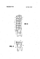
- FIG. 1 is a schematic view of a firstembodiment of a cooling water circulatory system in accordance with the present invention of a six-cylinder in-line engine;
- FIG. 2 is a partial schematic view of a modified embodiment of the cooling water circulatory system generally similar to FIG. 1.
- the engine is generally designated in this figure by reference numeral 10 and the cylinders, indicated only schematically by reference numerals 11 to 16.
- the engine 10 drives a cooling water pump 17 in a conventional manner which forces the cooling water by way of the pressure line 18 successively through the individual cooling water spaces 19 to 24 of the cylinders 11 to 16.
- a partial cooling water quantity for the cooling of the associated cylinder head is branched off from each cooling water space 19 to 24.
- the partial cooling water quantities are returned from the cooling water spaces of the cylinder head by means of branch lines 25 to 30 into a return line 31.
- a radiator 33 and a by-pass line 34 are interconnected in conventional, known parallel arrangement between the return line 31 and the suction line 32 of the cooling water pump 17, which are controlled in a customary manner by a thermostatic control valve 35.
- the cooling water space 24 of the last cylinder 16 is tapped by a by-pass line 36 which, in by-passing relationship of the cooling water spaces ofthe cylinder head, is directly connected at 37 with the suction line 32 of the cooling water pump 17. It is avoided by the use of the by-pass line 36 that a standing cooling water column may form in the rear or downstream cooling water spaces, for example, in the cooling water spaces 22 to 24.
- the by-pass line 36 constitutes a by-pass connection between the cooling water pump 17 and the cooling water spaces 19 to 24 of the cylinders which improves the hot-running behavior of the engine.
- FIG. 2 In the modified embodiment of FIG. 2, in which similar parts are designated by similar reference numerals of the series, the main cooling water circulation is constructed corresponding to that of FIG. 1.
- the sixcylinder in-line engine generally designated by refer ence numeral 100, only the front cylinder 111 and the two first cooling water spaces 119 and 120 of the cylinders are shown in FIG. 2.
- the branch line of the first cylinder head tenninates in the return line indicated by reference numeral 131.
- a radiator 133 and a by-pass line 134 are again interconnected in parallel arrangement between the suction line 132 of the cool ing water pump 117 and the return line 131,.whichare controlled by a thermostatic control valve 135.
- the cooling water space of the last cylinder (not illustrated), is tapped corresponding to the arrangement of FIG. 1 by a by-pass line 136 which is connected to the return line 131 at a place 137 directly upstream of the valve 135.
- the parallel arrangement 133 to 135 is connected between the by-pass line 136 and the suction line 132 whereby a lesser flow quantity establishes itself in the by-pass line 136 withthe same pump output than in the arrangement according .to FIG. 1. Consequently, the line cross sections of the normal cooling water circulation can be taken over possibly unchanged for the cooling water circulatory system according to the present invention.
- a cooling water circulatory system characterized in that the by-pass line means is connected to the cooling water space of the last cylin der as viewed in the direction of flow of the cooling water.
- a cooling water circulatory system characterized in that the return line from the cylinder head includes a parallel arrangement of radiator and by-pass line controlled by a thermostatic control valve means.
- a cooling water circulatory system characterized in that the by-pass line means terminates in the line portion between the suction side of the cooling water pump and the downstream connection of the parallel arrangement consisting of radiator and by-pass line.
- a cooling water circulatory system characterized in that said by-pass line means terminates in the return line upstream of the control valve means.
- a cooling water circulatory system characterized in that said by-pass line means terminates in the return line portion upstream of the control valve means but downstream of the first return line portion from the first cylinder head.
- a cooling fluid circulatory system for multicylinder internal combustion engines comprising a cooling line system including respectively an intake line means, cooling pump means disposed with the intake line means, means for cooling respective cylinders of an internal combustion engine, means for collecting a partial amount of cooling fluid from said means for cooling respective cylinders, and thennostatic control valve means associated with said means for collecting; and by-pass line means extending from said means for cooling respective cylinders associated with a respective cylinder disposed downstream in the flow direction to at least one of a place at the intake means upstream in the flow direction of the cooling pump means and a place at said means for collecting upstream of the thermostatic control valve means.
- a cooling system according to claim 11, wherein said means for cooling respective cylinders includes chamber means associated with respective cylinders, the cooling fluid passing successively between said chamber means in the flow direction.
- a cooling system according to claim 11, wherein said means for collecting includes return line means, said return line means being connected to respective cylinders by branch line means.
- a cooling system according to claim 11, wherein said means for collecting includes a parallel arrangement of radiator means and a second by-pass line means, said parallel arrangement disposed downstream of, and being controlled by, said thermostatic control valve means.
Landscapes
- Engineering & Computer Science (AREA)
- Chemical & Material Sciences (AREA)
- Combustion & Propulsion (AREA)
- Mechanical Engineering (AREA)
- General Engineering & Computer Science (AREA)
- Cylinder Crankcases Of Internal Combustion Engines (AREA)
Applications Claiming Priority (1)
| Application Number | Priority Date | Filing Date | Title |
|---|---|---|---|
| DE2054431A DE2054431C3 (de) | 1970-11-05 | 1970-11-05 | Mehrzylindrige flüssigkeitsgekühlte Brennkraftmaschine mit Zwangsumlaufkühlung |
Publications (1)
| Publication Number | Publication Date |
|---|---|
| US3757747A true US3757747A (en) | 1973-09-11 |
Family
ID=5787215
Family Applications (1)
| Application Number | Title | Priority Date | Filing Date |
|---|---|---|---|
| US00195708A Expired - Lifetime US3757747A (en) | 1970-11-05 | 1971-11-04 | Cooling water circulation for multi-cylinder internal combustion engines |
Country Status (5)
| Country | Link |
|---|---|
| US (1) | US3757747A (show.php) |
| DE (1) | DE2054431C3 (show.php) |
| FR (1) | FR2113606A5 (show.php) |
| GB (1) | GB1329323A (show.php) |
| SE (1) | SE374410B (show.php) |
Cited By (7)
| Publication number | Priority date | Publication date | Assignee | Title |
|---|---|---|---|---|
| US4369738A (en) * | 1980-05-21 | 1983-01-25 | Toyota Jidosha Kogyo Kabushiki Kaisha | Engine cooling system with optionally communicable head cooling circuit and block cooling circuit, and method of operating the same |
| US4370950A (en) * | 1980-12-02 | 1983-02-01 | Toyota Jidosha Kabushiki Kaisha | Engine cooling system and control valve assembly providing mixed or unmixed head and block cooling |
| US4381736A (en) * | 1980-04-18 | 1983-05-03 | Toyota Jidosha Kogyo Kabushiki Kaisha | Engine cooling system providing mixed or unmixed head and block cooling |
| US4553505A (en) * | 1983-07-11 | 1985-11-19 | Nissan Motor Co., Ltd. | Cylinder head of internal combustion engine |
| US5503118A (en) * | 1995-05-23 | 1996-04-02 | Hollis; Thomas J. | Integral water pump/engine block bypass cooling system |
| EP1008733A3 (de) * | 1998-12-12 | 2000-12-06 | DEUTZ Aktiengesellschaft | Ölgekühlter Zylinderkopf |
| US20050056237A1 (en) * | 2003-07-24 | 2005-03-17 | Honda Motor Co., Ltd. | Engine cooling structure |
Families Citing this family (1)
| Publication number | Priority date | Publication date | Assignee | Title |
|---|---|---|---|---|
| DE3602229A1 (de) * | 1986-01-25 | 1987-07-30 | Kloeckner Humboldt Deutz Ag | Fluessigkeitsgekuehlter zylinderkopf in blockbauweise |
Citations (3)
| Publication number | Priority date | Publication date | Assignee | Title |
|---|---|---|---|---|
| US2069749A (en) * | 1934-06-12 | 1937-02-09 | Jacob Z Brubaker | Automatic dual temperature cooling system for motors |
| US2468735A (en) * | 1945-08-18 | 1949-05-03 | Jacob Z Brubaker | Thermostat controlled means for maintaining dual temperature in motors |
| US3646919A (en) * | 1969-07-22 | 1972-03-07 | Daimler Benz Ag | Cooling water conductor system in reciprocating piston internal combustion engines |
-
1970
- 1970-11-05 DE DE2054431A patent/DE2054431C3/de not_active Expired
-
1971
- 1971-11-03 GB GB5112371A patent/GB1329323A/en not_active Expired
- 1971-11-04 SE SE7114110A patent/SE374410B/xx unknown
- 1971-11-04 US US00195708A patent/US3757747A/en not_active Expired - Lifetime
- 1971-11-05 FR FR7139724A patent/FR2113606A5/fr not_active Expired
Patent Citations (3)
| Publication number | Priority date | Publication date | Assignee | Title |
|---|---|---|---|---|
| US2069749A (en) * | 1934-06-12 | 1937-02-09 | Jacob Z Brubaker | Automatic dual temperature cooling system for motors |
| US2468735A (en) * | 1945-08-18 | 1949-05-03 | Jacob Z Brubaker | Thermostat controlled means for maintaining dual temperature in motors |
| US3646919A (en) * | 1969-07-22 | 1972-03-07 | Daimler Benz Ag | Cooling water conductor system in reciprocating piston internal combustion engines |
Cited By (9)
| Publication number | Priority date | Publication date | Assignee | Title |
|---|---|---|---|---|
| US4381736A (en) * | 1980-04-18 | 1983-05-03 | Toyota Jidosha Kogyo Kabushiki Kaisha | Engine cooling system providing mixed or unmixed head and block cooling |
| US4369738A (en) * | 1980-05-21 | 1983-01-25 | Toyota Jidosha Kogyo Kabushiki Kaisha | Engine cooling system with optionally communicable head cooling circuit and block cooling circuit, and method of operating the same |
| US4413596A (en) * | 1980-05-21 | 1983-11-08 | Toyota Jidosha Kabushiki Kaisha | Engine cooling system with optionally communicable head cooling circuit and block cooling circuit, and method of operating the same |
| US4370950A (en) * | 1980-12-02 | 1983-02-01 | Toyota Jidosha Kabushiki Kaisha | Engine cooling system and control valve assembly providing mixed or unmixed head and block cooling |
| US4553505A (en) * | 1983-07-11 | 1985-11-19 | Nissan Motor Co., Ltd. | Cylinder head of internal combustion engine |
| US5503118A (en) * | 1995-05-23 | 1996-04-02 | Hollis; Thomas J. | Integral water pump/engine block bypass cooling system |
| EP1008733A3 (de) * | 1998-12-12 | 2000-12-06 | DEUTZ Aktiengesellschaft | Ölgekühlter Zylinderkopf |
| US20050056237A1 (en) * | 2003-07-24 | 2005-03-17 | Honda Motor Co., Ltd. | Engine cooling structure |
| US7086356B2 (en) * | 2003-07-24 | 2006-08-08 | Honda Motor Co., Ltd. | Engine cooling structure |
Also Published As
| Publication number | Publication date |
|---|---|
| DE2054431B2 (de) | 1973-08-23 |
| FR2113606A5 (show.php) | 1972-06-23 |
| DE2054431A1 (de) | 1972-05-10 |
| SE374410B (show.php) | 1975-03-03 |
| GB1329323A (en) | 1973-09-05 |
| DE2054431C3 (de) | 1974-03-14 |
Similar Documents
| Publication | Publication Date | Title |
|---|---|---|
| US4236492A (en) | Internal combustion engine having a supercharger and means for cooling charged air | |
| US3757747A (en) | Cooling water circulation for multi-cylinder internal combustion engines | |
| GB1167264A (en) | Improvements relating to Cooling Systems for Supercharged Internal Combustion Engines | |
| GB1289201A (show.php) | ||
| GB950020A (en) | Improvements relating to supercharged internal combustion engine cooling arrangements | |
| GB988668A (en) | Radiators for internal combustion engines | |
| GB910100A (en) | Liquid coolant circulation systems for internal combustion engines | |
| GB1331957A (en) | Internal combustion engines | |
| US2716399A (en) | Water heated manifold | |
| US1791572A (en) | Cooling system for internal-combustion engines | |
| GB1279132A (en) | Improvements in or relating to internal combustion engines | |
| JPS5835221A (ja) | 内燃機関の冷却装置 | |
| US3554171A (en) | Cylinder head of an air-cooled internal combustion engine | |
| GB1154777A (en) | Motor Vehicle Heating System | |
| US2953126A (en) | Engine coolant distribution | |
| GB877557A (en) | Improved cooling system for supercharged internal combustion engines | |
| US3570462A (en) | Suction pipe heating by exhaust gas | |
| US2089454A (en) | Internal combustion engine | |
| DE102016106155A1 (de) | Verbrennungsmaschine | |
| GB1015417A (en) | Improvements relating to induction assemblies of internal-combustion engines | |
| US1850246A (en) | Cooling device for internal combustion engines | |
| GB1253940A (en) | Cooling system for an internal combustion engine | |
| GB548270A (en) | Improvements in or relating to supercharged internal-combustion engines | |
| GB482432A (en) | Improvements in or relating to the cooling of the supercharging pumps of internal combustion engines | |
| GB1221421A (en) | Improvements in and relating to cylinder heads for internal combustion engines |