US20170261726A1 - Imaging lens and image capturing device - Google Patents
Imaging lens and image capturing device Download PDFInfo
- Publication number
- US20170261726A1 US20170261726A1 US15/605,670 US201715605670A US2017261726A1 US 20170261726 A1 US20170261726 A1 US 20170261726A1 US 201715605670 A US201715605670 A US 201715605670A US 2017261726 A1 US2017261726 A1 US 2017261726A1
- Authority
- US
- United States
- Prior art keywords
- lens
- refractive power
- conditional expression
- denotes
- imaging
- Prior art date
- Legal status (The legal status is an assumption and is not a legal conclusion. Google has not performed a legal analysis and makes no representation as to the accuracy of the status listed.)
- Abandoned
Links
Images
Classifications
-
- G—PHYSICS
- G02—OPTICS
- G02B—OPTICAL ELEMENTS, SYSTEMS OR APPARATUS
- G02B13/00—Optical objectives specially designed for the purposes specified below
- G02B13/001—Miniaturised objectives for electronic devices, e.g. portable telephones, webcams, PDAs, small digital cameras
- G02B13/0015—Miniaturised objectives for electronic devices, e.g. portable telephones, webcams, PDAs, small digital cameras characterised by the lens design
- G02B13/002—Miniaturised objectives for electronic devices, e.g. portable telephones, webcams, PDAs, small digital cameras characterised by the lens design having at least one aspherical surface
- G02B13/0045—Miniaturised objectives for electronic devices, e.g. portable telephones, webcams, PDAs, small digital cameras characterised by the lens design having at least one aspherical surface having five or more lenses
-
- G—PHYSICS
- G02—OPTICS
- G02B—OPTICAL ELEMENTS, SYSTEMS OR APPARATUS
- G02B13/00—Optical objectives specially designed for the purposes specified below
- G02B13/001—Miniaturised objectives for electronic devices, e.g. portable telephones, webcams, PDAs, small digital cameras
- G02B13/0015—Miniaturised objectives for electronic devices, e.g. portable telephones, webcams, PDAs, small digital cameras characterised by the lens design
- G02B13/002—Miniaturised objectives for electronic devices, e.g. portable telephones, webcams, PDAs, small digital cameras characterised by the lens design having at least one aspherical surface
-
- G—PHYSICS
- G02—OPTICS
- G02B—OPTICAL ELEMENTS, SYSTEMS OR APPARATUS
- G02B9/00—Optical objectives characterised both by the number of the components and their arrangements according to their sign, i.e. + or -
- G02B9/60—Optical objectives characterised both by the number of the components and their arrangements according to their sign, i.e. + or - having five components only
Definitions
- the present invention relates to an imaging lens suitably used for an image capturing device embedded in a mobile terminal or the like.
- Imaging lenses used in small image capturing devices embedded in mobile terminals or the like are required to have high resolving power of about 1 to 2 ⁇ m on an imaging surface, due to development of image sensors with increased pixels.
- the imaging lenses are also required to have a shorter entire length due to reduced thickness of mobile terminals or the like.
- the high resolving power may be achieved by an imaging lens having an aspherical lens surface.
- An imaging lens having an aspherical lens surface is an aspherical lens surface.
- Another possible solution is to increase the number of lens to achieve the imaging lens with high resolving power. Logically, the increased number of lenses simply leads to a larger space required for the lenses to be inserted, and thus results in a longer length of the entire imaging lens.
- Patent Document 1 WO2013/027641(A1)
- the conventional imaging lenses have had room for improvement to achieve an imaging lens having short entire length and a high imaging performance.
- the present invention is made in view of the above, and an object of the present invention is to provide an imaging lens having a short entire length and a favorable imaging performance and to provide an image capturing device using the same.
- an imaging lens has an image surface curved to have a concave surface facing an object, the imaging lens comprising five lenses including a positive lens and a negative lens. At least one negative lens in the five lenses is disposed to an image side of a positive lens.
- fc denotes a combined focal length of the positive lens and the negative lens with the largest positive refractive power as the combined refractive power
- f denotes a focal length of the imaging lens.
- An imaging lens has an image surface curved to have a concave surface facing an object, the imaging lens comprising in order from the object: a first lens having lens surfaces on both sides curved to have convex surfaces facing the object; a second lens having positive refractive power; a third lens having negative refractive power; a fourth lens having positive refractive power or negative refractive power; and a fifth lens having positive refractive power or negative refractive power.
- f 23 denotes a combined focal length of the second lens and the third lens
- f denotes a focal length of the imaging lens.
- An image capturing device comprises: an imaging lens with which an image of an object is formed on an imaging surface; and an image sensor configured to obtain the image of the object formed on the imaging surface.
- the imaging lens comprises five lenses including a positive lens and a negative lens. At least one negative lens in the five lenses is disposed to an image side of a positive lens.
- fc denotes a combined focal length of the positive lens and the negative lens with the largest positive refractive power as the combined refractive power
- f denotes a focal length of the imaging lens.
- an imaging lens having a favorable imaging performance and a short entire length can be achieved.
- FIG. 1 is a diagram illustrating a lens configuration of an imaging lens according to Example 1.
- FIG. 2 is graphs illustrating various aberrations of the imaging lens according to Example 1.
- FIG. 3 is a diagram illustrating a lens configuration of an imaging lens according to Example 2.
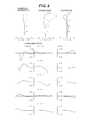
- FIG. 4 is graphs illustrating various aberrations of the imaging lens according to Example 2.
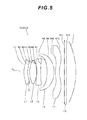
- FIG. 5 is a diagram illustrating a lens configuration of an imaging lens according to Example 3.
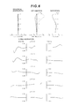
- FIG. 6 is graphs illustrating various aberrations of the imaging lens according to Example 3.
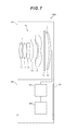
- FIG. 7 is a cross-sectional view of an image capturing device.
- FIG. 7 illustrates an image capturing device CMR including an imaging lens according to the present application.
- FIG. 7 is a cross-sectional view of the image capturing device CMR embedded in a mobile terminal or the like.
- the image capturing device CMR mainly includes: a barrel BR provided in a device main body BD of the mobile terminal or the like; an imaging lens PL contained and held in the barrel BR; an image sensor SR contained in the barrel BR; and a control unit PU contained in the device main body BD.
- the imaging lens PL an image of a subject (object) is formed on an imaging surface of the image sensor SR.
- the image sensor SR includes an image sensor such as a CCD or a CMOS, and is disposed along an image surface I of the imaging lens PL.
- the image sensor SR has a surface as an imaging surface on which pixels (photoelectric conversion elements) are two-dimensionally formed.
- the imaging surface of the image sensor SR is curved to have a concave surface facing the object.
- the imaging lens PL has the image surface I curved along the imaging surface of the image sensor SR.
- the image sensor SR has the imaging surface as a spherical concave surface or an aspherical concave surface.
- the image sensor SR photoelectrically converts light from the subject, focused on the imaging surface with the imaging lens PL, and outputs the resultant image data on the subject to the control unit PU or the like.
- the control unit PU is electrically connected to: the image sensor SR; an I/O unit DS provided on an outer side of the device main body BD of the mobile terminal or the like; and a storage unit MR contained in the device main body BD.
- the I/O unit DS including a touch panel and a liquid crystal panel, executes processing corresponding to an operation (such as an image capturing operation) of a user, displays the subject image obtained by the image sensor SR, or the other like processing.
- the storage unit MR stores data required for operations of the image sensor SR or the like, and the image data on the subject obtained by the image sensor SR.
- the control unit PU controls each of the image sensor SR, the I/O unit DS, the storage unit MR, or the like.
- the control unit PU can execute various types of image processing on the image data on the subject obtained by the image sensor SR.
- the imaging lens PL according to the first embodiment includes five lenses L 1 to L 5 including both a positive lens and a negative lenss, and has the image surface I curved to have the concave surface facing the object.
- the image surface I of the imaging lens PL is curved more largely toward the object, as it gets closer to a peripheral portion from an optical axis Ax.
- At least one negative lens, in the five lenses L 1 to L 5 is disposed to an image side of the positive lens.
- One of a set of the positive lens and the negative lens disposed to the image side of the positive lens that has the largest positive refractive power as combined refractive power (for example, a set of a second lens L 2 having the positive refractive power and a third lens L 3 having negative refractive power) satisfies a condition indicated by the following conditional expression (1).
- fc denotes a combined focal length of the positive lens and the negative lens with the largest positive refractive power as the combined refractive power
- f denotes a focal length of the imaging lens PL.
- the image surface I of the imaging lens PL is curved to have the concave surface facing the object, and thus a load for correcting the curvature of field can be reduced.
- a favorable imaging performance can be achieved with a smaller number of lenses and thus with a shorter length of the entire imaging lens PL.
- the conditional expression (1) is for determining an appropriate range of a relationship between the combined focal length fc of the positive lens and the negative lens with the largest positive refractive power as the combined refractive power and the focal length f of the entire imaging lens PL.
- a condition with a value that is smaller than the lower limit value of the conditional expression (1) is unfavorable because it results in the combined focal length fc that is excessively short rendering the correction of the curvature of field difficult.
- Increasing the number of lenses to correct the curvature of field leads to a longer length of the entire imaging lens, resulting in an insufficient back focus.
- a condition with a value that is larger than the upper limit value of the conditional expression (1) is unfavorable because it results in the combined focal length fc that is excessively long resulting in a long length of the entire imaging lens.
- the lower limit value of the conditional expression (1) is preferably set to be 0.80.
- the upper limit value of the conditional expression (1) is preferably set to be 1.10.
- the imaging lens PL having the configuration described above preferably satisfies a condition indicated by the following conditional expression (2).
- SAG denotes an amount of curvature of the image surface I in an optical axis direction at a maximum image height.
- the conditional expression (2) is for determining an appropriate range of a relationship between the amount of curvature SAG of the image surface I in the optical axis direction at the maximum image height and the combined focal length fc of the positive lens and the negative lens with the largest positive refractive power as the combined refractive power.
- a condition with a value that is smaller than the lower limit value of the conditional expression (2) is unfavorable because it results in the combined focal length fc that is excessively short rendering the correction of various aberrations such as a coma aberration difficult.
- the lower limit value of the conditional expression (2) is preferably set to be ⁇ 0.20.
- the upper limit value of the conditional expression (2) is preferably set to be ⁇ 0.12.
- the imaging lens PL having the configuration described above preferably includes the five lenses L 1 to L 5 including at least one negative lens formed of an optical material with an Abbe number of 40 or smaller, and satisfies a condition indicated by the following conditional expression (3).
- ra denotes a radius of curvature of an object-side lens surface of the negative lens formed of the optical material with an Abbe number of 40 or smaller
- rb denotes a radius of curvature of an image-side lens surface of the negative lens formed of the optical material with an Abbe number of 40 or smaller.
- At least one negative lens formed of the optical material with a small Abbe number is required for correcting a chromatic aberration.
- the negative lens needs to have a certain level of refractive power to favorably correct the chromatic aberration.
- the conditional expression (3) is for determining an appropriate range for a shape factor of the negative lens formed of the optical material with an Abbe number of 40 or smaller. A condition with a value that is larger than the upper limit value of the conditional expression (3) results in the negative lens formed of the optical material with an Abbe number of 40 or smaller having the image-side lens surface with a radius of curvature smaller than that of the object-side lens surface.
- an upper side light flux of a grazing incidence light flux passes through a position of the image-side lens surface of the negative lens farther from the optical axis Ax than that of the object-side lens surface, and thus is largely refracted on the image-side lens surface. This renders the correction of a coma aberration difficult and results in light falloff at edges, and thus is unfavorable.
- the upper limit value of the conditional expression (3) is preferably set to be ⁇ 0.30.
- the negative lens formed of the optical material with an Abbe number of 40 or smaller is preferably a negative lens (for example, the third lens L 3 having the negative refractive power) in the set of lenses with the largest positive refractive power as the combined refractive power.
- a lens (first lens L 1 ), in the five lenses L 1 to L 5 , closest to the object has lens surfaces on both sides curved to have convex surfaces facing the object, and satisfies a condition indicated by the following conditional expression (4).
- fa denotes a focal length of the lens closest to the object.
- the object-side lens surface preferably does not protrude toward the object beyond the center of the lens surface, in terms of keeping the length of the lens short.
- the lens closest to the object in the five lenses L 1 to L 5 needs to have a portion convex toward the object side.
- the conditional expression (4) is for determining an appropriate range of a relationship between the focal length f of the entire imaging lens PL and the focal length fa of the lens closest to the object.
- a condition with a value that is larger than the upper limit value of the conditional expression (4) is unfavorable because it leads to a lens more on the image side than an aperture stop S having excessively high negative refractive power when the lens closest to the object has the positive refractive power, rendering the correction of the coma aberration difficult and resulting in light falloff at edges.
- the lens closest to the object having the negative refractive power is unfavorable because it leads to the back focus that is longer than necessary, resulting in a long length of the entire imaging lens.
- the upper limit value of the conditional expression (4) is preferably set to be 0.25.
- the imaging lens PL having the configuration described above preferably satisfies a condition indicated by the following conditional expression (5).
- fp denotes a focal length of a positive lens in the set of lenses with the largest positive refractive power as the combined refractive power.
- the conditional expression (5) is for determining an appropriate range of a relationship between the focal length fp of the positive lens of the set of lenses with the largest positive refractive power as the combined refractive power and the focal length f of the entire imaging lens PL.
- a condition with a value that is smaller than the lower limit value of the conditional expression (5) is unfavorable because it leads to the focal length fp of the positive lens that is excessively short, rendering the correction of various aberrations, such as a spherical aberration and the coma aberration, difficult.
- a condition with a value that is larger than the upper limit value of the conditional expression (5) is unfavorable because it leads to the focal length fp of the positive lens that is excessively long, resulting in a long length of the entire imaging lens.
- the lower limit value of the conditional expression (5) is preferably set to be 0.55.
- the upper limit value of the conditional expression (5) is preferably set to be 0.65.
- a lens (first lens L 1 ), in the five lenses L 1 to L 5 , closest to the object has lens surfaces on both sides curved to have convex surfaces facing the object, and a condition indicated by the following conditional expressions (6) and (7) is satisfied.
- Y denotes a maximum image height of the imaging lens PL
- Fno denotes an F number of the imaging lens PL
- fa denotes a focal length of the lens closest to the object.
- the conditional expression (6) is for determining an appropriate range of a relationship among the maximum image height Y of the imaging lens PL, the F number Fno of the imaging lens PL, and the focal length fa of the lens closest to the object.
- a condition with a value that is smaller than the lower limit value of the conditional expression (6) is unfavorable because it leads to the lens closest to the object having excessively high negative refractive power leading to the back focus that is longer than necessary, resulting in a long length of the entire imaging lens.
- a condition with a value that is larger than the upper limit value of the conditional expression (6) is unfavorable because it leads to a lens more on the image side than the aperture stop S having excessively high negative refractive power when the positive refractive power of the lens closest to the object is large, rendering the correction of the coma aberration difficult and resulting in light falloff at edges.
- the lower limit value of the conditional expression (6) is preferably set to be ⁇ 0.05.
- the upper limit value of the conditional expression (6) is preferably set to be 0.05.
- the conditional expression (7) is for determining an appropriate range of a relationship between the focal length fa of the lens closest to the object and the combined focal length fc of the positive lens and the negative lens with the largest positive refractive power as the combined refractive power.
- a condition with a value that is smaller than the lower limit value of the conditional expression (7) is unfavorable because the combined focal length fc needs to be short when the negative refractive power of the lens closest to the object is excessively large, rendering the correction of the spherical aberration difficult.
- the condition is unfavorable because an incident angle of a lower side light flux incident on the positive lens in the set of lenses with the largest positive refractive power as the combined refractive power is large when the positive refractive power of the lens closest to the object is excessively large, rendering the correction of the coma aberration difficult.
- the lower limit value of the conditional expression (7) is preferably set to be 10.0.
- a lens (first lens L 1 ), in the five lenses L 1 to L 5 , closest to the object has lens surfaces on both sides curved to have convex surfaces facing the object.
- a bonded-multilayer diffractive optical element (DOE) may be provided on a lens surface of at least any one of the lens closest to the object, and the positive lens and the negative lens with the largest positive refractive power as the combined refractive power.
- the imaging lens PL according to the second embodiment has a configuration similar to that of the imaging lens PL according to the first embodiment, and thus is described with reference numerals that are the same as those in the first embodiment. For example, as illustrated in FIG.
- the imaging lens PL includes: a first lens L 1 having lens surfaces on both sides curved to have convex surfaces facing the object; a second lens L 2 having positive refractive power; a third lens L 3 having negative refractive power; a fourth lens L 4 having positive refractive power (or negative refractive power) ; and a fifth lens L 5 having negative refractive power (or positive refractive power) which are disposed in order from the object along the optical axis Ax.
- An image surface I is curved to have a concave surface facing the object. More specifically, the image surface I of the imaging lens PL is curved more toward the object, as it gets closer to the peripheral portion from the optical axis Ax.
- the imaging lens PL having such a configuration satisfies a condition indicated by the following conditional expression (11).
- f 23 denotes a combined focal length of the second lens L 2 and the third lens L 3 .
- f denotes a focal length of the imaging lens PL.
- the image surface I of the imaging lens PL is curved to have the concave surface facing the object, and thus a load for correcting the curvature of field can be reduced.
- the conditional expression (11) is for determining an appropriate range of a relationship between the combined focal length f 23 of the second lens L 2 and third lens L 3 and the focal length f of the entire imaging lens PL.
- a condition with a value that is smaller than the lower limit value of the conditional expression (11) is unfavorable because it results in the combined focal length f 23 that is excessively short rendering the correction of the curvature of field difficult.
- a condition with a value that is larger than the upper limit value of the conditional expression (11) is unfavorable because it results in the combined focal length f 23 that is excessively long resulting in a long length of the entire imaging lens.
- the lower limit value of the conditional expression (11) is preferably set to be 0.80.
- the upper limit value of the conditional expression (11) is preferably set to be 1.10.
- the imaging lens PL having the configuration described above preferably satisfies a condition indicated by the following conditional expression (12).
- SAG denotes an amount of curvature of the image surface I in an optical axis direction at a maximum image height.
- the conditional expression (12) is for determining an appropriate range of a relationship between the amount of curvature SAG of the image surface I in the optical axis direction at the maximum image height and the combined focal length f 23 of the second lens L 2 and the third lens L 3 .
- a condition with a value that is smaller than the lower limit value of the conditional expression (12) is unfavorable because it results in the combined focal length f 23 that is excessively short rendering the correction of various aberrations such as the coma aberration difficult.
- the amount of curvature SAG of the image surface I in the optical axis direction is too large in a negative direction, a long back focus is required to prevent interference between the last lens and the image sensor, resulting in a long length of the entire imaging lens.
- a condition with a value that is larger than the upper limit value of the conditional expression (12) is unfavorable because it results in a large load on a lens for correcting the curvature of field when the amount of curvature SAG of the image surface I in the optical axis direction is too small, rendering the correction of the curvature of field difficult.
- Increasing the number of lenses to correct the curvature of field leads to a longer length of the entire imaging lens.
- the combined focal length f 23 that is excessively long is unfavorable because it results in a long length of the entire imaging lens.
- the lower limit value of the conditional expression (12) is preferably set to be ⁇ 0.20.
- the upper limit value of the conditional expression (12) is preferably set to be ⁇ 0.12.
- the imaging lens PL having the configuration described above preferably satisfies a condition indicated by the following conditional expression (13).
- r 31 denotes a radius of curvature of an object-side lens surface of the third lens L 3 .
- r 32 denotes a radius of curvature of an image-side lens surface of the third lens L 3 .
- At least one negative lens formed of an optical material with a small Abbe number is required for correcting a chromatic aberration.
- the negative lens needs to have a certain level of refractive power to successfully correct the chromatic aberration.
- the conditional expression (13) is for determining an appropriate range for a shape factor of the third lens L 3 with the negative refractive power. A condition with a value that is larger than the upper limit value of the conditional expression (13) results in the third lens L 3 having the image-side lens surface with a radius of curvature smaller than that of the object-side lens surface.
- an upper side light flux of a grazing incidence light flux passes through a position of the image-side lens surface of the third lens L 3 farther from the optical axis Ax than that of the object-side lens surface, and thus is largely refracted on the image-side lens surface. This renders the correction of the coma aberration difficult and results in light falloff at edges, and thus is unfavorable.
- the upper limit value of the conditional expression (13) is preferably set to be ⁇ 0.30.
- the imaging lens PL having the configuration described above preferably satisfies a condition indicated by the following conditional expression (14).
- fl denotes a focal length of the first lens L 1 .
- the object-side lens surface preferably does not protrude toward the object beyond the center of the lens surface, so that the length of the lens can be kept short.
- the first lens L 1 closest to the object in the five lenses L 1 to L 5 needs to have a portion convex toward the object.
- the conditional expression (14) is for determining an appropriate range of a relationship between the focal length f of the entire imaging lens PL and the focal length fl of the first lens L 1 .
- a condition with a value that is larger than the upper limit value of the conditional expression (14) is unfavorable because it leads to a lens more on the image side than the aperture stop S having excessively high negative refractive power when the first lens L 1 has the positive refractive power, rendering the correction of the coma aberration difficult and resulting in light falloff at edges.
- the first lens L 1 having the negative refractive power is unfavorable because it leads to the back focus that is longer than necessary, resulting in a long length of the entire imaging lens.
- the upper limit value of the conditional expression (14) is preferably set to be 0.25.
- the imaging lens PL having the configuration described above preferably satisfies a condition indicated by the following conditional expression (15).
- f 2 denotes a focal length of the second lens L 2 .
- the conditional expression (15) is for determining an appropriate range of a relationship between the focal length f 2 of the second lens L 2 and the focal length f of the entire imaging lens PL.
- a condition with a value that is smaller than the lower limit value of the conditional expression (15) is unfavorable because it leads to the focal length f 2 of the second lens L 2 that is excessively short, rendering the correction of various aberrations, such as the spherical aberration and the coma aberration, difficult.
- a condition with a value that is larger than the upper limit value of the conditional expression (15) is unfavorable because it leads to the focal length f 2 of the second lens L 2 that is excessively long, resulting in a long length of the entire imaging lens.
- the lower limit value of the conditional expression (15) is preferably set to be 0.55.
- the upper limit value of the conditional expression (15) is preferably set to be 0.65.
- the imaging lens PL having the configuration described above preferably satisfies a condition indicated by the following conditional expressions (16) and (17).
- Y denotes a maximum image height of the imaging lens PL
- Fno denotes is an F number of the imaging lens PL
- f 1 denotes a focal length of the first lens L 1 .
- the conditional expression (16) is for determining an appropriate range of a relationship among the maximum image height Y of the imaging lens PL, the F number Fno of the imaging lens PL, and the focal length f 1 of the first lens L 1 .
- a condition with a value that is smaller than the lower limit value of the conditional expression (16) is unfavorable because it leads to the first lens L 1 having excessively high negative refractive power leading to the back focus that is longer than necessary, resulting in a long length of the entire imaging lens.
- a condition with a value that is larger than the upper limit value of the conditional expression (16) is unfavorable because it leads to a lens more on the image side than the aperture stop S having excessively high negative refractive power when the positive refractive power of the first lens L 1 is large, rendering the correction of the coma aberration difficult and resulting in light falloff at edges.
- the lower limit value of the conditional expression (16) is preferably set to be ⁇ 0.05.
- the upper limit value of the conditional expression (16) is preferably set to be 0.05.
- the conditional expression (17) is for determining an appropriate range of a relationship between the focal length f 1 of the first lens L 1 and the combined focal length f 23 of the second lens L 2 and the third lens L 3 .
- a condition with a value that is smaller than the lower limit value of the conditional expression (17) is unfavorable because it results in the combined focal length f 23 that needs to be short when the negative refractive power of the first lens L 1 is excessively large, rendering the correction of the spherical aberration difficult.
- the condition is unfavorable because an incident angle of a lower side light flux incident on the second lens L 2 is large when the positive refractive power of the first lens L 1 is excessively large, rendering the correction of the coma aberration difficult.
- the lower limit value of the conditional expression (17) is preferably set to be 10.0.
- a bonded-multilayer diffractive optical element may be provided on a lens surface of at least any one of the first lens L 1 , the second lens L 2 , and the third lens L 3 .
- DOE diffractive optical element
- the image surface I has a curved shape to have a concave surface facing the object as illustrated in the figures referred to in Examples described below.
- the curved shape is a spherical shape in terms of manufacturing, but is not limited to the spherical shape, and an aspherical concave surface may be employed.
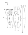
- FIG. 1 is a diagram illustrating a lens configuration of an imaging lens PL (PL 1 ) according to Example 1.
- the imaging lens PL 1 according to Example 1 includes: a first lens L 1 having negative refractive power; a second lens L 2 having positive refractive power; a third lens L 3 having negative refractive power; a fourth lens L 4 having positive refractive power; and a fifth lens L 5 having negative refractive power which are disposed in order from the object along the optical axis Ax.
- the image surface I of the imaging lens PL 1 is curved into a spherical shape to have a concave surface facing the object.
- a parallel flat plate CV including a cover glass of the image sensor or the like, is disposed between the fifth lens L 5 and the image surface I.
- Both side lens surfaces of the first lens L 1 are curved to have aspherical convex surfaces facing the object.
- An aperture stop S is provided, by insert molding, close to the image-side lens surface of the first lens L 1 .
- Both side lens surfaces of the second lens L 2 are aspherical surfaces.
- Both side lens surfaces of the third lens L 3 are aspherical surfaces.
- Both side lens surfaces of the fourth lens L 4 are aspherical surfaces.
- Both side lens surfaces of the fifth lens L 5 are aspherical surfaces.
- Table 1 to Table 3 described below are tables illustrating specification values of imaging lenses according to Example 1 to Example 3.
- [Overall specifications] includes values of the imaging lens PL such as: a focal length f; an F number Fno; half angle of view ⁇ ; and a maximum image height Y.
- a mark * on the right of the first column (surface number) indicates that the lens surface is an aspherical surface.
- a corresponding value of each conditional expression is written in [Conditional expression corresponding value].
- Example 1 specification values in Example 1 are listed.
- the radii of curvature R of 1st to 13th surfaces in Table 1 respectively correspond to reference numerals R 1 to R 13 denoting 1st to 13th surfaces in FIG. 1 .
- 1st surface, 2nd surface, and 4th to 11th surfaces are aspherical lens surfaces.
- the first lens L 1 is one of the five lenses L 1 to L 5 that is closest to the object.
- the second lens L 2 and the third lens L 3 form one of sets, each including a positive lens and a negative lens disposed to the image side of the positive lens, having the largest positive refractive power as the combined refractive power.
- the third lens L 3 is a negative lens formed of an optical material with an Abbe number of 40 or smaller.
- conditional expression (1) is the same as the conditional expression (11)
- conditional expression (2) is the same as the conditional expression (12)
- conditional expression (3) is the same as the conditional expression (13)
- conditional expression (4) is the same as the conditional expression (14)
- conditional expression (5) is the same as the conditional expression (15)
- conditional expression (6) is the same as the conditional expression (16)
- conditional expression (7) is the same as the conditional expression (17).
- f 45 denotes the combined focal length of the fourth lens L 4 and the fifth lens L 5 .
- the fourth lens L 4 and the fifth lens L 5 form one of sets, each including a positive lens and a negative lens disposed to the image side of the positive lens, not having the largest positive refractive power as the combined refractive power.
- the corresponding value of the reference formula (B) is not included within the range of the conditional expression (1).
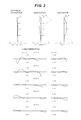
- FIG. 2 is graphs illustrating various aberrations of the imaging lens PL 1 according to Example 1.
- a solid line represents a sagittal image surface
- a broken line represents a meridional image surface.
- RFH denotes Relative Field Height. The description on the aberration graphs similarly applies to the other Examples.
- Example 1 It can be seen in the aberration graphs that in Example 1, various aberrations are successfully corrected and an excellent imaging performance is achieved. All things considered, the excellent imaging performance of the image capturing device CMR including the imaging lens PL 1 according to Example 1 can be guaranteed.
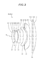
- FIG. 3 is a diagram illustrating a lens configuration of an imaging lens PL (PL 2 ) according to Example 2.
- the imaging lens PL 2 according to Example 2 includes: a first lens L 1 having positive refractive power; a second lens L 2 having positive refractive power; a third lens L 3 having negative refractive power; a fourth lens L 4 having positive refractive power; and a fifth lens L 5 having negative refractive power which are disposed in order from the object along the optical axis Ax.
- the image surface I of the imaging lens PL 2 is curved into a spherical shape to have a concave surface facing the object.
- a parallel flat plate CV including a cover glass of the image sensor or the like, is disposed between the fifth lens L 5 and the image surface I.
- Both side lens surfaces of the first lens L 1 are curved to have aspherical convex surfaces facing the object.
- An aperture stop S is provided, by insert molding, close to the image-side lens surface of the first lens L 1 .
- Both side lens surfaces of the second lens L 2 are aspherical surfaces.
- Both side lens surfaces of the third lens L 3 are aspherical surfaces.
- Both side lens surfaces of the fourth lens L 4 are aspherical surfaces.
- Both side lens surfaces of the fifth lens L 5 are aspherical surfaces.
- Example 2 specification values in Example 2 are listed.
- the radii of curvature R of 1st to 13th surfaces in Table 2 respectively correspond to reference numerals R 1 to R 13 denoting 1st to 13th surfaces in FIG. 3 .
- 1st surface, 2nd surface, and 4th to 11th surfaces are aspherical lens surfaces.
- the first lens L 1 is one of the five lenses L 1 to L 5 that is closest to the object.
- the second lens L 2 and the third lens L 3 form one of sets, each including a positive lens and a negative lens disposed to the image side of the positive lens, having the largest positive refractive power as the combined refractive power.
- the third lens L 3 is a negative lens formed of an optical material with an Abbe number of 40 or smaller.
- conditional expression (1) is the same as the conditional expression (11)
- conditional expression (2) is the same as the conditional expression (12)
- conditional expression (3) is the same as the conditional expression (13)
- conditional expression (4) is the same as the conditional expression (14)
- conditional expression (5) is the same as the conditional expression (15)
- conditional expression (6) is the same as the conditional expression (16)
- conditional expression (7) is the same as the conditional expression (17).
- the fourth lens L 4 and the fifth lens L 5 form one of sets, each including a positive lens and a negative lens disposed to the image side of the positive lens, not having the largest positive refractive power as the combined refractive power.
- the corresponding value of the reference formula (B) is not included within the range of the conditional expression (1).
- FIG. 4 is graphs illustrating various aberrations of the imaging lens PL 2 according to Example 2. It can be seen in the aberration graphs that in Example 2, various aberrations are successfully corrected and an excellent imaging performance is achieved. All things considered, the excellent imaging performance of the image capturing device CMR including the imaging lens PL 2 according to Example 2 can be guaranteed.
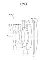
- FIG. 5 is a diagram illustrating a lens configuration of an imaging lens PL (PL 3 ) according to Example 3.
- the imaging lens PL 3 according to Example 3 includes: a first lens L 1 having positive refractive power; a second lens L 2 having positive refractive power; a third lens L 3 having negative refractive power; a fourth lens L 4 having positive refractive power; and a fifth lens L 5 having negative refractive power which are disposed in order from the object along the optical axis Ax.
- the image surface I of the imaging lens PL 3 is curved into a spherical shape to have a concave surface facing the object.
- a parallel flat plate CV including a cover glass of the image sensor or the like, is disposed between the fifth lens L 5 and the image surface I.
- Both side lens surfaces of the first lens L 1 are curved to have aspherical convex surfaces facing the object.
- An aperture stop S is provided, by insert molding, close to the image-side lens surface of the first lens L 1 .
- Both side lens surfaces of the second lens L 2 are aspherical surfaces.
- Both side lens surfaces of the third lens L 3 are aspherical surfaces.
- Both side lens surfaces of the fourth lens L 4 are aspherical surfaces.
- Both side lens surfaces of the fifth lens L 5 are aspherical surfaces.
- Example 3 specification values in Example 3 are listed.
- the radii of curvature R of 1st to 13th surfaces in Table 3 respectively correspond to reference numerals R 1 to R 13 denoting 1st to 13th surfaces in FIG. 5 .
- 1st surface, 2nd surface, and 4th to 11th surfaces are aspherical lens surfaces.
- the first lens L 1 is one of the five lenses L 1 to L 5 that is closest to the object.
- the second lens L 2 and the third lens L 3 form one of sets, each including a positive lens and a negative lens disposed to the image side of the positive lens, having the largest positive refractive power as the combined refractive power.
- the third lens L 3 is a negative lens formed of an optical material with an Abbe number of 40 or smaller.
- conditional expression (1) is the same as the conditional expression (11)
- conditional expression (2) is the same as the conditional expression (12)
- conditional expression (3) is the same as the conditional expression (13)
- conditional expression (4) is the same as the conditional expression (14)
- conditional expression (5) is the same as the conditional expression (15)
- conditional expression (6) is the same as the conditional expression (16)
- conditional expression (7) is the same as the conditional expression (17).
- the fourth lens L 4 and the fifth lens L 5 form one of sets, each including a positive lens and a negative lens disposed to the image side of the positive lens, not having the largest positive refractive power as the combined refractive power.
- the corresponding value of the reference formula (B) is not included within the range of the conditional expression (1).
- FIG. 6 is graphs illustrating various aberrations of the imaging lens PL 3 according to Example 3. It can be seen in the aberration graphs that in Example 3, various aberrations are successfully corrected and an excellent imaging performance is achieved. All things considered, the excellent imaging performance of the image capturing device CMR including the imaging lens PL 3 according to Example 3 can be guaranteed.
- an imaging lens having a short entire length and a favorable imaging performance, and an image capturing device including the same can be implemented.
- the image surface I of the imaging lens PL is curved to have a spherical concave surface facing the object.
- another curved shape such as an aspherical curved shape may be employed.
- the fourth lens L 4 has positive refractive power. However, this should not be construed in a limiting sense, and the fourth lens L 4 may have negative refractive power.
- the fifth lens L 5 has negative refractive power. However, this should not be construed in a limiting sense, and the fifth lens L 5 may have positive refractive power.
- the second lens L 2 and the third lens L 3 form one of the sets, each including a positive lens and a negative lens disposed to an image side of the positive lens, with the largest positive refractive power as the combined refractive power.
- the fourth lens L 4 and the fifth lens L 5 may form the set of positive and negative lenses with the largest positive refractive power as the combined refractive power.
- a bonded-multilayer diffractive optical element may be provided on a lens surface of at least one of the first lens L 1 , the second lens L 2 , and the third lens L 3 .
- the aperture stop S disposed close to the first lens L 1 , is preferably disposed close to an image-side lens surface of the first lens L 1 for the sake of aberration correction.
- the aperture stop may not be provided as a component, and its function may be achieved with a frame of a lens.
Applications Claiming Priority (1)
| Application Number | Priority Date | Filing Date | Title |
|---|---|---|---|
| PCT/JP2014/005968 WO2016084117A1 (ja) | 2014-11-28 | 2014-11-28 | 撮像レンズおよび撮像装置 |
Related Parent Applications (1)
| Application Number | Title | Priority Date | Filing Date |
|---|---|---|---|
| PCT/JP2014/005968 Continuation WO2016084117A1 (ja) | 2014-11-28 | 2014-11-28 | 撮像レンズおよび撮像装置 |
Publications (1)
| Publication Number | Publication Date |
|---|---|
| US20170261726A1 true US20170261726A1 (en) | 2017-09-14 |
Family
ID=56073742
Family Applications (1)
| Application Number | Title | Priority Date | Filing Date |
|---|---|---|---|
| US15/605,670 Abandoned US20170261726A1 (en) | 2014-11-28 | 2017-05-25 | Imaging lens and image capturing device |
Country Status (3)
| Country | Link |
|---|---|
| US (1) | US20170261726A1 (ja) |
| JP (1) | JP6455522B2 (ja) |
| WO (1) | WO2016084117A1 (ja) |
Cited By (4)
| Publication number | Priority date | Publication date | Assignee | Title |
|---|---|---|---|---|
| CN110231705A (zh) * | 2019-08-06 | 2019-09-13 | 瑞声光电科技(常州)有限公司 | 摄像光学镜头 |
| CN110876001A (zh) * | 2018-08-31 | 2020-03-10 | 南昌欧菲光电技术有限公司 | 摄像光学系统及电子装置 |
| US10620426B2 (en) | 2016-01-28 | 2020-04-14 | Olympus Corporation | Image pickup apparatus and capsule endoscope |
| WO2021127852A1 (zh) * | 2019-12-23 | 2021-07-01 | 诚瑞光学(常州)股份有限公司 | 摄像光学镜头 |
Families Citing this family (2)
| Publication number | Priority date | Publication date | Assignee | Title |
|---|---|---|---|---|
| KR102004423B1 (ko) * | 2017-12-28 | 2019-07-26 | 오필름코리아(주) | 촬상 광학계 |
| CN111929846B (zh) * | 2020-09-22 | 2020-12-18 | 瑞泰光学(常州)有限公司 | 摄像光学镜头 |
Citations (4)
| Publication number | Priority date | Publication date | Assignee | Title |
|---|---|---|---|---|
| US20030142412A1 (en) * | 2002-01-25 | 2003-07-31 | Takashi Shirasuna | Zoom lens and camera having the same |
| US20130321832A1 (en) * | 2012-05-29 | 2013-12-05 | Brother Kogyo Kabushiki Kaisha | Program, image processing apparatus, and image processing system |
| US20130321932A1 (en) * | 2012-06-05 | 2013-12-05 | Largan Precision Co., Ltd. | Image capturing optical lens assembly |
| US20140209786A1 (en) * | 2011-08-19 | 2014-07-31 | Eigo Sano | Image Pickup Lens And Image Pickup Device |
Family Cites Families (11)
| Publication number | Priority date | Publication date | Assignee | Title |
|---|---|---|---|---|
| JPH05188292A (ja) * | 1992-01-14 | 1993-07-30 | Konica Corp | 小型のズームレンズ |
| JP3365835B2 (ja) * | 1993-10-22 | 2003-01-14 | オリンパス光学工業株式会社 | コンパクトな3群ズームレンズ |
| JP2001356266A (ja) * | 2000-06-13 | 2001-12-26 | Olympus Optical Co Ltd | ズームレンズ |
| JP4963187B2 (ja) * | 2006-04-05 | 2012-06-27 | 富士フイルム株式会社 | 撮像レンズおよび撮像装置 |
| JP2010008562A (ja) * | 2008-06-25 | 2010-01-14 | Konica Minolta Opto Inc | 撮像レンズ |
| JP5588858B2 (ja) * | 2010-12-28 | 2014-09-10 | カンタツ株式会社 | 撮像レンズ |
| JP5644681B2 (ja) * | 2011-06-03 | 2014-12-24 | コニカミノルタ株式会社 | 撮像装置及び携帯端末 |
| TWI437259B (zh) * | 2012-07-27 | 2014-05-11 | Largan Precision Co Ltd | 光學拾像系統鏡組 |
| JP6174344B2 (ja) * | 2013-03-15 | 2017-08-02 | 日立マクセル株式会社 | 広角レンズおよび撮像装置 |
| JP2015001644A (ja) * | 2013-06-17 | 2015-01-05 | コニカミノルタ株式会社 | 撮像レンズ及び撮像装置 |
| JP2015022152A (ja) * | 2013-07-19 | 2015-02-02 | コニカミノルタ株式会社 | 撮像レンズ及び撮像装置 |
-
2014
- 2014-11-28 JP JP2016561100A patent/JP6455522B2/ja active Active
- 2014-11-28 WO PCT/JP2014/005968 patent/WO2016084117A1/ja active Application Filing
-
2017
- 2017-05-25 US US15/605,670 patent/US20170261726A1/en not_active Abandoned
Patent Citations (4)
| Publication number | Priority date | Publication date | Assignee | Title |
|---|---|---|---|---|
| US20030142412A1 (en) * | 2002-01-25 | 2003-07-31 | Takashi Shirasuna | Zoom lens and camera having the same |
| US20140209786A1 (en) * | 2011-08-19 | 2014-07-31 | Eigo Sano | Image Pickup Lens And Image Pickup Device |
| US20130321832A1 (en) * | 2012-05-29 | 2013-12-05 | Brother Kogyo Kabushiki Kaisha | Program, image processing apparatus, and image processing system |
| US20130321932A1 (en) * | 2012-06-05 | 2013-12-05 | Largan Precision Co., Ltd. | Image capturing optical lens assembly |
Cited By (4)
| Publication number | Priority date | Publication date | Assignee | Title |
|---|---|---|---|---|
| US10620426B2 (en) | 2016-01-28 | 2020-04-14 | Olympus Corporation | Image pickup apparatus and capsule endoscope |
| CN110876001A (zh) * | 2018-08-31 | 2020-03-10 | 南昌欧菲光电技术有限公司 | 摄像光学系统及电子装置 |
| CN110231705A (zh) * | 2019-08-06 | 2019-09-13 | 瑞声光电科技(常州)有限公司 | 摄像光学镜头 |
| WO2021127852A1 (zh) * | 2019-12-23 | 2021-07-01 | 诚瑞光学(常州)股份有限公司 | 摄像光学镜头 |
Also Published As
| Publication number | Publication date |
|---|---|
| JP6455522B2 (ja) | 2019-01-23 |
| JPWO2016084117A1 (ja) | 2017-09-21 |
| WO2016084117A1 (ja) | 2016-06-02 |
Similar Documents
| Publication | Publication Date | Title |
|---|---|---|
| US10488633B2 (en) | Imaging lens and image capturing device | |
| JP6403711B2 (ja) | 撮像レンズ | |
| JP5915462B2 (ja) | 撮像レンズおよび撮像装置 | |
| JP6226376B2 (ja) | 撮像レンズ | |
| US20170261726A1 (en) | Imaging lens and image capturing device | |
| US20180045921A1 (en) | Imaging lens and image capturing device | |
| JP5992868B2 (ja) | 撮像装置 | |
| JP6226369B2 (ja) | 広角撮像レンズ | |
| JP6377096B2 (ja) | 撮像レンズ | |
| JP6490115B2 (ja) | 撮像レンズ | |
| JP6300410B2 (ja) | 撮像レンズ | |
| JP6332851B2 (ja) | 撮像レンズ | |
| JP2016200776A (ja) | 撮像レンズ | |
| JP2015138158A (ja) | 撮像レンズ | |
| JP6807139B2 (ja) | 撮像レンズ | |
| JP5571255B2 (ja) | 対物光学系およびこれを用いた内視鏡装置 | |
| US9110302B2 (en) | Endoscope optical system | |
| JP2019045665A (ja) | 撮像レンズ | |
| JP2015125212A (ja) | 撮像レンズおよび撮像装置 | |
| WO2011145593A1 (ja) | 固体撮像素子用の撮像レンズ | |
| JP5946790B2 (ja) | 撮像レンズおよび撮像レンズを備えた撮像装置 | |
| JP5069554B2 (ja) | 撮像レンズ | |
| JP4932508B2 (ja) | 広角レンズ系 | |
| JP2019040117A (ja) | 広角レンズ | |
| JP2018116241A (ja) | 撮像レンズ |
Legal Events
| Date | Code | Title | Description |
|---|---|---|---|
| STPP | Information on status: patent application and granting procedure in general |
Free format text: DOCKETED NEW CASE - READY FOR EXAMINATION |
|
| AS | Assignment |
Owner name: NIKON CORPORATION, JAPAN Free format text: ASSIGNMENT OF ASSIGNORS INTEREST;ASSIGNOR:SEKINE, ATSUSHI;REEL/FRAME:043223/0951 Effective date: 20170716 |
|
| STPP | Information on status: patent application and granting procedure in general |
Free format text: NON FINAL ACTION MAILED |
|
| STCB | Information on status: application discontinuation |
Free format text: ABANDONED -- FAILURE TO RESPOND TO AN OFFICE ACTION |