US20150128362A1 - Foreign matter removal mechanism - Google Patents
Foreign matter removal mechanism Download PDFInfo
- Publication number
- US20150128362A1 US20150128362A1 US14/597,719 US201514597719A US2015128362A1 US 20150128362 A1 US20150128362 A1 US 20150128362A1 US 201514597719 A US201514597719 A US 201514597719A US 2015128362 A1 US2015128362 A1 US 2015128362A1
- Authority
- US
- United States
- Prior art keywords
- movable
- foreign matter
- power
- unit
- cleaning unit
- Prior art date
- Legal status (The legal status is an assumption and is not a legal conclusion. Google has not performed a legal analysis and makes no representation as to the accuracy of the status listed.)
- Granted
Links
Images


Classifications
-
- B—PERFORMING OPERATIONS; TRANSPORTING
- B60—VEHICLES IN GENERAL
- B60L—PROPULSION OF ELECTRICALLY-PROPELLED VEHICLES; SUPPLYING ELECTRIC POWER FOR AUXILIARY EQUIPMENT OF ELECTRICALLY-PROPELLED VEHICLES; ELECTRODYNAMIC BRAKE SYSTEMS FOR VEHICLES IN GENERAL; MAGNETIC SUSPENSION OR LEVITATION FOR VEHICLES; MONITORING OPERATING VARIABLES OF ELECTRICALLY-PROPELLED VEHICLES; ELECTRIC SAFETY DEVICES FOR ELECTRICALLY-PROPELLED VEHICLES
- B60L53/00—Methods of charging batteries, specially adapted for electric vehicles; Charging stations or on-board charging equipment therefor; Exchange of energy storage elements in electric vehicles
- B60L53/10—Methods of charging batteries, specially adapted for electric vehicles; Charging stations or on-board charging equipment therefor; Exchange of energy storage elements in electric vehicles characterised by the energy transfer between the charging station and the vehicle
- B60L53/12—Inductive energy transfer
- B60L53/126—Methods for pairing a vehicle and a charging station, e.g. establishing a one-to-one relation between a wireless power transmitter and a wireless power receiver
-
- B08B1/008—
-
- B—PERFORMING OPERATIONS; TRANSPORTING
- B08—CLEANING
- B08B—CLEANING IN GENERAL; PREVENTION OF FOULING IN GENERAL
- B08B1/00—Cleaning by methods involving the use of tools
- B08B1/30—Cleaning by methods involving the use of tools by movement of cleaning members over a surface
-
- B60L11/1824—
-
- B—PERFORMING OPERATIONS; TRANSPORTING
- B60—VEHICLES IN GENERAL
- B60L—PROPULSION OF ELECTRICALLY-PROPELLED VEHICLES; SUPPLYING ELECTRIC POWER FOR AUXILIARY EQUIPMENT OF ELECTRICALLY-PROPELLED VEHICLES; ELECTRODYNAMIC BRAKE SYSTEMS FOR VEHICLES IN GENERAL; MAGNETIC SUSPENSION OR LEVITATION FOR VEHICLES; MONITORING OPERATING VARIABLES OF ELECTRICALLY-PROPELLED VEHICLES; ELECTRIC SAFETY DEVICES FOR ELECTRICALLY-PROPELLED VEHICLES
- B60L53/00—Methods of charging batteries, specially adapted for electric vehicles; Charging stations or on-board charging equipment therefor; Exchange of energy storage elements in electric vehicles
- B60L53/10—Methods of charging batteries, specially adapted for electric vehicles; Charging stations or on-board charging equipment therefor; Exchange of energy storage elements in electric vehicles characterised by the energy transfer between the charging station and the vehicle
- B60L53/12—Inductive energy transfer
- B60L53/124—Detection or removal of foreign bodies
-
- B—PERFORMING OPERATIONS; TRANSPORTING
- B60—VEHICLES IN GENERAL
- B60L—PROPULSION OF ELECTRICALLY-PROPELLED VEHICLES; SUPPLYING ELECTRIC POWER FOR AUXILIARY EQUIPMENT OF ELECTRICALLY-PROPELLED VEHICLES; ELECTRODYNAMIC BRAKE SYSTEMS FOR VEHICLES IN GENERAL; MAGNETIC SUSPENSION OR LEVITATION FOR VEHICLES; MONITORING OPERATING VARIABLES OF ELECTRICALLY-PROPELLED VEHICLES; ELECTRIC SAFETY DEVICES FOR ELECTRICALLY-PROPELLED VEHICLES
- B60L53/00—Methods of charging batteries, specially adapted for electric vehicles; Charging stations or on-board charging equipment therefor; Exchange of energy storage elements in electric vehicles
- B60L53/30—Constructional details of charging stations
-
- H—ELECTRICITY
- H02—GENERATION; CONVERSION OR DISTRIBUTION OF ELECTRIC POWER
- H02J—ELECTRIC POWER NETWORKS; CIRCUIT ARRANGEMENTS OR SYSTEMS FOR SUPPLYING OR DISTRIBUTING ELECTRIC POWER; SYSTEMS FOR STORING ELECTRIC ENERGY
- H02J50/00—Circuit arrangements or systems for wireless supply or distribution of electric power
- H02J50/10—Circuit arrangements or systems for wireless supply or distribution of electric power using inductive coupling
-
- H—ELECTRICITY
- H02—GENERATION; CONVERSION OR DISTRIBUTION OF ELECTRIC POWER
- H02J—ELECTRIC POWER NETWORKS; CIRCUIT ARRANGEMENTS OR SYSTEMS FOR SUPPLYING OR DISTRIBUTING ELECTRIC POWER; SYSTEMS FOR STORING ELECTRIC ENERGY
- H02J50/00—Circuit arrangements or systems for wireless supply or distribution of electric power
- H02J50/60—Circuit arrangements or systems for wireless supply or distribution of electric power responsive to the presence of foreign objects, e.g. detection of living beings
-
- H—ELECTRICITY
- H02—GENERATION; CONVERSION OR DISTRIBUTION OF ELECTRIC POWER
- H02J—ELECTRIC POWER NETWORKS; CIRCUIT ARRANGEMENTS OR SYSTEMS FOR SUPPLYING OR DISTRIBUTING ELECTRIC POWER; SYSTEMS FOR STORING ELECTRIC ENERGY
- H02J7/00—Circuit arrangements for charging or discharging batteries or for supplying loads from batteries
- H02J7/70—Circuit arrangements for charging or discharging batteries or for supplying loads from batteries characterised by the mechanical construction
-
- H—ELECTRICITY
- H02—GENERATION; CONVERSION OR DISTRIBUTION OF ELECTRIC POWER
- H02J—ELECTRIC POWER NETWORKS; CIRCUIT ARRANGEMENTS OR SYSTEMS FOR SUPPLYING OR DISTRIBUTING ELECTRIC POWER; SYSTEMS FOR STORING ELECTRIC ENERGY
- H02J2105/00—Networks for supplying or distributing electric power characterised by their spatial reach or by the load
- H02J2105/30—Networks for supplying or distributing electric power characterised by their spatial reach or by the load the load networks being external to vehicles, i.e. exchanging power with vehicles
- H02J2105/33—Networks for supplying or distributing electric power characterised by their spatial reach or by the load the load networks being external to vehicles, i.e. exchanging power with vehicles exchanging power with road vehicles
- H02J2105/37—Networks for supplying or distributing electric power characterised by their spatial reach or by the load the load networks being external to vehicles, i.e. exchanging power with vehicles exchanging power with road vehicles exchanging power with electric vehicles [EV] or with hybrid electric vehicles [HEV]
-
- Y—GENERAL TAGGING OF NEW TECHNOLOGICAL DEVELOPMENTS; GENERAL TAGGING OF CROSS-SECTIONAL TECHNOLOGIES SPANNING OVER SEVERAL SECTIONS OF THE IPC; TECHNICAL SUBJECTS COVERED BY FORMER USPC CROSS-REFERENCE ART COLLECTIONS [XRACs] AND DIGESTS
- Y02—TECHNOLOGIES OR APPLICATIONS FOR MITIGATION OR ADAPTATION AGAINST CLIMATE CHANGE
- Y02T—CLIMATE CHANGE MITIGATION TECHNOLOGIES RELATED TO TRANSPORTATION
- Y02T10/00—Road transport of goods or passengers
- Y02T10/60—Other road transportation technologies with climate change mitigation effect
- Y02T10/70—Energy storage systems for electromobility, e.g. batteries
-
- Y—GENERAL TAGGING OF NEW TECHNOLOGICAL DEVELOPMENTS; GENERAL TAGGING OF CROSS-SECTIONAL TECHNOLOGIES SPANNING OVER SEVERAL SECTIONS OF THE IPC; TECHNICAL SUBJECTS COVERED BY FORMER USPC CROSS-REFERENCE ART COLLECTIONS [XRACs] AND DIGESTS
- Y02—TECHNOLOGIES OR APPLICATIONS FOR MITIGATION OR ADAPTATION AGAINST CLIMATE CHANGE
- Y02T—CLIMATE CHANGE MITIGATION TECHNOLOGIES RELATED TO TRANSPORTATION
- Y02T10/00—Road transport of goods or passengers
- Y02T10/60—Other road transportation technologies with climate change mitigation effect
- Y02T10/7072—Electromobility specific charging systems or methods for batteries, ultracapacitors, supercapacitors or double-layer capacitors
-
- Y—GENERAL TAGGING OF NEW TECHNOLOGICAL DEVELOPMENTS; GENERAL TAGGING OF CROSS-SECTIONAL TECHNOLOGIES SPANNING OVER SEVERAL SECTIONS OF THE IPC; TECHNICAL SUBJECTS COVERED BY FORMER USPC CROSS-REFERENCE ART COLLECTIONS [XRACs] AND DIGESTS
- Y02—TECHNOLOGIES OR APPLICATIONS FOR MITIGATION OR ADAPTATION AGAINST CLIMATE CHANGE
- Y02T—CLIMATE CHANGE MITIGATION TECHNOLOGIES RELATED TO TRANSPORTATION
- Y02T90/00—Enabling technologies or technologies with a potential or indirect contribution to GHG emissions mitigation
- Y02T90/10—Technologies relating to charging of electric vehicles
- Y02T90/12—Electric charging stations
-
- Y—GENERAL TAGGING OF NEW TECHNOLOGICAL DEVELOPMENTS; GENERAL TAGGING OF CROSS-SECTIONAL TECHNOLOGIES SPANNING OVER SEVERAL SECTIONS OF THE IPC; TECHNICAL SUBJECTS COVERED BY FORMER USPC CROSS-REFERENCE ART COLLECTIONS [XRACs] AND DIGESTS
- Y02—TECHNOLOGIES OR APPLICATIONS FOR MITIGATION OR ADAPTATION AGAINST CLIMATE CHANGE
- Y02T—CLIMATE CHANGE MITIGATION TECHNOLOGIES RELATED TO TRANSPORTATION
- Y02T90/00—Enabling technologies or technologies with a potential or indirect contribution to GHG emissions mitigation
- Y02T90/10—Technologies relating to charging of electric vehicles
- Y02T90/14—Plug-in electric vehicles
Definitions
- the present invention relates to a foreign matter removal mechanism.
- Patent Document 1 discloses a wireless power-supplying system wherein an insulating separation material is provided in the space between a power-receiving unit provided in a bottom surface of a vehicle and a power-supplying unit buried in a parking space, wherein the separation material is stored under ground except when electric power is supplied, and wherein, when electric power is supplied, the separation material is moved to the space between the power-receiving unit and the power-supplying unit by use of a movable unit, to thereby prevent foreign matter from intruding into the space between the power-receiving unit and the power-supplying unit.
- Patent Document 2 discloses a charging device for a vehicle that is provided with a foreign matter removal mechanism made of: a cone section provided on a power-supplying coil; a through-hole that discharges the garbage sliding down on the slope of the cone; and a motor that vibrates the cone.
- Patent Document 1 Japanese Unexamined Patent Application, First Publication No. 2010-226946
- Patent Document 2 Japanese Unexamined Patent Application, First Publication No. 2012-85472
- Patent Document 1 as described above has a problem in that, if foreign matter is already present on the power-supplying coil, it is not possible to remove the foreign matter.
- the foreign matter removal mechanism of Patent Document 2 as described above leads to increased cost in manufacturing because it is necessary to provide a drive source that generates a vibration such as a motor in order to remove foreign matter.
- the present invention is conceived in view of the above-described circumstances, and has objects as follows:
- a first aspect of a foreign matter removal mechanism of the present invention is a foreign matter removal mechanism for removing foreign matter on a power-supplying coil that wirelessly supplies power to a parked vehicle from below, including: a movable unit that is pushed by the vehicle to move horizontally; and a movable cleaning unit that is coupled to the movable unit and moves, in conjunction with a movement of the movable unit, along an upper surface of the power-supplying coil.
- a second aspect of the present invention is a foreign matter removal mechanism according to the first aspect, including: a foreign matter receiving ditch that is provided on a far side of the power-supplying coil in a moving direction of the movable cleaning unit.
- a third aspect of the present invention is a foreign matter removal mechanism according to the first or second aspect, including: a movable frame body that is fixed to the movable cleaning unit from an opposite side of the movable unit and moves, in conjunction with the movement of the movable unit, along a parking surface on which the vehicle is parked; and a second foreign matter receiving ditch that is provided on a near side of the power-supplying coil in the moving direction of the movable cleaning unit.
- a fourth aspect of the present invention is a foreign matter removal mechanism according to any one of the first to third aspects, including: a stopper provided on the far side of the power-supplying coil in the moving direction of the movable cleaning unit.
- a fifth aspect of the present invention is a foreign matter removal mechanism according to any one of the first to fourth aspects, including: a coil spring that connects between the movable unit and the movable cleaning unit.
- a sixth aspect of the present invention is a foreign matter removal mechanism according to any one of the first to fifth aspects, including: a second stopper that is provided on the near side of the power-supplying coil in the moving direction of the movable cleaning unit; and a second coil spring that biases the movable cleaning unit in a direction opposite to the moving direction of the movable cleaning unit.
- the present invention with the movable cleaning unit moving along the upper surface of the power-supplying coil, it is possible to remove the foreign matter on the power-supplying coil. Furthermore, according to the present invention, it is possible to utilize the pushing force from the vehicle to remove the foreign matter on the power-supplying coil. This eliminates the necessity of providing a drive source that generates a vibration such as a motor.
- FIG. 1 is a front view showing a rough structure of a foreign matter removal mechanism according to an embodiment of the present invention.
- FIG. 2 is a cross-sectional view showing the rough structure of the embodiment of the present invention.
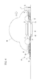
- FIG. 3 is a front view showing a rough structure of the embodiment of the present invention after a removal operation of foreign matter.
- FIG. 4 is a cross-sectional view showing the rough structure of the embodiment of the present invention after removal operation of foreign matter.
- FIG. 5A is a schematic diagram showing working and effect of the embodiment of the present invention.
- FIG. 5B is a schematic diagram showing the working and effect of the embodiment of the present invention.
- FIG. 5C is a schematic diagram showing the working and effect of the embodiment of the present invention.
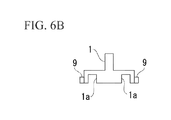
- FIG. 6A is a diagram showing a variant example of the embodiment of the present invention.
- FIG. 6B is a diagram showing the variant example of the embodiment of the present invention.
- FIG. 7A is a front view of a variant example of the embodiment of the present invention.
- FIG. 7B is a diagram showing the variant example of the embodiment of the present invention.
- FIG. 8A is a diagram showing the variant example of the embodiment of the present invention.
- FIG. 8B is a diagram showing the variant example of the embodiment of the present invention.
- FIG. 8C is a diagram showing the variant example of the embodiment of the present invention.
- a foreign matter removal mechanism A is made of: a movable unit 1 ; a movable cleaning unit 2 : a movable frame body 3 ; a first coil spring 4 ; first guide rails 5 ; first stoppers 6 ; a spring fixation unit 7 ; a second coil spring 8 ; second guide rails 9 ; second stoppers 10 , a first foreign matter receiving ditch 11 ; and a second foreign matter receiving ditch 12 , as shown in FIG. 1 and FIG. 2 .
- the foreign matter removal mechanism A is provided in each parking space Ps for a vehicle of a parking lot or the like, and removes foreign matter present on a power-supplying coil K that is buried in the ground surface (parking surface) of the parking space Ps. Namely, the foreign matter removal mechanism A removes foreign matter on the power-supplying coil K, which supplies electric power wirelessly to a power-receiving coil J of a vehicle M parked in the parking space Ps.
- the parking spaces Ps are, for example, rectangular areas provided in a parking lot of a shopping center, each of which is large enough to allow a vehicle M to be parked. As shown in FIG. 1 , the parking space Ps has one of a pair of short sides used as an entrance (exit) for the vehicle M. The vehicle M enters the parking space Ps at the entrance (exit) and exits the parking space Ps to the outside at the entrance (exit).
- the vehicle M charges a rechargeable battery with the electric power that the power-receiving coil J has received wirelessly from the power-supplying coil K, and also utilizes the electric power charged in the rechargeable battery as a power source of a motor for traveling.
- the vehicle M is an electric vehicle or a hybrid vehicle that travels with the wheels driven by the motor.
- the vehicle M is provided with a bumper in its front and rear sections.
- the power-receiving coil J is a helical coil with a predetermined coil diameter.
- the power-receiving coil J is provided in a bottom section of the vehicle M and the coil axis is in a vertical direction.
- the power-receiving coil J has substantially the same coil diameter as that of the power-supplying coil K, which is a ground facility.
- the power-receiving coil J is coupled electromagnetically to the power-supplying coil K, to thereby wirelessly receive power with an alternating current.
- the movable unit 1 is a member formed into a rectangular column, which is arranged so that its height direction is along the vertical direction with respect to the around surface of the parking space Ps.
- the movable unit 1 is held by being sandwiched from both sides between the pair of first guide rails 5 , which are provided along a length direction of the parking space Ps.
- the movable unit 1 has such a height that it contacts with a rear section (for example, a bumper) of the vehicle M entering the parking space Ps.
- a rear section for example, a bumper
- the movable cleaning unit 2 is made of a rectangular plate material. It is a blade member arranged so that its length direction is along a width direction of the parking space Ps and so that its lower edge is set to have the same height as that of an upper surface of the power-supplying coil K.
- the movable cleaning unit 2 has a length with which, when guided by the second guide rails 9 to move as will be described later, the movable cleaning unit 2 is capable of cleaning a whole upper surface of the power-supplying coil K, namely, a whole area through which an electromagnetic field passes as electric power is wirelessly supplied from the power-supplying coil K to the power-receiving coil J.
- the movable cleaning unit 2 is held by being sandwiched from both ends between the pair of second guide rails 9 , which are provided along the length direction of the parking space Ps.
- the movable cleaning unit 2 is connected to the movable unit 1 by means of the first coil spring 4 . Furthermore, the movable cleaning unit 2 has such a height that its upper edge will not contact with the bottom section of the vehicle M.
- this movable cleaning unit 2 is pulled by the movable unit 1 via the first coil spring 4 .
- the movable cleaning unit 2 slides horizontally along the upper surface of the power-supplying coil K. Note that the movable cleaning unit 2 does not have to be formed into a blade, but may have a lower edge in a brush-like shape.
- the movable frame body 3 has a cross-section seen from above in a rectangular ring (hollow cylinder) shape. A first side (a side closer to the first stoppers 6 ) thereof is fixed to the movable cleaning unit 2 from the side opposite to the movable unit 1 , and a pair of sides (a pair of sides parallel to the second guide rails 9 ) thereof are held by being sandwiched between the second guide rails 9 .
- the movable frame body 3 is made as high as possible as far as it will not contact with the bottom surface of the vehicle M. As shown in FIG. 3 and FIG.
- this movable frame body 3 is pulled by the movable unit 1 via the first coil spring 4 .
- the movable frame body 3 slides horizontally along the ground surface of the parking space Ps.
- its top portion may be arranged with a brush-like material or a soft material, so that its contact with the bottom surface of the vehicle M will be softened.
- the first coil spring 4 is an elastic member whose first end is fixed to the movable unit 1 and whose second end is fixed to the movable cleaning unit 2 .
- the first coil spring 4 is arranged along the length direction of the parking space Ps, and is set at a height that it will not contact with the bottom surface of the vehicle M. This first coil spring 4 connects the movable cleaning unit 2 to the movable unit 1 , to thereby couple the movable cleaning unit 2 to the movable unit 1 .
- the first guide rails 5 are installed on the upper surface of the power-supplying coil K. Therefore, to prevent a decrease in the efficiency of wireless power supply, the first guide rails 5 are made of plastic, FRP (Fiber Reinforced Plastic), or the like, which allows an electromagnetic field to pass through, namely, which is non-magnetic and non-conductive.
- the first guide rails 5 are a pair of rails that guide the movable unit 1 .
- the first guide rails 5 are provided on the ground surface of the parking space Ps along the length direction of the parking space Ps, and are positioned at a height that it will not contact with the bottom surface of the vehicle M. It is possible for the movable unit 1 to move reciprocally while being guided by the first guide rails 5 .
- the first stoppers 6 are stoppers dedicated to the movable cleaning unit 2 .
- the first stoppers 6 restrict the movable cleaning unit 2 to a specific position.
- the movable cleaning unit 2 stops moving.
- the first stoppers 6 determine a position of the movable frame body 3 , which moves integrally with the movable cleaning unit 2 .
- the first stoppers 6 also have a function of stopping the movable frame body 3 at a position where the movable frame body 3 surrounds the upper surface of the power-supplying coil K.
- the spring fixation unit 7 is installed on the ground surface of the parking space Ps near its entrance, and fixes a first end of the second coil spring 8 .
- the second coil spring 8 is an elastic member whose first end is fixed to the spring fixation unit 7 and whose second end is fixed to the movable frame body 3 .
- the second coil spring 8 is arranged along the length direction of the parking space Ps, and is installed at a height that it will not contact with the bottom surface of the vehicle M.
- the second coil spring 8 connects the movable frame body 3 to the spring fixation unit 7 , to thereby bias (apply a force to) the movable cleaning unit 2 and the movable frame body 3 in the direction opposite to the direction in which the movable cleaning unit 2 and the movable frame body 3 have moved by the pull from the movable unit 1 .
- the second guide rails 9 are a pair of rails that guide the movable cleaning unit 2 and the movable frame body 3 .
- the second guide rails 9 are provided on the ground surface of the parking space Ps and run by the sides of the power-supplying coil K along the length direction of the parking space Ps.
- the second guide rails 9 are positioned at a height so that they will not contact with the bottom surface of the vehicle M. It is possible for the movable cleaning unit 2 and the movable frame body 3 to move reciprocally while being guided by the second guide rails 9 .
- the second stoppers 10 are stoppers dedicated to the movable frame body 3 .
- the second stoppers 10 restrict the movable frame body 3 , which is biased by the second coil spring 8 , to a specific position. With the movable frame body 3 hitting the second stoppers 10 , the movable cleaning unit 2 and the movable frame body 3 stop their movements by the biasing force from the second coil spring 8 .
- the first foreign matter receiving ditch 11 is a ditch that extends in the same direction as that of the length direction of the movable cleaning unit 2 .
- the first foreign matter receiving ditch 11 is in parallel with the movable cleaning unit 2 , and faces the movable cleaning unit 2 .
- the first foreign matter receiving ditch 11 is arranged on a far side of the power-supplying coil K in the direction in which the movable cleaning unit 2 is moved by the pull from the movable unit 1 .
- the first foreign matter receiving ditch 11 receives foreign matter such as garbage removed from the upper surface of the power-supplying coil.
- the second foreign matter receiving ditch 12 is a ditch that extends in the same direction as that of the length direction of the first foreign matter receiving ditch 11 .
- the second foreign matter receiving ditch 12 is provided on a near side of the power-supplying coil K in the direction in which the movable cleaning unit 2 is moved by the pull from the movable unit 1 .
- the second foreign matter receiving ditch 12 receives foreign matter removed from the ground surface.
- the movable unit 1 contacts with and pushed by the vehicle M as shown in FIG. 3 and FIG. 4 .
- the movable unit 1 is then guided by the first guide rails to move horizontally in the direction opposite to the entrance.
- the movable cleaning unit 2 is pulled by the movable unit 1 via the first coil spring 4 . Therefore, the movable cleaning unit 2 slides horizontally along the upper surface of the power-supplying coil K while being guided by the second guide rails 9 .
- the movable frame body 3 is also pulled by the movable unit 1 via the first coil spring 4 . Therefore, the movable frame body 3 slides horizontally along the ground surface of the parking space Ps while being guided by the second guide rails 9 .
- the movable cleaning unit 2 is located at a position outside the upper surface of the power-supplying coil K; the movable frame body 3 is located at a position that surrounds the upper surface of the power-supplying coil; and the power-receiving coil J of the vehicle M is above the power-supplying coil K, namely, at a position in which electromagnetic coupling is produced to make wireless power supply available.
- the driver drives the vehicle M forward to cause the vehicle M to exit the parking space Ps of the parking space Ps at the exit (entrance), the bumper moves away from the movable unit 1 .
- the movable cleaning unit 2 moving along the upper surface of the power-supplying coil K, it is possible to remove the foreign matter on the power-supplying coil K. Furthermore, according to the embodiment, it is possible to utilize the pushing force from the vehicle M to remove the foreign matter on the power-supplying coil K. This eliminates the necessity of providing a drive source that generates a vibration such as a motor. Furthermore, according to the embodiment, the foreign matter around the power-supplying coil K is removed into the second foreign matter receiving ditch 12 by the movable frame body 3 together with the movable cleaning unit 2 . Therefore, it is possible to prevent the foreign matter around the power-supplying coil K from being moved to the power-supplying coil K.
- the movable frame body 3 surrounds the upper surface of the power-supplying coil K, and the space above the movable frame body 3 is covered with the bottom surface of the vehicle M. This prevents new foreign matter from intruding into the upper surface of the power-supplying coil K.
- the movable cleaning unit 2 slides along the upper surface of the power-supplying coil K.
- the lower edge of the movable cleaning unit 2 may be in a suspended state above the power-supplying coil K, the clearance corresponding to the anticipated size of the foreign matter.
- the movable frame body 3 may be in a suspended state above the ground surface of the parking space Ps.
- the first foreign matter receiving ditch 11 is for receiving the foreign matter having been removed from the upper surface of the power-supplying coil K by the movable cleaning unit 2 .
- the second stoppers 10 are for limiting the range of the reciprocal movements of the movable cleaning unit 2 and the movable frame body 3 , and are not necessarily required to be installed.
- the movable cleaning unit 2 is coupled to the movable unit 1 by the first coil spring 4 .
- the first coil spring 4 anything such as a rope may be used for the coupling so long as, in conjunction with the movement of the movable unit 1 , it moves the movable cleaning unit 2 .
- the second coil spring 8 is used to return the movable cleaning unit 2 and the movable frame body 3 to their default positions after they are moved by the pull from the movable unit 1 .
- the second coil spring 8 is not necessarily required to be installed.
- the movable unit 1 is guided by the first guide rails 5 while the movable cleaning unit 2 and the movable frame body 3 are guided by the second guide rails 9 .
- sliding rollers may be used to make the movements of the movable cleaning unit 2 and the movable frame body 3 possible.
- the vehicle M may be automatically driven without a driver.
- the power-supplying coil K and the power-receiving coil J are not limited to a helical coil. Coils with arbitrary shape and type such as solenoid-type coils may be used so long as they make wireless power supply between the power-supplying coil K and the power-receiving coil J available.
- the two coils may be different in type, shape, and size.
- the cross-sectional view of the movable frame body 3 when seen from above may be other than a rectangle in accordance with the shape of the power-supplying coil.
- the movable unit 1 is guided by the first guide rails 5 , which are positioned above the power-supplying coil K, to be moved horizontally.
- the present invention is not limited to this. For example, as shown in FIG.
- the first guide rails 5 may be omitted, and furthermore, the ends of the second guide rails 9 on the side opposite to the entrance of the parking space Ps may be extended to cover the same length as that of the first guide rails 5 , and the movable unit 1 may be guided by the second guide rails 9 to move horizontally.
- FIG. 6B is a diagram of the movable unit 1 guided by the second guide rails 9 , when seen in the direction opposite to the entrance of the parking space Ps. If guided by the second guide rails 9 , the movable unit 1 is required to be held between the second guide rails 9 . Therefore, as shown in FIG. 6B , the movable unit 1 needs to have a length that covers the distance between the pair of second guide rails 9 .
- this movable unit 1 may be provided with recessed sections 1 a in order to prevent a collision with the first stoppers 6 when the movable unit 1 is moved by the push from the vehicle M in the direction opposite to the entrance of the parking space Ps or when the movable unit 1 is returned to its original position by the pull from the second coil spring 8 as a result of the vehicle M exiting the parking space Ps.
- a first end of the movable cleaning unit 2 may be rotatably supported by a vertical rotation shaft 30 , and a range of rotation of the movable cleaning unit 2 may be restricted by a first stopper 6 and a second stopper 10 , as shown for example in FIG. 7A and FIG. 7B .
- FIG. 7B is a diagram of the movable unit 1 when seen in a direction opposite to the entrance of the parking space Ps.
- the movable unit 1 is supported by a horizontal shaft 31 provided on the second end of the movable cleaning unit 2 and is rotatable about the horizontal shaft 31 with respect to the movable cleaning unit 2 .
- the second end of the second coil spring 8 is fixed to a central portion of the movable cleaning unit 2 .
- the first coil spring 4 has stiffness greater than that of the second coil spring 8 .
- FIG. 8A when the vehicle M enters the parking space Ps, the movable unit 1 is moved by the push from the vehicle M. This causes the movable cleaning unit 2 coupled to the movable unit 1 to rotate about the vertical rotation shaft 30 , to thereby eliminate foreign matter on the power-supplying coil K. Then, as shown in FIG. 8A , when the vehicle M enters the parking space Ps, the movable unit 1 is moved by the push from the vehicle M. This causes the movable cleaning unit 2 coupled to the movable unit 1 to rotate about the vertical rotation shaft 30 , to thereby eliminate foreign matter on the power-supplying coil K. Then, as shown in FIG.
- a foreign matter removal mechanism is provided that is capable of removing foreign matter and that makes it unnecessary to provide a drive source that generates a vibration such as a motor.
Landscapes
- Engineering & Computer Science (AREA)
- Power Engineering (AREA)
- Computer Networks & Wireless Communication (AREA)
- Transportation (AREA)
- Mechanical Engineering (AREA)
- Electric Propulsion And Braking For Vehicles (AREA)
- Charge And Discharge Circuits For Batteries Or The Like (AREA)
- Secondary Cells (AREA)
- Current-Collector Devices For Electrically Propelled Vehicles (AREA)
Abstract
Description
- The present invention relates to a foreign matter removal mechanism.
- This application is a continuation application based on a PCT Patent Application No. PCT/JP2013/068844, filed Jul. 10, 2013, whose priority is claimed on Japanese Patent Application No. 2012-167459, filed Jul. 27, 2012. The contents of both the PCT application and the Japanese Patent Application are incorporated herein by reference.
-
Patent Document 1 below discloses a wireless power-supplying system wherein an insulating separation material is provided in the space between a power-receiving unit provided in a bottom surface of a vehicle and a power-supplying unit buried in a parking space, wherein the separation material is stored under ground except when electric power is supplied, and wherein, when electric power is supplied, the separation material is moved to the space between the power-receiving unit and the power-supplying unit by use of a movable unit, to thereby prevent foreign matter from intruding into the space between the power-receiving unit and the power-supplying unit. Furthermore,Patent Document 2 below discloses a charging device for a vehicle that is provided with a foreign matter removal mechanism made of: a cone section provided on a power-supplying coil; a through-hole that discharges the garbage sliding down on the slope of the cone; and a motor that vibrates the cone. - Patent Document 1: Japanese Unexamined Patent Application, First Publication No. 2010-226946
- Patent Document 2: Japanese Unexamined Patent Application, First Publication No. 2012-85472
- However,
Patent Document 1 as described above has a problem in that, if foreign matter is already present on the power-supplying coil, it is not possible to remove the foreign matter. The foreign matter removal mechanism ofPatent Document 2 as described above leads to increased cost in manufacturing because it is necessary to provide a drive source that generates a vibration such as a motor in order to remove foreign matter. - The present invention is conceived in view of the above-described circumstances, and has objects as follows:
- (1) To be capable of removing foreign matter.
(2) To make it unnecessary to provide a drive source that generates a vibration such as a motor. - To achieve the above objects, a first aspect of a foreign matter removal mechanism of the present invention is a foreign matter removal mechanism for removing foreign matter on a power-supplying coil that wirelessly supplies power to a parked vehicle from below, including: a movable unit that is pushed by the vehicle to move horizontally; and a movable cleaning unit that is coupled to the movable unit and moves, in conjunction with a movement of the movable unit, along an upper surface of the power-supplying coil.
- A second aspect of the present invention is a foreign matter removal mechanism according to the first aspect, including: a foreign matter receiving ditch that is provided on a far side of the power-supplying coil in a moving direction of the movable cleaning unit.
- A third aspect of the present invention is a foreign matter removal mechanism according to the first or second aspect, including: a movable frame body that is fixed to the movable cleaning unit from an opposite side of the movable unit and moves, in conjunction with the movement of the movable unit, along a parking surface on which the vehicle is parked; and a second foreign matter receiving ditch that is provided on a near side of the power-supplying coil in the moving direction of the movable cleaning unit.
- A fourth aspect of the present invention is a foreign matter removal mechanism according to any one of the first to third aspects, including: a stopper provided on the far side of the power-supplying coil in the moving direction of the movable cleaning unit.
- A fifth aspect of the present invention is a foreign matter removal mechanism according to any one of the first to fourth aspects, including: a coil spring that connects between the movable unit and the movable cleaning unit.
- A sixth aspect of the present invention is a foreign matter removal mechanism according to any one of the first to fifth aspects, including: a second stopper that is provided on the near side of the power-supplying coil in the moving direction of the movable cleaning unit; and a second coil spring that biases the movable cleaning unit in a direction opposite to the moving direction of the movable cleaning unit.
- According to the present invention, with the movable cleaning unit moving along the upper surface of the power-supplying coil, it is possible to remove the foreign matter on the power-supplying coil. Furthermore, according to the present invention, it is possible to utilize the pushing force from the vehicle to remove the foreign matter on the power-supplying coil. This eliminates the necessity of providing a drive source that generates a vibration such as a motor.
-
FIG. 1 is a front view showing a rough structure of a foreign matter removal mechanism according to an embodiment of the present invention. -
FIG. 2 is a cross-sectional view showing the rough structure of the embodiment of the present invention. -
FIG. 3 is a front view showing a rough structure of the embodiment of the present invention after a removal operation of foreign matter. -
FIG. 4 is a cross-sectional view showing the rough structure of the embodiment of the present invention after removal operation of foreign matter. -
FIG. 5A is a schematic diagram showing working and effect of the embodiment of the present invention. -
FIG. 5B is a schematic diagram showing the working and effect of the embodiment of the present invention. -
FIG. 5C is a schematic diagram showing the working and effect of the embodiment of the present invention. -
FIG. 6A is a diagram showing a variant example of the embodiment of the present invention. -
FIG. 6B is a diagram showing the variant example of the embodiment of the present invention. -
FIG. 7A is a front view of a variant example of the embodiment of the present invention. -
FIG. 7B is a diagram showing the variant example of the embodiment of the present invention. -
FIG. 8A is a diagram showing the variant example of the embodiment of the present invention. -
FIG. 8B is a diagram showing the variant example of the embodiment of the present invention. -
FIG. 8C is a diagram showing the variant example of the embodiment of the present invention. - Hereunder is a description of an embodiment of the present invention with reference to the drawings.
- A foreign matter removal mechanism A according to the present embodiment is made of: a
movable unit 1; a movable cleaning unit 2: amovable frame body 3; afirst coil spring 4;first guide rails 5;first stoppers 6; aspring fixation unit 7; asecond coil spring 8;second guide rails 9;second stoppers 10, a first foreignmatter receiving ditch 11; and a second foreignmatter receiving ditch 12, as shown inFIG. 1 andFIG. 2 . - As shown in
FIG. 1 , the foreign matter removal mechanism A is provided in each parking space Ps for a vehicle of a parking lot or the like, and removes foreign matter present on a power-supplying coil K that is buried in the ground surface (parking surface) of the parking space Ps. Namely, the foreign matter removal mechanism A removes foreign matter on the power-supplying coil K, which supplies electric power wirelessly to a power-receiving coil J of a vehicle M parked in the parking space Ps. - The parking spaces Ps are, for example, rectangular areas provided in a parking lot of a shopping center, each of which is large enough to allow a vehicle M to be parked. As shown in
FIG. 1 , the parking space Ps has one of a pair of short sides used as an entrance (exit) for the vehicle M. The vehicle M enters the parking space Ps at the entrance (exit) and exits the parking space Ps to the outside at the entrance (exit). - The vehicle M charges a rechargeable battery with the electric power that the power-receiving coil J has received wirelessly from the power-supplying coil K, and also utilizes the electric power charged in the rechargeable battery as a power source of a motor for traveling. The vehicle M is an electric vehicle or a hybrid vehicle that travels with the wheels driven by the motor. The vehicle M is provided with a bumper in its front and rear sections. The power-receiving coil J is a helical coil with a predetermined coil diameter. The power-receiving coil J is provided in a bottom section of the vehicle M and the coil axis is in a vertical direction. The power-receiving coil J has substantially the same coil diameter as that of the power-supplying coil K, which is a ground facility. The power-receiving coil J is coupled electromagnetically to the power-supplying coil K, to thereby wirelessly receive power with an alternating current.
- As shown in
FIG. 1 andFIG. 2 , themovable unit 1 is a member formed into a rectangular column, which is arranged so that its height direction is along the vertical direction with respect to the around surface of the parking space Ps. Themovable unit 1 is held by being sandwiched from both sides between the pair offirst guide rails 5, which are provided along a length direction of the parking space Ps. Furthermore, themovable unit 1 has such a height that it contacts with a rear section (for example, a bumper) of the vehicle M entering the parking space Ps. As shown inFIG. 3 andFIG. 4 , when pushed away from an entrance by the rear section of the vehicle M entering the parking space Ps, thismovable unit 1 is guided by thefirst guide rails 5 to move horizontally in a direction opposite to the entrance. - The
movable cleaning unit 2 is made of a rectangular plate material. It is a blade member arranged so that its length direction is along a width direction of the parking space Ps and so that its lower edge is set to have the same height as that of an upper surface of the power-supplying coil K. Themovable cleaning unit 2 has a length with which, when guided by thesecond guide rails 9 to move as will be described later, themovable cleaning unit 2 is capable of cleaning a whole upper surface of the power-supplying coil K, namely, a whole area through which an electromagnetic field passes as electric power is wirelessly supplied from the power-supplying coil K to the power-receiving coil J. Themovable cleaning unit 2 is held by being sandwiched from both ends between the pair ofsecond guide rails 9, which are provided along the length direction of the parking space Ps. Themovable cleaning unit 2 is connected to themovable unit 1 by means of thefirst coil spring 4. Furthermore, themovable cleaning unit 2 has such a height that its upper edge will not contact with the bottom section of the vehicle M. - As shown in
FIG. 3 andFIG. 4 , with themovable unit 1 being pushed by the vehicle M in the direction opposite to the entrance of the parking space Ps, thismovable cleaning unit 2 is pulled by themovable unit 1 via thefirst coil spring 4. As a result, while being guided by thesecond guide rails 9, themovable cleaning unit 2 slides horizontally along the upper surface of the power-supplying coil K. Note that themovable cleaning unit 2 does not have to be formed into a blade, but may have a lower edge in a brush-like shape. - The
movable frame body 3 has a cross-section seen from above in a rectangular ring (hollow cylinder) shape. A first side (a side closer to the first stoppers 6) thereof is fixed to themovable cleaning unit 2 from the side opposite to themovable unit 1, and a pair of sides (a pair of sides parallel to the second guide rails 9) thereof are held by being sandwiched between the second guide rails 9. Themovable frame body 3 is made as high as possible as far as it will not contact with the bottom surface of the vehicle M. As shown inFIG. 3 andFIG. 4 , with themovable unit 1 being pushed by the vehicle M to be moved in the direction opposite to the entrance of the parking space Ps, thismovable frame body 3 is pulled by themovable unit 1 via thefirst coil spring 4. As a result, while being guided by thesecond guide rails 9, themovable frame body 3 slides horizontally along the ground surface of the parking space Ps. As for themovable frame body 3, its top portion may be arranged with a brush-like material or a soft material, so that its contact with the bottom surface of the vehicle M will be softened. - The
first coil spring 4 is an elastic member whose first end is fixed to themovable unit 1 and whose second end is fixed to themovable cleaning unit 2. Thefirst coil spring 4 is arranged along the length direction of the parking space Ps, and is set at a height that it will not contact with the bottom surface of the vehicle M. Thisfirst coil spring 4 connects themovable cleaning unit 2 to themovable unit 1, to thereby couple themovable cleaning unit 2 to themovable unit 1. - In the present embodiment, the
first guide rails 5 are installed on the upper surface of the power-supplying coil K. Therefore, to prevent a decrease in the efficiency of wireless power supply, thefirst guide rails 5 are made of plastic, FRP (Fiber Reinforced Plastic), or the like, which allows an electromagnetic field to pass through, namely, which is non-magnetic and non-conductive. Thefirst guide rails 5 are a pair of rails that guide themovable unit 1. Thefirst guide rails 5 are provided on the ground surface of the parking space Ps along the length direction of the parking space Ps, and are positioned at a height that it will not contact with the bottom surface of the vehicle M. It is possible for themovable unit 1 to move reciprocally while being guided by the first guide rails 5. - The
first stoppers 6 are stoppers dedicated to themovable cleaning unit 2. When themovable cleaning unit 2 is moved by the pull from themovable unit 1 via thefirst coil spring 4, thefirst stoppers 6 restrict themovable cleaning unit 2 to a specific position. With its hitting thefirst stoppers 6, themovable cleaning unit 2 stops moving. At this time, thefirst stoppers 6 determine a position of themovable frame body 3, which moves integrally with themovable cleaning unit 2. Namely, thefirst stoppers 6 also have a function of stopping themovable frame body 3 at a position where themovable frame body 3 surrounds the upper surface of the power-supplying coil K. - The
spring fixation unit 7 is installed on the ground surface of the parking space Ps near its entrance, and fixes a first end of thesecond coil spring 8. - The
second coil spring 8 is an elastic member whose first end is fixed to thespring fixation unit 7 and whose second end is fixed to themovable frame body 3. Thesecond coil spring 8 is arranged along the length direction of the parking space Ps, and is installed at a height that it will not contact with the bottom surface of the vehicle M. Thesecond coil spring 8 connects themovable frame body 3 to thespring fixation unit 7, to thereby bias (apply a force to) themovable cleaning unit 2 and themovable frame body 3 in the direction opposite to the direction in which themovable cleaning unit 2 and themovable frame body 3 have moved by the pull from themovable unit 1. - The
second guide rails 9 are a pair of rails that guide themovable cleaning unit 2 and themovable frame body 3. Thesecond guide rails 9 are provided on the ground surface of the parking space Ps and run by the sides of the power-supplying coil K along the length direction of the parking space Ps. Thesecond guide rails 9 are positioned at a height so that they will not contact with the bottom surface of the vehicle M. It is possible for themovable cleaning unit 2 and themovable frame body 3 to move reciprocally while being guided by the second guide rails 9. - The
second stoppers 10 are stoppers dedicated to themovable frame body 3. Thesecond stoppers 10 restrict themovable frame body 3, which is biased by thesecond coil spring 8, to a specific position. With themovable frame body 3 hitting thesecond stoppers 10, themovable cleaning unit 2 and themovable frame body 3 stop their movements by the biasing force from thesecond coil spring 8. - The first foreign
matter receiving ditch 11 is a ditch that extends in the same direction as that of the length direction of themovable cleaning unit 2. The first foreignmatter receiving ditch 11 is in parallel with themovable cleaning unit 2, and faces themovable cleaning unit 2. The first foreignmatter receiving ditch 11 is arranged on a far side of the power-supplying coil K in the direction in which themovable cleaning unit 2 is moved by the pull from themovable unit 1. When themovable cleaning unit 2 slides on the upper surface of the power-supplying coil by the pull from themovable unit 1 via thefirst coil spring 4, the first foreignmatter receiving ditch 11 receives foreign matter such as garbage removed from the upper surface of the power-supplying coil. - The second foreign
matter receiving ditch 12 is a ditch that extends in the same direction as that of the length direction of the first foreignmatter receiving ditch 11. The second foreignmatter receiving ditch 12 is provided on a near side of the power-supplying coil K in the direction in which themovable cleaning unit 2 is moved by the pull from themovable unit 1. When themovable frame body 3 slides on the ground surface of the parking space Ps by the pull from themovable unit 1 via thefirst coil spring 4, the second foreignmatter receiving ditch 12 receives foreign matter removed from the ground surface. - A detailed description of working and effect of the foreign matter removal mechanism A with the above-described structure will be given below, with reference to
FIG. 5A ,FIG. 5B , andFIG. 5C . Note that the following description will be for the case where the vehicle M rolls backward to enter and park in the parking space Ps. - When trying to park the vehicle M in the parking space Ps, a driver drives the vehicle M backward to cause the vehicle M to enter the parking space Ps at the entrance of the parking space Ps. When the vehicle M rolls straightly backward into the parking space Ps at the entrance, the bumper contacts with the
movable unit 1. - In the foreign matter removal mechanism A, when the vehicle M enters the parking space Ps in this manner in order to park, the
movable unit 1 contacts with and pushed by the vehicle M as shown inFIG. 3 andFIG. 4 . Themovable unit 1 is then guided by the first guide rails to move horizontally in the direction opposite to the entrance. As a result, themovable cleaning unit 2 is pulled by themovable unit 1 via thefirst coil spring 4. Therefore, themovable cleaning unit 2 slides horizontally along the upper surface of the power-supplying coil K while being guided by the second guide rails 9. Similarly, together with themovable cleaning unit 2, themovable frame body 3 is also pulled by themovable unit 1 via thefirst coil spring 4. Therefore, themovable frame body 3 slides horizontally along the ground surface of the parking space Ps while being guided by the second guide rails 9. - Suppose that, before the vehicle M enters the parking space Ps, foreign matter is present on the power-supplying coil K and also that another foreign matter is present on the ground surface in the
movable frame body 3, as shown inFIG. 5A . When the vehicle M starts to push themovable unit 1 after entering the parking space Ps, themovable cleaning unit 2, while being moved, moves the foreign matter on the power-supplying coil K toward the first foreignmatter receiving ditch 11, as shown inFIG. 5B . On the other hand, themovable frame body 3, while being moved, moves the foreign matter on the ground surface in themovable frame body 3 toward the second foreignmatter receiving ditch 12. After that, when themovable cleaning unit 2 hits thefirst stoppers 6, the movements of themovable cleaning unit 2 and themovable frame body 3 stop. Then, as is shown inFIG. 5C , the foreign matter on the power-supplying coil K is received in the first foreignmatter receiving ditch 11 while the foreign matter on the ground surface in themovable frame body 3 is received in the second foreignmatter receiving ditch 12. At this time, themovable cleaning unit 2 is located at a position outside the upper surface of the power-supplying coil K; themovable frame body 3 is located at a position that surrounds the upper surface of the power-supplying coil; and the power-receiving coil J of the vehicle M is above the power-supplying coil K, namely, at a position in which electromagnetic coupling is produced to make wireless power supply available. - After that, in the case of starting the vehicle M from the parking space Ps, the driver drives the vehicle M forward to cause the vehicle M to exit the parking space Ps of the parking space Ps at the exit (entrance), the bumper moves away from the
movable unit 1. - In the case of the foreign matter removal mechanism A, when the vehicle M exits from the parking space Ps in this manner after parking, the pull of the
movable cleaning unit 2 and themovable frame body 3 by themovable unit 1 is released. Therefore, themovable cleaning unit 2 and themovable frame body 3 are moved in the direction of thespring fixation unit 7 by a biasing force of thesecond coil spring 8. Then, with themovable frame body 3 hitting thesecond stoppers 10, themovable cleaning unit 2 and themovable frame body 3 stop the movements by the biasing force of thesecond coil spring 8 to return to the default positions, as shown inFIG. 1 andFIG. 2 . - According to this embodiment, with the
movable cleaning unit 2 moving along the upper surface of the power-supplying coil K, it is possible to remove the foreign matter on the power-supplying coil K. Furthermore, according to the embodiment, it is possible to utilize the pushing force from the vehicle M to remove the foreign matter on the power-supplying coil K. This eliminates the necessity of providing a drive source that generates a vibration such as a motor. Furthermore, according to the embodiment, the foreign matter around the power-supplying coil K is removed into the second foreignmatter receiving ditch 12 by themovable frame body 3 together with themovable cleaning unit 2. Therefore, it is possible to prevent the foreign matter around the power-supplying coil K from being moved to the power-supplying coil K. In addition, in a state with the foreign matter inside themovable frame body 3 being removed, themovable frame body 3 surrounds the upper surface of the power-supplying coil K, and the space above themovable frame body 3 is covered with the bottom surface of the vehicle M. This prevents new foreign matter from intruding into the upper surface of the power-supplying coil K. - The present invention is not limited to the above-mentioned embodiment, and for instance the following variant examples are conceivable:
- (1) In the above-mentioned embodiment, the
movable cleaning unit 2 slides along the upper surface of the power-supplying coil K. However, instead of being in contact with the power-supplying coil K, the lower edge of themovable cleaning unit 2 may be in a suspended state above the power-supplying coil K, the clearance corresponding to the anticipated size of the foreign matter. Similarly, themovable frame body 3 may be in a suspended state above the ground surface of the parking space Ps.
(2) In the above-mentioned embodiment, the first foreignmatter receiving ditch 11 is for receiving the foreign matter having been removed from the upper surface of the power-supplying coil K by themovable cleaning unit 2. Therefore, if only the foreign matter on the power-supplying coil K is to be removed by themovable cleaning unit 2, it is not necessarily required to install the first foreignmatter receiving ditch 11. This is also true of themovable frame body 3 and the second foreignmatter receiving ditch 12, which are installed for receiving the foreign matter around the power-supplying coil K, and are not necessarily required to be installed. In the case where themovable frame body 3 is not installed, thesecond coil spring 8 may be fixed to themovable cleaning unit 2 instead of fixed to themovable frame body 3.
(3) In the above-mentioned embodiment, thesecond stoppers 10 are for limiting the range of the reciprocal movements of themovable cleaning unit 2 and themovable frame body 3, and are not necessarily required to be installed.
(4) In the above-mentioned embodiment, themovable cleaning unit 2 is coupled to themovable unit 1 by thefirst coil spring 4. However, instead of thefirst coil spring 4, anything such as a rope may be used for the coupling so long as, in conjunction with the movement of themovable unit 1, it moves themovable cleaning unit 2. Further more, thesecond coil spring 8 is used to return themovable cleaning unit 2 and themovable frame body 3 to their default positions after they are moved by the pull from themovable unit 1. However, so long as themovable cleaning unit 2 and themovable frame body 3 are returned to their default positions by use of another means, thesecond coil spring 8 is not necessarily required to be installed.
(5) In the above-mentioned embodiment, themovable unit 1 is guided by thefirst guide rails 5 while themovable cleaning unit 2 and themovable frame body 3 are guided by the second guide rails 9. However, instead of these guide rails, sliding rollers may be used to make the movements of themovable cleaning unit 2 and themovable frame body 3 possible.
(6) The vehicle M may be automatically driven without a driver.
(7) The power-supplying coil K and the power-receiving coil J are not limited to a helical coil. Coils with arbitrary shape and type such as solenoid-type coils may be used so long as they make wireless power supply between the power-supplying coil K and the power-receiving coil J available. Further more, the two coils may be different in type, shape, and size. Also, the cross-sectional view of themovable frame body 3 when seen from above may be other than a rectangle in accordance with the shape of the power-supplying coil.
(8) In the above-mentioned embodiment, themovable unit 1 is guided by thefirst guide rails 5, which are positioned above the power-supplying coil K, to be moved horizontally. However, the present invention is not limited to this. For example, as shown inFIG. 6A , thefirst guide rails 5 may be omitted, and furthermore, the ends of thesecond guide rails 9 on the side opposite to the entrance of the parking space Ps may be extended to cover the same length as that of thefirst guide rails 5, and themovable unit 1 may be guided by thesecond guide rails 9 to move horizontally. -
FIG. 6B is a diagram of themovable unit 1 guided by thesecond guide rails 9, when seen in the direction opposite to the entrance of the parking space Ps. If guided by thesecond guide rails 9, themovable unit 1 is required to be held between the second guide rails 9. Therefore, as shown inFIG. 6B , themovable unit 1 needs to have a length that covers the distance between the pair of second guide rails 9. Furthermore, thismovable unit 1 may be provided with recessedsections 1 a in order to prevent a collision with thefirst stoppers 6 when themovable unit 1 is moved by the push from the vehicle M in the direction opposite to the entrance of the parking space Ps or when themovable unit 1 is returned to its original position by the pull from thesecond coil spring 8 as a result of the vehicle M exiting the parking space Ps. - (9) Other than the above-mentioned variant examples, a first end of the
movable cleaning unit 2 may be rotatably supported by avertical rotation shaft 30, and a range of rotation of themovable cleaning unit 2 may be restricted by afirst stopper 6 and asecond stopper 10, as shown for example inFIG. 7A andFIG. 7B .FIG. 7B is a diagram of themovable unit 1 when seen in a direction opposite to the entrance of the parking space Ps. InFIG. 7B , themovable unit 1 is supported by ahorizontal shaft 31 provided on the second end of themovable cleaning unit 2 and is rotatable about thehorizontal shaft 31 with respect to themovable cleaning unit 2. Furthermore, the second end of thesecond coil spring 8 is fixed to a central portion of themovable cleaning unit 2. Note that thefirst coil spring 4 has stiffness greater than that of thesecond coil spring 8. - Hereunder, a description of a process is given in which the vehicle M enters and parks in the parking space Ps when the variant example shown in
FIG. 7A is used, with reference toFIG. 8A ,FIG. 8B , andFIG. 8C . As shown inFIG. 8A , when the vehicle M enters the parking space Ps, themovable unit 1 is moved by the push from the vehicle M. This causes themovable cleaning unit 2 coupled to themovable unit 1 to rotate about thevertical rotation shaft 30, to thereby eliminate foreign matter on the power-supplying coil K. Then, as shown inFIG. 8B , when the vehicle M enters the parking space Ps further, the foreign matter eliminated by themovable cleaning unit 2 falls into the first foreignmatter receiving ditch 11, and then themovable cleaning unit 2 hits thefirst stopper 6. When the vehicle M enters the parking space Ps still further to be located at a position where wireless power supply is available, namely, when the power-receiving coil J of the vehicle M is above the power-supplying coil K as shown inFIG. 8C then themovable unit 1 falls to the ground and goes under the vehicle M. When the wireless power supply is completed and the vehicle M is moving away from the parking space Ps, themovable unit 1 is returned to its erect state due to the restoring force of thefirst coil spring 4. When the vehicle M is moving further away from the parking space Ps, themovable cleaning unit 2 is returned to a position where themovable cleaning unit 2 hits thesecond stopper 10 due to the restoring force of thesecond coil spring 8. - A foreign matter removal mechanism is provided that is capable of removing foreign matter and that makes it unnecessary to provide a drive source that generates a vibration such as a motor.
-
- A: foreign matter removal mechanism
- 1: movable unit
- 2: movable cleaning unit
- 3: movable frame body
- 4: first coil spring
- 5: first guide rail
- 6: first stopper
- 7: spring fixation unit
- 8: second coil spring
- 9: second guide rail
- 10: second stopper
- 11: first foreign matter receiving ditch
- 12: second foreign matter receiving ditch
- 1 a: recessed section
Claims (6)
Applications Claiming Priority (3)
| Application Number | Priority Date | Filing Date | Title |
|---|---|---|---|
| JP2012167459A JP5974710B2 (en) | 2012-07-27 | 2012-07-27 | Foreign matter removal mechanism |
| JP2012-167459 | 2012-07-27 | ||
| PCT/JP2013/068844 WO2014017296A1 (en) | 2012-07-27 | 2013-07-10 | Foreign-object removal mechanism |
Related Parent Applications (1)
| Application Number | Title | Priority Date | Filing Date |
|---|---|---|---|
| PCT/JP2013/068844 Continuation WO2014017296A1 (en) | 2012-07-27 | 2013-07-10 | Foreign-object removal mechanism |
Publications (2)
| Publication Number | Publication Date |
|---|---|
| US20150128362A1 true US20150128362A1 (en) | 2015-05-14 |
| US9248475B2 US9248475B2 (en) | 2016-02-02 |
Family
ID=49997112
Family Applications (1)
| Application Number | Title | Priority Date | Filing Date |
|---|---|---|---|
| US14/597,719 Active US9248475B2 (en) | 2012-07-27 | 2015-01-15 | Foreign matter removal mechanism |
Country Status (5)
| Country | Link |
|---|---|
| US (1) | US9248475B2 (en) |
| EP (1) | EP2879272B1 (en) |
| JP (1) | JP5974710B2 (en) |
| CN (1) | CN104428977B (en) |
| WO (1) | WO2014017296A1 (en) |
Cited By (7)
| Publication number | Priority date | Publication date | Assignee | Title |
|---|---|---|---|---|
| US20170182903A1 (en) * | 2015-12-26 | 2017-06-29 | Intel Corporation | Technologies for wireless charging of electric vehicles |
| CN110091736A (en) * | 2019-04-28 | 2019-08-06 | 合芯磁导科技(无锡)有限公司 | A kind of foreign matter method for cleaning of intelligent radio charging transmitting protector |
| US10377254B2 (en) * | 2013-05-14 | 2019-08-13 | Ihi Corporation | Wireless power transmission device and vehicle |
| CN110168858A (en) * | 2017-02-09 | 2019-08-23 | 松下知识产权经营株式会社 | The control method and power transmission device of power transmission device in Wireless power transmission system |
| US20210001911A1 (en) * | 2019-07-02 | 2021-01-07 | Toshiba Tec Kabushiki Kaisha | Power receiving device, power supply device, and power supply system |
| US11329520B2 (en) * | 2018-07-31 | 2022-05-10 | Panasonic Intellectual Property Management Co., Ltd. | Power transmission device, power reception device, wireless power transmission system, and method for driving power transmission device |
| CN117123538A (en) * | 2023-09-11 | 2023-11-28 | 广西电网有限责任公司电力科学研究院 | Foreign object removal device in wireless charging area |
Families Citing this family (17)
| Publication number | Priority date | Publication date | Assignee | Title |
|---|---|---|---|---|
| JP6310278B2 (en) * | 2014-02-28 | 2018-04-11 | 矢崎総業株式会社 | Power supply unit and power supply system |
| JP6512024B2 (en) * | 2015-08-10 | 2019-05-15 | Tdk株式会社 | Contactless power supply device and contactless power transmission device |
| JP6544129B2 (en) * | 2015-08-10 | 2019-07-17 | Tdk株式会社 | Contactless power supply device and contactless power transmission device |
| JP6478883B2 (en) * | 2015-09-10 | 2019-03-06 | 大日本印刷株式会社 | Liquid crystal display |
| JP6868984B2 (en) * | 2016-08-29 | 2021-05-12 | 日本無線株式会社 | Foreign matter intervention prevention device |
| JP6956474B2 (en) * | 2016-08-29 | 2021-11-02 | 日本無線株式会社 | Power transmission relay device |
| CN107591903A (en) * | 2017-09-05 | 2018-01-16 | 中惠创智无线供电技术有限公司 | Foreign matter for electric power wireless transmitting system removes equipment and its application method |
| US11066973B2 (en) * | 2018-07-10 | 2021-07-20 | Cummins Emission Solutions Inc. | Heating system for a tank header of aftertreatment system and method of heating a tank header |
| CN111216573B (en) * | 2018-11-27 | 2023-08-04 | 青岛海汇德电气有限公司 | Charging system of electric automobile |
| CN110027426A (en) * | 2019-04-17 | 2019-07-19 | 合芯磁导科技(无锡)有限公司 | A kind of cleaning structure of intelligent radio charging transmitter |
| CN110015001B (en) * | 2019-04-28 | 2022-06-24 | 合芯磁导科技(无锡)有限公司 | Intelligent wireless charger |
| JP7366655B2 (en) * | 2019-09-10 | 2023-10-23 | 東芝テック株式会社 | Contactless power supply system and power transmission equipment |
| CN113335089A (en) * | 2021-06-26 | 2021-09-03 | 深圳欣锐科技股份有限公司 | Electric energy receiving platform, charging system and vehicle |
| CN114285130B (en) * | 2021-12-28 | 2023-06-27 | 岳阳市东颂电子有限公司 | Portable power source convenient to accomodate charging wire |
| CN115284918B (en) * | 2022-07-15 | 2025-12-02 | 杭州海康汽车软件有限公司 | A parking system, method and apparatus |
| JP7412034B1 (en) | 2022-11-02 | 2024-01-12 | 鈴木製機株式会社 | Conveyance system |
| JP7481033B1 (en) | 2022-11-02 | 2024-05-10 | 鈴木製機株式会社 | Conveyor system, vertical conveyor |
Family Cites Families (11)
| Publication number | Priority date | Publication date | Assignee | Title |
|---|---|---|---|---|
| US4368554A (en) * | 1980-03-28 | 1983-01-18 | Hestair Eagle Limited | Road sweeping apparatus |
| US4506405A (en) * | 1983-09-29 | 1985-03-26 | Mcgraw-Edison Company | Floor treating machine |
| JP3772997B2 (en) * | 1995-07-31 | 2006-05-10 | 住友電装株式会社 | Electric vehicle charging system and electromagnetic coupling device for electric vehicle charging |
| US5983442A (en) * | 1997-06-06 | 1999-11-16 | The Hoover Company | Carpet extractor with automatic conversion |
| US6131237A (en) * | 1997-07-09 | 2000-10-17 | Bissell Homecare, Inc. | Upright extraction cleaning machine |
| US20050146222A1 (en) * | 2002-02-26 | 2005-07-07 | Hulden Richard M. | Direct current portable power supply |
| JP4420073B2 (en) * | 2007-07-11 | 2010-02-24 | セイコーエプソン株式会社 | Coil unit and electronic equipment |
| CN103259344B (en) * | 2007-12-21 | 2016-08-10 | 捷通国际有限公司 | Circuit for induced power transmission |
| US20110074346A1 (en) * | 2009-09-25 | 2011-03-31 | Hall Katherine L | Vehicle charger safety system and method |
| JP5606098B2 (en) * | 2009-02-25 | 2014-10-15 | マスプロ電工株式会社 | Mobile power supply system |
| JP5574107B2 (en) * | 2010-10-13 | 2014-08-20 | 三菱自動車工業株式会社 | Vehicle charging device |
-
2012
- 2012-07-27 JP JP2012167459A patent/JP5974710B2/en not_active Expired - Fee Related
-
2013
- 2013-07-10 CN CN201380037533.0A patent/CN104428977B/en not_active Expired - Fee Related
- 2013-07-10 EP EP13823102.2A patent/EP2879272B1/en not_active Not-in-force
- 2013-07-10 WO PCT/JP2013/068844 patent/WO2014017296A1/en not_active Ceased
-
2015
- 2015-01-15 US US14/597,719 patent/US9248475B2/en active Active
Cited By (8)
| Publication number | Priority date | Publication date | Assignee | Title |
|---|---|---|---|---|
| US10377254B2 (en) * | 2013-05-14 | 2019-08-13 | Ihi Corporation | Wireless power transmission device and vehicle |
| US20170182903A1 (en) * | 2015-12-26 | 2017-06-29 | Intel Corporation | Technologies for wireless charging of electric vehicles |
| CN110168858A (en) * | 2017-02-09 | 2019-08-23 | 松下知识产权经营株式会社 | The control method and power transmission device of power transmission device in Wireless power transmission system |
| US11329520B2 (en) * | 2018-07-31 | 2022-05-10 | Panasonic Intellectual Property Management Co., Ltd. | Power transmission device, power reception device, wireless power transmission system, and method for driving power transmission device |
| US11804736B2 (en) | 2018-07-31 | 2023-10-31 | Panasonic Intellectual Property Management Co., Ltd. | Power transmission device, power reception device, wireless power transmission system, and method for driving power transmission device |
| CN110091736A (en) * | 2019-04-28 | 2019-08-06 | 合芯磁导科技(无锡)有限公司 | A kind of foreign matter method for cleaning of intelligent radio charging transmitting protector |
| US20210001911A1 (en) * | 2019-07-02 | 2021-01-07 | Toshiba Tec Kabushiki Kaisha | Power receiving device, power supply device, and power supply system |
| CN117123538A (en) * | 2023-09-11 | 2023-11-28 | 广西电网有限责任公司电力科学研究院 | Foreign object removal device in wireless charging area |
Also Published As
| Publication number | Publication date |
|---|---|
| EP2879272A1 (en) | 2015-06-03 |
| JP2014027813A (en) | 2014-02-06 |
| JP5974710B2 (en) | 2016-08-23 |
| EP2879272A4 (en) | 2017-01-04 |
| CN104428977A (en) | 2015-03-18 |
| WO2014017296A1 (en) | 2014-01-30 |
| EP2879272B1 (en) | 2017-09-06 |
| CN104428977B (en) | 2017-03-08 |
| US9248475B2 (en) | 2016-02-02 |
Similar Documents
| Publication | Publication Date | Title |
|---|---|---|
| US9248475B2 (en) | Foreign matter removal mechanism | |
| EP2887498B1 (en) | Moving parking facility | |
| US9027723B2 (en) | Vehicle electric power supply system | |
| CN203543864U (en) | Electromagnetic car crash damping device | |
| CN103857553A (en) | Charging station | |
| CN104488162A (en) | Contactless power-supply system | |
| JP5582074B2 (en) | Vehicle, automatic parking support equipment and automatic parking system | |
| CN104508946A (en) | Vehicle power feeding device | |
| WO2014038691A1 (en) | Vehicle power feeding device | |
| CN102418427B (en) | Vehicle bearing plate of multi-storied garage is to level detecting apparatus | |
| JP2011250593A (en) | Vehicle | |
| CN212861113U (en) | Non-contact charging device | |
| KR101828160B1 (en) | Catenary free tram system | |
| CN111347885A (en) | Intelligent rail wireless public transport trolley system | |
| CN103889774B (en) | There is the vehicle of electric driver | |
| KR20130075580A (en) | Guide way type electric charging system | |
| JP4774066B2 (en) | Charging system | |
| JP6172916B2 (en) | Vehicle power supply device | |
| JP2013201876A (en) | Electric power supply coil positioning mechanism | |
| CN110481355B (en) | A charging device for electric power selling's installation of being convenient for | |
| KR101452571B1 (en) | An electric vehicle charging system | |
| KR101281731B1 (en) | Park-and-ride system and method with charging facility | |
| JP2011068196A (en) | Vehicle conveying facilities on expressway | |
| KR20130029198A (en) | Charging and generating system for electric vehicle | |
| JP2007124806A (en) | Automatic charger of motor-driven track lorry |
Legal Events
| Date | Code | Title | Description |
|---|---|---|---|
| AS | Assignment |
Owner name: IHI CORPORATION, JAPAN Free format text: ASSIGNMENT OF ASSIGNORS INTEREST;ASSIGNOR:NIIZUMA, MOTONAO;REEL/FRAME:034728/0399 Effective date: 20150105 |
|
| STCF | Information on status: patent grant |
Free format text: PATENTED CASE |
|
| MAFP | Maintenance fee payment |
Free format text: PAYMENT OF MAINTENANCE FEE, 4TH YEAR, LARGE ENTITY (ORIGINAL EVENT CODE: M1551); ENTITY STATUS OF PATENT OWNER: LARGE ENTITY Year of fee payment: 4 |
|
| MAFP | Maintenance fee payment |
Free format text: PAYMENT OF MAINTENANCE FEE, 8TH YEAR, LARGE ENTITY (ORIGINAL EVENT CODE: M1552); ENTITY STATUS OF PATENT OWNER: LARGE ENTITY Year of fee payment: 8 |