US20060088323A1 - Design support program and design support method - Google Patents
Design support program and design support method Download PDFInfo
- Publication number
- US20060088323A1 US20060088323A1 US11/258,499 US25849905A US2006088323A1 US 20060088323 A1 US20060088323 A1 US 20060088323A1 US 25849905 A US25849905 A US 25849905A US 2006088323 A1 US2006088323 A1 US 2006088323A1
- Authority
- US
- United States
- Prior art keywords
- virtual
- procedure
- sheet
- jam
- design support
- Prior art date
- Legal status (The legal status is an assumption and is not a legal conclusion. Google has not performed a legal analysis and makes no representation as to the accuracy of the status listed.)
- Abandoned
Links
- 238000000034 method Methods 0.000 title claims abstract description 96
- 238000013461 design Methods 0.000 title claims abstract description 75
- 230000007246 mechanism Effects 0.000 claims abstract description 67
- 238000012545 processing Methods 0.000 claims abstract description 38
- 238000012795 verification Methods 0.000 claims abstract description 18
- 230000008569 process Effects 0.000 claims abstract description 11
- 238000004088 simulation Methods 0.000 description 67
- 238000004364 calculation method Methods 0.000 description 25
- 238000010586 diagram Methods 0.000 description 15
- 238000012544 monitoring process Methods 0.000 description 9
- 238000011144 upstream manufacturing Methods 0.000 description 4
- 230000002159 abnormal effect Effects 0.000 description 3
- 230000008859 change Effects 0.000 description 2
- 230000007547 defect Effects 0.000 description 2
- 239000003550 marker Substances 0.000 description 2
- 239000003086 colorant Substances 0.000 description 1
- 238000001514 detection method Methods 0.000 description 1
- 238000005516 engineering process Methods 0.000 description 1
- 238000004519 manufacturing process Methods 0.000 description 1
- 230000008439 repair process Effects 0.000 description 1
- 230000004044 response Effects 0.000 description 1
- 230000007306 turnover Effects 0.000 description 1
Images


Classifications
-
- G—PHYSICS
- G03—PHOTOGRAPHY; CINEMATOGRAPHY; ANALOGOUS TECHNIQUES USING WAVES OTHER THAN OPTICAL WAVES; ELECTROGRAPHY; HOLOGRAPHY
- G03G—ELECTROGRAPHY; ELECTROPHOTOGRAPHY; MAGNETOGRAPHY
- G03G15/00—Apparatus for electrographic processes using a charge pattern
- G03G15/50—Machine control of apparatus for electrographic processes using a charge pattern, e.g. regulating differents parts of the machine, multimode copiers, microprocessor control
- G03G15/5012—Priority interrupt; Job recovery, e.g. after jamming or malfunction
-
- G—PHYSICS
- G03—PHOTOGRAPHY; CINEMATOGRAPHY; ANALOGOUS TECHNIQUES USING WAVES OTHER THAN OPTICAL WAVES; ELECTROGRAPHY; HOLOGRAPHY
- G03G—ELECTROGRAPHY; ELECTROPHOTOGRAPHY; MAGNETOGRAPHY
- G03G2215/00—Apparatus for electrophotographic processes
- G03G2215/00362—Apparatus for electrophotographic processes relating to the copy medium handling
- G03G2215/00535—Stable handling of copy medium
- G03G2215/00548—Jam, error detection, e.g. double feeding
Definitions
- the present invention relates to a design support program and a design support method for supporting a mechanism control design.
- this relates to a design support program and a design support method of software for controlling a conveying mechanism for conveying a sheet-like conveyed object.
- a sheet-like conveyed object such as paper (hereafter, this is simply called a sheet)
- a sheet is conveyed by a conveying mechanism such as a roller and a guide.
- the invention described in the above-mentioned Japanese Patent Application Laid-Open No. H05-143260 generates a jam by an operator pushing a keyboard in suitable timing while making printer control software perform simulation operation. Hence, it is not possible to reproduce correctly the verification of operation at the time of jam occurrence which is important at the time of a design of software which controls a sheet conveying mechanism.
- the present invention aims at providing a design support program and a design support method which perform easily the operation verification of conveying mechanism control software at the time of an abnormal condition such as jam occurrence.
- a design support program of the present invention is characterized by making a computer execute a first procedure of setting jam occurrence conditions of a virtual sheet beforehand, a second procedure of judging whether the above-mentioned jam occurrence conditions set in the above-mentioned first procedure are satisfied, and a third procedure of stopping the conveyance of the virtual sheet when it is judged that the above-mentioned jam occurrence conditions are satisfied in the above-mentioned second procedure.
- a design support method of the present invention is characterized by comprising a first procedure of setting jam occurrence conditions of a virtual sheet beforehand, a second procedure of judging whether the above-mentioned jam occurrence conditions set in the above-mentioned first procedure are satisfied, and a third procedure of stopping the conveyance of the virtual sheet when it is judged in the above-mentioned second procedure that the above-mentioned jam occurrence conditions are satisfied.
- a design support program of the present invention is characterized by making a computer execute a first procedure of setting failure occurrence conditions of a virtual device beforehand, a second procedure of judging whether the above-mentioned failure occurrence conditions set in the above-mentioned first procedure are satisfied, and a third procedure of generating a failure of a virtual device when it is judged in the above-mentioned second procedure that the above-mentioned failure occurrence conditions are satisfied.
- a design support method of the present invention is characterized by comprising a first procedure of setting failure occurrence conditions of a virtual device beforehand, a second procedure of judging whether the above-mentioned failure occurrence conditions set in the above-mentioned first procedure are satisfied, and a third procedure of generating a failure of a virtual device when it is judged in the above-mentioned second procedure that the above-mentioned failure occurrence conditions are satisfied.
- FIG. 1 is a system general view in a first embodiment
- FIG. 2 is a screen shot of a design support apparatus in the first embodiment
- FIG. 3 is a jam condition setting screen shot in the first embodiment
- FIG. 4 is an image drawing of a jam setting condition in the first embodiment
- FIG. 5 is a software block diagram in the first embodiment
- FIG. 6 is a flowchart of jam occurrence in the first embodiment
- FIG. 7 is a flowchart of a sheet position calculation portion by a design support method in the first embodiment
- FIG. 8 is a schematic diagram of mechanism simulation of the design support apparatus in the first embodiment
- FIG. 9 is a flow chart showing an example of conveyance control in the first embodiment
- FIG. 10 is a software block diagram in a second embodiment
- FIG. 11 is a flowchart of jam processing in the second embodiment
- FIG. 12 is a flowchart of a sheet position calculation portion by a design support method in the second embodiment
- FIG. 13 is an image drawing of displaying jam information in a jam information display portion in the second embodiment as a warning message
- FIG. 14 is an image drawing of displaying jam information in a jam information display portion in the second embodiment with changing colors and shapes;
- FIG. 15 is a control block diagram of a design support apparatus of a third embodiment
- FIG. 16 is a drawing showing an operating portion of an image forming apparatus in the third embodiment.
- FIG. 17 is a jam condition setting screen shot in the third embodiment.
- FIG. 18 is a software block diagram in the third embodiment
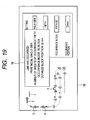
- FIG. 19 is an image drawing of displaying jam information in the third embodiment.
- FIG. 20 is a software block diagram in a fourth embodiment
- FIG. 21 is a device failure setting screen shot in the fourth embodiment.
- FIG. 22 is a flowchart of device failure occurrence processing in the fourth embodiment.
- FIG. 23 is an explanatory diagram of a roller OFF state failure in the forth embodiment
- FIG. 24 is a flow chart showing an example of control at the time of a roller OFF failure in the fourth embodiment
- FIG. 25 is an explanatory diagram of a roller ON state failure in the forth embodiment
- FIG. 26 is a flow chart showing an example of control at the time of a roller ON failure in the fourth embodiment
- FIG. 27 is an explanatory diagram of a sensor OFF state failure in the forth embodiment
- FIG. 28 is an explanatory diagram of a sensor ON state failure in the forth embodiment
- FIG. 29 is a flow chart showing an example of control at the time of a sensor ON failure in the fourth embodiment.
- FIG. 30 is a flow chart showing an example of control at the time of a sensor stay/jam processing in the fourth embodiment
- FIG. 31 is an explanatory diagram of a motor OFF state failure in the forth embodiment
- FIG. 32 is an explanatory diagram of a motor ON state failure in the forth embodiment
- FIGS. 33A, 33B and 33 C are explanatory diagrams of plural locations of device failures in the fourth embodiment
- FIG. 34 is a software block diagram in a fifth embodiment
- FIG. 35 is a display image drawing of a device failure condition setting screen in the fifth embodiment.
- FIG. 36 is a display image drawing of a warning screen of a design support apparatus in the fifth embodiment.
- FIG. 1 shows a design support apparatus according to this embodiment.
- the design support apparatus of this embodiment is a sheet conveyance simulator which can perform the sheet conveying simulation of an image forming apparatus on a personal computer.
- this supports a control timing design of firm software which controls an image forming apparatus in the real world, and makes it possible to verify the processing operation of the firm software.
- a software simulation portion 1 is a portion for executing firm software about sheet conveyance control virtually on a personal computer.
- An input monitoring portion 4 monitors an input of a keyboard device and a mouse which are man machine interfaces.
- the above-mentioned software simulation portion 1 starts software simulation control in response to an execution start request from the above-mentioned input monitoring portion 4 .
- the execution result of software simulation is passed to a mechanism simulation portion 2 .
- the mechanism simulation portion 2 obtains in what part within a sheet conveying mechanism a virtual sheet exists from the velocity of a virtual roller in connection with sheet conveyance control, and the like by calculation. Then, positional information of the virtual sheet which is obtained is passed to the software simulation portion 1 or a display control portion 5 .
- FIG. 2 shows a display example of a sheet conveying simulation screen W 1 shown on a display accompanying a personal computer by the display control portion 5 .
- a virtual sheet conveying path and a virtual roller are shown by a dotted line and a circle respectively, and a virtual sensor and a virtual sheet are shown by a triangle and a continuous line respectively.
- a jam condition setting screen W 2 as shown in FIG. 3 is displayed.
- a path block 31 of FIG. 2 is designated by the mouse cursor PT.
- a path block means a block obtained by the block division of the sheet conveying path.
- a print mode setting area 21 where a print mode of the image forming apparatus is set, a number-of-sheets setting area 22 where it is set on what number sheet a jam occurs, and a path block setting area 23 where a path block in which a jam occurs is designated are provided on the jam condition setting screen W 2 .
- a jam occurrence position setting area 24 where a position where a jam occurs is set by inputting distance from a reference position mentioned later in FIG. 4 is also provided on the jam condition setting screen W 2 .
- jam conditions it is possible to perform setting by various combinations of a print mode in which a jam occurs, a number of sheets at which a jam occurs, and a position in which a jam occurs, according to setting contents in the respective setting areas 21 to 24 .
- FIG. 4 shows schematically an occurrence position of a jam set on the jam condition setting screen W 2 of FIG. 3 .
- a point B which is an upper edge of a path BC is made a reference position, and a position 41 which is apart by 50 mm from there to a downstream direction (a direction from the point B to a point C) is registered as a jam occurrence position.
- FIG. 5 shows an aspect of the software simulation portion 1 and mechanism simulation portion 2 of the design support apparatus in this embodiment.
- the software simulation portion 1 is constituted of a firm software portion 10 , an input I/F portion 12 , and an output I/F portion 13 .
- the firm software portion 10 is software for performing the sheet conveyance control of the image forming apparatus in the real world.
- the input I/F portion 12 is a portion which inputs information from the mechanism simulation portion 2 .
- the output I/F portion 13 is a portion which outputs information to the mechanism simulation portion 2 .
- the mechanism simulation portion 2 is constituted of a sheet position calculation portion 20 , an input I/F portion 29 , an output I/F portion 27 , a sheet position display portion 28 , a jam management portion 31 , and a jam setting and registration portion 30 .
- the input I/F portion 29 is a portion which receives output result from the output I/F portion 13 of the software simulation portion 1 , and is the portion for passing the control information of various devices, such as a virtual motor, a virtual clutch and a virtual flapper which relate to sheet conveyance control, to a downstream stage.
- the sheet position calculation portion 20 is a portion for calculating conveying speed on a virtual sheet conveying path from the control information of the virtual motor, virtual clutch and virtual flapper which relate to the sheet conveyance control, and calculating a front edge position and a rear edge position of the virtual sheet.
- the sheet position display portion 28 is a portion for instructing the display control portion 5 to display the above-mentioned sheet conveying simulation screen W 1 on the basis of the front edge position and the rear edge position of the virtual sheet which are calculated by the sheet position calculation portion 20 which is the preceding stage.
- the sheet position calculation portion 20 generates a jam sequence on the basis of the jam information which is set and registered in the jam management portion 31 mentioned later, and also has a role of stopping sheet conveyance when jam conditions are satisfied.
- the output I/F portion 27 is a portion for giving the sheet positional information set by the sheet position calculation portion 20 , which is the preceding stage, to the input I/F portion 12 of the software simulation portion 1 .
- the jam setting and registration portion 30 receives conditions for a jam occurring, on a screen as shown in FIG. 3 , and sets to the jam management portion 31 the jam information which the jam setting and registration portion 30 receives.
- FIG. 6 is a flowchart of jam occurrence in the first embodiment.
- jam occurrence conditions are set in the jam setting and registration portion 30 before simulation start of sheet conveyance, and the set jam conditions are set to the jam management portion 31 (S 61 ).
- the simulation start of sheet conveyance is instructed with a pointing device such as a keyboard 3 .
- a pointing device such as a keyboard 3 .
- the software simulation portion 1 and the mechanism simulation portion 2 are operated, and simulation is started (S 62 ).
- step S 63 If a jam is generated at step S 63 , the conveyance of the virtual sheet on which the jam is generated is stopped and a jam sequence is generated (S 64 ). End of simulation is judged if jam conditions are not satisfied at step S 63 (S 65 ). When judging that simulation is ended at step S 65 , all the processing is terminated (S 66 ).
- FIG. 7 is a flowchart of the sheet position calculation portion 20 .
- the jam conditions that is, in this embodiment, the sheet position, number of sheets, and print mode are made the jam occurrence conditions
- the jam management portion 31 are compared with the sheet position which is calculated at step S 72 , number of sheets, and print mode (S 73 ).
- step S 73 When jam conditions are satisfied at step S 73 , the conveyance of the virtual sheet on which the jam is effected is stopped (S 74 ). If jam conditions are not satisfied at step S 73 , the jam condition concerned is updated into a sheet position newly calculated at step S 74 . The updated positional information is passed to the sheet position display portion 28 , and is displayed on the sheet conveying simulation screen W 1 (S 75 ).
- the sheet position change at step S 75 is passed to the output I/F portion 27 (S 76 ).
- the output I/F portion 27 outputs sheet positional information to the input I/F portion 12 of the software simulation portion 1 .
- FIG. 8 shows an example of arrangement of various devices relating to sheet conveyance control. The following matters are required of sheet conveyance control.
- the virtual sheet P is conveyed in the continuous arrow direction on the path BC by the virtual roller R 1 .
- the virtual roller R 1 is driven by the virtual motor M 1 .
- the virtual sheet P is advanced to the path BC in the timing when a front edge of the virtual sheet P passes the virtual sensor S 1 .
- a virtual motor M 2 is turned on and the virtual sheet P is advanced to a path CD.
- a dotted arrow shows drive relation.
- a designer instructs the start of sheet conveying simulation from a keyboard device, a mouse, or the like. Then, the software simulation portion 1 and mechanism simulation portion 2 are executed by an operating system 7 (not shown) through the input monitoring portion 4 .
- the firm software portion 10 executes serially software for performing sheet conveyance control of the image forming apparatus in the real world with cooperating with the operating system 7 .
- the firm software portion 10 performs sheet conveyance control according to the flowchart of FIG. 9 .
- the virtual motor M 1 is made to turn on (S 91 ).
- the virtual sensor S 1 turns on (S 92 ).
- S 1 is turned on, it is waited that the front edge of the virtual sheet P arrives at 10 mm in the upstream of the virtual roller R 2 (S 93 ) and the virtual motor M 2 is turned on (S 94 ).
- S 95 the virtual sensor S 2 is turned on (S 95 ).
- the virtual roller R 1 connected is rotated on the basis of the information that the virtual motor M 1 is turned on at step S 91 .
- the sheet position calculation portion 20 updates a position of the virtual sheet P according to the rotation of the virtual roller R 1 , gives the ON information of the virtual sensor S 1 to the firm software portion 10 through the output I/F portion 25 in the timing when the virtual sheet P reaches the virtual sensor S 1 , and escapes from the wait processing at step S 92 .
- Processing at step S 93 is waiting processing in which the firm software portion 10 takes timing on the basis of step S 92 .
- the virtual roller R 2 connected is rotated on the basis of the information that the virtual motor M 2 is turned on at step S 94 .
- the sheet position calculation portion 20 updates a position of the virtual sheet P according to the rotation of the virtual roller R 2 , gives the ON information of the virtual sensor S 2 to the firm software portion 10 through the output I/F portion 25 in the timing when the virtual sheet P reaches the virtual sensor S 2 , and escapes from the wait processing at step S 95 .
- a jam occurrence position although the method of a path block/distance of the path block from a reference position is described, it is not limit to this method in particular. For example, it is also good to combine a feed port with the distance from the feed port toward a downstream. In addition, it is acceptable to adopt a method of combining a virtual sensor, which exists in a conveying path, with distance from the virtual sensor toward the upstream or downstream.
- This embodiment sets beforehand conditions for generating a jam, and displays a warning that the jam is generated while generating the jam when the set conditions are satisfied.
- FIG. 10 shows an aspect of the software simulation portion 1 and mechanism simulation portion 2 of the design support apparatus in the second embodiment. Those whose drawings and reference numerals are the same as those in the first embodiment are made the same.
- FIG. 11 shows a flow of jam occurrence in the second embodiment. Since steps S 111 to 116 are the same processing as that in the first embodiment, its description is omitted, and step S 117 added in a jam information display portion 32 will be described.
- the sheet position calculation portion 20 notifies the jam information display portion 32 of jam occurrence to pass the information of the generated jam.
- the jam information display portion 32 performs display on a display on the basis of the jam information received.
- FIG. 12 is a flowchart of the sheet position calculation portion 20 . Since processing at steps S 121 to 126 are the same as that in the first embodiment, its description will be omitted. In this embodiment, the processing of performing display on a display on the basis of the jam information at step S 127 is added.
- FIGS. 13 and 14 Display images of the jam information performed at step S 127 are shown in FIGS. 13 and 14 .
- FIG. 13 performs popup display by making jam information into a warning message. Specifically, a print mode, a number of sheets, and a position of a jam generated are displayed.
- FIG. 14 displays on the sheet conveying simulation screen W 1 an example at the time of performing display with changing a form of a virtual sheet on which the jam occurs so that a position where the jam occurs may be known.
- this screen W 1 displays the virtual sheet, on which the jam occurs, with applying a number, which denotes what number virtual sheet, to the virtual sheet so that it may be understood what number the vertical sheet on which the jam occurs is.
- numbers which denote what numbers the virtual sheets besides the virtual sheet on which the jam occurs are applied.
- FIG. 15 shows a design support apparatus according to the present invention.
- the design support apparatus of this embodiment can display a sheet conveyance state of an image forming apparatus within the image forming apparatus, and is used for supporting a control timing design of firm software which controls the image forming apparatus.
- the software portion 1 b is built-in software relating to sheet conveyance control.
- the input monitoring portion 4 b monitors an input of the touch-sensitive panel display 50 , a ten key 40 , and the like which are man machine interfaces and are shown in FIG. 16 .
- the touch-sensitive panel display 50 and ten key 40 are provided in the operating portion 17 of the image forming apparatus.
- Motors 43 and other control devices 45 within the sheet conveying mechanism 42 of the image forming apparatus are controlled by the execution of software portion 2 b .
- the move result of a sheet is fed back to the software portion 1 b by a sensor 44 .
- the execution result of the software portion 1 b is passed to the mechanism monitor portion 2 b .
- the mechanism monitor portion 2 b it is obtained in which part within the sheet conveying mechanism 42 a sheet exists from the velocity of a roller relating to sheet conveyance control and the like by calculation, and it is passed to the display control portion 5 b.
- a sheet conveyance display screen as shown in FIG. 17 is displayed on the touch-sensitive panel display 50 by the display control portion 5 b.
- jam condition setting is displayed.
- a numerical input can be performed with the ten key 40 . Details are the same as those in the first example.
- FIG. 18 shows an aspect of the software portion 1 b, mechanism monitor portion 2 b , and sheet conveying mechanism 42 of the design support apparatus of this embodiment.
- the software portion 1 b and mechanism monitor portion 2 b are omitted because of no relation to a main object of description.
- the software portion 1 b is constituted of the firm software portion 10 , an input I/F portion 12 b , and an output I/F portion 13 b .
- the firm software portion 10 is software for performing sheet conveyance control of the image forming apparatus.
- the input I/F portion 12 b is a portion of inputting information from the sheet conveying mechanism 42 .
- the output I/F portion 13 b is a portion of outputting information to the sheet conveying mechanism 42 and mechanism monitor portion 2 b.
- the mechanism monitor portion 2 b is constituted of a jam occurrence portion 33 , the sheet position calculation portion 20 , input I/F portion 29 , jam management portion 31 , sheet position display portion 28 , jam setting and registration portion 30 , and jam information display portion 32 .
- Main structure is the same as that in the first embodiment.
- the sheet position calculation portion 20 since there is no feedback by a sensor to the software simulation portion 1 , the sheet position calculation portion 20 generates a jam. Nevertheless, since there is the sheet conveying mechanism. 42 in this embodiment, it is unnecessary.
- the jam occurrence portion 33 searches a motor which coincides with jam conditions from the motors 43 of the image forming apparatus, and has a role of directly stopping drive.
- the sheet conveying mechanism 42 is constituted of the motors 43 , sensor 44 , and other control devices 45 .
- the actual sheet conveying mechanism 42 has the arrangement shown in FIG. 8 , and the firm software portion 10 performs sheet conveyance control according to the flowchart of FIG. 9 .
- warning display shown in FIG. 19 is displayed on the touch-sensitive panel display 50 .
- Jam condition setting and registration as shown in FIG. 17 are not limited to the form, but, for example, it is also good to record it beforehand in a data file as setup data, and to read it before starting the design support apparatus according to this embodiment.
- warning display of FIG. 19 is not limited to the form, it is also good to attract a designer's attention, for example, by changing the color of a jam occurrence position, changing a shape, performing enlarged display, or displaying a marker, on the sheet conveying simulation screen W 1 of FIG. 2 .
- the first to third embodiments of the present invention in advance of simulation operation, it is possible to set and register the generating conditions of a jam generated inside a conveying mechanism.
- As set contents it is possible to set and register the setting of detailed conditions obtained by combining freely a designated position within a conveying path, a designated number of sheets, and a print mode as the conditions of jam occurrence.
- FIG. 20 shows an aspect of the software simulation portion 1 and mechanism simulation portion 2 of the design support apparatus in this embodiment.
- the difference from the first embodiment ( FIG. 5 ) is a point of providing a device failure setting and registration portion 130 and a device failure information management portion 131 .
- the software simulation portion 1 has the same structure as that in the first embodiment. Hence, the detailed explanation about the software simulation portion 1 is omitted.
- the mechanism simulation portion 2 is constituted of the sheet position calculation portion 20 , input I/F portion 29 , output I/F portion. 27 , sheet position display portion 28 , device failure setting and registration portion 130 and device failure information management portion 131 .
- the input I/F portion 29 is a portion which receives output result from the output I/F portion 13 of the software simulation portion 1 , and is the portion for passing the control information of various devices, such as a virtual motor, a virtual clutch, a virtual flapper which relate to sheet conveyance control, to a downstream stage.
- the sheet position calculation portion 20 is a portion for calculating conveying speed on a virtual sheet conveying path from the control information of the virtual motor, virtual clutch, and virtual flapper which relate to the sheet conveyance control, and calculating a front edge position and a rear edge position of the virtual sheet.
- the sheet position display portion 28 is a portion for instructing the display control portion 5 to display the above-mentioned sheet conveying simulation screen W 1 on the basis of the front edge position and the rear edge position of the virtual sheet which are calculated by the sheet position calculation portion 20 which is the preceding stage.
- the sheet position calculation portion 20 generates a failure of a set virtual device after the predetermined conditions are satisfied on the basis of the device failure information which are set and registered by the device failure information management portion 131 mentioned later.
- a virtual device here includes a virtual sensor, a virtual motor, a virtual clutch, a virtual flapper, and the like.
- the output I/F portion 27 is a portion for giving the sheet positional information set by the sheet position calculation portion 20 , which is the preceding stage, to the input I/F portion 12 of the software simulation portion 1 .
- the device failure setting and registration portion 130 sets the occurrence conditions of a device failure which an operator inputs on a screen W 3 shown in FIG. 21 . Then, the device failure information set in the device failure setting and registration portion 130 is registered in the device failure information management portion 131 .
- the screen W 3 shown in FIG. 21 is a device failure condition setting screen which sets a failure of a device used as a cause of generating a jam.
- the device failure condition setting screen W 3 it is possible to set and register conditions of a device failure generated at the time of sheet conveying simulation beforehand.
- the device fault condition setting screen W 3 has a device type setting area 141 for setting a type of a virtual device where a failure is generated.
- the device failure condition setting screen W 3 has a failed device setting area 142 for designating an ID of a virtual device generating a failure according to a type of the virtual device set in the device type setting area 141 .
- the device failure condition setting screen W 3 has a sheet transit setting area 143 for setting whether a failure of a virtual device occurs when what number of virtual sheets pass, and a failure state setting area 144 for sets how a virtual device acts at the time of failure occurrence.
- failure occurrence conditions of a virtual device by various combination of the type of a virtual device, ID of the virtual device, number of passed times of virtual sheets, and failure state which are set in respective setting areas 141 to 144 .
- the failure occurrence conditions of a virtual device is set in the device failure setting and registration portion 130 before the simulation start of sheet conveyance, and the set failure occurrence conditions are registered in the device failure information management portion 131 (S 221 ).
- the simulation start of sheet conveyance is instructed with the keyboard 3 or the like.
- the software simulation portion 1 and mechanism simulation portion 2 are operated, and simulation is started (S 222 ).
- the drive control of a virtual device in the mechanism simulation portion 2 is performed, and a virtual sheet is conveyed. According to a position of the virtual sheet conveyed, the positional information of the virtual sheet is reported to the software simulation portion 1 , and sheet conveying simulation is executed (S 223 ).
- the mechanism simulation portion 2 When the failure occurrence conditions of the virtual device are satisfied at step S 224 , the mechanism simulation portion 2 generates a failure state, registered in the device failure information management portion 131 , to the designated virtual device (S 225 ).
- step S 225 After the failure of the virtual device occurs at step S 225 , the sheet conveying simulation is continued (S 227 ), and when there is a request of end of simulation, all the processing is terminated (S 228 )
- FIG. 23 a failure model that the virtual roller becomes off and breaks down will be described with conforming to actual simulation operation.
- the constitution of FIG. 23 is an example of arrangement of various devices relating to sheet conveyance control.
- a virtual roller R 2 is the broken virtual roller and that the state of the failure is OFF, which are registered in the device failure setting and registration portion 130 .
- the virtual sheet P is conveyed in the continuous arrow direction on the path AB by the virtual roller R 1 .
- the virtual roller R 1 is driven by the virtual motor M 1 .
- a failure occurs in the timing when an edge of the virtual sheet P passes the virtual roller R 2 , and the virtual roller R 2 becomes in an OFF state compulsorily hereafter.
- the firm software portion 10 performs sheet conveyance control according to the flowchart of FIG. 24 .
- the virtual motor M 1 is turned on (S 241 ).
- the virtual sheet P is conveyed by the virtual roller R 1 in a position shown in the upper drawing, in a position shown in the lower drawing, the virtual roller R 2 is compulsorily turned off (stopped) by the mechanism simulation portion 2 . For this reason, the edge of the virtual sheet stops in the position of R 2 , and the virtual sensor S 1 has been never turned on. Thus, since the virtual sensor S 1 is not turned on in predetermined timing from a sensor (not shown) in the upstream of the virtual sensor S 1 , it becomes a delay jam.
- the virtual motor M 2 is driven after regulation time from the turning-on of the virtual sensor S 1 (S 244 ), and it is waited that the virtual sensor S 2 is turned on (S 245 ).
- the virtual sensor S 2 has not been turned on, it is judged whether the delay jam occurs on the virtual sensor S 2 (S 246 ).
- a virtual motor M 3 is driven after regulation time (S 247 ), and normal processing is continued.
- FIG. 25 a failure model that a virtual roller is turned on and breaks down will be described using FIG. 25 .
- the virtual roller R 2 is the broken virtual device, that a state of a failure is ON, and that these are registered in the device failure setting and registration portion 130 .
- the virtual sheet P is conveyed in the continuous arrow direction on the path AB by the virtual roller R 1 .
- the virtual roller R 1 is driven by the virtual motor M 1 .
- a failure occurs in the timing when an edge of the virtual sheet P passes the virtual roller R 2 , and the virtual roller R 2 becomes in an ON state compulsorily hereafter.
- the firm software portion 10 performs sheet conveyance control according to the flowchart of FIG. 26 .
- the virtual motor Ml is turned on (S 261 ).
- step S 262 if the virtual sensor S 1 does not turn on within the regulation time, it is judged that the delay jam occurs in the virtual sensor S 1 (S 263 ).
- the virtual motor M 1 is stopped after regulation time (S 264 ), and the virtual motor M 2 is driven (S 265 ).
- step S 265 After the virtual motor M 2 is driven at step S 265 , it is judged after regulation time whether the virtual sensor S 2 is turned on (S 267 ). When the virtual sensor S 2 has not been turned on, it is judged whether a jam occurs on the virtual sensor S 2 (S 266 ).
- the edge of the virtual sheet P reaches the virtual roller R 2 at step S 264 , a failure of the virtual roller R 2 occurs and the virtual roller R 2 is compulsorily turned on. For this reason, the virtual sheet P is conveyed by the virtual roller R 2 , and since the time when the virtual sensor S 2 arrives becomes earlier than a design value, it is judged to be a jam on the virtual sensor S 2 .
- FIG. 27 a failure model that a virtual sensor is turned off and breaks down will be described using FIG. 27 .
- a virtual sensor S 2 is the broken virtual sensor and that the state of the virtual sensor is OFF, which are registered in the device failure setting and registration portion 130 .
- the virtual sheet P is conveyed in the continuous arrow direction on the path AB by the virtual roller R 2 .
- the virtual roller R 2 is driven by the virtual motor M 2 .
- a failure occurs in the timing when the edge of the virtual sheet P passes the virtual sensor S 2 , and the virtual sensor S 2 becomes in an OFF state compulsorily hereafter.
- the firm software portion 10 performs sheet conveyance control according to the flowchart of FIG. 24 mentioned above.
- the edge of the virtual sheet P reaches the virtual sensor S 2 .
- an OFF failure of the virtual sensor S 2 occurs. Therefore, even if the position of the virtual sheet P progresses, the virtual sensor S 2 is not turned on. That is, since the virtual sensor S 2 does not turn on within the regulation time, it is judged that the delay jam occurs on the virtual sensor S 2 (S 246 ).
- FIG. 28 a failure model that a virtual sensor is turned on and breaks down will be described using FIG. 28 .
- the virtual sensor S 1 is the broken virtual sensor and that the state of the failure is ON, which are registered in the device failure setting and registration portion 130 .
- the virtual sheet P is conveyed in the continuous arrow direction on the path AB by the virtual roller R 1 .
- a failure occurs in the timing when the edge of the virtual sheet P arrives at the virtual sensor S 1 , and the virtual sensor S 1 becomes in an ON state compulsorily hereafter.
- the firm software portion 10 performs sheet conveyance control according to the flowchart of FIG. 29 .
- processing at steps S 291 to S 297 in FIG. 29 performs the same processing as steps S 241 to S 247 in FIG. 24 .
- step S 298 is added after step S 292 .
- the stay/jam monitoring processing of the virtual sensor S 1 is started (S 298 ).
- step S 294 the stay/jam monitoring processing of the virtual sensor Si started at step S 298 is performed in parallel to the processing after step S 294 by the firm software portion 10 .
- step S 302 it is judged whether the virtual sensor S 1 became OFF (S 302 ), and the processing is terminated when becoming OFF. However, if the virtual sensor S 1 does not turn off, the process returns to step S 301 and the stay/jam monitoring processing of the sensor S 1 is repeated.
- step S 292 of FIG. 29 since the failure that the virtual sensor S 1 becomes ON after the edge of the virtual sheet P arrives at the virtual sensor S 1 , even if the regulation time elapses, the virtual sensor S 1 does not turn off at step S 301 . Hence, it is judged that it is a stay jam.
- FIG. 31 a failure model that a virtual motor is turned off and breaks down will be described using.
- the virtual motor M 2 is the broken virtual motor and that the state of the failure is OFF, which are registered in the device failure setting and registration portion 130 .
- a position of a virtual roller which the virtual motor drives is dealt as a position of the virtual motor.
- a position of an upstream virtual roller is dealt as a position of the virtual motor. That is, since it is assumed that the virtual motor M 2 is a virtual device where a failure occurs, the timing when the edge of the virtual sheet P arrives at the position of the virtual roller R 2 serves as a trigger of device failure occurrence.
- the virtual sheet P is conveyed in the continuous arrow direction on the path AB by the virtual roller R 1 .
- a failure that the virtual motor M 2 becomes in an OFF (stop) state occurs in the timing when the edge of the virtual sheet P arrives at the virtual roller R 2 .
- the virtual roller R 2 since the virtual motor M 2 is turned off, the virtual roller R 2 also stops simultaneously.
- the virtual motor M 2 becomes in an OFF state compulsorily hereafter. Since simulation operation is the same as that in the case of the above-mentioned roller-OFF failure, description is omitted.
- FIG. 32 a failure model that a virtual motor is turned on and breaks down will be described using FIG. 32 .
- the virtual motor M 2 is the broken virtual motor and that the state of the failure is a driving state, which are registered in the device failure setting and registration portion 130 .
- the virtual sheet P is conveyed in the continuous arrow direction on the path AB by the virtual roller R 1 .
- the virtual roller R 1 is driven by the virtual motor M 1 .
- a failure that the virtual motor M 2 becomes in a driving state occurs in the timing when an edge of the virtual sheet P passes the virtual roller R 2 , and the virtual motor M 2 and virtual roller R 2 becomes in a driving state compulsorily hereafter. Since simulation operation is the same as that in the case of the above-mentioned roller-ON failure, description is omitted.
- FIGS. 33A to 33 C Simulation in the case that failures of virtual devices occur in two or more places will be explained using FIGS. 33A to 33 C. In this embodiment, it is accepted that the failure setting of virtual devices is plural.
- failures of virtual devices are set in a plurality of locations.
- failures of a virtual sensor and a virtual roller are set as follows.
- Type of Failed Device Sensor (ID4), Number of Sheet passing Times: 2, Failure State: OFF
- Type of Failed Device Roller (ID3), Number of Sheet passing Times: 3, Failure State: OFF
- simulation operation is started as shown in FIG. 33B .
- the sheet conveyance of two or more sheets is executed.
- the simulation operation is executed, as shown in FIG. 33C , a failure of the set virtual device occurs in each location by making the number of passing times of a virtual sheet a trigger, and a jammed state occurs.
- popup display is performed on the conveying simulation screen W 1 by making jam information each warning message.
- the design support apparatus of this embodiment can display a sheet conveyance state of an image forming apparatus within the image forming apparatus, and is used for supporting a control timing design of firm software which controls the image forming apparatus.
- FIG. 34 shows an aspect of the software portion 1 b, mechanism monitor portion 2 b , and sheet conveying mechanism 42 of the design support apparatus of this embodiment.
- the software portion 1 b is constituted of the firm software portion 10 , input I/F portion 12 b , and output I/F portion 13 b .
- the firm software portion 10 is software for performing sheet conveyance control of the image forming apparatus.
- the input I/F portion 12 b is a portion of inputting information from the sheet conveying mechanism 42 .
- the output I/F portion 13 b is a portion of outputting information to the sheet conveying mechanism 42 and mechanism monitor portion 2 b.
- the mechanism monitor portion 2 b is constituted of a device failure occurrence portion 133 , the sheet position calculation portion 20 , input I/F portion 29 , device failure management portion 131 , sheet position display portion 28 , device failure setting and registration portion 130 , and jam information display portion 32 .
- Main structure is the same as that in the fourth embodiment.
- the device failure occurrence portion 133 has a role of controlling a device to a failure state. Specifically, according to the judgment of the sheet position calculation portion 20 that the device failure conditions registered in the device failure information management portion 131 are satisfied during sheet conveying simulation, the device failure occurrence portion 133 searches a device which coincides with the device failure conditions of the image forming apparatus. Then, the device failure occurrence portion 133 controls the searched device to the set failure state directly.
- the sheet conveying mechanism 42 is constituted of the motors 43 , sensors 44 , and other control devices 45 .
- FIG. 35 is a drawing showing the device failure condition setting screen W 3 . This screen is displayed on the touch-sensitive panel display 50 . Since the failure condition setting of a device is the same as that in the description of FIG. 21 , it is omitted.
- the firm software portion 10 performs sheet conveyance control by controlling the actual sheet conveying mechanism 42 .
- warning display shown in FIG. 36 is displayed on the touch-sensitive panel display 50 provided in the operating portion 17 shown in FIG. 16 .
- Device failure condition setting and registration as shown in FIG. 35 are not limited to the form, but, for example, it is also good to record it beforehand in a data file as setup data, and to read it before starting the design support apparatus according to this embodiment.
- warning display of FIG. 36 is not limited to the form, it is also good to attract a designer's attention, for example, by changing the color of a jam occurrence position, changing a shape, performing enlarged display, or displaying a marker, on the sheet conveying simulation screen W 1 of FIG. 3 .
Landscapes
- Engineering & Computer Science (AREA)
- Microelectronics & Electronic Packaging (AREA)
- Physics & Mathematics (AREA)
- General Physics & Mathematics (AREA)
- Controlling Sheets Or Webs (AREA)
- Control Or Security For Electrophotography (AREA)
- Accessory Devices And Overall Control Thereof (AREA)
Applications Claiming Priority (4)
| Application Number | Priority Date | Filing Date | Title |
|---|---|---|---|
| JP2004-310899 | 2004-10-26 | ||
| JP2004310899 | 2004-10-26 | ||
| JP2005194980A JP2006155566A (ja) | 2004-10-26 | 2005-07-04 | 設計支援プログラム及び設計支援方法 |
| JP2005-194980 | 2005-07-04 |
Publications (1)
| Publication Number | Publication Date |
|---|---|
| US20060088323A1 true US20060088323A1 (en) | 2006-04-27 |
Family
ID=36206299
Family Applications (1)
| Application Number | Title | Priority Date | Filing Date |
|---|---|---|---|
| US11/258,499 Abandoned US20060088323A1 (en) | 2004-10-26 | 2005-10-25 | Design support program and design support method |
Country Status (2)
| Country | Link |
|---|---|
| US (1) | US20060088323A1 (enExample) |
| JP (1) | JP2006155566A (enExample) |
Cited By (9)
| Publication number | Priority date | Publication date | Assignee | Title |
|---|---|---|---|---|
| US20080068669A1 (en) * | 2006-09-20 | 2008-03-20 | Canon Kabushiki Kaisha | Design support method, design support apparatus, design support program, and storage medium |
| US20080145069A1 (en) * | 2006-12-13 | 2008-06-19 | Canon Kabushiki Kaisha | Image processing apparatus and image processing method |
| US20130128240A1 (en) * | 2011-11-17 | 2013-05-23 | Seiko Epson Corporation | Projector and method of controlling the same |
| US20150081268A1 (en) * | 2013-09-13 | 2015-03-19 | Hideki Ohhashi | Information processing system, informaton processing method, and information processing program product |
| US20150081266A1 (en) * | 2013-09-13 | 2015-03-19 | Satoshi Takahashi | Information processing apparatus, method, and program product |
| US10527998B2 (en) * | 2016-06-29 | 2020-01-07 | Canon Kabushiki Kaisha | Image forming apparatus, jam processing method |
| US10542178B2 (en) * | 2017-09-22 | 2020-01-21 | Konica Minolta, Inc. | Virtual execution device, virtual execution method and non-transitory computer readable recording medium storing virtual execution program |
| US11212396B2 (en) * | 2019-08-26 | 2021-12-28 | Konica Minolta, Inc. | Operation setting selection apparatus, image forming apparatus, and operation setting selection method |
| US11321035B2 (en) * | 2020-02-19 | 2022-05-03 | Seiko Epson Corporation | Information processing apparatus, image processing program, and information processing method for acquiring loss-information |
Families Citing this family (3)
| Publication number | Priority date | Publication date | Assignee | Title |
|---|---|---|---|---|
| JP4572862B2 (ja) * | 2006-04-05 | 2010-11-04 | 富士ゼロックス株式会社 | 画像形成装置シミュレーション装置、画像形成装置シミュレーション方法及びプログラム |
| JP4895369B2 (ja) * | 2006-09-08 | 2012-03-14 | キヤノン株式会社 | 設計支援方法、設計支援装置、設計支援プログラム、記憶媒体 |
| JP7289636B2 (ja) * | 2018-11-21 | 2023-06-12 | キヤノン株式会社 | 情報処理装置、情報処理方法、及びプログラム |
Citations (1)
| Publication number | Priority date | Publication date | Assignee | Title |
|---|---|---|---|---|
| US20020052723A1 (en) * | 2000-11-02 | 2002-05-02 | Masayoshi Hashima | Apparatus and method for simulating transportation of flexible medium, and computer-readable recording medium having flexible medium transport simulation program recorded thereon |
Family Cites Families (4)
| Publication number | Priority date | Publication date | Assignee | Title |
|---|---|---|---|---|
| JP2002007483A (ja) * | 2000-06-22 | 2002-01-11 | Canon Inc | スキャナシミュレータ装置及びスキャナシミュレーション方法 |
| JP2002052793A (ja) * | 2000-08-07 | 2002-02-19 | Ricoh Co Ltd | コンピュータシステムおよび印刷状態表示方法およびネットワークシステムおよび記録媒体 |
| JP2003157165A (ja) * | 2001-11-20 | 2003-05-30 | Canon Inc | コントローラ部動作検証装置、コントローラ部動作検証方法、記憶媒体、及びプログラム |
| JP2004188625A (ja) * | 2002-12-09 | 2004-07-08 | Murata Mach Ltd | 記録装置 |
-
2005
- 2005-07-04 JP JP2005194980A patent/JP2006155566A/ja active Pending
- 2005-10-25 US US11/258,499 patent/US20060088323A1/en not_active Abandoned
Patent Citations (1)
| Publication number | Priority date | Publication date | Assignee | Title |
|---|---|---|---|---|
| US20020052723A1 (en) * | 2000-11-02 | 2002-05-02 | Masayoshi Hashima | Apparatus and method for simulating transportation of flexible medium, and computer-readable recording medium having flexible medium transport simulation program recorded thereon |
Cited By (15)
| Publication number | Priority date | Publication date | Assignee | Title |
|---|---|---|---|---|
| US20080068669A1 (en) * | 2006-09-20 | 2008-03-20 | Canon Kabushiki Kaisha | Design support method, design support apparatus, design support program, and storage medium |
| US8582126B2 (en) * | 2006-09-20 | 2013-11-12 | Canon Kabushiki Kaisha | Support method for simulating a printing operation |
| US20080145069A1 (en) * | 2006-12-13 | 2008-06-19 | Canon Kabushiki Kaisha | Image processing apparatus and image processing method |
| US8131167B2 (en) | 2006-12-13 | 2012-03-06 | Canon Kabushiki Kaisha | Image processing apparatus and image processing method |
| US20130128240A1 (en) * | 2011-11-17 | 2013-05-23 | Seiko Epson Corporation | Projector and method of controlling the same |
| US20150081266A1 (en) * | 2013-09-13 | 2015-03-19 | Satoshi Takahashi | Information processing apparatus, method, and program product |
| US20150081268A1 (en) * | 2013-09-13 | 2015-03-19 | Hideki Ohhashi | Information processing system, informaton processing method, and information processing program product |
| US9892216B2 (en) * | 2013-09-13 | 2018-02-13 | Ricoh Company, Ltd. | Information processing apparatus, method, and program product for simulating processes with parent-child and sibling relationships |
| US9959130B2 (en) * | 2013-09-13 | 2018-05-01 | Ricoh Company, Ltd. | Process simulation for information processing system, information processing method, and information processing program product |
| US10527998B2 (en) * | 2016-06-29 | 2020-01-07 | Canon Kabushiki Kaisha | Image forming apparatus, jam processing method |
| US10542178B2 (en) * | 2017-09-22 | 2020-01-21 | Konica Minolta, Inc. | Virtual execution device, virtual execution method and non-transitory computer readable recording medium storing virtual execution program |
| US11212396B2 (en) * | 2019-08-26 | 2021-12-28 | Konica Minolta, Inc. | Operation setting selection apparatus, image forming apparatus, and operation setting selection method |
| US20220103697A1 (en) * | 2019-08-26 | 2022-03-31 | Konica Minolta, Inc. | Operation setting selection apparatus, image forming apparatus, and operation setting selection method |
| US11652928B2 (en) * | 2019-08-26 | 2023-05-16 | Konica Minolta, Inc. | Operation setting selection apparatus, image forming apparatus, and operation setting selection method |
| US11321035B2 (en) * | 2020-02-19 | 2022-05-03 | Seiko Epson Corporation | Information processing apparatus, image processing program, and information processing method for acquiring loss-information |
Also Published As
| Publication number | Publication date |
|---|---|
| JP2006155566A (ja) | 2006-06-15 |
Similar Documents
| Publication | Publication Date | Title |
|---|---|---|
| US20060088323A1 (en) | Design support program and design support method | |
| US6337681B1 (en) | Projection display system with pressure sensing at screen, and computer assisted alignment implemented by applying pressure at displayed calibration marks | |
| US8108192B2 (en) | Simulator apparatus and simulation method | |
| US7966167B2 (en) | Support method, design support apparatus, and storage medium | |
| US20170269529A1 (en) | Image Forming System, Control Method for Image Forming System, and Non-Transitory Computer-Readable Storage Medium Storing Control Program | |
| JP2010128722A (ja) | シミュレーションシステム、シミュレーション方法及びプログラム | |
| JP2009120300A (ja) | 検査支援方法及びプログラム | |
| JP4328059B2 (ja) | 印刷装置及び印刷制御方法 | |
| US7415399B2 (en) | Design support program and design support method | |
| JP4054792B2 (ja) | 設計支援プログラム | |
| JP4054790B2 (ja) | 設計支援プログラム及び設計支援方法 | |
| JP4054796B2 (ja) | 設計支援プログラム | |
| JP4054795B2 (ja) | 設計支援プログラム | |
| JPH0981600A (ja) | 機構設計支援方法およびこの方法を実施する装置 | |
| JP4054793B2 (ja) | 設計支援プログラム | |
| US7440880B2 (en) | Design support program and design support method | |
| CN100388288C (zh) | 设计支持方法 | |
| JP5885420B2 (ja) | 情報処理装置及びプログラム | |
| JP2013073399A (ja) | プログラム検証装置およびプログラム検証方法 | |
| JP2019066913A (ja) | ソフトウエア検証装置 | |
| JPH09192713A (ja) | プロセスシミュレータ | |
| JP5507936B2 (ja) | シミュレーション装置、その制御方法、及びプログラム | |
| JP2000132617A (ja) | 帳票設計誘導方式 | |
| JP2002269159A (ja) | 表示装置、表示方法及びその装置での処理をコンピュータに行なわせるためのプログラムを格納した記憶媒体 | |
| JPH07112565A (ja) | 画像記録装置 |
Legal Events
| Date | Code | Title | Description |
|---|---|---|---|
| AS | Assignment |
Owner name: CANON KABUSHIKI KAISHA, JAPAN Free format text: ASSIGNMENT OF ASSIGNORS INTEREST;ASSIGNORS:MORISAWA, AKIRA;CHAKI, ATSUSHI;YAMAMOTO, SATORU;AND OTHERS;REEL/FRAME:017147/0395;SIGNING DATES FROM 20050927 TO 20050930 |
|
| STCB | Information on status: application discontinuation |
Free format text: ABANDONED -- FAILURE TO RESPOND TO AN OFFICE ACTION |