US12017702B2 - Utility vehicle - Google Patents
Utility vehicle Download PDFInfo
- Publication number
- US12017702B2 US12017702B2 US17/323,742 US202117323742A US12017702B2 US 12017702 B2 US12017702 B2 US 12017702B2 US 202117323742 A US202117323742 A US 202117323742A US 12017702 B2 US12017702 B2 US 12017702B2
- Authority
- US
- United States
- Prior art keywords
- coupled
- assembly
- utility vehicle
- frame assembly
- frame
- Prior art date
- Legal status (The legal status is an assumption and is not a legal conclusion. Google has not performed a legal analysis and makes no representation as to the accuracy of the status listed.)
- Active, expires
Links
Images




Classifications
-
- B—PERFORMING OPERATIONS; TRANSPORTING
- B62—LAND VEHICLES FOR TRAVELLING OTHERWISE THAN ON RAILS
- B62D—MOTOR VEHICLES; TRAILERS
- B62D23/00—Combined superstructure and frame, i.e. monocoque constructions
- B62D23/005—Combined superstructure and frame, i.e. monocoque constructions with integrated chassis in the whole shell, e.g. meshwork, tubes, or the like
-
- B—PERFORMING OPERATIONS; TRANSPORTING
- B60—VEHICLES IN GENERAL
- B60J—WINDOWS, WINDSCREENS, NON-FIXED ROOFS, DOORS, OR SIMILAR DEVICES FOR VEHICLES; REMOVABLE EXTERNAL PROTECTIVE COVERINGS SPECIALLY ADAPTED FOR VEHICLES
- B60J10/00—Sealing arrangements
- B60J10/80—Sealing arrangements specially adapted for opening panels, e.g. doors
- B60J10/86—Sealing arrangements specially adapted for opening panels, e.g. doors arranged on the opening panel
-
- B—PERFORMING OPERATIONS; TRANSPORTING
- B60—VEHICLES IN GENERAL
- B60J—WINDOWS, WINDSCREENS, NON-FIXED ROOFS, DOORS, OR SIMILAR DEVICES FOR VEHICLES; REMOVABLE EXTERNAL PROTECTIVE COVERINGS SPECIALLY ADAPTED FOR VEHICLES
- B60J5/00—Doors
- B60J5/04—Doors arranged at the vehicle sides
- B60J5/0486—Special type
- B60J5/0487—Special type simplified doors related to cabins of, e.g. golf carts, tractors, jeeps, cranes, forklifts, etc.
-
- B—PERFORMING OPERATIONS; TRANSPORTING
- B60—VEHICLES IN GENERAL
- B60N—SEATS SPECIALLY ADAPTED FOR VEHICLES; VEHICLE PASSENGER ACCOMMODATION NOT OTHERWISE PROVIDED FOR
- B60N2/00—Seats specially adapted for vehicles; Arrangement or mounting of seats in vehicles
- B60N2/005—Arrangement or mounting of seats in vehicles, e.g. dismountable auxiliary seats
- B60N2/01—Arrangement of seats relative to one another
- B60N2/012—The seat support being a part of the vehicle body or chassis
-
- B—PERFORMING OPERATIONS; TRANSPORTING
- B60—VEHICLES IN GENERAL
- B60N—SEATS SPECIALLY ADAPTED FOR VEHICLES; VEHICLE PASSENGER ACCOMMODATION NOT OTHERWISE PROVIDED FOR
- B60N2/00—Seats specially adapted for vehicles; Arrangement or mounting of seats in vehicles
- B60N2/58—Seat coverings
- B60N2/60—Removable protective coverings
- B60N2/6009—Removable protective coverings covering more than only the seat
-
- B—PERFORMING OPERATIONS; TRANSPORTING
- B60—VEHICLES IN GENERAL
- B60N—SEATS SPECIALLY ADAPTED FOR VEHICLES; VEHICLE PASSENGER ACCOMMODATION NOT OTHERWISE PROVIDED FOR
- B60N2/00—Seats specially adapted for vehicles; Arrangement or mounting of seats in vehicles
- B60N2/68—Seat frames
-
- B—PERFORMING OPERATIONS; TRANSPORTING
- B60—VEHICLES IN GENERAL
- B60N—SEATS SPECIALLY ADAPTED FOR VEHICLES; VEHICLE PASSENGER ACCOMMODATION NOT OTHERWISE PROVIDED FOR
- B60N2/00—Seats specially adapted for vehicles; Arrangement or mounting of seats in vehicles
- B60N2/90—Details or parts not otherwise provided for
- B60N2/986—Side-rests
-
- B—PERFORMING OPERATIONS; TRANSPORTING
- B60—VEHICLES IN GENERAL
- B60R—VEHICLES, VEHICLE FITTINGS, OR VEHICLE PARTS, NOT OTHERWISE PROVIDED FOR
- B60R7/00—Stowing or holding appliances inside vehicle primarily intended for personal property smaller than suit-cases, e.g. travelling articles, or maps
- B60R7/04—Stowing or holding appliances inside vehicle primarily intended for personal property smaller than suit-cases, e.g. travelling articles, or maps in driver or passenger space, e.g. using racks
-
- B—PERFORMING OPERATIONS; TRANSPORTING
- B62—LAND VEHICLES FOR TRAVELLING OTHERWISE THAN ON RAILS
- B62D—MOTOR VEHICLES; TRAILERS
- B62D21/00—Understructures, i.e. chassis frame on which a vehicle body may be mounted
- B62D21/18—Understructures, i.e. chassis frame on which a vehicle body may be mounted characterised by the vehicle type and not provided for in groups B62D21/02 - B62D21/17
- B62D21/183—Understructures, i.e. chassis frame on which a vehicle body may be mounted characterised by the vehicle type and not provided for in groups B62D21/02 - B62D21/17 specially adapted for sports vehicles, e.g. race, dune buggies, go-karts
-
- B—PERFORMING OPERATIONS; TRANSPORTING
- B60—VEHICLES IN GENERAL
- B60K—ARRANGEMENT OR MOUNTING OF PROPULSION UNITS OR OF TRANSMISSIONS IN VEHICLES; ARRANGEMENT OR MOUNTING OF PLURAL DIVERSE PRIME-MOVERS IN VEHICLES; AUXILIARY DRIVES FOR VEHICLES; INSTRUMENTATION OR DASHBOARDS FOR VEHICLES; ARRANGEMENTS IN CONNECTION WITH COOLING, AIR INTAKE, GAS EXHAUST OR FUEL SUPPLY OF PROPULSION UNITS IN VEHICLES
- B60K13/00—Arrangement in connection with combustion air intake or gas exhaust of propulsion units
- B60K13/02—Arrangement in connection with combustion air intake or gas exhaust of propulsion units concerning intake
-
- B—PERFORMING OPERATIONS; TRANSPORTING
- B60—VEHICLES IN GENERAL
- B60K—ARRANGEMENT OR MOUNTING OF PROPULSION UNITS OR OF TRANSMISSIONS IN VEHICLES; ARRANGEMENT OR MOUNTING OF PLURAL DIVERSE PRIME-MOVERS IN VEHICLES; AUXILIARY DRIVES FOR VEHICLES; INSTRUMENTATION OR DASHBOARDS FOR VEHICLES; ARRANGEMENTS IN CONNECTION WITH COOLING, AIR INTAKE, GAS EXHAUST OR FUEL SUPPLY OF PROPULSION UNITS IN VEHICLES
- B60K13/00—Arrangement in connection with combustion air intake or gas exhaust of propulsion units
- B60K13/04—Arrangement in connection with combustion air intake or gas exhaust of propulsion units concerning exhaust
-
- B—PERFORMING OPERATIONS; TRANSPORTING
- B60—VEHICLES IN GENERAL
- B60K—ARRANGEMENT OR MOUNTING OF PROPULSION UNITS OR OF TRANSMISSIONS IN VEHICLES; ARRANGEMENT OR MOUNTING OF PLURAL DIVERSE PRIME-MOVERS IN VEHICLES; AUXILIARY DRIVES FOR VEHICLES; INSTRUMENTATION OR DASHBOARDS FOR VEHICLES; ARRANGEMENTS IN CONNECTION WITH COOLING, AIR INTAKE, GAS EXHAUST OR FUEL SUPPLY OF PROPULSION UNITS IN VEHICLES
- B60K5/00—Arrangement or mounting of internal-combustion or jet-propulsion units
- B60K2005/003—Arrangement or mounting of internal-combustion or jet-propulsion units the internal combustion or jet propulsion unit is arranged between the front and the rear axle
-
- B—PERFORMING OPERATIONS; TRANSPORTING
- B60—VEHICLES IN GENERAL
- B60Y—INDEXING SCHEME RELATING TO ASPECTS CROSS-CUTTING VEHICLE TECHNOLOGY
- B60Y2200/00—Type of vehicle
- B60Y2200/20—Off-Road Vehicles
Definitions
- the present disclosure generally relates to side-by-side all-terrain vehicles, and more particularly, to side-by-side all-terrain vehicles with seating for four passengers.
- ATVs all terrain vehicles
- UVs utility vehicles
- Such vehicles may include a bench seat configured to support a driver and up to two passengers.
- Other vehicles may be configured with an individual seat for the driver and an individual seat for a passenger.
- a cargo rack may be positioned rearward of the seats.
- a rear seat may be included for supporting one or two additional passengers.
- a utility vehicle comprises a plurality of ground engaging members and a frame supported by the plurality of ground engaging members. Additionally, the utility vehicle comprises an operator area having a front seating section and a rear seating section.
- the front seating section includes an operator seat and a front passenger seat.
- the rear seating section includes a first rear passenger seat, a second rear passenger seat, and a third rear passenger seat, and the second rear passenger seat is integral with the first and third rear passenger seats.
- a utility vehicle comprises a plurality of ground engaging members and a frame supported by the plurality of ground engaging members.
- the utility vehicle further comprises an operator area supported by the frame.
- the operator area includes a first seating section and a second seating section.
- the utility vehicle also comprises a roll cage extending above the operator area and a roof having a first portion and a second portion.
- the first portion of the roof is positioned generally above the first seating section and is retained on the second portion and the roll cage.
- the second portion of the roof is positioned generally above the second seating section and is retained on the roll cage.
- a utility vehicle comprises a front frame assembly including a plurality of front frame tubes, and a rear frame assembly coupled to the front frame assembly and including a plurality of rear frame tubes.
- the utility vehicle further comprising a plurality of coupling members coupled to the front frame assembly and the rear frame assembly.
- the coupling members are configured to couple with the front and rear frame tubes when the front and rear frame tubes have a plurality of cross-sectional profiles.
- a utility vehicle comprises a lower frame assembly and an upper frame assembly coupled to the lower frame assembly.
- the upper fame assembly includes a plurality of front upstanding members, a plurality of rear upstanding members, a front longitudinal member, and a rear longitudinal member.
- the utility vehicle further comprising at least one cast coupling member integral with one of the front and rear longitudinal members.
- a utility vehicle comprises a plurality of ground engaging members, a frame supported by the plurality of ground engaging members, and an operator area having a front seating section and a rear seating section.
- the front seating section comprises an operator seat and a front passenger seat.
- the utility vehicle further comprises a rear floorboard positioned within the rear seating section and defining a foot space for the rear seating section.
- the rear floorboard extends forwardly to a position below the front seating section to increase the foot space for the rear seating section.
- a utility vehicle comprises a lower frame assembly and an upper frame assembly coupled to the lower frame assembly to define a cab of the utility vehicle.
- the upper frame assembly includes front upstanding members, rear upstanding members, and intermediate upstanding members positioned intermediate the front and rear upstanding members.
- the utility vehicle further comprises a front seating section within the cab of the vehicle.
- the front seating section is rearward of the front upstanding members and forward of the intermediate upstanding members.
- the utility vehicle includes a rear seating section within the cab of the vehicle and positioned rearward of the front seating section.
- the rear seating section is rearward of the intermediate upstanding members and forward of the rear upstanding members.
- the utility vehicle further comprises at least one rear door adjacent to the rear seating section and operably coupled to the upper frame assembly.
- the at least one rear door is configured to rotate between an open position which allows ingress to the rear seating section and a closed position which allows egress from the rear seating section.
- the utility vehicle also comprises a sealing member coupled to the intermediate upstanding members and configured to cooperate with the rear door when the rear door is in the closed position.
- FIG. 1 is a left front perspective view of the vehicle of the present disclosure
- FIG. 2 is a right rear perspective view of the vehicle of FIG. 1 ;
- FIG. 3 is a left front perspective view of a frame assembly of the vehicle of FIG. 1 ;
- FIG. 4 is a right rear perspective view of the frame assembly of FIG. 3 ;
- FIG. 5 is a top view of the frame assembly of FIG. 3 ;
- FIG. 6 is a front exploded view of the frame assembly of FIG. 3 ;
- FIG. 7 is a rear exploded view of the frame assembly of FIG. 3 ;
- FIG. 8 is a side perspective view of a portion of the frame assembly of FIG. 7 ;
- FIG. 9 is an exploded view of a coupler of the frame assembly of FIG. 3 ;
- FIG. 10 is an exploded view of a portion of the frame assembly of FIG. 3 ;
- FIG. 11 is a front perspective view of a front section of the frame assembly of FIG. 3 ;
- FIG. 12 is an exploded view of a portion of a front seating section of the frame assembly of FIG. 10 ;
- FIG. 13 is a left front perspective view of a rear section of the frame assembly of FIG. 3 ;
- FIG. 14 is an exploded view of a rear seating section of the frame assembly of FIG. 13 ;
- FIG. 15 is a left rear perspective view of a tunnel assembly of the frame assembly of FIG. 3 ;
- FIG. 16 is an exploded view of the tunnel assembly of FIG. 15 ;
- FIG. 17 is a left rear perspective view of a portion of the tunnel assembly of FIG. 15 ;
- FIG. 18 is a cross-sectional view of the tunnel assembly of FIG. 15 supporting a plurality of cooling lines and a driveshaft;
- FIG. 19 is a left front perspective view of the frame assembly of FIG. 3 coupled to a roll cage assembly
- FIG. 20 is an exploded view of a portion of the roll cage assembly of FIG. 19 , including a windshield support member,
- FIG. 21 is a front perspective view of the roll cage assembly of FIG. 19 ;
- FIG. 22 is an exploded view of the roll cage assembly of FIG. 21 ;
- FIG. 23 is an outer exploded view of a portion of the roll cage assembly of FIG. 21 ;
- FIG. 24 is an inner exploded view of the portion of the roll cage assembly of FIG. 23 ;
- FIG. 25 is a left front perspective view of an operator area of the vehicle of the present disclosure.
- FIG. 26 is a left front perspective view of the operator area of FIG. 25 ;
- FIG. 27 is a top view of a storage container positioned within the operator area of FIG. 25 ;
- FIG. 28 is a cross-sectional view of the storage container of FIG. 27 ;
- FIG. 29 is a cross-sectional view of a lower portion of the operator area of FIG. 25 ;
- FIG. 30 is a further cross-sectional view of a lower portion of the operator area of FIG. 25 ;
- FIG. 31 is a right rear perspective view of a console of the operator area of FIG. 25 ;
- FIG. 32 is a rear perspective view of a plurality of operator controls of the vehicle of the present disclosure, including a steering assembly and throttle controls;
- FIG. 33 is a rear perspective view of the steering assembly of FIG. 32 ;
- FIG. 34 is an exploded view of a portion of the steering assembly of FIG. 33 and a portion of the frame assembly of FIG. 4 ;
- FIG. 35 is a cross-sectional view of the portion of the steering assembly and the portion of the frame assembly of FIG. 34 ;
- FIG. 36 is a top view of the rear section of the frame assembly of FIG. 11 supporting a powertrain assembly
- FIG. 37 is a front perspective view of a portion of the powertrain assembly of FIG. 36 ;
- FIG. 38 is a side perspective view of a driveshaft of the powertrain assembly of FIG. 36 ;
- FIG. 39 is a detailed front perspective view of a portion of a fuel tank of the powertrain assembly of FIG. 36 ;
- FIG. 40 is a bottom perspective view of an air intake assembly of the powertrain assembly of FIG. 36 ;
- FIG. 41 is a front perspective view of an air plenum of the air intake assembly of FIG. 40 ;
- FIG. 42 is an exploded view of the air plenum of FIG. 41 ;
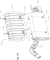
- FIG. 43 is an exploded view of an exhaust assembly of the powertrain assembly of FIG. 36 ;
- FIG. 44 is a front perspective view of an alternative embodiment of an operator cab of the vehicle of the present disclosure, including a roof assembly, a door assembly, and a front windshield;
- FIG. 45 is a rear perspective view of the operator cab of FIG. 44 , including a rear windshield;
- FIG. 46 is a front perspective of the operator cab of FIG. 44 ;
- FIG. 47 is a rear perspective view of the operator cab of FIG. 44 ;
- FIG. 48 is a front exploded view of the operator cab of FIG. 46 ;
- FIG. 49 is a side view of the door assembly of the operator cab of FIG. 44 ;
- FIG. 50 is a detailed perspective view of the door assembly of FIG. 49 ;
- FIG. 51 is a detailed perspective view of the door assembly of FIG. 49 , including a sealing member;
- FIG. 52 is an inner rear perspective view of the sealing member of FIG. 51 ;
- FIG. 53 is an exploded view of the sealing member of FIG. 52 ;
- FIG. 54 is a side view of a portion of the operator cab of FIG. 44 ;
- FIG. 55 is a bottom front perspective view of the roof assembly of FIG. 44 ;
- FIG. 56 is a side cross-sectional view of the roof assembly of FIG. 55 ;
- FIG. 57 is a bottom exploded view of the roof assembly of FIG. 55 ;
- FIG. 58 is an exploded view of a portion of the roof assembly of FIG. 55 .
- a utility vehicle 2 generally includes a frame assembly 50 supported by a plurality of ground engaging members, for example front wheels 4 and rear wheels 6 .
- the wheel base of illustrative vehicle 2 may be approximately 110-115 inches. In one embodiment, the wheel base of vehicle 2 is approximately 113 inches.
- Front and rear wheels 4 , 6 each may include a dual piston brake caliper, as is described further in U.S. patent application Ser. No. 11/494,891, filed on Jul. 28, 2006, and issued as U.S. Pat. No. 7,819,220 on Oct. 26, 2010, the complete disclosures of which are expressly incorporated by reference herein.
- Utility vehicle 2 includes a front end 8 having a hood 10 and body panels 12 .
- a rear end 14 of utility vehicle 2 includes a utility cargo box 16 .
- An integrated operator cab 20 is supported on frame assembly 50 between front end 8 and rear end 14 and illustratively encloses an operator area 22 .
- An upper frame assembly illustratively a roll cage assembly 260 , surrounds operator cab 20 .
- roll cage assembly 260 may support a front windshield 24 , a door assembly 560 , a roof assembly 610 , and a rear windshield 26 , all of which may be removably coupled from roll cage assembly 260 , as further detailed herein.
- Operator area 22 comprises a seating assembly 200 having at least a front seating section 202 and a rear seating section 220 (shown best in FIG. 25 ).
- Operator controls such as a steering assembly 430 and throttle controls 460 , are supported within cab 20 .
- the operator controls may be positioned on and within a dashboard 28 of operator cab 20 .
- the operator controls are configured to monitor, operate, and control the various systems of utility vehicle 2 , such as a powertrain assembly 470 ( FIG. 36 ) and an electrical system.
- operator controls may include controls for an HVAC assembly.
- vehicle 2 includes at least a heating assembly.
- Other operator controls may be configured to control accessories such as a winch and certain operator controls may include a wireless remote.
- frame assembly 50 supports a front suspension assembly 30 , shown in FIG. 1 , which includes an upper alignment arm 32 , a lower alignment arm 34 , and a shock absorber 36 .
- Shock absorber 36 may include spring coils and/or may be hydraulically operated.
- Frame assembly 50 further supports a rear suspension assembly 40 , which includes an upper alignment arm 42 , a lower alignment arm 44 , and a shock absorber 46 , as shown in FIG. 2 . Additional details of front suspension assembly 30 and rear suspension assembly 40 are included in U.S. patent application Ser. No. 11/494,891, filed on Jul. 28, 2006, and issued as U.S. Pat. No. 7,819,220 on Oct. 26, 2010; U.S.
- frame assembly 50 generally includes a front frame portion 51 , a mid-frame portion 52 , and a rear frame portion 54 .
- Frame assembly 50 extends along a longitudinal axis L ( FIG. 5 ) between front frame portion 51 and rear frame portion 54 .
- a plurality of lower longitudinal frame tubes 60 extend generally lengthwise between front frame portion 51 and rear frame portion 54 .
- lower longitudinal frame tubes 60 each include a front portion 60 a and a rear portion 60 b .
- Rear portion 60 b flares outwardly from front portion 60 a .
- a skid plate 130 may be coupled to front portion 60 a of lower longitudinal frame tubes 60 , as detailed further herein.
- Outer frame members 62 are positioned laterally outward from lower longitudinal frame tubes 60 . More particularly, a front portion 62 a of outer frame member 62 is adjacent to, and couples with, front portion 60 a , and a rear portion 62 b of outer frame member 62 is spaced apart from rear portion 60 b of lower longitudinal frame tube 60 . Rear portion 62 b is coupled to a longitudinal member 63 and a cross tube 64 extends between lower longitudinal frame tubes 60 and longitudinal member 63 .
- a frame channel 66 integrally couples each longitudinal frame tube 60 with the adjacent outer frame member 62 .
- couplers 140 join together various components of frame assembly 50 .
- couplers 140 join together front section 60 a and rear section 60 b of lower longitudinal frame tubes 60 .
- couplers 140 join together rear portion 62 b of frame members 62 and longitudinal member 63 .
- Couplers 140 include an outer member 142 and an inner member 144 .
- outer member 142 and inner member 144 may be the same component and arranged in an opposing orientation.
- outer member 142 may be received within front section 60 a of lower longitudinal frame tubes 60 and/or rear portion 62 b of outer frame members 62 and may be coupled thereto with conventional fasteners (e.g., welds, bolts, screws, rivets, adhesive).
- inner member 144 may be received within rear section 60 b of lower longitudinal frame tubes 60 and/or longitudinal members 63 and may be coupled thereto with welds, bolts, rivets, adhesive, or other conventional fasteners.
- outer member 142 and inner member 144 may be cast or otherwise formed with complementary surfaces, such that outer member 142 mates with inner member 144 when coupled together with fasteners 146 and 148 .
- Fasteners 146 are received through apertures 150 in outer member 142 and apertures 152 in inner member 144 to couple with fasteners 148 .
- Illustrative couplers 140 may be configured to couple with a plurality of frame tube sizes and/or frame tube profiles (e.g., square, circular).
- frame assembly 50 may include eight couplers 140 to connect various components and sections of frame assembly 50 . Additional details of couplers 140 may be found in U.S. patent application Ser. No. 12/796,495, filed on Jun. 8, 2010, which issued as U.S. Pat. No. 8,328,235 on Dec. 11, 2012, the complete disclosures of which are expressly incorporated by reference herein.
- a removable frame portion 70 is attached to each outer frame member 62 by way of a bracket 72 .
- Rear portion 62 b of outer frame member 62 is coupled to bracket 72 with fasteners 194 and 196 , as shown best in FIG. 12 , such that bracket 72 extends around rear portion 62 b .
- removable frame portion 70 has a lower frame portion 70 a and a vertically upstanding portion 70 b .
- Removable frame portion 70 further includes gussets 74 and conventional fasteners 71 coupled to upstanding portions 70 b and a front transverse brace 76 . Gussets 74 may support front windshield 24 , as further detailed herein.
- lower rails 68 are coupled to removable frame portions 70 . As shown in FIGS. 3 - 7 , lower rails 68 also are coupled to longitudinal member 63 with a bracket 75 and a support member 77 . Additional details of removable frame portion 70 and brackets 72 may be included in U.S. Provisional Patent Application Ser. No. 61/442,071, filed on Feb. 11, 2011; U.S. patent application Ser. No. 13/370,139, filed on Feb. 9, 2012; U.S. patent application Ser. No. 13/464,603, filed on May 4, 2012; and U.S. patent application Ser. No. 13/492,589, filed on Jun. 8, 2012, the complete disclosures of which are expressly incorporated by reference herein.
- frame assembly 50 may include nerf bars 160 .
- Nerf bars 160 may include a front section 162 and a rear section 164 .
- Front and rear sections 162 , 164 may be configured with a traction portion 166 to facilitate ingress into and egress from vehicle 2 .
- front section 162 is coupled to bracket 72 with a rounded tube 168 .
- Tube 168 is coupled to bracket 72 with a plate 172 and fasteners 170 and 174 .
- Plate 172 may be coupled to a forward-facing side of bracket 72 .
- Front and rear sections 162 , 164 may be coupled together with a tube 176 .
- tube 176 couples front and rear sections 162 , 164 to bracket 75 on longitudinal member 63 . More particularly, plates 180 of tube 176 couple with forward-facing and rearward-facing sides of bracket 75 and are secured thereto with fasteners 178 and 179 . Nerf bars 160 also are coupled to support posts 100 with a tube 182 and a plate 186 . Plate 186 and support posts 100 are configured to receive fasteners 184 and 188 .
- front transverse brace 76 further supports frame tubes 80 at front frame portion 51 .
- Frame tubes 80 extend in a forward direction from front transverse brace 76 and include a generally horizontal portion 80 a and a generally vertical portion 80 b .
- horizontal portion 80 a is coupled to front transverse brace 76 and generally vertical portion 80 b extends downwardly and may couple with lower longitudinal frame tubes 60 .
- Frame tubes 80 include gussets 82 for removably mounting various components of vehicle 2 (e.g., a brush guard, a front end attachment, and/or body panels).
- a front support plate 83 is mounted to frame tubes 80 and lower longitudinal frame tubes 60 .
- a cross-member 86 extends between frame tubes 80 and illustratively is positioned forward of front transverse brace 76 and rearward of front support plate 83 .
- a shear panel 88 having an opening 89 , couples with cross-member 86 and is angled rearwardly therefrom, as disclosed in U.S. Provisional Patent Application Ser. No. 61/442,071, filed on Feb. 11, 2011; U.S. patent application Ser. No. 13/370,139, filed on Feb. 9, 2012; U.S. patent application Ser. No. 13/464,603, filed on May 4, 2012; and U.S. patent application Ser. No.
- Opening 89 may allow wires, a plurality of cooling tubes 479 , hydraulic hoses, and other conduits to extend between various components of vehicle 2 .
- the lower portion of shear panel 88 couples with lower longitudinal frame tubes 60 and/or outer frame members 62 .
- shear panel 88 is coupled to longitudinal frame tubes 60 with gussets 84 , as shown in FIGS. 3 , 4 , 7 , and 10 .
- Gussets 84 may maintain bending stresses of vehicle 2 and provide increased strength and stiffness to frame assembly 50 .
- Shear panel 88 also is coupled to support plate 83 through a plurality of braces 87 ( FIGS. 3 - 5 and 10 ).
- front frame portion 51 includes a support member 190 for steering assembly 430 .
- Support member 190 is coupled to front transverse brace 76 and is further coupled to gusset 74 of removable frame portion 70 with fasteners 71 and 192 .
- mid-frame portion 52 of frame assembly 50 includes seating assembly 200 having front seating section 202 and rear seating section 220 .
- Front seating section 202 supports an operator seat 330 and a front passenger seat 336 within operator area 22 ( FIG. 25 ).
- Front seating section 202 includes transversely extending frame tubes 92 and 94 supported by upstanding braces 96 , 97 and diagonal braces 98 , 204 .
- Diagonal braces 98 and upstanding braces 96 are coupled to rear portions 62 b of outer frame members 62 .
- Upstanding braces 96 also may be coupled to a transverse frame member 212 via a plate 214 and fasteners 216 , 218 , and 219 , as shown best in FIG. 12 .
- Transverse frame member 212 includes plates 213 for coupling with other components of vehicle 2 , as detailed further herein.
- Upstanding brace 97 is coupled to diagonal brace 98 with a fastener 208 .
- Diagonal brace 204 extends between frame tube 92 and upstanding brace 97 .
- Frame tube 94 may be coupled to a transverse frame tube 206 with a fastener 210 .
- mid-frame portion 52 of frame assembly 50 further supports rear seating section 220 for a first rear passenger seat 342 , a second rear passenger seat 348 , and a third rear passenger seat 354 ( FIG. 25 ).
- Rear seating section 220 includes transversely extending frame tubes 222 , 224 supported by upstanding portions 226 . More particularly, frame tube 222 is coupled to an upstanding portion 226 via a diagonal brace 228 .
- Rear seating section 220 is coupled to longitudinal member 63 by a diagonal brace 230 .
- Upstanding portion 226 is coupled to diagonal brace 230 with a fastener 229 .
- diagonal brace 230 also supports a frame member 232 for coupling a frame member 234 to frame tube 224 with a fastener 235 .
- a brace 236 couples diagonal brace 230 to a support post 100 , which extends upwardly from longitudinal members 63 .
- Support posts 100 and braces 236 are coupled to a transverse beam 102 through mounting flanges 112 and 104 , respectively.
- mounting flange 104 includes a bracket 238 coupled to transverse beam 102 and is coupled to brace 236 with fasteners 242 , 244 .
- mounting flange 112 is coupled to transverse beam with a fastener 240 .
- Support posts 100 are coupled to diagonal braces 230 through braces 236 .
- transverse beam 102 may be removable from support posts 100 in order to assemble components of powertrain assembly 470 with frame assembly 50 .
- mid-frame portion 52 of frame assembly 50 further includes a skid plate 122 that extends between outer frame members 62 .
- Skid plate 122 couples with longitudinal members 63 and cross tube 64 .
- Skid plate 122 includes a plurality of apertures 128 ( FIG. 5 ), which reduce the weight of frame assembly 50 and allow heat from powertrain assembly 470 to dissipate from vehicle 2 .
- rear frame portion 54 includes an engine pan 106 positioned rearward of skid plate 122 and extending between lower longitudinal frame tubes 60 .
- Pan 106 defines a support platform for powertrain assembly 470 of vehicle 2 and is supported by a plurality of lower frame members 120 .
- pan 106 is integrally coupled with lower frame members 120 through a stamping process.
- pan 106 and lower frame members 120 may be separate components coupled together through conventional joining methods (bolts, welds, adhesive, rivets, etc.).
- Illustrative pan 106 includes a plurality of apertures 107 ( FIG. 5 ), which reduce the weight of frame assembly 50 and allow heat from powertrain assembly 470 to dissipate from vehicle 2 .
- a plurality of vertically-extending tubes 108 are coupled to pan 106 and a plurality of upper frame arms 110 .
- Upper frame arms 110 also are coupled to posts 100 through mounting flanges 112 .
- Rear frame portion 54 further includes a rear support plate 116 coupled to vertically-extending tubes 108 and lower frame members 120 .
- a tunnel member 132 is defined by skid plate 130 , a first harness 133 , a second harness 134 , a first bracket 135 , and a second bracket 136 .
- Tunnel member 132 is coupled to shear panel 88 and cross tubes 64 .
- Tunnel member 132 is supported on frame assembly 50 above lower longitudinal frame tubes 60 and, more particularly, is positioned above front portion 60 a of frame tubes 60 .
- tunnel member 132 extends between front frame portion 51 and rear frame portion 54 .
- first and second harnesses 133 and 134 may be comprised of a polymeric material and, illustratively, include retaining clips 137 for supporting cooling tubes 479 , hydraulic hoses, electrical wires, and/or other conduits. Additionally, first harness 133 supports a guide member 138 for locating and aligning cooling tubes 479 , hydraulic hoses, electrical wires, and/or other conduits at front frame portion 51 with retaining clips 137 .
- first harness 133 is coupled to gussets 84 with fasteners 256 .
- First harness 133 also may be supported on cross tube 66 with first bracket 135 .
- First bracket 135 is coupled to first harness 133 with fasteners 252 and cross tube 66 with fasteners 254 .
- First harness 133 is coupled to second harness 134 with fasteners 250 .
- first harness includes a flange 139 which receives second harness 134 and fasteners 250 .
- Second harness 134 is coupled to cross tube 64 with second bracket 136 .
- Second bracket 136 is coupled to cross tube 64 with fasteners 259 and is coupled to second harness 134 with fasteners 258 .
- cooling tubes 479 are fluidly coupled to powertrain assembly 470 and, for example, may be supported by tunnel member 132 in order to extend from a radiator at front frame portion 51 toward an engine 472 of powertrain assembly 470 in rear frame portion 54 .
- Cooling tubes 479 may be supported and aligned by guide member 138 and retaining clips 137 when extending toward rear frame portion 54 .
- Illustrative guide member 138 is angled downwardly such that cooling tubes 479 angle downwardly in order to couple with retaining clips 137 .
- Retaining clips 137 frictionally retain cooling tubes 479 such that cooling tubes 479 do not move along tunnel member 132 .
- retraining clips 137 generally surround approximately half of the outer diameter of cooling tubes 479 .
- ties or couplers may also retain cooling tubes 479 and other electrical wires and hydraulic hoses on tunnel member 132 .
- tunnel member 132 may support driveshaft 490 of powertrain assembly 470 .
- driveshaft 490 may be positioned between first and second harnesses 133 , 134 and skid plate 130 , and generally intermediate longitudinal frame tube 60 . Additional details of tunnel member 132 may be disclosed in U.S. Provisional Patent Application Ser. No. 61/442,071, filed on Feb. 11, 2011; U.S. Provisional Patent Application Ser. No. 61/696,519, filed on Sep. 4, 2012; U.S. patent application Ser. No. 13/1370,139, filed on Feb. 9, 2012; U.S. patent application Ser. No. 13/464,603, filed on May 4, 2012; and U.S. patent application Ser. No. 13/492,589, filed on Jun. 8, 2012, the complete disclosures of which are expressly incorporated by reference herein.
- roll cage assembly 260 generally surrounds operator cab 20 and operator area 22 .
- Roll cage assembly 260 may be removable from frame assembly 50 .
- Roll cage assembly 260 includes a front section 262 and a rear section 264 .
- Front section 262 includes upright portions 266 , horizontal portions 268 , an upper crossbeam 270 defining a surface 272 , and a lower crossbeam 274 defining a surface 276 .
- lower crossbeam 274 may support front windshield 24 ( FIG. 44 ) and is coupled to frame assembly 50 through gussets 74 and fasteners 278 .
- Lower crossbeam 274 may be comprised of a metallic or polymeric material and may be formed in metal stamping, injection molding, or other similar manufacturing methods. Additionally, lower crossbeam 274 is further coupled to a brace 280 with fasteners 282 . Brace 280 is supported on gusset 74 and also may support front windshield 24 . Lower crossbeam 274 also may be coupled to a bracket 284 with fasteners 286 . Illustratively, brackets 284 are coupled to removable frame portions 70 of frame assembly 50 . Brackets 284 may be formed by casting methods. As shown in FIG. 20 , lower crossbeam 274 is further coupled to front transverse brace 76 of frame assembly 50 with fasteners 288 . Front transverse brace 76 may support a support member 290 with fasteners 289 . Support member 290 may be operably coupled to front windshield 24 .
- Upright portions 266 of roll cage assembly 260 are coupled to brackets 284 and extend between brackets 284 and upper crossbeam 270 .
- lower ends 265 of upright portions 266 are profiled to compliment brackets 284 such that upright portions 266 are flush with brackets 284 and appear to form a continuous a frame member of roll cage assembly 260 .
- lower ends 265 are formed by casting methods and may be integrally or otherwise coupled to upright portions 266 .
- Upright portions 266 may include hand grips 292 for the operator and/or the front passenger.
- Upright portions 266 and horizontal portions 268 of front section 262 may be profiled in a generally hourglass or figure eight configuration, as detailed in U.S. Provisional Patent Application Ser. No.
- Rear section 264 of roll cage assembly 260 includes upright portions 294 , horizontal portions 296 , an upper crossbeam 298 , an intermediate crossbeam 300 , and a lower crossbeam 302 .
- Upright portions 294 are coupled to brackets 238 of frame assembly 50 and upper crossbeam 298 .
- upright portions 294 support bolster bars 308 , which may secure rear passengers in vehicle 2 .
- Horizontal portions 296 also are coupled to upper crossbeam 298 with fasteners 310 ( FIG. 23 ). As shown in FIGS.
- an outer end 299 of upright portions 294 may be a cast component and may be profiled to compliment a cast inner end 297 of horizontal portions 296 , such that horizontal portions 296 and upright portions 294 are generally flush when coupled together.
- Cast inner end 297 may be integrally formed with horizontal portions 296 through casting methods.
- Upright portions 294 and horizontal portions 296 of rear section 264 may be profiled in a generally hourglass or figure eight configuration, as detailed in U.S. Provisional Patent Application Ser. No. 61/442,071, filed on Feb. 11, 2011; U.S. patent application Ser. No. 13/1370,139, filed on Feb. 9, 2012; U.S. patent application Ser. No. 13/464,603, filed on May 4, 2012; and U.S. patent application Ser. No. 13/492,589, filed on Jun. 8, 2012, the complete disclosures of which are expressly incorporated by reference herein.
- upper crossbeam 298 , intermediate crossbeam 300 , and lower crossbeam 302 are coupled to upright portions 294 .
- diagonal members 304 are coupled to intermediate crossbeam 300 and extend outward to couple with upright portions 294 .
- Diagonal members 304 may include rear passenger headrests 312 .
- a panel 306 may be coupled to both intermediate crossbeam 300 and lower crossbeam 302 .
- Illustrative panel 306 may support portions of the electrical system of the vehicle, for example rear lights.
- Front section 262 and rear section 264 of roll cage assembly 260 may be coupled together with a transverse frame tube 314 .
- Transverse frame tube 314 extends between upright portions 316 .
- a first brace 318 and a second brace 320 extend between upright portions 316 .
- upright portions 316 also may support bolster bars 322 for securing a driver and a front passenger within vehicle 2 .
- upright portions 316 may include a bend 317 which angles the lower end of upright portions 316 rearwardly. As such, bend 317 may increase the ingress and egress space for the operator and a front passenger.
- transverse frame tube 314 and upright portions 316 are coupled to horizontal portions 268 , 296 at coupling locations 324 .
- Coupling locations 324 illustratively define a “T” member between horizontal portions 268 , 296 and upright portions 316 .
- locating pins 246 FIG. 24 may be received within locating recesses 248 .
- horizontal portions 268 include cast ends 267 having an inner surface 269 . Cast ends 267 may be integrally formed with horizontal portions 268 through casting methods.
- Horizontal portions 296 also include cast ends 291 having an outer surface 293 and an inner surface 295 . Cast ends 291 may be integrally formed with horizontal portions 296 through casting methods.
- Outer surface 293 of cast ends 291 of horizontal portions 296 may be profiled to compliment inner surface 269 of cast ends 267 of horizontal portions 268 , such that when horizontal portions 296 are coupled to horizontal portions 268 with fasteners 326 , horizontal portions 296 are generally flush with horizontal portions 268 .
- horizontal portions 268 of front section 262 form a continuous frame member with horizontal portions 296 of rear section 264 of roll cage assembly 260 .
- inner surface 295 of cast ends 291 of horizontal portions 296 may be profiled to compliment an outer surface 315 of a cast end 319 of upright portions 316 , such that when horizontal portions 296 are coupled to upright portions 316 with fasteners 328 , horizontal portions 296 are generally flush with upright portions 316 .
- Cast end 319 may be integrally formed with upright portions 316 through casting methods. In this way, the adjoining components of roll cage assembly 260 appear to form continuous sections.
- Operator seat 330 is defined by a seat bottom 332 and a seat back 334
- front passenger seat 336 is defined by a seat bottom 338 and a seat back 340
- Seat bottoms 332 , 338 may be pivotably coupled to front seating section 202 of frame assembly 50 , as detailed further herein.
- Operator seat 330 and front passenger seat 336 may include seat restraints, such as a three-point seat belt or a multi-point seat harness.
- a portion of the seat belts for front seating section 202 may be coupled to brackets 219 on transverse frame member 212 ( FIG. 11 ).
- Rear seating section 220 supports first rear passenger seat 342 defined by a seat bottom 344 and a seat back 346 , second rear passenger seat 348 defined by a seat bottom 350 and a seat back 352 , and third rear passenger seat 354 defined by a seat bottom 356 and a seat back 358 .
- Rear passenger seats 342 , 348 , and 354 are positioned above a rear floorboard 418 ( FIG. 29 ).
- first rear passenger seat 342 is positioned generally rearward of operator seat 330
- second rear passenger seat 348 is positioned generally rearward of center console 392
- third rear passenger seat 354 is positioned generally rearward of front passenger seat 336 .
- second rear passenger seat 348 is intermediate first and third rear passenger seats 342 and 354 , respectively.
- First, second, and third rear passenger seats 342 , 348 , and 354 may be coupled to frame tube 224 with a latch assembly comprising at least one pin and at least one polymeric bumper.
- Headrests 312 may be coupled to diagonal members 304 of rear section 264 of roll cage assembly 260 to provide support for passengers in first and/or third rear passenger seats 342 , 354 .
- seat bottoms 344 , 350 , and 356 of first, second, and third rear passenger seats 342 , 348 , and 354 , respectively, may be coupled together to form a bench seat.
- Seat bottoms 344 , 350 , and 356 also may be configured in a 60 / 40 arrangement such that seat bottoms 344 and 350 may comprise a majority of a bench seat, for example.
- seat bottoms 344 , 350 , and 356 may be separate seat bottoms.
- seat backs 346 , 352 , and 358 may be coupled together to form a single back rest for rear passengers.
- seat backs 346 , 352 , and 358 may be separate seat backs.
- Shoulder members 343 a , 349 a , and 355 a are configured to couple with locking members 343 b , 349 b , and 355 b , respectively.
- Locking members 343 b , 349 b , and 355 b are adjacent seat bottoms 344 , 350 , and 356 , respectively, and may be coupled to brackets 103 on transverse beam 102 ( FIG. 13 ).
- each seat restraint 343 , 349 , and 355 is a three-point harness seat belt.
- operator area 22 of operator cab 20 may include a plurality of accessories.
- a plurality of storage containers 360 , 406 , and 408 may be positioned below seats 330 , 336 , 342 , 348 , and 354 , as detailed further herein. More particularly, front storage containers 360 may be positioned below operator seat 330 and front passenger seat 336 . Similarly, rear storage containers 406 may be positioned below first and third rear passenger seats 342 and 354 , respectively. Additionally, rear storage container 408 may be positioned below second rear passenger seat 348 .
- illustrative storage containers 360 , 406 , and 408 are “dry” storage containers for sealing the cargo and other components therein from water, dirt, and debris.
- first seating section 202 includes hinges 362 on frame tube 92 .
- Hinges 362 are operably coupled to seat bottoms 332 and 338 of operator seat 330 and front passenger seat 336 , respectively.
- seat bottoms 332 , 338 are configured to pivot in a forward direction about hinges 362 in order to expose storage containers 360 .
- storage containers 360 include a front wall 364 , a rear wall 366 , an outer side wall 368 , an inner side wall 370 , and a bottom surface 372 which generally enclose an interior space 374 of storage container 360 . Cargo and other items may be retained within interior space 374 of storage containers 360 and may be easily accessed by pivoting operator seat 330 and/or front passenger seat 336 to the open position about hinges 362 .
- storage containers 360 may include an electrical outlet operably coupled to the electrical system of vehicle 2 for charging or powering user accessories, such as phones, GPS devices, and/or computers.
- front floorboard 420 ( FIG. 1 ) also may include at least one electrical outlet for auxiliary power.
- Bottom surface 372 of storage container 360 may include a drain opening 376 which allows any fluids, dirt, or debris within interior space 374 to fall through. As such, drain opening 376 prevents dirt and fluids from accumulating in storage container 360 .
- a plug or other sealing member may cover drain opening 376 in order to prevent dirt and debris below vehicle 2 from entering storage container 360 through drain opening 376 .
- a top surface 378 of storage containers 360 includes an outer rim 380 and an inner lip 382 that define a channel 384 therebetween.
- channel 384 may include a plurality of drain openings 386 . As such, any fluid, dirt, or debris within channel 384 may fall through drain openings 386 and out of vehicle 2 . Plugs or other sealing members (not shown) may cover drain openings 386 during operation of vehicle 2 .
- seat bottoms 332 , 338 may be used to close interior space 374 of storage container 360 .
- illustrative storage containers 360 may include lids 388 , as shown in FIG. 29 .
- Lid 388 is positioned over interior space 374 and may be retained on lip 382 of top surface 378 with an outer latch 390 .
- lid 388 is configured to “snap” onto storage container 360 because outer latch 390 “hooks” or couples around lip 382 . As such, lid 388 is easy to assemble with storage containers 360 to seal interior space 374 , and is easily removed from storage container 360 without the use of tools.
- operator area 22 of cab 20 also includes a storage container 400 within center console 392 .
- Center console 392 may be supported by a frame bracket welded or riveted to frame tubes 92 , 94 of front seating section 202 in order to prevent center console 392 from being removed from vehicle 2 .
- center console 392 is removable from vehicle 2 .
- Center console 392 is intermediate operator seat 330 and front passenger seat 336 and may include a lid 394 , a base 396 , hinges 398 , and accessories, for example front cup holders 402 .
- Lid 394 is coupled to base 396 through hinges 398 and pivots about hinges 398 in a generally rearward direction.
- hinges 398 may be molded into lid 394 and base 396 such that hinges 398 are integral with lid 394 and base 396 . As such, hinges 398 on lid 394 snap or clip into hinges 398 on base 396 such that no additional hardware or coupling components are required. Alternatively, hinges 398 may be coupled to lid 394 and base 396 with conventional fasteners.
- Storage container 400 may be a “dry” container because a seal 395 is supported on lid 394 and/or base 396 .
- Storage container 400 may be configured to support cargo for the operator and/or passengers, or may be configured to support components of vehicle 2 .
- storage container 400 may include an electrical outlet operably coupled to the electrical system of vehicle 2 for charging or powering accessories, such as phones, GPS devices, and/or computers.
- Storage container 400 may include a drain opening (not shown) similar to drain opening 376 of storage containers 360 .
- rear seating section 220 includes hinges 404 on frame tube 222 .
- Hinges 404 are operably coupled to seat bottoms 344 , 350 , and 356 of first, second, and third rear passenger seats 342 , 348 , and 354 , respectively.
- seat bottoms 344 , 350 , and 356 are configured to pivot in a forward direction about hinges 404 in order to expose storage containers 406 and 408 .
- Cargo and other items may be retained within storage containers 406 , 408 and may be easily accessed by pivoting seat bottoms 344 , 350 , and 356 to the open position about hinges 404 .
- components of vehicle 2 such as components of the electrical system may be supported within storage containers 406 and 408 .
- controls and fuses for the electrical system may be supported in storage container 408 under seat bottom 350 so as to be closer to powertrain assembly 470 . In this way, the electrical connections from the controls and the fuses may be shorter due to the proximity to powertrain assembly 470 . Additionally, a user may easily access any controls and/or fuses in storage container 408 for replacement or repair.
- seat bottoms 344 , 350 , and 356 are coupled together to form a single bench seat such that seat bottoms 344 , 350 , and 356 pivot simultaneously about hinges 404 to expose storage containers 406 and storage container 408 .
- storage containers 406 and 408 include an electrical outlet operably coupled to the electrical system of vehicle 2 for charging or powering user accessories, such as phones, GPS devices, and/or computers. Additional auxiliary power outlets may be coupled to rear floorboards 418 .
- Rear storage containers 406 and 408 may have less cargo space than front storage containers 360 because other components of vehicle 2 , for example a fuel tank 500 and a battery may be supported by frame assembly 50 under rear passenger seats 342 , 348 , and 354 .
- storage containers 406 and 408 may be closed when seat bottoms 344 , 350 , and 356 are latched against frame tube 224 .
- storage containers 406 and 408 also may include lids (not shown). The lids may be easily assembles with and removed from storage containers 406 and 408 without the use of tools.
- rear seating section 202 of frame assembly 50 also may support additional accessories, for example rear cup holders 410 .
- Rear cup holders 410 and/or other accessories may be coupled to a body panel wall 412 separating front seating section 202 from rear seating section 220 .
- Body panel wall 412 is coupled to rear floorboard 418 and illustratively is angled downwardly in a forward direction. With this angled configuration, body panel wall 412 extends partially under operator seat 330 and front passenger seat 336 to increase a foot space 414 for rear passengers.
- a lower portion 416 of rear wall 366 of front storage containers 360 is recessed.
- the profile and angle of lower portion 416 generally corresponds to the profile and angle of body panel wall 412 to maximize foot space 414 for the rear passengers.
- body panel wall 412 may includes a toe panel 422 .
- Rear passengers may position their toes against toe panel 422 and, as such, the foot space 414 and leg room for the rear passengers is increased.
- the feet of the rear passengers may partially extend to a position forward of transverse frame member 212 and seat backs 334 and 340 of front seating section 202 such that the feet of the rear passengers are partially under a portion of front storage containers 360 .
- operator area 22 of operator cab 20 also includes steering assembly 430 and throttle controls 460 .
- Steering assembly 430 includes a steering wheel 432 , a steering post 434 , a steering shaft 436 , a joint member 438 , a housing 440 , a bracket 442 , and an adjustment member 452 .
- Steering wheel 432 is coupled to steering post 434 and steering shaft 436 in order to transmit the motion of steering wheel 432 to front wheels 4 .
- Steering shaft 436 is coupled to joint member 438 for coupling with additional components of steering assembly 430 .
- Housing 440 extends generally around joint member 438 and a portion of steering post 434 and steering shaft 436 .
- Housing 440 may be coupled to brackets 442 with a mounting assembly which includes a fastener 444 , a washer 446 , a bearing 448 , a bushing 450 , and a coupler 451 .
- bushing 450 may be a plastic “snap-in” component.
- bushing 450 may be a rivet-style component.
- fasteners 444 are received through apertures in bracket 442 and housing 440 and are coupled thereto with couplers 451 .
- couplers 451 are adjacent an inner surface of housing 440 .
- Washer 446 and bearing 448 may be positioned intermediate fastener 444 and coupler 451 .
- Bushing 450 may be positioned over fastener 444 , washer 446 , and bearing 448 .
- Steering assembly 430 also may include adjustment member 452 which adjusts the height and tilt position of steering wheel 432 .
- adjustment member 452 is a hydraulic shock that raises and lowers steering wheel 432 when the operator depresses a lever 458 .
- adjustment member 452 may be other devices configured to adjust the position of steering wheel 432 .
- Lever 458 is operably coupled to adjustment member 452 .
- housing 440 is configured to move with steering wheel 432 .
- Adjustment member 452 is coupled to a lever arm 454 with fasteners 456 .
- adjustment member is coupled to steering post 434 with a bracket 455 and fasteners 456 .
- throttle controls 460 include an electronic throttle control (“ETC”) assembly 462 surrounded by a housing 464 and operably coupled to an accelerator pedal 466 , as is described in U.S. patent application Ser. No. 13/464,603, filed on May 4, 2012, and U.S. patent application Ser. No. 13/492,589, filed on Jun. 8, 2012, the complete disclosures of which are expressly incorporated by reference herein.
- a lever arm 465 is operably coupled to accelerator pedal 466 .
- Accelerator pedal 466 is adjacent a brake pedal 468 .
- Powertrain assembly 470 includes an engine 472 , a transmission 474 , an air intake assembly 476 , and an exhaust assembly 478 .
- Powertrain assembly 470 also is coupled to fuel tank 500 ( FIG. 39 ) for supplying fuel to engine 472 .
- powertrain assembly 470 is coupled to a cooling assembly having cooling tubes 479 ( FIG. 18 ) extending from a radiator at front end 8 of vehicle 2 .
- Powertrain assembly 470 may be configured to output approximately 60 hp and vehicle 2 may reach speeds of up to approximately 50 mph.
- Illustrative engine 472 may be configured to operate with diesel fuel or gasoline from fuel tank 500 and is operably coupled to transmission 474 .
- Illustrative transmission 474 may be a continuously variable transmission (“CVT”). Additional details of engine 472 and transmission 474 are disclosed in U.S. Provisional Patent Application Ser. No. 61/385,802, filed on Sep. 23, 2010; U.S. patent application Ser. No. 13/242,229, filed on Sep. 23, 2011; and U.S. patent application Ser. No. 13/242,239, filed on Sep. 23, 2011, the complete disclosures of which are expressly incorporated by reference herein.
- CVT continuously variable transmission
- powertrain assembly 470 further includes a rear differential assembly 480 .
- Rear differential assembly 480 is enclosed within a casing 482 supported on rear frame portion 54 and includes an input shaft 484 and an output shaft 486 .
- Input shaft 484 is operably coupled to transmission 474 and output shaft 486 is operably coupled to driveshaft 490 in order to drive front wheels 4 of vehicle 2 .
- Rear differential assembly 480 also includes a splined bearing 488 for coupling with the half shafts of rear wheels 6 in order to drive rear wheels 6 .
- driveshaft 490 includes a front portion 490 a and a rear portion 490 b .
- Front portion 490 a is operably coupled to rear portion 490 b with a joint 491 , illustratively, a U-joint.
- a joint 491 illustratively, a U-joint.
- Rear portion 490 b is supported on longitudinal frame tubes 60 with a bearing 492 .
- bearing 492 is a hanger bearing.
- Bearing 492 is coupled to brackets 494 (also shown in FIG. 9 ) with fasteners 496 and 498 .
- Rear portion 490 b is rotatably coupled to output shaft 486 of rear differential assembly 480 .
- front portion 490 a is rotatably coupled to a front differential assembly.
- powertrain assembly 470 is operably coupled to fuel tank 500 .
- fuel flows from fuel tank 500 to engine 472 through a fuel line 502 .
- a vent tube 504 of fuel tank 500 extends towards an outer side of vehicle 2 and exhausts gases therein from the side operator side of vehicle 2 .
- Vent tube 504 may be coupled to frame member 234 with ties or other fasteners.
- Fuel may be added to fuel tank 500 through a fuel inlet when a cap 506 is removed ( FIG. 1 ). Cap 506 is supported on a side body panel 508 . Additional details of fuel tank 500 may be disclosed in U.S. Provisional Patent Application Ser. No. 61/442,071, filed on Feb. 11, 2011; U.S. patent application Ser. No.
- Air intake assembly 476 includes an air intake assembly 510 for transmission 474 and an air intake assembly 520 for engine 472 .
- Transmission air intake assembly 510 includes an inlet 512 supported on a side body panel 514 ( FIG. 2 ). As shown in FIG. 36 , air from inlet 512 on the passenger side of vehicle 2 flows inwardly and into transmission 474 . Air is exhausted from an exhaust port 516 and flows outwardly toward the passenger side of vehicle 2 , for example across exhaust assembly 478 . Additional details of transmission air intake assembly 510 are disclosed in U.S. Provisional Patent Application Ser. No. 61/442,071, filed on Feb. 11, 2011; U.S. patent application Ser. No. 13/1370,139, filed on Feb. 9, 2012; U.S. patent application Ser. No. 13/464,603, filed on May 4, 2012; and U.S. patent application Ser. No. 13/492,589, filed on Jun. 8, 2012, the complete disclosures of which are expressly incorporated by reference herein.
- engine air intake assembly 520 includes an inlet 522 supported on a side body panel 524 ( FIG. 1 ) on the operator side of vehicle 2 .
- inlet 522 is positioned above cap 506 of fuel tank 500 .
- Inlet 522 is coupled to a hose 526 with conventional fasteners, illustratively a clamp.
- hose 526 is coupled to a hose 528 with a clamp.
- Hose 528 includes a one-way port or valve, illustratively a duckbill port 530 , which allows water within hose 528 to flow outwardly therefrom but does not allow air or particulate matter (e.g., dirt, debris) flow into hose 528 .
- Hose 528 is coupled to an air box assembly 532 , which includes a lid 534 and a base 536 .
- Lid 534 is coupled to base 536 with latches 538 .
- Base 536 may include a drain opening.
- Air box assembly 532 further includes a filter supported between lid 534 and base 536 . Air flows from air box assembly 532 , through a hose 540 , and into an air plenum assembly 542 .
- air plenum assembly 542 includes a top portion 544 and a bottom portion 546 .
- Top portion 544 and bottom portion 546 may be comprised of a metallic or polymeric material and may be formed through casting or injection molding methods.
- Top portion 544 may be coupled to bottom portion 546 through heat or sonic welding.
- top portion 544 may be coupled to bottom portion 546 with conventional fasteners.
- a filter may be included within air plenum assembly 542 .
- Air plenum assembly 542 includes an inlet port 548 for receiving air from air box assembly 532 through hose 540 .
- air plenum assembly 542 includes at least one output port 549 .
- air plenum assembly 542 includes two output ports 549 .
- Output ports 549 are coupled to engine 472 in order to provide air thereto for combustion. As shown in FIG. 42 , inlet port 548 and output ports 549 are supported on top portion 544 of air plenum assembly 542 . Additional details of engine air intake assembly 520 are disclosed in U.S. Provisional Patent Application Ser. No. 61/442,071, filed on Feb. 11, 2011; U.S. patent application Ser. No. 13/1370,139, filed on Feb. 9, 2012; U.S. patent application Ser. No. 13/464,603, filed on May 4, 2012; and U.S. patent application Ser. No. 13/492,589, filed on Jun. 8, 2012, the complete disclosures of which are expressly incorporated by reference herein.
- Exhaust assembly 478 also is fluidly coupled to engine 472 in order to exhaust gases therefrom.
- exhaust assembly 478 includes an inlet hose 550 , a muffler 552 , an exhaust pipe 554 , and a heat shield 556 .
- Inlet hose 550 is coupled to a portion of engine 472 in order to exhaust gases therefrom. Gases from engine 472 flow through inlet hose 550 and into muffler 552 . Gases from muffler 552 flow out of vehicle 2 through exhaust pipe 554 .
- Heat shield 556 is coupled to muffler 552 with fasteners 557 and 558 . More particularly, as shown in FIG.
- operator cab 20 may be enclosed with roof assembly 610 , door assembly 560 , front windshield 24 , and rear windshield 26 . Additional details of front windshield 24 and rear windshield 26 , including the details of mounting windshields 24 , 26 to frame assembly 50 , are disclosed in U.S. Provisional Patent Application Ser. No. 61/442,071, filed on Feb. 11, 2011; U.S. patent application Ser. No. 13/1370,139, filed on Feb. 9, 2012; U.S. patent application Ser. No. 13/464,603, filed on May 4, 2012; and U.S. patent application Ser. No. 13/492,589, filed on Jun. 8, 2012, the complete disclosures of which are expressly incorporated by reference herein.
- door assembly 560 includes front doors 562 and rear doors 564 .
- Doors 562 , 564 are removably hinged at upright portions 316 , 294 , respectively, such that doors 562 , 564 swing rearwardly when opening.
- Doors 562 , 564 include windows 569 and latches 568 .
- Latches 568 are released when opening doors 562 , 564 and are engaged when doors 562 , 564 are closed against roll cage assembly 260 . Additional details of windows 569 and latches 568 are disclosed in U.S. patent application Ser. No. 13/1370,139, filed on Feb. 9, 2012; U.S. patent application Ser. No. 13/464,603, filed on May 4, 2012; and U.S.
- doors 562 , 564 may be generally flush with roll cage assembly 260 when closed. Doors 562 , 564 also include sealing members 566 which are compressed against doors 562 , 564 and roll cage assembly 260 to seal and isolate operator cab 20 and operator area 22 .
- upright portions 294 , 316 of roll cage assembly 260 may support a hinge member 570 .
- Hinge member 570 is configured to receive a hinge pin 574 .
- Hinge pin 574 for front doors 562 is supported on plates 213 of transverse frame member 212 with fasteners 576 .
- hinge pin 574 for rear doors 564 is supported on bracket 238 with fasteners 576 .
- Hinge pin 574 is received within hinge member 570 and rotates therein when doors 562 , 564 are opened and closed.
- doors 562 , 564 may be easily removed from roll cage assembly 260 by lifting up on doors 562 , 564 .
- Each door 562 , 564 also may include an auxiliary latching assembly for limiting the movement of doors 562 , 564 when open.
- the auxiliary latching assembly may be a strap with a buckle. Additional details of doors 562 , 564 , hinge members 570 , hinge pins 574 , and the auxiliary latching assembly are disclosed in U.S. patent application Ser. No. 13/1370,139, filed on Feb. 9, 2012; U.S. patent application Ser. No. 13/464,603, filed on May 4, 2012; and U.S. patent application Ser. No. 13/492,589, filed on Jun. 8, 2012, the complete disclosures of which are expressly incorporated by reference herein.
- front doors 562 may include an inner cover member or skin 578 which substantially covers the inner side of front doors 562 .
- illustrative rear doors 564 may include an inner cover member or skin 579 which partially covers the inner side of rear doors 564 .
- inner cover member 579 of rear doors 564 covers the portions of doors 564 that the rear passengers are likely to contact.
- inner cover member 579 is positioned in a middle section of rear doors 564 to protect the rear passengers' hands and arms.
- seals 566 may be compressed between doors 562 , 564 and roll cage assembly 260 to seal operator cab 20 . Additionally, rear doors 564 may be further sealed against roll cage assembly 260 , and in particular, upright portions 316 , with a sealing assembly 580 .
- Exemplary sealing assembly 580 is comprised of an injection molded polymeric material. Sealing assembly 580 is coupled to upright portions 316 and also is coupled to body panels 588 , 589 coupled to upright portions 316 ( FIGS. 44 and 45 ). Sealing assembly 580 includes an upper portion 582 and a lower portion 584 . Upper portion 582 and lower portion 584 are coupled together at a protrusion 590 . Protrusion 590 is positioned adjacent a post 571 of door latches 568 .
- Upper portion 582 includes a top end member 586 which may be integrally formed with upper portion 582 or may be coupled thereto with conventional fasteners (e.g., welds, rivets, adhesive, bolts, screws, or staples).
- top end member 586 is rounded and contacts both upright portions 316 and horizontal portions 294 .
- Upper portion 582 is coupled to an inner profiled surface 600 of upright portions 316 with fasteners 592 .
- Fasteners 592 extend through apertures 594 of sealing assembly 580 and through apertures 598 of profiled inner surface 600 of upright portions 316 .
- Lower portion 584 is coupled to a side surface 602 of body panel 588 and a side surface 604 of body panel 589 .
- fasteners 592 extend through apertures 594 of lower portion 584 and apertures 596 of body panels 588 , 589 .
- Fasteners 592 also may couple body panels 588 , 589 to portions of frame assembly 50 , such that fasteners 592 perform the function of both coupling sealing assembly 580 to vehicle 2 and coupling body panels 588 , 589 to frame assembly 50 .
- lower portion 584 may extend rearwardly from side surfaces 602 , 604 , of body panels 588 , 589 , respectively.
- FIG. 54 when closed, rear doors 564 are flush with sealing assembly 580 such that rear doors 564 are sealed against body panels 588 , 589 and upright portions 316 .
- sealing member 566 may further seal rear doors 564 against horizontal portions 296 and upright portions 294 of roll cage assembly 260 .
- roof assembly 610 includes a first outer member 612 , a second outer member 614 , a first inner member 616 , and a second inner member 620 .
- First outer member 612 includes coupling members, illustratively hooks 632 , for coupling with upper crossbeam 270 of roll cage assembly 260 . Hooks 632 extend into openings 271 ( FIG. 21 ) of upper crossbeam 270 in order to retain first outer member 612 to upper crossbeam 270 .
- a seal 636 may be positioned intermediate first outer member 612 and upper crossbeam 270 . Seal 636 is compressed therebetween in order to isolate operator cab 20 .
- Outer member 612 also includes a plurality of bosses 634 . Bosses 634 may be internally threaded to receive fasteners, as detailed further herein. As shown, first outer member 612 is generally positioned above front section 262 of roll cage assembly 260 and first seating section 202 of frame assembly 50 .
- Second outer member 614 includes a plurality of coupling members, illustratively front hooks 640 and rear hooks 642 .
- Front hooks 640 extend around a forward side of transverse frame tube 314 of roll cage assembly 260 and include a tab 641 which receives a fastener, as detailed further herein.
- Rear hooks 642 extend into openings 287 of upper rear crossbeam 298 of roll cage assembly 260 . In this way, second outer member 614 is retained on roll cage assembly 260 .
- a seal 664 may be positioned intermediate second outer member 614 and rear upper crossbeam 298 to isolate operator cab 20 .
- Second outer member 614 may also include a plurality of bosses 644 , which may be internally threaded to receive fasteners, as detailed further herein. As shown, second outer member 614 is generally positioned above rear section 264 of roll cage assembly 260 and second seating section 220 of frame assembly 50 .
- First and second outer members 612 , 614 are coupled together and illustratively overlap each other at a middle portion 646 .
- Middle portion 646 defines the apex of roof assembly 610 such that first outer member 612 and second outer member 614 taper downwardly from middle portion 646 .
- middle portion 646 prevents water or debris from puddling on roof assembly 610 .
- a seal 648 may be positioned intermediate first and second outer members 612 , 614 in order to seal roof assembly 610 at middle portion 646 .
- First inner member 616 is positioned below first outer member 612 and includes accessory portions 618 for supporting speakers, lights, or other components of vehicle 2 . Additionally, first inner member 616 includes a plate 650 and a plurality of slots 652 for coupling with second inner member 620 , as further detailed herein. First inner member 616 is configured to receive fasteners 630 for coupling first inner member 616 to first outer member 612 . More particularly, as shown in FIG. 56 , fasteners 630 are received within bosses 634 of first outer member 612 and are tightened to minimize the vertical gap and prevent sagging between first inner member 616 and first outer member 612 . Seals 654 ( FIG. 57 ) may be positioned intermediate first outer member 612 and first inner member 616 in order to seal roof assembly 610 .
- Second inner member 620 is positioned rearward of first inner member 616 and below second outer member 614 .
- Second inner member 620 includes accessory portions 622 for supporting speakers, lights, or other components of vehicle 2 .
- second inner member 620 includes a protrusion 656 having a plurality of fingers 658 and an opening 660 .
- Protrusion 656 is “V” shaped and is configured to receive transverse frame tube 314 .
- Second inner member 620 is configured to receive fasteners 626 for coupling second inner member 620 to second outer member 614 . More particularly, as shown in FIG. 56 , fasteners 626 are received within bosses 644 of second outer member 614 and are tightened to minimize the vertical gap and prevent sagging between second inner member 620 and second outer member 614 .
- Seals 662 ( FIG. 57 ) may be positioned intermediate second outer member 614 and second inner member 620 in order to seal roof assembly 610 .
- Second inner member 620 may be coupled to first inner member 616 through protrusion 656 . More particularly, plate 650 of first inner member 616 is received within protrusion 656 of second inner member 620 , as shown best in FIG. 56 . Fingers 658 of protrusion 656 extend upwardly along plate 650 and are received within slots 652 of first inner member 616 . As such, first inner member 616 is retained on second inner member 620 without requiring tools. Additionally, a fastener 628 may be received through protrusion 656 of second inner member 620 and tab 641 of front hooks 640 of second outer member 614 . As such, fastener 628 and tab 641 couple together second outer member 614 and second inner member 620 .
- first and second outer members 612 , 614 may be positioned on roll cage assembly 260 and moved into proper position and alignment by pulling rearwardly on roof assembly 610 .
- hooks 632 of first outer member 612 couple with openings 271 of front upper crossbeam 270 and first outer member 612 slides rearwardly into second outer member 614 at middle portion 646 .
- Front hooks 640 of second outer member 614 also slide rearwardly to extend around a portion of transverse frame tube 314 .
- rear hooks 642 of second outer member 614 extend into openings 287 of rear upper crossbeam 298 . In this way, first and second outer members 612 , 614 are retained together on roll cage assembly 260 in a tool-less manner (i.e., without requiring tools).
- First and second inner members 616 , 620 are assembled after first and second outer members 612 , 614 have been coupled to roll cage assembly 260 .
- Seals 636 , 648 , 654 , 662 , and 664 may be positioned around the perimeter of roof assembly 610 and compressed between first outer member 612 , first inner member 616 , second outer member 614 , and second inner member 620 .
- First inner member 616 may be coupled to first outer member 612 through fasteners 630 and bosses 634 .
- Second inner member 620 may then be coupled to first inner member 616 by positioning fingers 658 of protrusion 656 in slots 652 of first inner member 616 .
- protrusion 656 may receive fastener 628 through tab 641 of front hooks 640 in order to secure second inner member 620 to second outer member 616 .
- Second inner member 620 also may be coupled to second outer member 614 with fasteners 626 .
- Fasteners 626 may be received within bosses 644 of second outer member 614 and tightened to secure second inner member 620 to second outer member 614 .
- fasteners 624 may be received through second inner member 620 in order to further couple second inner member 620 to second outer member 614 .
- assembling roof assembly 610 with roll cage assembly 260 may be a tool-less operation (i.e., no tools are required for assembling roof assembly 610 with roll cage assembly 260 ). Tools also are not required for coupling together first outer member 612 , second outer member 614 , first inner member 616 , and second inner member 620 .
Landscapes
- Engineering & Computer Science (AREA)
- Mechanical Engineering (AREA)
- Transportation (AREA)
- Aviation & Aerospace Engineering (AREA)
- Chemical & Material Sciences (AREA)
- Combustion & Propulsion (AREA)
- Body Structure For Vehicles (AREA)
- Tents Or Canopies (AREA)
- Vehicle Waterproofing, Decoration, And Sanitation Devices (AREA)
- Fittings On The Vehicle Exterior For Carrying Loads, And Devices For Holding Or Mounting Articles (AREA)
- Seats For Vehicles (AREA)
Abstract
Description
Claims (23)
Priority Applications (2)
| Application Number | Priority Date | Filing Date | Title |
|---|---|---|---|
| US17/323,742 US12017702B2 (en) | 2013-03-15 | 2021-05-18 | Utility vehicle |
| US18/663,376 US12686442B2 (en) | 2013-03-15 | 2024-05-14 | Utility vehicle |
Applications Claiming Priority (4)
| Application Number | Priority Date | Filing Date | Title |
|---|---|---|---|
| US201361788874P | 2013-03-15 | 2013-03-15 | |
| US14/212,092 US9789909B2 (en) | 2013-03-15 | 2014-03-14 | Utility vehicle |
| US15/722,535 US11066105B2 (en) | 2013-03-15 | 2017-10-02 | Utility vehicle |
| US17/323,742 US12017702B2 (en) | 2013-03-15 | 2021-05-18 | Utility vehicle |
Related Parent Applications (1)
| Application Number | Title | Priority Date | Filing Date |
|---|---|---|---|
| US15/722,535 Continuation US11066105B2 (en) | 2013-03-15 | 2017-10-02 | Utility vehicle |
Related Child Applications (1)
| Application Number | Title | Priority Date | Filing Date |
|---|---|---|---|
| US18/663,376 Continuation US12686442B2 (en) | 2013-03-15 | 2024-05-14 | Utility vehicle |
Publications (2)
| Publication Number | Publication Date |
|---|---|
| US20210269096A1 US20210269096A1 (en) | 2021-09-02 |
| US12017702B2 true US12017702B2 (en) | 2024-06-25 |
Family
ID=50829243
Family Applications (4)
| Application Number | Title | Priority Date | Filing Date |
|---|---|---|---|
| US14/212,092 Active 2035-05-29 US9789909B2 (en) | 2013-03-15 | 2014-03-14 | Utility vehicle |
| US15/722,535 Active 2035-05-16 US11066105B2 (en) | 2013-03-15 | 2017-10-02 | Utility vehicle |
| US17/323,742 Active 2034-06-13 US12017702B2 (en) | 2013-03-15 | 2021-05-18 | Utility vehicle |
| US18/663,376 Active 2034-09-12 US12686442B2 (en) | 2013-03-15 | 2024-05-14 | Utility vehicle |
Family Applications Before (2)
| Application Number | Title | Priority Date | Filing Date |
|---|---|---|---|
| US14/212,092 Active 2035-05-29 US9789909B2 (en) | 2013-03-15 | 2014-03-14 | Utility vehicle |
| US15/722,535 Active 2035-05-16 US11066105B2 (en) | 2013-03-15 | 2017-10-02 | Utility vehicle |
Family Applications After (1)
| Application Number | Title | Priority Date | Filing Date |
|---|---|---|---|
| US18/663,376 Active 2034-09-12 US12686442B2 (en) | 2013-03-15 | 2024-05-14 | Utility vehicle |
Country Status (9)
| Country | Link |
|---|---|
| US (4) | US9789909B2 (en) |
| EP (1) | EP2969711A2 (en) |
| CN (3) | CN111483524B (en) |
| AU (2) | AU2014227985B2 (en) |
| BR (1) | BR112015022015A2 (en) |
| CA (3) | CA3132280C (en) |
| MX (6) | MX374921B (en) |
| RU (1) | RU2015143447A (en) |
| WO (1) | WO2014143953A2 (en) |
Cited By (6)
| Publication number | Priority date | Publication date | Assignee | Title |
|---|---|---|---|---|
| US20230116298A1 (en) * | 2021-10-13 | 2023-04-13 | Rubicon Dog Company | In-vehicle carrier system with mobility protection mechanism and method of manufacture thereof |
| US12194954B2 (en) | 2023-03-17 | 2025-01-14 | Polaris Industries Inc. | Integrated seat belt energy management loop |
| US12319346B2 (en) | 2021-03-31 | 2025-06-03 | Polaris Industries Inc. | Off-road vehicle |
| US12330710B2 (en) | 2022-04-11 | 2025-06-17 | Polaris Industries Inc. | Frame assembly for a utility vehicle |
| USD1103845S1 (en) | 2023-01-20 | 2025-12-02 | Polaris Industries Inc. | Grille for an off-road vehicle |
| US12686442B2 (en) | 2013-03-15 | 2026-07-21 | Polaris Industries Inc. | Utility vehicle |
Families Citing this family (69)
| Publication number | Priority date | Publication date | Assignee | Title |
|---|---|---|---|---|
| US9393894B2 (en) | 2009-06-15 | 2016-07-19 | Polaris Industries Inc. | Side-by-side vehicle |
| US9650078B2 (en) | 2011-02-11 | 2017-05-16 | Polaris Industries Inc. | Side-by-side all terrain vehicle |
| USD730239S1 (en) * | 2013-03-15 | 2015-05-26 | Polaris Industries Inc. | Utility vehicle |
| WO2014193975A1 (en) | 2013-05-31 | 2014-12-04 | Polaris Industries Inc. | Side-by-side utility vehicle |
| US10661835B2 (en) * | 2014-01-24 | 2020-05-26 | 500 Group, Inc. | Vehicle system |
| RU2637139C1 (en) * | 2014-01-31 | 2017-11-30 | Бомбардье Рекриэйшенел Продактс Инк. | Off-road vehicles with side by side seating |
| JP6263799B2 (en) * | 2014-09-30 | 2018-01-24 | 本田技研工業株式会社 | Exhaust system structure in vehicle internal combustion engine |
| JP6438341B2 (en) * | 2014-10-15 | 2018-12-12 | ヤンマー株式会社 | Work vehicle |
| CN118849684A (en) | 2015-05-15 | 2024-10-29 | 北极星工业有限公司 | Multi-purpose vehicles |
| JP2017036019A (en) * | 2015-08-14 | 2017-02-16 | 本田技研工業株式会社 | Body structure |
| US9738134B1 (en) | 2016-06-23 | 2017-08-22 | Polaris Industries Inc. | Utility vehicle |
| US11230171B2 (en) * | 2016-09-27 | 2022-01-25 | Bestop, Inc. | Door apparatus |
| US10479422B2 (en) | 2016-12-22 | 2019-11-19 | Polaris Industries Inc. | Side-by-side vehicle |
| US10081290B2 (en) * | 2016-12-27 | 2018-09-25 | The Toro Company | Method and kits for converting a two seat utility vehicle to a four seat configuration and for providing an extended bed thereon |
| US9944320B1 (en) * | 2016-12-29 | 2018-04-17 | Kawasaki Jukogyo Kabushiki Kaisha | Utility vehicle |
| US10196094B2 (en) * | 2016-12-29 | 2019-02-05 | Kawasaki Jukogyo Kabushiki Kaisha | Utility vehicle |
| US10800230B2 (en) * | 2017-02-14 | 2020-10-13 | Commercial Sewing, Inc. | Utility terrain vehicle door assembly |
| USD819492S1 (en) * | 2017-03-20 | 2018-06-05 | Yamaha Hatsudoki Kabushiki Kaisha | Four wheeled vehicle |
| US10538272B2 (en) * | 2017-04-17 | 2020-01-21 | Kubota Corporation | Vehicle |
| CN107284539A (en) * | 2017-07-07 | 2017-10-24 | 湖北康晨安宝矿业设备有限责任公司 | A kind of mining short conventional cab in the wide visual field |
| CN107472092A (en) * | 2017-08-25 | 2017-12-15 | 浙江春风动力股份有限公司 | All-terrain vehicle and all-terrain vehicle backrest structure |
| US10232739B1 (en) | 2017-10-09 | 2019-03-19 | Honda Motor Co., Ltd. | Vehicle seat handle |
| FR3074454B1 (en) * | 2017-12-06 | 2020-12-18 | Renault Sas | MOTOR VEHICLE SEAT WITH ACCESS TO A BATTERY SWITCH |
| US10663053B2 (en) * | 2017-12-15 | 2020-05-26 | Deere & Company | Continuously variable transmission air intake assembly |
| CA3088152A1 (en) * | 2018-01-10 | 2019-07-18 | Polaris Industries Inc. | Vehicle |
| JP7009268B2 (en) * | 2018-03-08 | 2022-01-25 | 株式会社クボタ | Work platform |
| DE102018205275A1 (en) * | 2018-04-09 | 2019-10-10 | Siemens Mobility GmbH | Vehicle and method for mounting an assembly in an interior of a vehicle |
| CN122126370A (en) | 2018-04-10 | 2026-06-02 | 北极星工业有限公司 | Multipurpose vehicle |
| US10946736B2 (en) | 2018-06-05 | 2021-03-16 | Polaris Industries Inc. | All-terrain vehicle |
| US10793192B2 (en) | 2018-06-07 | 2020-10-06 | Honda Motor Co., Ltd. | Bracket node assembly for a vehicle, vehicle frame assembly having same and vehicle having same |
| CN108657275B (en) * | 2018-07-05 | 2019-08-02 | 广东纵行科技有限公司 | Vehicle frame device |
| US11059443B2 (en) | 2018-11-05 | 2021-07-13 | Textron, Inc. | Off-highway recreational vehicle |
| US10668969B1 (en) * | 2018-11-28 | 2020-06-02 | Honda Motor Co., Ltd. | Vehicle |
| US10773572B2 (en) * | 2018-12-21 | 2020-09-15 | Kawasaki Jukogyo Kabushiki Kaisha | Utility vehicle |
| US11767060B2 (en) * | 2019-04-12 | 2023-09-26 | Textron Innovations Inc. | Lightweight vehicle |
| US10836294B1 (en) * | 2019-04-26 | 2020-11-17 | Kawasaki Jukogyo Kabushiki Kaisha | Utility vehicle |
| CA3136964A1 (en) | 2019-04-30 | 2020-11-05 | Polaris Industries Inc. | Vehicle with removable final drive |
| US12415394B2 (en) | 2019-04-30 | 2025-09-16 | Polaris Industries, Inc. | Vehicle |
| US11305639B2 (en) * | 2019-07-17 | 2022-04-19 | GM Global Technology Operations LLC | Body structure with integrated air channel |
| US11260803B2 (en) | 2019-07-26 | 2022-03-01 | Polaris Industries Inc. | Audio system for a utility vehicle |
| WO2021067177A1 (en) | 2019-09-30 | 2021-04-08 | Polaris Industries Inc. | Off-road vehicle |
| US11117463B2 (en) * | 2019-10-03 | 2021-09-14 | Kawasaki Jukogyo Kabushiki Kaisha | Utility vehicle |
| US11235806B2 (en) * | 2019-10-25 | 2022-02-01 | Caterpillar Inc. | Space frame front lower frame connection |
| US11479302B2 (en) | 2019-10-30 | 2022-10-25 | Polaris Industries Inc. | Roll over protection system |
| CN112776890B (en) * | 2019-11-01 | 2025-07-25 | 九号智能(常州)科技有限公司 | All-terrain vehicle and vehicle body thereof |
| US11345406B2 (en) | 2019-12-05 | 2022-05-31 | Honda Motor Co., Ltd. | Vehicle assembly with grab bar and methods of making and using the same |
| CN212685724U (en) * | 2020-04-14 | 2021-03-12 | 纳恩博(常州)科技有限公司 | Carting car and frame thereof |
| US11691674B2 (en) | 2020-05-15 | 2023-07-04 | Polaris Industries Inc. | Off-road vehicle |
| US12187127B2 (en) | 2020-05-15 | 2025-01-07 | Polaris Industries Inc. | Off-road vehicle |
| US20210380170A1 (en) * | 2020-06-05 | 2021-12-09 | Polaris Industries Inc. | Frame for an off-road vehicle |
| EP4172028A4 (en) | 2020-06-30 | 2023-12-06 | Elvy Inc. | PERSONAL ELECTRIC VEHICLE |
| USD945319S1 (en) | 2020-06-30 | 2022-03-08 | Elvy Inc. | Personal electric vehicle |
| USD957289S1 (en) | 2020-06-30 | 2022-07-12 | Elvy Inc. | Personal electric vehicle |
| WO2022165974A1 (en) * | 2021-02-08 | 2022-08-11 | 浙江春风动力股份有限公司 | All-terrain vehicle |
| US11772565B2 (en) | 2021-03-16 | 2023-10-03 | Textron Innovations Inc | Golf car under seat removable and portable storage tote bag |
| US12077130B2 (en) | 2021-03-30 | 2024-09-03 | Polaris Industries Inc. | Accessories for off-road vehicles |
| USD1045399S1 (en) | 2021-03-30 | 2024-10-08 | Polaris Industries Inc. | Storage cover |
| JP7588568B2 (en) * | 2021-09-21 | 2024-11-22 | 株式会社クボタ | Joint parts and work vehicles |
| US11932204B2 (en) * | 2022-01-18 | 2024-03-19 | Honda Motor Co., Ltd. | Side step kit for vehicle, and vehicle including side step assembly |
| JP2023180845A (en) * | 2022-06-10 | 2023-12-21 | 本田技研工業株式会社 | vehicle |
| MX2023006716A (en) | 2022-06-13 | 2023-12-14 | Polaris Inc | POWER TRAIN FOR UTILITY VEHICLE. |
| CN115009369B (en) * | 2022-06-29 | 2024-02-27 | 奇瑞汽车股份有限公司 | A kind of automobile side wall reinforcement structure |
| US12391199B2 (en) | 2022-11-11 | 2025-08-19 | Polaris Industries Inc. | Utility vehicle fluid containment system |
| CA219219S (en) | 2023-02-14 | 2024-09-24 | Elvy Inc | Electric truck |
| MX2024002126A (en) * | 2023-02-18 | 2024-08-19 | Polaris Inc | Frame for a utility vehicle. |
| USD1120805S1 (en) | 2023-06-29 | 2026-03-31 | Polaris Industries Inc. | Body assembly for an off-road vehicle |
| USD1135764S1 (en) | 2024-06-25 | 2026-07-21 | Polaris Industries Inc. | Dashboard for an off-road vehicle |
| US20260124965A1 (en) * | 2024-11-07 | 2026-05-07 | Textron Inc. | Adjustable seating assembly for a golf cart |
| WO2026121920A1 (en) * | 2024-12-06 | 2026-06-11 | 주식회사 포스코 | Vehicle body structure and upper vehicle body |
Citations (203)
| Publication number | Priority date | Publication date | Assignee | Title |
|---|---|---|---|---|
| US3422918A (en) | 1967-05-24 | 1969-01-21 | Gen Motors Corp | Independent rear wheel suspension |
| US4046403A (en) | 1975-02-17 | 1977-09-06 | Mitsubishi Jidosha Kogyo Kabushiki Kaisha | Strut type independent suspension system for automobiles |
| US4133574A (en) | 1976-10-26 | 1979-01-09 | Martin Robert P | Guard-cab for cold room |
| GB2036659A (en) | 1978-11-20 | 1980-07-02 | Mccullough W | Load supporting frame |
| US4344718A (en) | 1981-11-02 | 1982-08-17 | Atlantic Richfield Company | Cold weather coupling device |
| JPS5932525A (en) | 1982-08-18 | 1984-02-22 | Nissan Motor Co Ltd | Seat for motor vehicle |
| US4650210A (en) | 1985-01-30 | 1987-03-17 | Suzuki Motor Company Limited | Saddle type wheeled vehicle for off-road service |
| US4660345A (en) | 1984-10-10 | 1987-04-28 | Mr. Gasket Company | Vehicle space frame, castings therefor and method for remote construction |
| US4691818A (en) | 1986-01-27 | 1987-09-08 | The Laitram Corp. | Concealed drive coupling for use with modular screw conveyor |
| JPS6325977A (en) | 1986-07-18 | 1988-02-03 | Hitachi Ltd | Manufacture of semiconductor integrated circuit deivce |
| US4772065A (en) | 1984-11-26 | 1988-09-20 | Kubota, Ltd. | Tractor cabin and manufacturing method therefor |
| US4817985A (en) | 1986-09-18 | 1989-04-04 | Honda Giken Kogyo Kabushiki Kaisha | Rear suspension for off-road vehicle |
| US5203135A (en) * | 1991-03-05 | 1993-04-20 | Hamilton Industries, Inc. | Connection for hollow structural members |
| US5203601A (en) | 1992-03-26 | 1993-04-20 | Guillot Wilmer E | Frame and cover for wheeled vehicle |
| EP0568251A1 (en) | 1992-04-30 | 1993-11-03 | Ford Motor Company Limited | Space frame construction |
| US5327989A (en) | 1991-03-20 | 1994-07-12 | Honda Giken Kogyo Kabushiki Kaisha | Four-wheeled buggy |
| JPH06325977A (en) | 1993-05-14 | 1994-11-25 | Mitsubishi Materials Corp | Pi lc filter and pi lc filter array |
| JPH0740783A (en) | 1993-07-28 | 1995-02-10 | Suzuki Motor Corp | Seat structure for vehicles |
| US5465929A (en) | 1993-08-19 | 1995-11-14 | B-Line Systems, Inc. | Ladder-type cable tray system |
| US5642957A (en) | 1995-11-09 | 1997-07-01 | Lange; Fredric | Tubular member connector |
| US5738471A (en) | 1996-01-05 | 1998-04-14 | Durakon Industries, Inc. | Tie down assembly |
| US5752791A (en) | 1993-05-17 | 1998-05-19 | Wabash National Corporation | Cargo securement assembly |
| WO1998030430A1 (en) | 1997-01-08 | 1998-07-16 | Asha Corporation | Vehicle body construction |
| US5816650A (en) | 1997-02-21 | 1998-10-06 | Lear Corporation | Underseat storage bin for motor vehicles |
| JPH1191637A (en) | 1997-09-24 | 1999-04-06 | Kubota Corp | Tractor driving cabin structure |
| US5895063A (en) | 1997-03-21 | 1999-04-20 | Honda Giken Kogyo Kabushiki Kaisha | Wheel suspension system |
| US5947519A (en) | 1998-03-06 | 1999-09-07 | Chrysler Corporation | Extruded node for vehicle frame |
| US5975624A (en) | 1996-04-03 | 1999-11-02 | Polaris Industries Inc. | All terrain vehicle frame |
| US6010182A (en) * | 1997-04-11 | 2000-01-04 | Joalto Design, Inc. | Vehicle chassis and body construction |
| DE19949787A1 (en) | 1998-10-15 | 2000-04-27 | Honda Motor Co Ltd | Frame connecting structure for motor vehicle has frame assembly formed by first and second extruded components assembled together in overlapped state and welded together on corner section |
| US6113328A (en) | 1998-12-21 | 2000-09-05 | Manchester Stamping Corporation | Tie-down device |
| US6134841A (en) | 1998-10-10 | 2000-10-24 | Schneider Fahrkomfort Gmbh | Door system for utility vehicles |
| JP2001130304A (en) | 1999-08-23 | 2001-05-15 | Ikeda Bussan Co Ltd | Auxiliary seat structure for vehicles |
| US6257797B1 (en) | 1998-10-27 | 2001-07-10 | Fredric Lange | Tubular member connector |
| US20010031185A1 (en) | 2000-04-11 | 2001-10-18 | Swensen Frederick B. | Article-anchoring device for vehicle and method of producing |
| US6334364B1 (en) | 1998-09-16 | 2002-01-01 | Honda Giken Kogyo Kabushiki Kaisha | Torque sensor unit for regulating axial movement and axial load |
| USD467200S1 (en) | 2001-08-11 | 2002-12-17 | Shanghai Hozou Motor Co., Ltd. | Four wheels motor vehicle |
| US6533348B1 (en) | 1997-10-16 | 2003-03-18 | Cosma International Inc. | Modular space frame |
| WO2003042026A1 (en) | 2001-11-13 | 2003-05-22 | Bombardier Recreational Products Inc. | Atv with improved driver positioning and single or multiple passenger capacity |
| US6582004B1 (en) | 2002-07-19 | 2003-06-24 | Deere & Company | Pivoting seat assembly |
| WO2003055716A1 (en) | 2002-01-04 | 2003-07-10 | C.R.F. Società Consortile Per Azioni | Motor vehicle seat, with a knee-rest element |
| JP2003237530A (en) | 2002-02-14 | 2003-08-27 | Nissan Shatai Co Ltd | Vehicle seat device |
| CA2416802A1 (en) | 2002-04-09 | 2003-10-09 | Norco Industries, Inc. | Reinforcing bracket for trailer-frame butt joints |
| US20030231926A1 (en) | 2002-06-13 | 2003-12-18 | Santana Cycles, Inc. | Tubing coupler |
| USD497324S1 (en) | 2003-10-16 | 2004-10-19 | Great Plains Manufacturing Incorporated | All-terrain utility vehicle |
| US6805217B2 (en) | 2002-08-28 | 2004-10-19 | Kawasaki Jukogyo Kabushiki Kaisha | Power transmission mechanism of four-wheel drive vehicle |
| USD498435S1 (en) | 2004-02-23 | 2004-11-16 | Kawasaki Jukogyo Kabushiki Kaisha | Four-wheeled utility vehicle with front and rear seats |
| EP1493624A1 (en) | 2003-07-02 | 2005-01-05 | Mazda Motor Corporation | Combination structure of storage box and center seat for vehicle |
| US6871895B2 (en) | 2003-01-29 | 2005-03-29 | Projx, Inc. | Multi-functional cargo bed assembly and accessories therefor |
| USD503657S1 (en) | 2003-06-06 | 2005-04-05 | Kubota Corporation | Transport vehicle |
| USD503905S1 (en) | 2004-02-23 | 2005-04-12 | Kawasaki Jukogyo Kabushiki Kaisha | Four-wheeled utility vehicle with front and rear seats |
| US20050077098A1 (en) | 2003-09-30 | 2005-04-14 | Honda Motor Co., Ltd. | Swingable vehicle |
| USD504638S1 (en) | 2003-11-28 | 2005-05-03 | Kawasaki Jukogyo Kabushiki Kaisha | Truck |
| US6892847B2 (en) | 2001-06-29 | 2005-05-17 | Honda Giken Kogyo Kabushiki Kaisha | Saddle riding vehicle |
| US6926350B2 (en) | 2000-11-13 | 2005-08-09 | Cosma International Inc. | Hydroformed space frame and rearward ring assembly therefor |
| US20050173177A1 (en) | 2003-11-07 | 2005-08-11 | Club Car, Inc. | Power train for a utility vehicle |
| USD511317S1 (en) | 2003-11-28 | 2005-11-08 | Kawasaki Jukogyo Kabushiki Kaisha | Truck |
| EP1600326A1 (en) | 2004-05-24 | 2005-11-30 | HONDA MOTOR CO., Ltd. | Vehicle with a seat and transversally extending grab handle for the passenger |
| EP1602523A2 (en) | 2004-05-21 | 2005-12-07 | Gonzalez Alonso Ignacio Ventura | Vehicle with vision for all occupants |
| US20050279330A1 (en) | 2004-06-04 | 2005-12-22 | Honda Motor Co., Ltd. | Fuel tank for motorcycle |
| US20060006696A1 (en) | 2004-06-29 | 2006-01-12 | Kubota Corporation | Working vehicle with a cab |
| US20070170683A1 (en) | 2006-01-20 | 2007-07-26 | Katsuhisa Shimizu | All terrain vehicle |
| US7249798B2 (en) * | 2004-02-23 | 2007-07-31 | Kawasaki Jukogyo Kabushiki Kaisha | Utility vehicle with cabin frame |
| US20070176386A1 (en) | 2006-02-01 | 2007-08-02 | Schlangen Adam J | Independent rear suspension system for an all terrain vehicle |
| US20070210617A1 (en) | 2006-03-13 | 2007-09-13 | Kubota Corporation | Vehicle frame for work vehicle and method for manufacturing same |
| US20070214818A1 (en) | 2006-03-16 | 2007-09-20 | Kubota Corporation | Air conditioning device for work vehicle |
| US7281753B2 (en) | 2006-01-30 | 2007-10-16 | Curtis Industries Llc | Vehicle enclosure |
| USD555036S1 (en) | 2006-07-28 | 2007-11-13 | Polaris Industries Inc. | All terrain vehicle |
| US20070267837A1 (en) | 2006-05-19 | 2007-11-22 | Textron Inc. | Adjustable height front suspension system |
| US20080000849A1 (en) | 2006-06-30 | 2008-01-03 | Hon Hai Precision Industry Co., Ltd. | Mounting apparatus for data storage device |
| US7322106B2 (en) | 2003-01-16 | 2008-01-29 | Dana Corporation | Method of manufacturing a node for connecting vehicle frame members |
| US20080023249A1 (en) | 2006-07-28 | 2008-01-31 | Richard Larry Sunsdahl | Side-by-side ATV |
| US20080023240A1 (en) | 2006-07-28 | 2008-01-31 | Richard Larry Sunsdahl | Side-by-side ATV |
| US20080084091A1 (en) | 2006-10-10 | 2008-04-10 | Kubota Corporation | Sealing Structure for Cabin |
| US20080093883A1 (en) | 2006-10-20 | 2008-04-24 | Kubota Corporation | Cabin door device |
| US20080179853A1 (en) | 2007-01-26 | 2008-07-31 | Honda Motor Co., Ltd. | Suspension arm and cushion arm structure for vehicle |
| US7431024B2 (en) | 2006-06-02 | 2008-10-07 | Polaris Industries Inc. | Method and operation of an engine |
| FR2914597A1 (en) | 2007-04-03 | 2008-10-10 | Renault Sas | Bench seat for commercial vehicle, has access openings accessing storage space through rear and front of bench seat, where one of access openings is closed by shutter i.e. trap door or cover |
| USD578433S1 (en) | 2007-04-27 | 2008-10-14 | Honda Motor Co., Ltd. | Truck vehicle |
| USD578934S1 (en) | 2006-09-06 | 2008-10-21 | Kawasaki Jukogyo Kabushiki Kaisha | Truck |
| US20080256738A1 (en) | 2007-04-23 | 2008-10-23 | Malone Randolph W | Frameless, Heated Wiper Assembly And System Utilizing Same |
| US20080308334A1 (en) | 2007-03-16 | 2008-12-18 | Leonard Joshua J | Vehicle with space utilization |
| US20090000849A1 (en) | 2007-03-16 | 2009-01-01 | Leonard Joshua J | Method and apparatus related to transportability of a vehicle |
| US7488022B2 (en) | 2007-01-08 | 2009-02-10 | Ford Global Technologies, Llc | Universal structural joint for automotive frames |
| US7503737B2 (en) | 2006-03-28 | 2009-03-17 | Ford Global Technologies, Llc | Cargo box inner for a vehicle |
| US20090071739A1 (en) | 2007-03-16 | 2009-03-19 | Leonard Joshua J | Utility vehicle having modular components |
| US20090071737A1 (en) | 2007-03-16 | 2009-03-19 | Leonard Joshua J | Vehicle |
| US7510199B2 (en) | 2003-04-02 | 2009-03-31 | Yamaha Hatsudoki Kabushiki Kaisha | Off-road vehicle with wheel suspension |
| US20090091101A1 (en) | 2007-03-16 | 2009-04-09 | Leonard Joshua J | Vehicle |
| US20090108632A1 (en) | 2007-10-31 | 2009-04-30 | Textron Inc. | Rear Body Panel for a Golf Car |
| US20090121518A1 (en) | 2007-03-16 | 2009-05-14 | Leonard Joshua J | Vehicle with space utilization |
| USD592998S1 (en) | 2008-07-18 | 2009-05-26 | Club Car, Inc. | Vehicle |
| USD595613S1 (en) | 2007-09-06 | 2009-07-07 | Chunfeng Holding Group Hangzhou Motorcycles Manufacturing Co., Ltd. | All terrain vehicle |
| CN201276159Y (en) | 2008-06-25 | 2009-07-22 | 河北思达实业集团有限公司 | All-terrain cross-country vehicle |
| US20090184534A1 (en) | 2008-01-22 | 2009-07-23 | Craig Smith | Design for an utility vehicle |
| US20090184531A1 (en) * | 2008-01-22 | 2009-07-23 | Takashi Yamamura | Utility vehicle |
| US20090184536A1 (en) | 2008-01-22 | 2009-07-23 | Satoshi Kubota | All terrain vehicle with folding rear seat and enclosed container compartment |
| US20090183938A1 (en) | 2008-01-22 | 2009-07-23 | Steven Cover | Utility vehicle |
| US20090184537A1 (en) | 2008-01-22 | 2009-07-23 | Takashi Yamamura | All terrain vehicle with front and rear seats |
| US20090184541A1 (en) * | 2008-01-22 | 2009-07-23 | Takashi Yamamura | Utility vehicle |
| US20090183937A1 (en) | 2008-01-22 | 2009-07-23 | Takashi Yamamura | All-terrain vehicle |
| US20090200823A1 (en) | 2006-01-13 | 2009-08-13 | Vertanen Industries, Inc. | Cargo bed insert for utility vehicle, front end mounting assembly, and optional accessories items for use therewith, along with utility vehicle incorporating the same |
| US7578544B1 (en) | 2008-01-31 | 2009-08-25 | Kubota Corporation | Pickup-style work vehicle |
| US7581780B2 (en) | 2008-01-31 | 2009-09-01 | Kubota Corporation | Pickup-style work vehicle |
| WO2009137579A1 (en) | 2008-05-08 | 2009-11-12 | Polaris Industries Inc. | Utility vehicle with at least one storage bin |
| USD604201S1 (en) | 2008-03-04 | 2009-11-17 | Honda Motor Co., Ltd. | Truck vehicle |
| USD605555S1 (en) | 2008-02-28 | 2009-12-08 | Kawasaki Jukogyo Kabushiki Kaisha | Truck |
| US20090301830A1 (en) | 2008-06-06 | 2009-12-10 | Kinsman Anthony J | Suspension systems for a vehicle |
| US20090302590A1 (en) | 2008-06-06 | 2009-12-10 | Kevin Van Bronkhorst | Vehicle |
| USD606900S1 (en) | 2009-02-10 | 2009-12-29 | Yamaha Hatsudoki Kabushiki Kaisha | Four wheeled vehicle |
| USD607377S1 (en) | 2007-09-18 | 2010-01-05 | Kubota Corporation | Transport vehicle |
| US20100012412A1 (en) | 2008-07-16 | 2010-01-21 | Polaris Industries Inc. | Floorboard for a vehicle |
| US7677343B2 (en) | 2006-04-10 | 2010-03-16 | Kawasaki Jukogyo Kabushiki Kaisha | Four-wheeled utility vehicle |
| FR2936028A1 (en) | 2008-09-16 | 2010-03-19 | Godonnier | Fixation device for permitting immobilization and adjustment of functional clearances between plastic connection part and profiled tube to realize grip bars in sanitary field, has wedge for being displaced at interior of tenon |
| DE102008050671A1 (en) | 2008-10-07 | 2010-04-08 | Audi Ag | Device for connecting hollow profiled beams with different cross sections in vehicle structure, has spacer supported at walls of beams with larger and smaller cross-sections, where position of spacer and pre-load are secured by elements |
| JP2010095106A (en) | 2008-10-15 | 2010-04-30 | Yanmar Co Ltd | Multipurpose vehicle |
| US20100155170A1 (en) | 2008-12-22 | 2010-06-24 | Melvin Timothy F | Vehicle |
| US20100194086A1 (en) | 2009-02-04 | 2010-08-05 | Takashi Yamamura | All-terrain vehicle with improved power steering unit |
| USD621423S1 (en) | 2006-10-02 | 2010-08-10 | Kubota Corporation | Transport vehicle |
| US7775311B1 (en) | 2003-01-28 | 2010-08-17 | Club Car, Inc. | Housing for vehicle power systems |
| USD622631S1 (en) | 2009-09-14 | 2010-08-31 | Zhejiang CFMOTO Power Co., Ltd. | All terrain vehicle |
| USD624848S1 (en) | 2007-09-18 | 2010-10-05 | Kubota Corporation | Fender for a transport vehicle |
| EP2236395A1 (en) | 2009-03-31 | 2010-10-06 | Mazda Motor Corporation | Connection structure of tube-shaped frames, corresponding method and vehicle body |
| USD625662S1 (en) | 2010-05-19 | 2010-10-19 | Chongqing Huansong Industries (Group), Co., Ltd. | Utility terrain vehicle |
| US20100317485A1 (en) | 2009-06-15 | 2010-12-16 | Polaris Industries Inc. | Electric vehicle |
| WO2010148014A1 (en) | 2009-06-15 | 2010-12-23 | Polaris Industries Inc. | Side-by-side vehicle |
| USD631395S1 (en) | 2008-05-08 | 2011-01-25 | Polaris Industries Inc. | Utility vehicle |
| US20110025012A1 (en) | 2009-07-29 | 2011-02-03 | Honda Motor Co., Ltd. | Vehicular suspension system and vehicle incorporating same |
| USD633006S1 (en) | 2010-06-02 | 2011-02-22 | Bombardier Recreational Products Inc. | Utility vehicle |
| USD636704S1 (en) | 2009-07-03 | 2011-04-26 | Daedong Industrial Co., Ltd. | Agricultural multi-objective power cart |
| US20110143113A1 (en) | 2008-06-04 | 2011-06-16 | Ems-Patent Ag | Sealing strips for vehicle windows |
| USD640598S1 (en) | 2011-01-20 | 2011-06-28 | Suzhou Eagle Electric Vehicle Manufacturing Co., Ltd. | Electric vehicle |
| US20110156438A1 (en) | 2009-12-28 | 2011-06-30 | Fumio Ichihara | Mud guard structure having windows |
| US20110155087A1 (en) | 2009-09-16 | 2011-06-30 | Swissauto Powersports Llc | Electric vehicle and on-board battery charging apparatus therefor |
| USD641288S1 (en) | 2010-11-17 | 2011-07-12 | Tao Sun | All terrain vehicle |
| USD642493S1 (en) | 2010-09-16 | 2011-08-02 | Deere & Company | Recreational utility vehicle |
| US8016339B2 (en) | 2008-03-04 | 2011-09-13 | Honda Motor Co., Ltd. | Vehicle equipped with floor mat for loading platform |
| US20110298189A1 (en) * | 2010-06-08 | 2011-12-08 | Polaris Industries Inc. | Side-by-side vehicle |
| US8100434B2 (en) | 2008-09-30 | 2012-01-24 | Honda Motor Co., Ltd. | Frame structure for vehicle and vehicle |
| US20120031693A1 (en) | 2010-08-03 | 2012-02-09 | Polaris Industries Inc. | Side-by-side vehicle |
| US8136857B2 (en) | 2009-12-30 | 2012-03-20 | Kawasaki Jukogyo Kabushiki Kaisha | Pick-up style utility vehicle with expandable cargo bed |
| US8136859B2 (en) | 2009-12-29 | 2012-03-20 | Kawasaki Jukogyo Kabushiki Kaisha | Pick-up style utility vehicle with expandable cargo bed |
| US20120073527A1 (en) | 2010-09-23 | 2012-03-29 | Polaris Industries Inc. | Engine |
| US20120160589A1 (en) | 2010-12-28 | 2012-06-28 | Kawasaki Jukogyo Kabushiki Kaisha | Utility Vehicle |
| US8235443B2 (en) | 2009-12-30 | 2012-08-07 | Kawasaki Jukogyo Kabushiki Kaisha | Pick-up style utility vehicle with expandable cargo bed |
| CA2825896A1 (en) | 2011-02-01 | 2012-08-09 | Polaris Industries Inc. | All terrain vehicle |
| WO2012109546A1 (en) | 2011-02-11 | 2012-08-16 | Polaris Industries Inc. | Side by side all terrain vehicle |
| US20120212013A1 (en) | 2008-02-04 | 2012-08-23 | Polaris Industries Inc. | Atv having arrangement for a passenger |
| US20120217078A1 (en) | 2011-02-11 | 2012-08-30 | Polaris Industries Inc. | Side by side all terrain vehicle |
| WO2012174793A1 (en) | 2011-06-23 | 2012-12-27 | 浙江吉利汽车研究院有限公司 | Car frame structure |
| US20130033070A1 (en) | 2011-02-11 | 2013-02-07 | Polaris Industries Inc. | Side-by-side all terrain vehicle |
| US8376441B2 (en) * | 2008-07-25 | 2013-02-19 | Kubota Corporation | Work vehicle |
| US20130087397A1 (en) | 2011-10-07 | 2013-04-11 | Kawasaki Jukogyo Kabushiki Kaisha | Utility Vehicle |
| US20130087398A1 (en) | 2009-03-11 | 2013-04-11 | Kubota Corporation | Mounting Arrangement for Mounting Cooler Unit to Work Machine |
| US8511732B2 (en) | 2009-12-29 | 2013-08-20 | Kawasaki Jukogyo Kabushiki Kaisha | Pick-up style utility vehicle with expandable cargo bed |
| USD689396S1 (en) | 2011-04-03 | 2013-09-10 | Zhejiang Xinyang Industry Co., Ltd. | All terrain vehicle |
| US20130256050A1 (en) * | 2012-03-30 | 2013-10-03 | Polaris Industries Inc. | Folding cab frame |
| US8556324B1 (en) | 2012-12-28 | 2013-10-15 | Kawasaki Jukogyo Kabushiki Kaisha | Utility vehicle |
| WO2013166310A1 (en) | 2012-05-04 | 2013-11-07 | Polaris Industries Inc. | Side by side all terrain vehicle |
| US8585088B1 (en) | 2012-12-27 | 2013-11-19 | Kawasaki Jukogyo Kabushiki Kaisha | Utility vehicle |
| US20140000174A1 (en) | 2012-06-28 | 2014-01-02 | Toyota Jidosha Kabushiki Kaisha | Door weather strip |
| US8640814B2 (en) * | 2009-06-15 | 2014-02-04 | Polaris Industries Inc. | Side-by-side vehicle |
| US20140049067A1 (en) | 2011-04-12 | 2014-02-20 | Honda Motor Co., Ltd. | Door assembly for vehicle |
| US20140065936A1 (en) | 2012-09-04 | 2014-03-06 | Polaris Industries Inc. | Side-by-side diesel utility vehicle |
| US8668236B1 (en) | 2012-12-28 | 2014-03-11 | Kawasaki Jukogyo Kabushiki Kaisha | Utility vehicle |
| US8672387B1 (en) | 2012-12-28 | 2014-03-18 | Kawasaki Jukogyo Kabushiki Kaisha | Utility vehicle |
| WO2014059258A1 (en) | 2012-10-11 | 2014-04-17 | Polaris Industries Inc. | Side-by-side vehicle |
| US20140109627A1 (en) | 2012-10-23 | 2014-04-24 | Lg Electronics Inc. | Washing machine |
| US20140124279A1 (en) * | 2012-09-20 | 2014-05-08 | Polaris Industries Inc. | Vehicle |
| USD711778S1 (en) | 2011-02-11 | 2014-08-26 | Polaris Industries Inc. | Side-by-side all terrain vehicle |
| US8827357B2 (en) * | 2012-12-27 | 2014-09-09 | Kawasaki Jukogyo Kabushiki Kaisha | Utility vehicle |
| US20140265285A1 (en) | 2013-03-15 | 2014-09-18 | Polaris Industries Inc. | Utility vehicle |
| US8869929B2 (en) * | 2012-12-27 | 2014-10-28 | Kawasaki Jukogyo Kabushiki Kaisha | Vehicle body frame of utility vehicle |
| USD716693S1 (en) | 2012-09-28 | 2014-11-04 | Kubota Corporation | Transport vehicle |
| USD716694S1 (en) | 2012-09-28 | 2014-11-04 | Kubota Corporation | Transport vehicle |
| USD717695S1 (en) | 2013-08-28 | 2014-11-18 | Kawasaki Jukogyo Kabushiki Kaisha | Utility vehicle |
| CA2910026A1 (en) | 2013-05-31 | 2014-12-04 | Polaris Industries Inc. | Side-by-side utility vehicle |
| US20140353956A1 (en) * | 2009-06-15 | 2014-12-04 | Polaris Industries Inc. | Side-by-side utility vehicle |
| US8905168B2 (en) | 2011-10-06 | 2014-12-09 | Kawasaki Jukogyo Kabushiki Kaisha | Utility vehicle |
| CA2921360A1 (en) | 2013-08-14 | 2015-02-19 | Polaris Industries Inc. | Side-by-side vehicle |
| US8973691B2 (en) | 2011-07-08 | 2015-03-10 | Bombardier Recreational Products Inc. | Electric off-road wheeled vehicle |
| US8979123B1 (en) | 2013-12-03 | 2015-03-17 | Kawasaki Jukogyo Kabushiki Kaisha | Utility vehicle |
| USD724997S1 (en) | 2013-01-09 | 2015-03-24 | Eicher Polaris Private Limited | Utility vehicle |
| US9004532B1 (en) | 2013-09-26 | 2015-04-14 | Kubota Corporation | Utility vehicle with ROPS and loading platform |
| USD730239S1 (en) | 2013-03-15 | 2015-05-26 | Polaris Industries Inc. | Utility vehicle |
| CA2933980A1 (en) | 2013-12-17 | 2015-06-25 | Gordon Murray Design Limited | Vehicle and chassis therefor |
| USD736118S1 (en) | 2014-06-16 | 2015-08-11 | Kawasaki Jukogyo Kabushiki Kaisha | Utility vehicle |
| US20150274215A1 (en) | 2014-03-31 | 2015-10-01 | Honda Motor Co., Ltd. | Floor support structure of vehicle |
| US20150274212A1 (en) | 2014-03-31 | 2015-10-01 | Honda Motor Co., Ltd. | Peripheral structure of front hood of vehicle |
| US9150182B1 (en) | 2012-09-20 | 2015-10-06 | Polaris Industries Inc. | Vehicle |
| US20150291056A1 (en) | 2012-10-30 | 2015-10-15 | Kawasaki Jukogyo Kabushiki Kaisha | Electric Vehicle and Method of Carrying Out Battery for Electric Vehicle |
| US9216777B2 (en) | 2008-07-25 | 2015-12-22 | Kubota Corporation | Work vehicle |
| US20150367891A1 (en) | 2014-06-24 | 2015-12-24 | Yamaha Motor Manufacturing Corp. Of America | Vehicle |
| US9242680B2 (en) | 2014-06-24 | 2016-01-26 | Yamaha Motor Manufacturing Corporation Of America | Cargo bed for utility vehicle |
| US9266417B2 (en) | 2012-01-31 | 2016-02-23 | Bombardier Recreational Products Inc. | Multi-passenger recreational utility vehicle |
| US9279234B1 (en) | 2015-02-20 | 2016-03-08 | Caterpillar Inc. | Door system for a machine |
| US9365241B1 (en) | 2015-03-04 | 2016-06-14 | Honda Motor Co., Ltd. | Vehicle crash management apparatus and methods of use and manufacture thereof |
| US20160176449A1 (en) | 2014-12-19 | 2016-06-23 | One Fifty Labs Inc. | Operator cabs and methods for constructing same |
| US9789922B2 (en) | 2014-12-18 | 2017-10-17 | The Braun Corporation | Modified door opening of a motorized vehicle for accommodating a ramp system and method thereof |
| US20180065465A1 (en) * | 2015-08-23 | 2018-03-08 | Arctic Cat Inc. | Off-Road Recreational Vehicle |
| US20180326843A1 (en) | 2017-03-21 | 2018-11-15 | Arctic Cat Inc. | Off-road utility vehicle |
| US10843743B2 (en) * | 2016-08-02 | 2020-11-24 | Bombardier Recreational Products Inc. | Vehicle having a removable panel assembly |
| US10967825B2 (en) * | 2018-01-26 | 2021-04-06 | Kawasaki Jukogyo Kabushiki Kaisha | Utility vehicle |
Family Cites Families (999)
| Publication number | Priority date | Publication date | Assignee | Title |
|---|---|---|---|---|
| DE37435C (en) | 1886-01-29 | 1886-11-02 | Benz And Co | VEHICLE WITH GAS ENGINE OPERATION |
| US1031497A (en) | 1909-03-19 | 1912-07-02 | Joel W West | Automobile engine and transmission suspension device. |
| CA177158A (en) | 1916-10-24 | 1917-05-22 | Albert Groves | Variable speed gearing |
| US2344864A (en) | 1941-02-14 | 1944-03-21 | Packard Motor Car Co | Air conditioned vehicle |
| US2468809A (en) | 1947-05-27 | 1949-05-03 | Ford Motor Co | Tractor radiator grille |
| US2553795A (en) | 1948-07-29 | 1951-05-22 | Edwin G Staude | Electric power assistor |
| US2576017A (en) | 1949-02-09 | 1951-11-20 | Jeffrey John | Automobile hood position warning indicator |
| US2672103A (en) | 1951-02-16 | 1954-03-16 | William A Hohmes | Safety crash handle |
| CH317335A (en) | 1953-03-27 | 1956-11-15 | Furrer Heinz | Car with a loading bridge that can be converted into a Benne |
| US2757017A (en) | 1953-06-18 | 1956-07-31 | Ford Motor Co | Independent wheel suspension for motor vehicles |
| US2833366A (en) | 1955-04-13 | 1958-05-06 | Gen Motors Corp | Independent rear wheel suspension |
| US3007726A (en) | 1959-12-03 | 1961-11-07 | United Carr Fastener Corp | Fastening devices |
| US3048233A (en) | 1961-05-23 | 1962-08-07 | John P Crain | Marsh buggy |
| US3193302A (en) | 1962-04-18 | 1965-07-06 | Harry Fergnson Res Ltd | Rear suspension mechanism for motor vehicles |
| US3366411A (en) | 1964-01-08 | 1968-01-30 | Joseph C Vittone | Vehicle for off-the-road service |
| FR1425504A (en) | 1964-12-10 | 1966-01-24 | Publicite Francaise | Vehicle rear suspension |
| US3603422A (en) | 1968-01-26 | 1971-09-07 | Flat Soc Per Azioni | Independent driven wheel suspension |
| DE1755101A1 (en) | 1968-03-29 | 1971-04-29 | Daimler Benz Ag | Arrangement of a flatbed on the chassis frame of motor vehicles, in particular off-road utility vehicles |
| US3508764A (en) | 1968-10-11 | 1970-04-28 | Dominion Foundries & Steel | Load restraining system for vehicles |
| US3600768A (en) | 1969-02-26 | 1971-08-24 | Irvin Industries Inc | Integral three-point safety buckle |
| US3560022A (en) | 1969-03-18 | 1971-02-02 | Dwight B Gold | Vacuum lock chest support |
| US3734219A (en) | 1971-08-11 | 1973-05-22 | Lapin Z | Steering system for snowmobiles and the like |
| US3712416A (en) | 1971-11-26 | 1973-01-23 | Donaldson Co Inc | Air intake silencer |
| DE2210070A1 (en) | 1972-03-02 | 1973-09-06 | Kloeckner Humboldt Deutz Ag | AIR-SUSPENDED THREE-AXLE VEHICLE WITH ONE TOWING AXLE |
| US3800910A (en) | 1972-08-02 | 1974-04-02 | Massey Ferguson Inc | Apparatus for directing air flow and sound waves |
| US3861229A (en) | 1972-10-26 | 1975-01-21 | Textron Inc | Centrifugal clutch |
| US3858902A (en) | 1973-04-23 | 1975-01-07 | Univ Syracuse Res Corp | Variable-load suspension for light vehicles |
| US3791482A (en) | 1973-05-14 | 1974-02-12 | Coleman Co | Noise supression air duct assembly for air cooled internal combustion engines in vehicle installations |
| CA984693A (en) | 1973-11-22 | 1976-03-02 | Bombardier Limited | Air intake silencer for a two-stroke internal combustion engine |
| US4217970A (en) | 1974-01-28 | 1980-08-19 | Chika John J | Configuration and construction of four wheeled motor vehicles |
| JPS5930209Y2 (en) | 1975-04-19 | 1984-08-29 | 川崎重工業株式会社 | Motorcycle intake silencer |
| US4505169A (en) | 1975-09-25 | 1985-03-19 | Ganoung David P | Apparatus using a continuously variable transmission to improve fuel economy |
| US4027892A (en) | 1975-10-28 | 1977-06-07 | Parks James R | Cargo restraining assembly for use in a vehicle |
| US4010975A (en) | 1975-11-21 | 1977-03-08 | Frank Horton | Auxiliary footrest for automobiles |
| FR2315425A1 (en) | 1975-12-18 | 1977-01-21 | Secam | COMPACT AUTOMOTIVE VEHICLE |
| US4109751A (en) | 1976-08-26 | 1978-08-29 | Deere & Company | Noise silencer |
| DE2752798A1 (en) | 1976-12-03 | 1978-06-08 | Gen Motors Corp | STEERING COLUMN FOR MOTOR VEHICLES WITH A FIBER OPTIC SIGNAL CONNECTION |
| JPS53101625U (en) | 1977-01-20 | 1978-08-16 | ||
| US4098414A (en) | 1977-03-15 | 1978-07-04 | Abiera Primitivo A | Pickup truck loading ramp |
| DE2823393A1 (en) | 1977-05-30 | 1978-12-07 | Honda Motor Co Ltd | DEVICE FOR DAMPING THE INTAKE NOISE OF COMBUSTION ENGINES |
| JPS56512A (en) | 1979-06-13 | 1981-01-07 | Kawasaki Heavy Ind Ltd | Cooler for engine with belt convertor |
| FR2460797A1 (en) | 1979-07-12 | 1981-01-30 | Guichard Michel | Telescopic motorcycle front suspension fork - contains additional gas damping valve above oil level in stanchion |
| DE3007726A1 (en) | 1980-02-29 | 1981-09-17 | Klöckner-Humboldt-Deutz AG, 5000 Köln | STEERING WHEEL FOR A MOTOR VEHICLE, ESPECIALLY FOR A TRACTOR |
| JPS5733010A (en) | 1980-08-04 | 1982-02-23 | Honda Motor Co Ltd | Car height adjusting apparatus for vehicle |
| DE3033707C2 (en) | 1980-09-08 | 1986-12-18 | Karosseriewerk Heinrich Meyer GmbH, 3400 Göttingen | Vehicle for the transport of goods |
| US4425976A (en) | 1980-11-28 | 1984-01-17 | Suzuki Motor Company Limited | Small-type four-wheel automobile |
| US4366878A (en) | 1980-12-17 | 1983-01-04 | Paccar Inc. | Moisture-removing low-restriction air intake system |
| JPS57110571A (en) | 1980-12-26 | 1982-07-09 | Yamaha Motor Co Ltd | Autobicycle which can shield intake and exhaust passage of engine |
| US4722548A (en) | 1981-11-17 | 1988-02-02 | Hamilton James M | Computer optimized adaptive suspension system having combined shock absorber/air spring unit |
| US4529244A (en) | 1982-11-19 | 1985-07-16 | General Motors Corporation | Plastic vehicle body panel mounting structure |
| US4592316A (en) | 1983-06-29 | 1986-06-03 | Honda Giken Kogyo Kabushiki Kaisha | Air funnel assembly |
| US4967944A (en) | 1983-07-25 | 1990-11-06 | Advanced Plastics, Inc. | Truck tool box |
| JPS6067269A (en) | 1983-09-21 | 1985-04-17 | Mazda Motor Corp | Four-wheel steering device of car |
| JPS6067268A (en) | 1983-09-21 | 1985-04-17 | Mazda Motor Corp | Four-wheel steering device of car |
| JPS6067206A (en) | 1983-09-26 | 1985-04-17 | Mazda Motor Corp | Rear suspension of automobile |
| US4561323A (en) | 1984-02-09 | 1985-12-31 | American Motors Corporation | Adjustable steering column assembly and mechanism therefor |
| US4600072A (en) | 1984-03-05 | 1986-07-15 | Gkn Automotive Components, Inc. | Independent wheel suspension using thrust bearing constant velocity universal drive joints as suspension members in combination with a wheel assembly and differential coupled to pivot about a transverse stabilizer |
| US4974697A (en) | 1984-03-05 | 1990-12-04 | Gkn Automotive, Inc. | Independent wheel suspension system using thrust bearing constant velocity universal drive joints, bending and torsional motion resistance suspension members and a transversely pivotable differential |
| US4705128A (en) | 1984-03-05 | 1987-11-10 | Gkn Automotive Components Inc. | Independent wheel suspension system having a differential pivotable about two axes |
| US4577716A (en) | 1984-06-21 | 1986-03-25 | Peter Norton | Servo steering system |
| US4641854A (en) | 1984-07-25 | 1987-02-10 | Honda Giken Kogyo Kabushiki Kaisha | Wheel suspension for a vehicle |
| USD297132S (en) | 1984-09-22 | 1988-08-09 | Honda Giken Kogyo Kabushiki Kaisha | Four-wheeled motorcycle |
| JPH0729610B2 (en) | 1984-11-02 | 1995-04-05 | 本田技研工業株式会社 | Electromagnetic booster |
| US4671521A (en) | 1985-02-27 | 1987-06-09 | Bombardier Inc. | Snowmobile ski suspension |
| JPS6255412A (en) | 1985-09-04 | 1987-03-11 | Suzuki Motor Co Ltd | Cooling device of belt-type transmission gear |
| JP2532059B2 (en) | 1985-09-13 | 1996-09-11 | 日産自動車株式会社 | Vehicle suspension control device |
| USD301849S (en) | 1985-10-14 | 1989-06-27 | Yasuhiro Oba | Four wheel vehicle |
| US4681178A (en) | 1985-11-04 | 1987-07-21 | Colt Industries Inc | Vehicular air intake scoop |
| USD298811S (en) | 1986-01-10 | 1988-12-06 | Suzuki Jidosha Kogyo Kabushiki Kaisha | Four wheeled motorcycle |
| DE3673514D1 (en) | 1986-01-24 | 1990-09-20 | Mitsuboshi Belting Ltd | DEVICE FOR DAMPING TRANSMISSION NOISE. |
| NL8600211A (en) | 1986-01-30 | 1987-08-17 | White Power Prod Bv | HYDRAULIC SHOCK ABSORBER. |
| DE3609497A1 (en) | 1986-03-20 | 1987-10-01 | Weber Ruediger Prof Dr Ing Hab | SUSPENSION OF A VEHICLE WHEEL OR A VEHICLE AXLE |
| US4773675A (en) | 1986-05-06 | 1988-09-27 | Kawasaki Jukogyo Kabushiki Kaisha | Supporting frame for a four wheeled buggy operated by a seated driver |
| US4941784A (en) | 1986-07-09 | 1990-07-17 | Daniel Flament | Device for stabilizing objects within the trunk of a vehicle |
| DE3631876A1 (en) | 1986-09-19 | 1988-03-31 | Bosch Gmbh Robert | VEHICLE SUSPENSION |
| USD305999S (en) | 1986-12-12 | 1990-02-13 | Honda Giken Kogyo Kabushiki Kaisha | Four wheel motorcycle |
| US4821825A (en) | 1987-02-11 | 1989-04-18 | Escaro Limited | All-terrain vehicle |
| USD312441S (en) | 1987-02-25 | 1990-11-27 | Giorgio Guelfi | Rear quarter panel exterior surface for automotive vehicle |
| US5083827A (en) | 1987-06-11 | 1992-01-28 | Ricky R. York | Incrementally adjustable and removable cargo tray |
| JPH0625365Y2 (en) | 1987-06-12 | 1994-07-06 | 株式会社ユニシアジェックス | Vehicle anti-scut control device |
| US4969661A (en) | 1987-08-24 | 1990-11-13 | Nissan Motor Co., Ltd. | Vehicular rear suspension system and rear end construction including same |
| US5036939A (en) | 1987-08-28 | 1991-08-06 | Polaris Industries L.P. | Multiple axle drive vehicle with overrunning roller clutch hubs |
| US5020616A (en) | 1987-09-11 | 1991-06-04 | Mitsubishi Denki K.K. | Power steering apparatus |
| JPH073258B2 (en) | 1987-10-19 | 1995-01-18 | 日産自動車株式会社 | Bush assembly |
| JP2588408B2 (en) | 1987-10-27 | 1997-03-05 | マツダ株式会社 | Electric tilt steering device |
| US4867474A (en) | 1987-11-23 | 1989-09-19 | General Motors Corporation | Adaptive vehicle suspension system |
| US5027915A (en) | 1987-12-26 | 1991-07-02 | Aisin Seiki Kabushiki Kaisha | Electric power steering system |
| JPH0780415B2 (en) | 1988-03-08 | 1995-08-30 | 三菱電機株式会社 | Suspension controller |
| US5010970A (en) | 1988-05-27 | 1991-04-30 | Mazda Motor Corporation | Power-assisted steering system |
| US5253730A (en) | 1988-06-08 | 1993-10-19 | Honda Giken Kogyo Kabushiki Kaisha | Power steering apparatus |
| US5076383A (en) | 1988-06-17 | 1991-12-31 | Honda Giken Kogyo Kabushiki Kaisha | Steering damper device |
| JPH0725312B2 (en) | 1988-08-18 | 1995-03-22 | マツダ株式会社 | Electric power steering device |
| JPH0275375U (en) | 1988-11-30 | 1990-06-08 | ||
| JPH02155815A (en) | 1988-12-08 | 1990-06-14 | Tech Res & Dev Inst Of Japan Def Agency | Semi-active suspension control device of caterpillar vehicle |
| US6418363B2 (en) | 1997-06-18 | 2002-07-09 | Nartron Corporation | Vehicle suspension control system |
| JP2714969B2 (en) | 1989-01-13 | 1998-02-16 | マツダ株式会社 | Automotive suspension equipment |
| JPH02208107A (en) | 1989-02-06 | 1990-08-17 | Honda Motor Co Ltd | Active suspension control device |
| JPH0648283Y2 (en) | 1989-03-13 | 1994-12-12 | カルソニック株式会社 | Liquid tank |
| FR2647063B1 (en) | 1989-05-18 | 1992-11-06 | Peugeot | SEMI-ACTIVE SUSPENSION DEVICE AND MOTOR VEHICLE EQUIPPED WITH THIS DEVICE |
| US5016903A (en) | 1989-05-29 | 1991-05-21 | Mazda Motor Corporation | Vehicle suspension system |
| US5676292A (en) | 1989-05-31 | 1997-10-14 | Miller; Dick D. | Remote carrier deck |
| EP0403803B1 (en) | 1989-06-20 | 1992-07-01 | AUGUST BILSTEIN GMBH & CO. KG | Semi-active suspension |
| DE3930555A1 (en) | 1989-06-29 | 1991-01-03 | Bosch Gmbh Robert | SEMIAACTIVE CHASSIS CONTROL |
| DE3921239C1 (en) | 1989-06-29 | 1991-02-07 | August Bilstein Gmbh & Co Kg, 5828 Ennepetal, De | |
| JPH0740783Y2 (en) | 1989-07-24 | 1995-09-20 | 株式会社光合金製作所 | Control device for water tap |
| JP2657319B2 (en) | 1989-08-08 | 1997-09-24 | 本田技研工業株式会社 | Automobile power unit support device |
| JP2963471B2 (en) | 1989-08-23 | 1999-10-18 | 株式会社シヨーワ | Self-pump type vehicle height adjustment device for vehicle hydraulic shock absorber |
| US5251713A (en) | 1989-09-20 | 1993-10-12 | Honda Giken Kogyo Kabushiki Kaisha | Four wheel vehicle |
| USD327237S (en) | 1989-09-21 | 1992-06-23 | Honda R&D North America, Inc. | Off road vehicle |
| US5062657A (en) | 1989-11-02 | 1991-11-05 | General Motors Corporation | On/off semi-active suspension control |
| US5195607A (en) | 1989-11-21 | 1993-03-23 | Mazda Motor Corporation | Exhaust system for automotive engine |
| US5024460A (en) | 1989-12-26 | 1991-06-18 | General Motors Corporation | Output filter and method for on/off semi-active suspension control |
| JPH062451B2 (en) | 1990-02-09 | 1994-01-12 | 株式会社大井製作所 | Vehicle seat locking device |
| US5044614A (en) | 1990-02-22 | 1991-09-03 | Rau John A | Shock absorber spring adjuster |
| US5016728A (en) | 1990-03-12 | 1991-05-21 | Arctco, Inc. | Air intake noise suppressor |
| DE4009234A1 (en) | 1990-03-22 | 1991-09-26 | Teves Gmbh Alfred | DEVICE FOR REGULATING A VEHICLE'S LEVEL |
| US5080392A (en) | 1990-04-26 | 1992-01-14 | Cb Auto Design Inc. | Suspension unit |
| CA2052086C (en) | 1990-09-12 | 1995-05-09 | Patrick T. Ryan | Vehicle luggage compartment liner |
| DE4031316C2 (en) | 1990-10-04 | 2001-11-22 | Bosch Gmbh Robert | Motorized power steering system |
| US5550739A (en) | 1990-10-26 | 1996-08-27 | Alfred Teves Gmbh | Semi-active suspension control system |
| US5154263A (en) | 1990-12-11 | 1992-10-13 | Monroe Auto Equipment Company | Method and apparatus for controlling the flow of damping fluid through a piston |
| JPH04306168A (en) | 1991-01-16 | 1992-10-28 | Yamaha Motor Co Ltd | Air guiding device of snowmobile |
| US5129375A (en) | 1991-04-09 | 1992-07-14 | Yamaha Hatsudoki Kabushiki Kaisha | Idler attaching boss construction |
| US5475596A (en) | 1991-05-20 | 1995-12-12 | General Motors Corporation | Full car semi-active suspension control based on quarter car control |
| JPH04368211A (en) | 1991-06-18 | 1992-12-21 | Toyota Motor Corp | Optimum control type semi-active suspension system |
| US5203585A (en) | 1991-07-12 | 1993-04-20 | Neway Corp. | Split-beam suspension system |
| US5549428A (en) | 1991-08-06 | 1996-08-27 | Yeatts; Ben R. | Truck bed liner anti-skid device |
| JP2628947B2 (en) | 1991-08-06 | 1997-07-09 | 本田技研工業株式会社 | Hydraulic control device for active suspension |
| US5163538A (en) | 1991-09-03 | 1992-11-17 | General Motors Company | Low level damping valve and method for a semi-active hydraulic damper |
| DE4129643C2 (en) | 1991-09-06 | 1996-01-18 | Bayerische Motoren Werke Ag | Independent wheel suspension for non-steered wheels of motor vehicles, in particular of passenger cars |
| DE4138932A1 (en) | 1991-11-27 | 1993-06-03 | Teves Gmbh Alfred | SEMIAACTIVE CHASSIS CONTROL SYSTEM |
| JPH05149443A (en) | 1991-11-27 | 1993-06-15 | Tokyo Electron Ltd | Magnetic fluid seal device |
| JP3137209B2 (en) | 1992-04-03 | 2001-02-19 | カヤバ工業株式会社 | Semi-active suspension system |
| DE4140752A1 (en) | 1991-12-11 | 1993-06-17 | Teves Gmbh Alfred | SEMIAACTIVE CHASSIS CONTROL SYSTEM |
| JPH05178055A (en) | 1991-12-27 | 1993-07-20 | Kayaba Ind Co Ltd | Semi-active suspension |
| US5392873A (en) * | 1992-01-22 | 1995-02-28 | Honda Giken Kogyo Kabushiki Kaisha | Structure for securing batteries used in an electric vehicle |
| US5306044A (en) | 1992-03-11 | 1994-04-26 | Tucker Curt L | Body restraint system |
| US5201562A (en) | 1992-04-07 | 1993-04-13 | Dorsey Johnathan D | Truck pool apparatus |
| DE4220467A1 (en) | 1992-06-23 | 1994-01-05 | Iveco Magirus | Installation support in the area of the center console of a commercial vehicle |
| AU4647193A (en) | 1992-06-23 | 1994-01-24 | Aquastrada International Corporation | Amphibious vehicle |
| JPH06156036A (en) | 1992-11-17 | 1994-06-03 | Nippondenso Co Ltd | Variable damping force shock absorber controller |
| US5483448A (en) | 1992-12-14 | 1996-01-09 | Ford Motor Company | Adaptive vehicle suspension system with mechanism for varying controller gains in response to changing road roughness conditions |
| US5507510A (en) | 1993-03-26 | 1996-04-16 | Honda Giken Kogyo Kabushiki Kaisha | Multi-link type suspension system |
| US5820150A (en) | 1993-04-14 | 1998-10-13 | Oshkosh Truck Corporation | Independent suspensions for lowering height of vehicle frame |
| USD354264S (en) | 1993-07-26 | 1995-01-10 | Club Car, Inc. | Scuff guard for a vehicle fender |
| US5390121A (en) | 1993-08-19 | 1995-02-14 | Lord Corporation | Banded on-off control method for semi-active dampers |
| US5473990A (en) | 1993-08-19 | 1995-12-12 | The Walt Disney Company | Ride vehicle control system |
| USD374416S (en) | 1993-08-27 | 1996-10-08 | Honda Giken Kogyo Kabushiki Kaisha | Four wheeled vehicle |
| JP3102230B2 (en) | 1993-10-29 | 2000-10-23 | トヨタ自動車株式会社 | Suspension control device |
| KR0180370B1 (en) | 1993-11-01 | 1999-03-20 | 전성원 | Steering wheel suspension |
| USD373099S (en) | 1994-01-14 | 1996-08-27 | Textron Inc. | Golf car |
| US5653304A (en) | 1994-04-20 | 1997-08-05 | University Of Arkansas, N.A. | Lever steering system |
| DE4420879A1 (en) | 1994-06-15 | 1995-12-21 | Mann & Hummel Filter | Manufacturing process for a hollow body with an internal support frame |
| AUPM658294A0 (en) | 1994-06-29 | 1994-07-21 | Orbital Engine Company (Australia) Proprietary Limited | Improvements relating to the management of vehicles driven by internal combustion engines |
| FR2722265B1 (en) | 1994-07-06 | 1996-08-23 | Gec Alsthom Transport Sa | SEMI-ACTIVE SHOCK ABSORBER |
| IT1266193B1 (en) | 1994-08-04 | 1996-12-23 | Ferrero Guilio Spa | SLIDE-GUIDE ASSEMBLY, PARTICULARLY FOR VEHICLE SEATS. |
| GB9421638D0 (en) | 1994-10-27 | 1994-12-14 | Unwin C N Ltds | Improvements relating to seat anchorages |
| JPH08197931A (en) | 1995-01-23 | 1996-08-06 | Honda Motor Co Ltd | Active suspension |
| DE19508302C2 (en) | 1995-03-09 | 2001-05-31 | Bayerische Motoren Werke Ag | System for active or semi-active chassis control |
| US5819702A (en) | 1995-05-17 | 1998-10-13 | Ngv Technologies, Inc. | High efficiency vehicle and engine |
| USD387315S (en) | 1995-07-27 | 1997-12-09 | Dr. Ing. H.C.F. Porsche Ag | Exterior surface of automobile front trunk/engine space lid |
| USD383095S (en) | 1995-10-06 | 1997-09-02 | Honda Giken Kogyo Kabushiki Kaisha | Four wheeled vehicle |
| DE29521414U1 (en) | 1995-10-12 | 1997-04-10 | VDO Adolf Schindling AG, 60326 Frankfurt | Motor vehicle with a position-changing steering wheel and a position-changing instrument panel |
| JP3585607B2 (en) | 1995-10-13 | 2004-11-04 | 本田技研工業株式会社 | Midship vehicle |
| CN2255379Y (en) | 1995-11-17 | 1997-06-04 | 北京理工大学 | Self-adaptive controlled semi-active suspension device for vehicle |
| US6095275A (en) | 1995-12-19 | 2000-08-01 | Shaw; Charles T. | Conversion system for all terrain vehicles |
| US5673776A (en) | 1996-03-08 | 1997-10-07 | Dana Corporation | Pinion mounted parking brake |
| DE19615737A1 (en) | 1996-04-20 | 1997-10-16 | Daimler Benz Ag | Active suspension system |
| JPH107009A (en) | 1996-06-19 | 1998-01-13 | Kanzaki Kokyukoki Mfg Co Ltd | Power steering cylinder mounting structure |
| DE19627310A1 (en) | 1996-06-27 | 1998-01-02 | Schering Ag | Imidazole derivatives as nitric oxide synthase inhibitors |
| US5957252A (en) | 1996-08-02 | 1999-09-28 | Berthold; Brian D. | Hydraulic suspension unit |
| US6067078A (en) | 1996-09-03 | 2000-05-23 | Lear Automotive Dearborn, Inc. | Dual screen display device |
| US5887671A (en) | 1996-09-06 | 1999-03-30 | Kubota Corporation | Working vehicle with power steering |
| ZA978309B (en) | 1996-09-17 | 1998-09-03 | Raceco International Inc | Space frame for vehicle |
| JP2909027B2 (en) | 1996-10-08 | 1999-06-23 | 川崎重工業株式会社 | Cooling structure of vehicle belt type transmission |
| KR0181232B1 (en) | 1996-10-31 | 1999-03-20 | 오상수 | Half-active electromagnetic control suspension system |
| JPH10203459A (en) | 1996-11-20 | 1998-08-04 | Yamaha Motor Co Ltd | Small vehicle |
| USD405029S (en) | 1997-01-14 | 1999-02-02 | Bombardier, Inc. | All terrain vehicle body |
| US6009355A (en) | 1997-01-28 | 1999-12-28 | American Calcar Inc. | Multimedia information and control system for automobiles |
| US5820114A (en) | 1997-02-20 | 1998-10-13 | Tsai; Chin-Sung | Shock absorber |
| US6099039A (en) | 1997-03-10 | 2000-08-08 | Hine; Alan | Frame structure for sport utility vehicle or light truck |
| US6078252A (en) | 1997-03-28 | 2000-06-20 | Lear Automotive Dearborn, Inc. | Vehicle wireless switching system |
| CA2202330A1 (en) | 1997-04-10 | 1998-10-10 | Bombardier Inc. | All terrain vehicle |
| US6032752A (en) | 1997-05-09 | 2000-03-07 | Fast Action Support Team, Inc. | Vehicle suspension system with variable geometry |
| US6070681A (en) | 1997-06-13 | 2000-06-06 | Lord Corporation | Controllable cab suspension |
| IT1293262B1 (en) | 1997-07-23 | 1999-02-16 | Marzocchi Spa | HYDRAULIC SHOCK ABSORBER, WITH ADJUSTABLE POSITION EXTERNAL COMPENSATOR |
| US5950750A (en) | 1997-09-16 | 1999-09-14 | Chrysler Corporation | Drive arrangement for a motor vehicle |
| US6149540A (en) | 1997-09-17 | 2000-11-21 | Polaris Industries Inc. | Continuously variable transmission system with engine braking |
| US5961135A (en) | 1997-10-15 | 1999-10-05 | Smock; Daniel D. | Go-cart frame and wheel suspension |
| US6595142B2 (en) | 1997-11-13 | 2003-07-22 | M.C.M. Holding A/S | Floor for a transport means and profiles for the construction thereof as well as a vehicle provided with such a floor |
| US6253981B1 (en) | 1997-12-12 | 2001-07-03 | Mclemore Don | Cargo platform offset angle and tie plate assembly |
| DE19857595C2 (en) | 1997-12-18 | 2003-06-26 | Zf Sachs Ag | Self-pumping hydropneumatic shock absorber with internal level control |
| JP4052705B2 (en) | 1998-01-14 | 2008-02-27 | 本田技研工業株式会社 | Liquid-filled bush |
| USD421934S (en) | 1998-03-03 | 2000-03-28 | Toyota Jidosha K.K. | Automobile |
| US6293588B1 (en) | 1998-03-09 | 2001-09-25 | Elmer F. Clune | Safety enhanced center unbuckling restraint equipment (secure) |
| US6183033B1 (en) | 1998-03-31 | 2001-02-06 | Ikeda Bussan Co., Ltd. | Automobile seat |
| US6626260B2 (en) | 1998-04-09 | 2003-09-30 | Bombardier Inc. | All terrain vehicle |
| JPH11294161A (en) | 1998-04-13 | 1999-10-26 | Yamaha Motor Co Ltd | Water-cooled engine cooling system for vehicles |
| JPH11303991A (en) | 1998-04-20 | 1999-11-02 | Yamaha Motor Co Ltd | Vehicle parking brake device |
| USD414735S (en) | 1998-04-28 | 1999-10-05 | M&L Auto Specialists | Motor vehicle body-back end |
| US6152253A (en) | 1998-04-28 | 2000-11-28 | Gehl Company | Drive train system for a construction-type vehicle |
| JP3657431B2 (en) | 1998-05-25 | 2005-06-08 | 関東自動車工業株式会社 | Assist grip for getting on and off the car |
| US6010190A (en) | 1998-05-29 | 2000-01-04 | Meritor Automotive Canada, Inc. | Seat track with cam actuated locking device and bypass assembly |
| US6098739A (en) | 1998-06-05 | 2000-08-08 | Caterpillar S.A.R.L. | Main frame assembly |
| US6199894B1 (en) | 1998-06-05 | 2001-03-13 | Leonard E. Anderson | Apparatus and method for truck frame extender |
| US5961106A (en) | 1998-06-08 | 1999-10-05 | Shaffer; Theodore E. | Vehicle shock absorber assembly having height adjustment |
| DE29810334U1 (en) | 1998-06-09 | 1999-10-14 | Johnson Controls GmbH, 51399 Burscheid | Device for transporting objects in a motor vehicle |
| US6120399A (en) | 1998-06-11 | 2000-09-19 | Product Research And Development, Inc. | Continuously variable transmission driven element |
| US6092877A (en) | 1998-08-03 | 2000-07-25 | Polaris Industries Inc. | All terrain vehicle with dual hydraulic brake system |
| US6328364B1 (en) | 1998-09-11 | 2001-12-11 | Durakon Acquisition Corp. | Pull out drawer system for vehicles and trailers |
| GB9821062D0 (en) | 1998-09-29 | 1998-11-18 | Rover Group | Vehicle roll control |
| US5971123A (en) | 1998-10-09 | 1999-10-26 | Hilliard Corporation | Bi-directional overrunning clutch |
| EP1121273B1 (en) | 1998-10-13 | 2004-06-16 | Neocon International Inc. | Vehicle cargo compartment liner |
| CA2350624A1 (en) | 1998-11-11 | 2000-05-18 | Kenmar Company Trust | Enhanced computer optimized adaptive suspension system and method |
| US6196634B1 (en) | 1998-11-16 | 2001-03-06 | John Jurinek | Dumping bed liner for pickup truck |
| DE19853873A1 (en) | 1998-11-23 | 2000-05-25 | Zahnradfabrik Friedrichshafen | Suspension and rolling motion stabilizer for motor vehicles with balanced piston surfaces and piston ring surfaces combined with active displacement unit to achieve required rolling motion and traveling stiffness |
| DE19855310C2 (en) | 1998-12-01 | 2000-10-05 | Daimler Chrysler Ag | Active suspension system for vehicles |
| US6142123A (en) | 1998-12-14 | 2000-11-07 | Cannondale Corporation | Motorcycle |
| US20050269141A1 (en) | 1998-12-21 | 2005-12-08 | Davis Richard A | Modular vehicle drivetrain |
| US6343669B2 (en) | 1998-12-21 | 2002-02-05 | Odyssey Manufacturing, Llc | ATV with vertical crankshaft engine |
| JP2000177434A (en) | 1998-12-21 | 2000-06-27 | Kasai Kogyo Co Ltd | instrument panel |
| US7213669B2 (en) | 1998-12-23 | 2007-05-08 | Bombardier Recreational Products Inc. | Snowmobile rider positioning |
| DE19860238A1 (en) | 1998-12-24 | 2000-06-29 | Iveco Magirus | Emergency vehicle for emergency services |
| JP2000238688A (en) | 1999-02-19 | 2000-09-05 | Yamaha Motor Co Ltd | Snow car |
| GB2347398B (en) | 1999-03-04 | 2002-05-08 | Rover Group | Vehicle suspensions |
| US6082715A (en) | 1999-03-09 | 2000-07-04 | Navistar International Transportation Corp | Integrated semi-active seat suspension and seat lockup system |
| KR20000060927A (en) | 1999-03-22 | 2000-10-16 | 정몽규 | Active suspension for vehicle |
| US6176796B1 (en) | 1999-03-26 | 2001-01-23 | Polaris Industries Inc. | Continuously variable transmission with clutch having enhanced air cooling |
| JP2000302076A (en) | 1999-04-19 | 2000-10-31 | Yamaha Motor Co Ltd | Rough Terrain Vehicle |
| US6622806B1 (en) | 1999-04-27 | 2003-09-23 | Yamaha Hatsudoki Kabushiki Kaisha | Air inlet for ATV |
| US6102463A (en) | 1999-05-18 | 2000-08-15 | Delphi Technologies, Inc. | Vehicle seat assembly with hidden storage compartment |
| DE19922745A1 (en) | 1999-05-18 | 2000-12-07 | Bayerische Motoren Werke Ag | Wheel suspension for motorcycle uses electronic control device for adjusting damping force of each wheel suspension unit dependent on manual selection or monitored operating parameters |
| DE69930100T2 (en) | 1999-06-24 | 2006-10-26 | Stmicroelectronics S.R.L., Agrate Brianza | Device and method for controlling semi-active suspension of vehicles |
| US6086158A (en) | 1999-08-06 | 2000-07-11 | Zeoli; Dorothy | Padded cushioning device |
| USD436559S1 (en) | 1999-08-27 | 2001-01-23 | Suzuki Motor Corporation | Automobile |
| USD428363S (en) | 1999-09-02 | 2000-07-18 | Honda Giken Kogyo Kabushiki Kaisha | Four wheeled vehicle motorcycle |
| JP3977968B2 (en) | 1999-10-28 | 2007-09-19 | 三菱重工業株式会社 | Suspension control device |
| US6389670B2 (en) | 1999-10-29 | 2002-05-21 | Accubuilt, Inc. | Vehicle with full size spare tire conversion and lifting mechanism |
| US6247442B1 (en) | 1999-11-19 | 2001-06-19 | Polaris Industries Inc. | Combined air box, coolant reservoir and oil tank for snowmobiles |
| US6626256B2 (en) | 1999-12-09 | 2003-09-30 | International Truck Intellectual Property Company, Llc | Access hatch reinforcement module & method of installing an access hatch to an existing hood for a mobile vehicle |
| DE19959556C1 (en) | 1999-12-10 | 2000-12-14 | Continental Ag | Closed loop level regulation device for automobile suspension has controlled switching valves coupling pump input and output to suspension springs or pressure reservoir dependent on air feed direction |
| US6460916B2 (en) | 2000-01-07 | 2002-10-08 | Kawasaki Jukogyo Kabushiki Kaisha | Utility vehicle |
| CA2332073C (en) | 2000-01-25 | 2005-11-29 | Ontario Drive & Gear Limited | Vehicle transmission apparatus |
| US6752235B1 (en) | 2000-02-14 | 2004-06-22 | Meritor Heavy Vehicle Systems Llc | Subframe driveline module |
| USD436557S1 (en) | 2000-02-18 | 2001-01-23 | Club Car, Inc. | Utility vehicle |
| US6412585B1 (en) | 2000-03-01 | 2002-07-02 | Deanda Daniel | Structure for an automobile body and chassis |
| US6309024B1 (en) | 2000-03-03 | 2001-10-30 | Trw Vehicle Safety Systems Inc. | Seat belt apparatus |
| US6799781B2 (en) | 2000-03-13 | 2004-10-05 | Bombardier Recreational Products Inc. | Frames for all-terrain vehicles |
| US7195250B2 (en) | 2000-03-27 | 2007-03-27 | Bose Corporation | Surface vehicle vertical trajectory planning |
| US6467787B1 (en) | 2000-04-06 | 2002-10-22 | William C. Marsh | Angularly-adjustable steering system for stabilizing and enhancing maneuvers performed with snowmobiles and all-terrain-vehicles |
| DE10019531C2 (en) | 2000-04-20 | 2003-08-07 | Zf Sachs Ag | Suspension system for motor vehicles |
| GB0009795D0 (en) | 2000-04-25 | 2000-06-07 | Meritor Light Vehicle Sys Ltd | A vehicle including a door |
| DE20007526U1 (en) | 2000-04-27 | 2000-11-23 | Mannesmann VDO AG, 60388 Frankfurt | Stabilizing device for a dashboard arranged in a position-changing manner in a motor vehicle |
| DE10028278B4 (en) | 2000-06-07 | 2008-11-13 | Zf Friedrichshafen Ag | portal axis |
| US6722463B1 (en) | 2000-06-08 | 2004-04-20 | Textron Inc. | Motor mounting system and method |
| DE10033770A1 (en) | 2000-07-12 | 2002-01-24 | Volkswagen Ag | System for manual adjustment of the damping of a motor vehicle chassis |
| ES2200604B2 (en) | 2000-07-21 | 2005-06-16 | Equipos Industriales De Manutencion, S.A. (Einsa) | MULTIFUNCTIONAL VEHICLE ALLOTERRENO LANZABLE IN PARACAIDAS. |
| US6499787B2 (en) | 2000-07-26 | 2002-12-31 | Lear Corporation | Collapsible vehicle seat assemblies |
| US6892842B2 (en) | 2000-08-31 | 2005-05-17 | Bombardier Recreational Products Inc. | Air intake for a straddle-type all terrain vehicle |
| AU2001287044A1 (en) | 2000-09-05 | 2002-03-22 | Big Think Llc | System and method for personalization implemented on multiple networks and multiple interfaces |
| US6370458B1 (en) | 2000-09-07 | 2002-04-09 | Delphi Technologies, Inc. | Vehicle suspension control with vehicle handling enhancement having relative velocity dependent adjustment |
| USD472193S1 (en) | 2000-09-08 | 2003-03-25 | Daimlerchrysler Ag | Surface configuration of a rear fender for a vehicle |
| US6968917B2 (en) | 2000-09-13 | 2005-11-29 | Bombardier Recreational Products Inc. | ATV with improved driver positioning and/or multi passenger capacity |
| GB0022628D0 (en) | 2000-09-15 | 2000-11-01 | Britax Rumbold Ltd | Vehicle passenger seat |
| US7233236B2 (en) | 2000-09-25 | 2007-06-19 | Ford Global Technologies, Llc | Passive wheel lift identification for an automotive vehicle using operating input torque to wheel |
| US6651768B2 (en) | 2000-11-06 | 2003-11-25 | Bombardier Inc. | Snowmobile engine mount |
| US7258192B2 (en) | 2000-11-21 | 2007-08-21 | American Off-Road Technologies Llc | Two person RUV with ergonomic seating and feet placement |
| US6508462B2 (en) | 2000-12-15 | 2003-01-21 | Meritor Heavy Vehicle Technology, L.L.C. | Independent suspension bushing block |
| US20020074852A1 (en) | 2000-12-18 | 2002-06-20 | Scrivens Olin L. | Mechanical fuse for vehicle drive train |
| FR2818230B1 (en) | 2000-12-18 | 2003-03-14 | Peugeot Citroen Automobiles Sa | AUTOMOTIVE VEHICLE WITH EXTENSIBLE BUCKET |
| JP2002219921A (en) | 2000-12-28 | 2002-08-06 | Mando:Kk | Control device for semi-active suspension |
| EP1219475A1 (en) | 2000-12-29 | 2002-07-03 | Mando Corporation | Apparatus for controlling semi-active suspension system |
| US6507778B2 (en) | 2001-01-05 | 2003-01-14 | Mando Corporation | Apparatus for controlling semi-active suspension system |
| JP4583613B2 (en) | 2001-01-19 | 2010-11-17 | アイシン精機株式会社 | Vehicle seat support mechanism |
| US6895318B1 (en) | 2001-03-20 | 2005-05-17 | Trw Limited | Oversteer steering assistance controller |
| DE10114343B4 (en) | 2001-03-23 | 2005-09-29 | Schroth Safety Products Gmbh | harness |
| DE60118149T2 (en) | 2001-04-04 | 2007-04-19 | Stmicroelectronics S.R.L., Agrate Brianza | Sky hook theory based method and apparatus for controlling vehicle suspension |
| US20020147072A1 (en) | 2001-04-10 | 2002-10-10 | Bendix Commercial Vehicle Systems Llc | Destructive vehicle operation prevention system |
| US6547224B2 (en) | 2001-04-12 | 2003-04-15 | Delphi Technologies, Inc. | Pneumatic self leveling suspension damper |
| USD480991S1 (en) | 2001-04-17 | 2003-10-21 | Bombardier Inc. | All terrain vehicle body |
| CA2386951A1 (en) | 2001-05-17 | 2002-11-17 | Steyr Symatec Llc | Torsionally isolated pickup truck cargo bed |
| US7140619B2 (en) | 2001-05-24 | 2006-11-28 | Ford Global Technologies, Llc | Roll over stability control for an automotive vehicle having an active suspension |
| US6745862B2 (en) | 2001-06-01 | 2004-06-08 | Suzuki Motor Corporation | Snowmobile equipped with a four-cycle engine and intake structure for snowmobile engines |
| US6582002B2 (en) | 2001-06-26 | 2003-06-24 | Jeffrey A. Hogan | Golf cart dashboard having waste receptacle in combination with drink cup holders |
| US20030015531A1 (en) | 2001-07-17 | 2003-01-23 | Sangwon Choi | Reversible floor support |
| USD461151S1 (en) | 2001-07-31 | 2002-08-06 | Mike Morris | Vehicle body panels |
| US6543405B2 (en) | 2001-08-08 | 2003-04-08 | General Motors Corporation | Modular engine architecture |
| US6767022B1 (en) | 2001-08-17 | 2004-07-27 | Polaris Industries Inc. | Methods and apparatus for steering an ATV |
| JP4010127B2 (en) | 2001-09-14 | 2007-11-21 | スズキ株式会社 | Transmission mechanism cooling structure |
| US6644709B2 (en) | 2001-09-24 | 2003-11-11 | Johnson Controls Technology Company | Adjustable cargo system |
| JP2003127874A (en) | 2001-10-23 | 2003-05-08 | Fuji Kiko Co Ltd | Shock absorbing tilt steering column |
| US6648569B2 (en) | 2001-10-31 | 2003-11-18 | James Douglass | Vehicle cargo bed with movable platform |
| US7325866B2 (en) | 2001-11-09 | 2008-02-05 | Magna International Inc. | Modular underbody for a motor vehicle |
| US6971471B2 (en) | 2001-12-07 | 2005-12-06 | General Motors Corporation | Multi-directional drive |
| US6588536B1 (en) | 2001-12-28 | 2003-07-08 | Jenn Jianq Co., Ltd. | Sand vehicle |
| US20030125857A1 (en) | 2001-12-28 | 2003-07-03 | Visteon Global Technologies, Inc. | Continuously variable semi-active suspension system using centrally located yaw rate and accelerometer sensors |
| US7182353B2 (en) | 2002-01-17 | 2007-02-27 | Divers Contracting Services, Inc. | Turn brake for multi-track vehicles |
| US6503036B1 (en) | 2002-02-08 | 2003-01-07 | Lawrence M. Bequette | Vehicle sliding floor extension and cargo brace |
| US7416234B2 (en) | 2002-02-08 | 2008-08-26 | Bequette Lawrence M | Vehicle sliding floor extension |
| US6622968B1 (en) | 2002-03-01 | 2003-09-23 | Edward Strong | Guided airborne vehicle, cargo and personnel delivery system |
| CN2544987Y (en) | 2002-03-15 | 2003-04-16 | 浙江大学 | Hydraulic adjustable damping semi-active suspension for vehicle |
| US6830256B2 (en) | 2002-03-16 | 2004-12-14 | Peter E. Bryant | Method and apparatus for rebound control |
| DE20205594U1 (en) | 2002-04-10 | 2003-08-28 | Weidmüller Interface GmbH & Co., 32760 Detmold | Connection device for connecting data and supply lines to an electrical device |
| USD479171S1 (en) | 2002-04-16 | 2003-09-02 | Bayerische Motoren Werke Aktiengesellschaft | Surface configuration of a front fender for a vehicle |
| EP1355209A1 (en) | 2002-04-18 | 2003-10-22 | Ford Global Technologies, LLC | Vehicle control system |
| US6695378B2 (en) | 2002-04-22 | 2004-02-24 | Corbin Pacific, Inc. | Vehicle seat with movable backrest |
| US6851679B2 (en) | 2002-05-01 | 2005-02-08 | Meritor Light Vehicle Technology, Llc | Simplifed adaptive suspension |
| US6629721B1 (en) * | 2002-05-02 | 2003-10-07 | Daimlerchrysler Corporation | Multi-positional seating system for a motor vehicle |
| US6816764B2 (en) | 2002-05-02 | 2004-11-09 | Ford Global Technologies, Llc | Suspension coordinator subsystem and method |
| US6959934B2 (en) | 2002-05-15 | 2005-11-01 | Bombardier Recreational Products Inc. | Air intake system for straddle-type all terrain vehicle |
| DE60334208D1 (en) | 2002-05-31 | 2010-10-28 | Trw Automotive Us Llc | INTEGRATED CONTROL UNIT FOR AN ACTIVE ROLL CONTROL OF A MOTOR VEHICLE SUSPENSION SYSTEM |
| US6978857B2 (en) | 2002-05-31 | 2005-12-27 | Bombardier Recreational Products Inc. | Parking gear assembly for an all terrain vehicle |
| US6655717B1 (en) | 2002-06-04 | 2003-12-02 | Arthur Wang | Frame of an electric cart |
| USD488746S1 (en) | 2002-06-04 | 2004-04-20 | Bombardier Recreational Products Inc | Seating and tire arrangement for an all terrain vehicle |
| JP3849979B2 (en) | 2002-07-02 | 2006-11-22 | 本田技研工業株式会社 | Electric power steering device |
| JP3877705B2 (en) | 2002-07-05 | 2007-02-07 | 本田技研工業株式会社 | Vehicle meter device |
| JP2004041354A (en) * | 2002-07-10 | 2004-02-12 | Yanmar Agricult Equip Co Ltd | Structure of riding golf cart |
| DE10231251C1 (en) | 2002-07-11 | 2003-08-14 | Continental Ag | Self-leveling suspension system for automobile uses common controlled switching valve connecting either of 2 pressure reservoir chambers to compressor input or output |
| USD539705S1 (en) | 2003-03-31 | 2007-04-03 | Honda Giken Kogyo Kabushiki Kaisha | Automobile |
| US6916142B2 (en) | 2002-07-19 | 2005-07-12 | Deere & Company | Utility vehicles |
| US6857498B2 (en) | 2002-07-25 | 2005-02-22 | General Motors Corporation | Console with driver's interface |
| WO2004012985A1 (en) | 2002-07-31 | 2004-02-12 | Honda Giken Kogyo Kabushiki Kaisha | Four-wheeled vehicle |
| JP2004074831A (en) | 2002-08-09 | 2004-03-11 | Honda Motor Co Ltd | Electric power steering device |
| DE10240358A1 (en) | 2002-09-02 | 2004-03-11 | Wabco Gmbh & Co. Ohg | Pneumatic shock absorption facility for a motor vehicle has a cushion-type pneumatic spring for linking to components via valves for optional increase/reduction of compressed air in the spring |
| JP4348934B2 (en) | 2002-09-25 | 2009-10-21 | アイシン・エィ・ダブリュ株式会社 | Vehicle suspension control device |
| DE10245110B4 (en) | 2002-09-27 | 2004-07-22 | Siemens Ag | suction |
| JP4052569B2 (en) | 2002-11-06 | 2008-02-27 | 本田技研工業株式会社 | Suspension arm mounting structure |
| US7367418B2 (en) | 2002-11-07 | 2008-05-06 | Arctic Cat Inc. | Snowmobile air box assembly |
| US20040090020A1 (en) | 2002-11-08 | 2004-05-13 | Arctic Cat, Inc. | Electronically controlled active suspension damper |
| US6966399B2 (en) | 2002-11-26 | 2005-11-22 | Yamaha Motor Corporation, U.S.A. | Small vehicle with power steering assembly |
| US20040107591A1 (en) | 2002-12-09 | 2004-06-10 | Cuddy Fredric T. | Steering wheel level device and method of making and using |
| US6834736B2 (en) | 2002-12-17 | 2004-12-28 | Husco International, Inc. | Active vehicle suspension with a hydraulic spring |
| US6860826B1 (en) | 2002-12-23 | 2005-03-01 | Polaris Industries Inc. | Continuously variable transmission with two piece cam |
| US7070527B1 (en) | 2002-12-23 | 2006-07-04 | Polaris Industries Inc. | Ventilated clutch assembly with reduced-slip sheave surfaces |
| US6945541B2 (en) | 2003-01-21 | 2005-09-20 | Bose Corporation | Vehicle suspension |
| USD493750S1 (en) | 2003-01-22 | 2004-08-03 | Bombardier Recreational Products Inc. | All terrain vehicle |
| USD490018S1 (en) | 2003-01-22 | 2004-05-18 | Polaris Industries Inc. | Rear portion of a snowmobile |
| ES2278300T3 (en) | 2003-01-24 | 2007-08-01 | Club Car Inc. | MIXED BODY FOR A GOLF CAR OR VEHICLE OF VARIOUS USES. |
| US7407190B2 (en) | 2003-01-31 | 2008-08-05 | Delphi Technologies, Inc. | Steering column assembly |
| JP3722128B2 (en) | 2003-02-05 | 2005-11-30 | 日産自動車株式会社 | VEHICLE ELECTRIC SUSPENSION DEVICE AND MOTOR CONTROL METHOD FOR VEHICLE ELECTRONIC SUSPENSION DEVICE |
| US6938508B1 (en) | 2003-02-19 | 2005-09-06 | Polaris Industries Inc. | Ventilated clutch having exhaust hub |
| AU153775S (en) | 2003-02-19 | 2003-11-20 | Kubota Kk | Hood portion of a utility vehicle |
| JP4040492B2 (en) | 2003-02-24 | 2008-01-30 | 株式会社クボタ | Work vehicle travel control device |
| US6733060B1 (en) | 2003-02-26 | 2004-05-11 | Ford Motor Company | Cargo storage device for a vehicle |
| US6823690B2 (en) | 2003-03-04 | 2004-11-30 | Delphi Technologies, Inc. | Integrated electrical generator/starter and air conditioning compressor device and system and method for controlling same |
| JP2004270559A (en) | 2003-03-10 | 2004-09-30 | Honda Motor Co Ltd | Vehicle intake system |
| JP4202791B2 (en) | 2003-03-12 | 2008-12-24 | 本田技研工業株式会社 | Body frame structure of rough terrain vehicle |
| US7841815B1 (en) | 2003-03-20 | 2010-11-30 | Lane David A M | Cargo restraint system |
| US7367417B2 (en) | 2003-04-02 | 2008-05-06 | Yamaha Hatsudoki Kabushiki Kaisha | Floor arrangement for off-road vehicle |
| US7147075B2 (en) | 2003-04-02 | 2006-12-12 | Yamaha Hatsudoki Kabushiki Kaisha | Engine arrangement for off-road vehicle |
| US7506712B2 (en) | 2003-04-02 | 2009-03-24 | Yamaha Hatsudoki Kabushiki Kaisha | Off road vehicle with air intake system |
| US7650959B2 (en) | 2003-04-02 | 2010-01-26 | Yamaha Hatsudoki Kabushiki Kaisha | Frame arrangement for off-road vehicle |
| US7357211B2 (en) | 2003-04-02 | 2008-04-15 | Yamaha Hatsudoki Kabushiki Kaisha | Steering system for off-road vehicle |
| JP4120805B2 (en) | 2003-04-02 | 2008-07-16 | 株式会社イノアックコーポレーション | Duct for vehicle |
| US7438147B2 (en) | 2003-04-02 | 2008-10-21 | Yamaha Hatsudoki Kabushiki Kaisha | Transmission for off-road vehicle |
| US7287619B2 (en) | 2003-04-02 | 2007-10-30 | Yamaha Hatsudoki Kabushiki Kaisha | Air intake system for off-road vehicle |
| US6786526B1 (en) | 2003-04-05 | 2004-09-07 | Larry Blalock | Windshield for all-terrain vehicle |
| JP4482349B2 (en) | 2003-04-15 | 2010-06-16 | 本田技研工業株式会社 | Worm gear mechanism and electric power steering device equipped with the worm gear mechanism |
| US7310870B2 (en) | 2003-05-12 | 2007-12-25 | Honda Motor Co., Ltd. | Method for forming an annular magnetostrictive coat on an outer peripheral surface of a rotational shaft of magnetostrictive torque sensor |
| JP2006240315A (en) | 2003-05-20 | 2006-09-14 | Yamaha Motor Co Ltd | Saddle riding vehicle |
| DE10322578B3 (en) | 2003-05-20 | 2004-09-09 | Continental Aktiengesellschaft | Air supply system for air springs and damper units for road vehicle suspension has motor driving air compressor and has 3/2-way valve supplying air to individual 2/2-way valves |
| US7018299B2 (en) | 2003-05-21 | 2006-03-28 | Torque-Traction Technologies, Inc. | Rolling ball spline slip joint with helically shaped cage |
| US7234433B2 (en) | 2003-05-22 | 2007-06-26 | Electromechanical Research Laboratories, Inc. | Cylinder sleeve support for an internal combustion engine |
| US6767040B1 (en) | 2003-05-29 | 2004-07-27 | Lear Corporation | Independent back slide and stow |
| USD521413S1 (en) | 2003-06-06 | 2006-05-23 | Kubota Corporation | Set of side panels for a transport vehicle |
| US6923507B1 (en) | 2003-06-11 | 2005-08-02 | Polaris Industries Inc. | Utility vehicle dump box |
| USD503658S1 (en) | 2003-06-16 | 2005-04-05 | Dazon Incorporated | Go kart |
| USD497327S1 (en) | 2003-06-23 | 2004-10-19 | Dr. Ing. H.C.F. Porsche Aktiengesellschaft | Surface configuration of a vehicle, toy and/or other replicas |
| US7185725B2 (en) | 2003-07-07 | 2007-03-06 | Mazda Motor Corporation | Layout structure of driving device for vehicle |
| JP2005033924A (en) | 2003-07-14 | 2005-02-03 | Honda Motor Co Ltd | Electric power steering apparatus equipped with an electric motor and an electric motor |
| US7641208B1 (en) | 2003-07-16 | 2010-01-05 | Kelsey-Hayes Company | Vehicle roll control system with self-centering actuator |
| US6827184B1 (en) | 2003-07-18 | 2004-12-07 | Wei-Li Lin | Shock-absorbing device of an automobile |
| JP2005059608A (en) | 2003-08-08 | 2005-03-10 | Yamaha Motor Co Ltd | Snowmobile |
| US7359787B2 (en) | 2003-09-03 | 2008-04-15 | Nsk Ltd. | Stability control apparatus and load measuring instrument for wheel supporting rolling bearing unit |
| USD493749S1 (en) | 2003-09-08 | 2004-08-03 | Gary Duncan | Golf cart sport body rear end |
| AU156732S (en) | 2003-09-08 | 2004-10-21 | Honda Motor Co Ltd | Four wheeled motor vehicle |
| US7386378B2 (en) | 2003-09-11 | 2008-06-10 | Tenneco Automotive Operating Company, Inc. | Linear control of an automobile suspension |
| US7025159B2 (en) | 2003-09-12 | 2006-04-11 | Ford Global Technologies, Llc | Cooling system for a vehicle battery |
| US6880875B2 (en) | 2003-09-16 | 2005-04-19 | Honda Motor Company, Ltd. | Cargo protecting system for a pickup truck |
| US6883851B2 (en) | 2003-09-16 | 2005-04-26 | Honda Motor Company, Ltd. | Cargo carrying system having multiple closure members |
| JP4511815B2 (en) | 2003-09-26 | 2010-07-28 | アイシン精機株式会社 | Suspension control device |
| JP4268004B2 (en) | 2003-09-30 | 2009-05-27 | 本田技研工業株式会社 | Vehicle power steering device arrangement structure |
| US20050073187A1 (en) | 2003-10-07 | 2005-04-07 | Trw Vehicle Safety Systems Inc. | Four-point seat belt system with buckle-lowering belts |
| US20050173180A1 (en) | 2003-10-10 | 2005-08-11 | Hypes David D. | Power train for small recreational vehicle |
| US7125134B1 (en) | 2003-10-15 | 2006-10-24 | Polaris Industries Inc. | Switch enabled infrared lighting system with non-IR light elimination |
| EP1680290A4 (en) | 2003-10-17 | 2007-11-07 | Active Air Suspension Ltd | Vehicle suspension control |
| WO2005044616A1 (en) * | 2003-10-31 | 2005-05-19 | Johnson Controls Technology Company | Vehicle seat system with a vehicle ingress/egress position and a load floor position |
| DE10354065B4 (en) | 2003-11-19 | 2006-05-04 | Johnson Controls Gmbh | Vehicle seat, in particular for a motor vehicle |
| US6988759B2 (en) | 2003-11-25 | 2006-01-24 | Arvinmeritor Technology, Llc | Multi-configuration vehicle door system |
| USD508224S1 (en) | 2003-11-26 | 2005-08-09 | Ford Global Technologies, Llc | Vehicle quarter panel |
| US7011174B1 (en) | 2003-12-09 | 2006-03-14 | Honda Motor Co., Ltd. | Motorcycle rear suspension |
| US7004137B2 (en) | 2003-12-10 | 2006-02-28 | Nissan Motors Co., Ltd | V-type multiple-cylinder air intake device |
| US7647148B2 (en) | 2003-12-12 | 2010-01-12 | Ford Global Technologies, Llc | Roll stability control system for an automotive vehicle using coordinated control of anti-roll bar and brakes |
| US20050140157A1 (en) * | 2003-12-30 | 2005-06-30 | Emerling David M. | Center console assembly having integrated soft-touch aesthetic feature and method of manufacturing same |
| US7040437B1 (en) | 2004-01-06 | 2006-05-09 | Polaris Industries Inc. | Engine air intake system |
| JP2005193788A (en) | 2004-01-07 | 2005-07-21 | Suzuki Motor Corp | Electric power steering device for snow vehicles |
| US7143861B2 (en) | 2004-01-20 | 2006-12-05 | Daimler Chu | Front suspending and stabilizing structure for remote control car |
| GB2410221B (en) | 2004-01-23 | 2007-10-10 | Paul Anthony Raven | Trailers for carrying containerised loads |
| USD496308S1 (en) | 2004-02-12 | 2004-09-21 | Kwang Yang Motor Co., Ltd. | All terrain vehicle |
| US20050206111A1 (en) | 2004-02-12 | 2005-09-22 | Gibson Gregory R | Tunable suspension system for enhanced acceleration characteristics of wheeled vehicles |
| JP2005225382A (en) | 2004-02-13 | 2005-08-25 | Honda Motor Co Ltd | Vehicle rear suspension device |
| CA2496491C (en) | 2004-02-13 | 2009-07-21 | Honda Motor Co., Ltd. | Vehicle body frame structure for all-terrain vehicle |
| USD519439S1 (en) | 2004-02-17 | 2006-04-25 | Polaris, Industries Inc. | Cargo box for an all-terrain vehicle |
| US7086981B2 (en) | 2004-02-18 | 2006-08-08 | The Gates Corporation | Transmission and constant speed accessory drive |
| CN1660615A (en) | 2004-02-23 | 2005-08-31 | 黄山定 | Self-adapting balanced system for vehicles |
| US6994388B2 (en) * | 2004-02-23 | 2006-02-07 | Kawasaki Jukogyo Kabushiki Kaisha | Pick-up style utility vehicle with adjustable cargo bed |
| JP4111155B2 (en) | 2004-03-12 | 2008-07-02 | アイシン・エィ・ダブリュ株式会社 | Drive control device, drive control method, and program |
| JP2005262898A (en) | 2004-03-16 | 2005-09-29 | T S Tec Kk | Console for vehicle |
| JP4027339B2 (en) | 2004-04-20 | 2007-12-26 | 本田技研工業株式会社 | Electric power steering device |
| US7124853B1 (en) | 2004-04-20 | 2006-10-24 | Kole Jr James S | Multiwheeled modular rigid frame vehicle |
| JP4052592B2 (en) | 2004-04-22 | 2008-02-27 | 本田技研工業株式会社 | Worm gear mechanism and electric power steering device equipped with the worm gear mechanism |
| JP4516431B2 (en) | 2004-04-26 | 2010-08-04 | 本田技研工業株式会社 | Worm gear mechanism and electric power steering device equipped with the worm gear mechanism |
| JP2005318733A (en) | 2004-04-28 | 2005-11-10 | Honda Motor Co Ltd | Electric power steering apparatus equipped with an electric motor and an electric motor |
| US6942050B1 (en) | 2004-04-28 | 2005-09-13 | Polaris Industries Inc. | Snowmobile front suspension system and method |
| US7451013B2 (en) | 2004-04-29 | 2008-11-11 | Surfware, Inc. | Engagement milling |
| US7281716B2 (en) | 2004-05-06 | 2007-10-16 | Delphi Technologies, Inc. | Varying a suspension linkage ratio in a vehicle suspension |
| US7118151B2 (en) | 2004-05-07 | 2006-10-10 | Ford Global Technologies, Llc | Automotive wet trunk with drain |
| JP4042980B2 (en) | 2004-05-14 | 2008-02-06 | 本田技研工業株式会社 | Vehicle operation support device |
| US7380622B2 (en) | 2004-05-24 | 2008-06-03 | Yamaha Hatsukoki Kabushiki Kaisha | Small-sized vehicle |
| US7182169B2 (en) | 2004-05-24 | 2007-02-27 | Yamaha Motor Co Ltd | Steering system for small-sized vehicle |
| US7216733B2 (en) | 2004-05-24 | 2007-05-15 | Yamaha Hatsudoki Kabushiki Kaisha | Small-sized vehicle |
| US7374012B2 (en) | 2004-05-24 | 2008-05-20 | Yamaha Hatsudoki Kabushiki Kaisha | Operation control system for small-sized vehicle |
| US20050257989A1 (en) | 2004-05-24 | 2005-11-24 | Kazuaki Iwami | Small-sized vehicle |
| USD520912S1 (en) | 2004-05-27 | 2006-05-16 | Kawasaki Jukogyo Kabushiki Kaisha | All-terrain vehicle |
| USD507766S1 (en) | 2004-06-03 | 2005-07-26 | Daimlerchrysler Corporation | Automobile body |
| USD501570S1 (en) | 2004-06-16 | 2005-02-01 | Polaris Industries Inc. | Front light assemblies for an all terrain vehicle |
| US7421954B2 (en) | 2004-06-18 | 2008-09-09 | Bose Corporation | Active suspension controller |
| US7427072B2 (en) | 2004-06-18 | 2008-09-23 | Bose Corporation | Active vehicle suspension |
| US7063078B2 (en) | 2004-06-30 | 2006-06-20 | Harley-Davidson Motor Company Group, Inc. | Breather assembly for an internal combustion engine |
| JP4285343B2 (en) | 2004-07-07 | 2009-06-24 | トヨタ自動車株式会社 | Roll stiffness control device for vehicle |
| JP4586438B2 (en) | 2004-07-08 | 2010-11-24 | スズキ株式会社 | Front structure of rough terrain vehicle |
| USD513718S1 (en) | 2004-07-09 | 2006-01-24 | Honda Motor Company, Ltd. | Four wheeled vehicle |
| US7055454B1 (en) | 2004-07-13 | 2006-06-06 | Polaris Industries Inc. | Vehicle expansion retainer |
| EP1616746B1 (en) | 2004-07-15 | 2010-02-24 | Hitachi, Ltd. | Vehicle control system |
| FR2873061B1 (en) | 2004-07-15 | 2008-12-05 | Conception & Dev Michelin Sa | VEHICLE COMPRISING A GROUND CONNECTION PROVIDING THE INDIVIDUAL SUSPENSION OF THE WHEELS, AND AN ACTIVE CONTROL OF THE HEIGHT OF THE BODY |
| US7954679B2 (en) | 2004-07-20 | 2011-06-07 | Honda Motor Company, Ltd. | Retention system for a spare tire |
| USD511717S1 (en) | 2004-07-26 | 2005-11-22 | Cpi Motor Co. | All-terrain vehicle |
| US7136729B2 (en) | 2004-07-26 | 2006-11-14 | General Motors Corporation | Supervisory diagnostics for integrated vehicle stability system |
| JP2006036143A (en) | 2004-07-29 | 2006-02-09 | Showa Corp | Electric power steering device |
| JP4531481B2 (en) | 2004-08-10 | 2010-08-25 | 本田技研工業株式会社 | Power unit cooling system |
| US20060032700A1 (en) | 2004-08-12 | 2006-02-16 | Vizanko James C | Noise reduction technique for snowmobiles |
| US20070023566A1 (en) | 2004-08-24 | 2007-02-01 | Howard Kenneth D | Flying all-terrain vehicle |
| JP2006062535A (en) | 2004-08-27 | 2006-03-09 | Showa Corp | Electric steering assist device |
| USD516467S1 (en) | 2004-09-01 | 2006-03-07 | Kwang Yang Motor Co., Ltd. | All-terrain vehicle |
| JP4234083B2 (en) | 2004-09-07 | 2009-03-04 | 本田技研工業株式会社 | Variable damping force damper for vehicle suspension system |
| DE102004044163B3 (en) | 2004-09-13 | 2006-04-27 | Siemens Ag | Instrument panel for motor vehicle, has display for displaying information, where display is arranged before panel in view of passenger and movable along panel in horizontal direction by linear drive |
| USD518759S1 (en) | 2004-09-15 | 2006-04-11 | Deere & Company | All terrain vehicle |
| US7483775B2 (en) | 2004-09-20 | 2009-01-27 | Gm Global Technology Operations, Inc. | Method and apparatus for controlling semi-active suspension components |
| US7926378B2 (en) | 2004-09-24 | 2011-04-19 | Showa Corporation | Rack and pinion type power steering apparatus |
| JP2006088978A (en) | 2004-09-27 | 2006-04-06 | Showa Corp | Rack and pinion type power steering system |
| JP2006096175A (en) | 2004-09-29 | 2006-04-13 | Honda Motor Co Ltd | Vehicle air cleaner device |
| CA2520169C (en) | 2004-09-30 | 2010-07-20 | Honda Motor Co., Ltd. | Power steering apparatus in vehicle having handlebar and vehicle having handlebar |
| US20060071441A1 (en) | 2004-10-06 | 2006-04-06 | William Mathis | Lower control arm kit for vehicle with four link rear suspension |
| US7715965B2 (en) | 2004-10-15 | 2010-05-11 | Ford Global Technologies | System and method for qualitatively determining vehicle loading conditions |
| US7668645B2 (en) | 2004-10-15 | 2010-02-23 | Ford Global Technologies | System and method for dynamically determining vehicle loading and vertical loading distance for use in a vehicle dynamic control system |
| WO2006047353A2 (en) | 2004-10-25 | 2006-05-04 | Davis Family Irrevocable Trust, With A Trustee Of Richard Mccown | Compressible fluid independent active suspension |
| US8095268B2 (en) | 2004-10-29 | 2012-01-10 | Bose Corporation | Active suspending |
| US7983813B2 (en) | 2004-10-29 | 2011-07-19 | Bose Corporation | Active suspending |
| DE202005005999U1 (en) | 2005-04-14 | 2006-08-17 | Fev Motorentechnik Gmbh | Crank drive for IC engines comprises one-piece crankshaft and one-piece connecting rods which are threaded over shaft and fit on to ball bearings mounted on it |
| US7137764B2 (en) | 2004-11-08 | 2006-11-21 | Gary Johnson | Cargo management system for trailers and truckbeds and method of use |
| US7013646B1 (en) | 2004-11-18 | 2006-03-21 | The Gates Corporation | Auxiliary power system for a motor vehicle |
| US20060107920A1 (en) | 2004-11-18 | 2006-05-25 | Alexander Serkh | Auxiliary power system for a motor vehicle |
| JP4620434B2 (en) | 2004-11-19 | 2011-01-26 | 株式会社ショーワ | Electric steering assist device |
| KR100610117B1 (en) | 2004-11-23 | 2006-08-09 | 현대자동차주식회사 | Variable bump toe-in rear suspension |
| JP2006151246A (en) * | 2004-11-30 | 2006-06-15 | Johnson Controls Technol Co | Seat structure for vehicle |
| US7380805B1 (en) | 2004-12-08 | 2008-06-03 | Asian Ventures, Inc. | Go-cart |
| US7660654B2 (en) | 2004-12-13 | 2010-02-09 | Ford Global Technologies, Llc | System for dynamically determining vehicle rear/trunk loading for use in a vehicle control system |
| JP4534757B2 (en) | 2004-12-24 | 2010-09-01 | 日産自動車株式会社 | Vehicle mounting structure for high-voltage battery unit |
| CA2635433A1 (en) | 2004-12-30 | 2006-07-06 | American Off-Road Technologies, Llc | Improved reduced-size vehicle |
| JP2006205792A (en) | 2005-01-25 | 2006-08-10 | Showa Corp | Electric steering assist device |
| US7930950B2 (en) | 2005-01-25 | 2011-04-26 | Showa Corporation | Motor-driven steering assist apparatus |
| USD523782S1 (en) | 2005-01-26 | 2006-06-27 | Cip Motor Co. | All-terrain vehicle |
| US7458593B2 (en) | 2005-01-27 | 2008-12-02 | Showa Corporation | Support structure of motor-driven steering assist apparatus |
| US7909129B2 (en) | 2005-01-28 | 2011-03-22 | Showa Corporation | Steering shaft support structure of motor-driven steering assist apparatus |
| US7357207B2 (en) | 2005-02-02 | 2008-04-15 | Brp Finland Oy | Nose cone for a snowmobile |
| US7201421B2 (en) | 2005-02-11 | 2007-04-10 | Lear Corporation | Rear vehicle storage system |
| US7090274B1 (en) | 2005-02-11 | 2006-08-15 | Nissan Technical Center North America, Inc. | Vehicle storage structure |
| GB2423289B (en) | 2005-02-15 | 2008-07-23 | Honda Motor Co Ltd | All-terrain vehicle |
| US7784491B2 (en) | 2005-02-22 | 2010-08-31 | Honda Motor Co., Ltd. | Cover on power steering reservoir assembly |
| JP4684682B2 (en) | 2005-02-24 | 2011-05-18 | 本田技研工業株式会社 | Saddle riding type rough terrain vehicle |
| BRPI0600397A (en) | 2005-02-24 | 2006-10-24 | Honda Motor Co Ltd | electric driven steering system for buggy ATV vehicle |
| JP4619819B2 (en) | 2005-02-24 | 2011-01-26 | 本田技研工業株式会社 | Power steering system for rough terrain vehicle |
| JP4684681B2 (en) | 2005-02-24 | 2011-05-18 | 本田技研工業株式会社 | Power steering system for saddle riding type rough terrain vehicle |
| JP4459083B2 (en) | 2005-02-28 | 2010-04-28 | 本田技研工業株式会社 | Vehicle with power steering device |
| JP4751078B2 (en) | 2005-02-28 | 2011-08-17 | 本田技研工業株式会社 | Power steering system for low floor type small vehicles |
| JP4459082B2 (en) | 2005-02-28 | 2010-04-28 | 本田技研工業株式会社 | Low floor type small vehicle for running on rough terrain with power steering device |
| JP4459084B2 (en) | 2005-02-28 | 2010-04-28 | 本田技研工業株式会社 | Vehicle with power steering device |
| JP2006232243A (en) | 2005-02-28 | 2006-09-07 | Showa Corp | Electric steering assist device |
| US7237789B1 (en) | 2005-03-04 | 2007-07-03 | Anthony Herman | Detachable axle and hitch assembly |
| WO2008048199A2 (en) | 2005-03-04 | 2008-04-24 | Board Of Regents, The University Of Texas System | Suspension-related systems and methods |
| CA2537329C (en) | 2005-03-07 | 2011-01-25 | Honda Motor Co., Ltd. | Steering angle sensor arrangement structure of vehicle intended for rough road use |
| JP4455379B2 (en) | 2005-03-16 | 2010-04-21 | 本田技研工業株式会社 | Understeer suppression device for vehicle |
| JP4520341B2 (en) | 2005-03-18 | 2010-08-04 | 本田技研工業株式会社 | Rough terrain vehicle equipped with electric power steering device |
| US7661506B2 (en) | 2005-03-18 | 2010-02-16 | Showa Corporation | Motor-driven steering apparatus |
| JP2006256571A (en) | 2005-03-18 | 2006-09-28 | Honda Motor Co Ltd | Rough terrain vehicle equipped with electric power steering device |
| JP2006256579A (en) | 2005-03-18 | 2006-09-28 | Honda Motor Co Ltd | Electric power steering device for rough terrain vehicle |
| JP2006256580A (en) | 2005-03-18 | 2006-09-28 | Honda Motor Co Ltd | Rough terrain vehicle equipped with electric power steering device |
| CA2541040C (en) | 2005-03-29 | 2009-09-15 | Honda Motor Co., Ltd. | Cushion mounting structure of saddle-ride vehicle |
| JP4509841B2 (en) | 2005-03-29 | 2010-07-21 | 株式会社ショーワ | Electric power steering device |
| JP4708061B2 (en) | 2005-03-31 | 2011-06-22 | 本田技研工業株式会社 | Body frame structure |
| US7360756B2 (en) | 2005-03-31 | 2008-04-22 | Delphi Technologies, Inc. | Vibration isolating bushing with embedded speed/position sensor |
| JP4726522B2 (en) | 2005-03-31 | 2011-07-20 | 本田技研工業株式会社 | Mounting structure of electric power steering device for vehicle |
| CA2539362C (en) | 2005-03-31 | 2011-09-20 | Honda Motor Co., Ltd. | Saddle riding vehicle |
| JP4607643B2 (en) | 2005-03-31 | 2011-01-05 | 本田技研工業株式会社 | Saddle riding vehicle |
| US20060226289A1 (en) | 2005-04-06 | 2006-10-12 | Emiph, Llc | Method and apparatus for an adaptive suspension support system |
| JP2006291777A (en) | 2005-04-07 | 2006-10-26 | Yamaha Motor Co Ltd | Throttle body having fuel return passage and vehicle |
| US7682115B1 (en) | 2005-04-18 | 2010-03-23 | Ron Jay | Reconfigurable load-binding system and apparatus |
| DE102005018434A1 (en) | 2005-04-21 | 2006-10-26 | Continental Aktiengesellschaft | Motor vehicle with a pneumatic level control system |
| USD517951S1 (en) | 2005-04-26 | 2006-03-28 | Ding I Metal Industrial Co., Ltd. | Beach motor vehicle |
| US7393056B2 (en) | 2005-05-11 | 2008-07-01 | Lear Corporation | Vehicle seat release assembly |
| US7438153B2 (en) | 2005-05-12 | 2008-10-21 | Artic Cat Inc. | All-terrain vehicle engine configuration |
| USD520914S1 (en) | 2005-05-24 | 2006-05-16 | Ding Li Metal Industrial Co., Ltd. | Beach motor vehicle |
| USD517952S1 (en) | 2005-05-24 | 2006-03-28 | Ding Li Metal Industrial Co., Ltd. | Beach motor vehicle |
| US20060270503A1 (en) | 2005-05-27 | 2006-11-30 | Takanori Suzuki | Cooling system for continuous variable transmission of vehicle |
| CA2610886A1 (en) | 2005-06-06 | 2006-12-14 | Joneso Design And Consulting, Inc. | Vehicle information/control system |
| US7658258B2 (en) | 2005-06-10 | 2010-02-09 | Thorpe North & Western LLP | All terrain vehicle swept A-frame suspension and central support truss |
| JP4067539B2 (en) | 2005-06-14 | 2008-03-26 | トヨタ自動車株式会社 | Vehicle control device |
| JP2006348782A (en) | 2005-06-14 | 2006-12-28 | Toyota Motor Corp | Vehicle control device and accelerator abnormality coping method |
| US7684911B2 (en) | 2005-06-20 | 2010-03-23 | Gm Global Technology Operations, Inc. | Suspension control calibration integrity |
| US7751959B2 (en) | 2005-06-21 | 2010-07-06 | Tenneco Automotive Operating Company Inc. | Semi-active suspension system with anti-roll for a vehicle |
| JP2007010329A (en) | 2005-06-28 | 2007-01-18 | Honda Motor Co Ltd | Rotation angle detection device and electric power steering device using the same |
| US7575088B2 (en) | 2005-07-01 | 2009-08-18 | Chrysler Group Llc | Powertrain mounting system |
| DE102005032706A1 (en) | 2005-07-13 | 2007-01-25 | Siemens Ag | Adjustable instrument cluster |
| DE102005032865B4 (en) | 2005-07-14 | 2009-08-06 | Ifa-Maschinenbau Gmbh | propeller shaft |
| JP4662041B2 (en) | 2005-07-19 | 2011-03-30 | 川崎重工業株式会社 | Vehicle swing arm mounting structure |
| DE102005035578A1 (en) | 2005-07-29 | 2007-03-15 | Ifa-Maschinenbau Gmbh | Drive shaft with a drive joint for a motor vehicle |
| JP4783085B2 (en) | 2005-07-29 | 2011-09-28 | 本田技研工業株式会社 | Power unit support structure |
| US7490694B1 (en) | 2005-08-04 | 2009-02-17 | Polaris Industries Inc. | Steering conversion vehicle |
| CN101171163B (en) | 2005-08-05 | 2011-12-07 | 本田技研工业株式会社 | Vehicle control device |
| US9193375B2 (en) | 2005-08-10 | 2015-11-24 | Autoliv Asp, Inc. | Steering apparatus |
| USD561064S1 (en) | 2005-08-25 | 2008-02-05 | Bombardier Recreational Products, Inc. | All-terrain vehicle body |
| TWD116336S1 (en) | 2005-09-08 | 2007-04-11 | 股份有限公司 | Rear bumper for motor vehicle |
| US7708106B1 (en) | 2005-09-15 | 2010-05-04 | Polaris Industries Inc. | Rear swing arm suspension for an ATV |
| US7590481B2 (en) | 2005-09-19 | 2009-09-15 | Ford Global Technologies, Llc | Integrated vehicle control system using dynamically determined vehicle conditions |
| JP2007083864A (en) | 2005-09-22 | 2007-04-05 | Yanmar Co Ltd | Mobile vehicle |
| JP4606290B2 (en) | 2005-09-26 | 2011-01-05 | 本田技研工業株式会社 | Vehicle suspension structure |
| JP4567565B2 (en) | 2005-09-27 | 2010-10-20 | 本田技研工業株式会社 | Electric power steering device |
| FR2891330B1 (en) | 2005-09-27 | 2007-12-21 | Gkn Driveline Sa Sa | SECURITY MODULE FOR TRANSMISSION AND ASSEMBLY THEREFOR |
| USD546246S1 (en) | 2005-09-28 | 2007-07-10 | Bombardier Recreational Products, Inc. | All-terrain vehicle body |
| USD529414S1 (en) | 2005-09-29 | 2006-10-03 | Kwang Yang Motor Co., Ltd. | All terrain vehicle |
| JP4627475B2 (en) | 2005-09-30 | 2011-02-09 | 本田技研工業株式会社 | Control device arrangement structure for electric power steering unit |
| JP4685580B2 (en) | 2005-09-30 | 2011-05-18 | 本田技研工業株式会社 | Vehicle steering shaft support structure |
| JP4673715B2 (en) | 2005-09-30 | 2011-04-20 | 本田技研工業株式会社 | Electric power steering unit support structure |
| JP4886264B2 (en) | 2005-10-05 | 2012-02-29 | 本田技研工業株式会社 | Magnetostrictive torque sensor and electric power steering device using the same |
| JP4728764B2 (en) | 2005-10-05 | 2011-07-20 | 本田技研工業株式会社 | Magnetostrictive torque sensor and electric power steering device using the same |
| JP4333660B2 (en) | 2005-10-07 | 2009-09-16 | トヨタ自動車株式会社 | Vehicle that combines roll angle control and roll rigidity front / rear distribution ratio control |
| USD542186S1 (en) | 2005-10-09 | 2007-05-08 | Chunfeng Holding Group Co., Ltd. | All terrain vehicle |
| CN100418799C (en) | 2005-10-14 | 2008-09-17 | 上海燃料电池汽车动力系统有限公司 | Ceiling damping control algorithm for vehicle speed and road surface sensing semi-active suspension |
| JP4888758B2 (en) | 2005-10-14 | 2012-02-29 | スズキ株式会社 | Vehicle steering device |
| CN1746803A (en) | 2005-10-14 | 2006-03-15 | 上海燃料电池汽车动力系统有限公司 | Semi-active suspension electronic controller with magnetic current variable liquid |
| US7286919B2 (en) | 2005-10-17 | 2007-10-23 | Gm Global Technology Operations, Inc. | Method and apparatus for controlling damping of a vehicle suspension |
| JP2007118842A (en) | 2005-10-31 | 2007-05-17 | Honda Motor Co Ltd | Steering shaft support structure and vehicle |
| TWD113020S1 (en) | 2005-11-08 | 2006-09-21 | 三陽工業股份有限公司 | Off-road vehicle |
| CA2626557A1 (en) * | 2005-11-17 | 2007-05-24 | Intier Automotive Inc. | Over and under swing seat |
| US7239032B1 (en) | 2005-11-18 | 2007-07-03 | Polaris Industries Inc. | Starter-generator |
| CA115925S (en) | 2005-11-22 | 2007-07-12 | Honda Motor Co Ltd | Four wheel vehicle |
| CA115923S (en) | 2005-11-22 | 2007-07-12 | Honda Motor Co Ltd | Front cover for four wheel vehicle |
| US7810818B2 (en) | 2005-11-29 | 2010-10-12 | Dariusz Antoni Bushko | Active vehicle suspension system |
| US7823891B2 (en) | 2005-11-29 | 2010-11-02 | Bose Corporation | Active vehicle suspension system |
| USD535215S1 (en) | 2005-12-08 | 2007-01-16 | Asian Ventures, Inc. | Go-cart |
| CN1810530A (en) | 2005-12-16 | 2006-08-02 | 西北工业大学 | Switchable vehicle active/semi-active suspension |
| EP1958839B1 (en) | 2005-12-27 | 2010-03-03 | Honda Motor Co., Ltd | Vehicle control device |
| EP2000353B1 (en) | 2005-12-28 | 2010-12-22 | TS Tech Co., Ltd. | Tip-up/dive-down type car-use reclining seat |
| USD532339S1 (en) | 2005-12-30 | 2006-11-21 | Yamaha Hatsudoki Kabushiki Kaisha | Four-wheeled vehicle |
| US7611154B2 (en) | 2006-01-11 | 2009-11-03 | International Truck Intellectual Property Company, Llc | Pneumatic vehicle stabilization system |
| JP2007196927A (en) | 2006-01-27 | 2007-08-09 | Showa Corp | Electric steering device |
| US7637343B2 (en) | 2006-02-08 | 2009-12-29 | Yamaha Hatsudoki Kabushiki Kaisha | Small-sized vehicle |
| US7461883B2 (en) | 2006-03-01 | 2008-12-09 | Textron Inc. | Golf car glove box |
| JP4834428B2 (en) | 2006-03-08 | 2011-12-14 | 本田技研工業株式会社 | Vehicle control device |
| US7562739B2 (en) | 2006-03-16 | 2009-07-21 | Kwang Yang Motor Co., Ltd. | Cooling structure for a continuous variation transmission system of an all-terrain vehicle |
| US20070221430A1 (en) | 2006-03-21 | 2007-09-27 | Allison Kenneth M Sr | Modular automobile system and method |
| JP4859029B2 (en) | 2006-03-22 | 2012-01-18 | 本田技研工業株式会社 | Motor protection device |
| RU2395407C2 (en) | 2006-03-22 | 2010-07-27 | Тойота Дзидося Кабусики Кайся | Automotive suspension system |
| USD563274S1 (en) | 2006-03-27 | 2008-03-04 | Terra Cat, Inc. | All terrain vehicle |
| JP4649358B2 (en) | 2006-03-31 | 2011-03-09 | 本田技研工業株式会社 | Air intake structure for seat type vehicles |
| DE202006006019U1 (en) | 2006-04-11 | 2006-06-14 | CCS Technology, Inc., Wilmington | Sealing body of a cable sleeve |
| TWM299089U (en) | 2006-04-28 | 2006-10-11 | Shui-Chuan Chiao | Wireless adjustment controller for damping of shock absorber on a vehicle |
| US8322497B2 (en) | 2006-05-01 | 2012-12-04 | Lord Corporation | Magneto-rheological dampers for semi-active suspension systems |
| US20070256882A1 (en) | 2006-05-05 | 2007-11-08 | Bombardier Recreational Products Inc. | Three-Wheel Vehicle |
| CA2651252A1 (en) | 2006-05-09 | 2008-05-08 | Lockheed Martin Corporation | Mobility traction control system and method |
| JP4899625B2 (en) | 2006-05-12 | 2012-03-21 | スズキ株式会社 | Saddle-type rough terrain vehicle |
| WO2008005131A2 (en) | 2006-05-30 | 2008-01-10 | Robert Downs | Continuously variable transmission |
| US20070278028A1 (en) | 2006-06-05 | 2007-12-06 | Wayne Robert Fought | Anti-aeration system for a suspension actuator |
| US7497472B2 (en) | 2006-06-07 | 2009-03-03 | Delphi Technologies, Inc. | Steering column assembly |
| WO2008004854A1 (en) | 2006-07-05 | 2008-01-10 | Ab Skf | Spring, assembly of spring and a damper, as well as a vehicle |
| ITMI20061403A1 (en) | 2006-07-19 | 2008-01-20 | Milano Politecnico | METHOD AND APPARATUS FOR MONITORING A SEMI-ACTIVE SUSPENSION |
| JP4203516B2 (en) | 2006-07-20 | 2009-01-07 | 株式会社スペシャルパーツ武川 | Motorcycle engine |
| US20090263259A1 (en) | 2006-07-25 | 2009-10-22 | Black Rock Systems Llc | Hydraulic pump adaptation for an auxiliary power unit |
| JP4190553B2 (en) | 2006-07-31 | 2008-12-03 | トヨタ自動車株式会社 | Vehicle seat device |
| JP5012249B2 (en) | 2006-08-07 | 2012-08-29 | 株式会社デンソー | Blowing duct for vehicle air conditioning and air conditioning device for vehicle |
| US7571039B2 (en) | 2006-08-08 | 2009-08-04 | Gm Global Technology Operations, Inc. | Vehicle yaw/roll stability control with semi-active suspension |
| DE102006039353A1 (en) | 2006-08-22 | 2008-03-06 | Daimler Ag | Device and method for influencing the spring force characteristic of an active chassis of a motor vehicle |
| US7885750B2 (en) | 2006-08-30 | 2011-02-08 | Ford Global Technologies | Integrated control system for stability control of yaw, roll and lateral motion of a driving vehicle using an integrated sensing system to determine a sideslip angle |
| US8321088B2 (en) | 2006-08-30 | 2012-11-27 | Ford Global Technologies | Integrated control system for stability control of yaw, roll and lateral motion of a driving vehicle using an integrated sensing system to determine lateral velocity |
| US8712639B2 (en) | 2006-08-30 | 2014-04-29 | Ford Global Technologies | Integrated control system for stability control of yaw, roll and lateral motion of a driving vehicle using an integrated sensing system to determine longitudinal velocity |
| US7970512B2 (en) | 2006-08-30 | 2011-06-28 | Ford Global Technologies | Integrated control system for stability control of yaw, roll and lateral motion of a driving vehicle using an integrated sensing system with pitch information |
| JP2008056109A (en) | 2006-08-31 | 2008-03-13 | Honda Motor Co Ltd | Engine layout structure for saddle-ride type vehicles |
| JP4856502B2 (en) | 2006-08-31 | 2012-01-18 | 本田技研工業株式会社 | Vehicle handle stopper structure |
| JP5054950B2 (en) | 2006-09-06 | 2012-10-24 | 川崎重工業株式会社 | Power unit for vehicle |
| JP2008062736A (en) | 2006-09-06 | 2008-03-21 | Kawasaki Heavy Ind Ltd | Four-wheel vehicle for rough terrain |
| US7703826B1 (en) | 2006-09-08 | 2010-04-27 | German Mark K | Bed liner rail system for cargo holddown |
| DE102006045305B3 (en) | 2006-09-26 | 2008-01-17 | Siemens Ag | Method and device for operating a vehicle |
| TW200825443A (en) | 2006-09-27 | 2008-06-16 | Tomtom Int Bv | Portable navigation device |
| FR2907410B1 (en) | 2006-10-18 | 2009-05-08 | Peugeot Citroen Automobiles Sa | VEHICLE STEERING ASSEMBLY |
| JP4713438B2 (en) | 2006-10-20 | 2011-06-29 | 株式会社クボタ | Cabin door structure |
| EP1916129A1 (en) | 2006-10-23 | 2008-04-30 | Nederlandse Organisatie voor toegepast-natuurwetenschappelijk Onderzoek TNO | Active suspension assembly for a vehicle |
| US20080106115A1 (en) | 2006-11-04 | 2008-05-08 | Samuel Hughes | Recreational vehicle top and doors assembly |
| USD599250S1 (en) | 2006-11-09 | 2009-09-01 | Suzuki Motor Corporation | All terrain vehicle |
| JP4791330B2 (en) * | 2006-11-15 | 2011-10-12 | 本田技研工業株式会社 | Vehicle seat |
| US8108104B2 (en) | 2006-11-16 | 2012-01-31 | Ford Global Technologies, Llc | Tripped rollover mitigation and prevention systems and methods |
| USD549133S1 (en) | 2006-11-27 | 2007-08-21 | Motive Power Industry Co., Ltd. | Cross-country car |
| JP4670800B2 (en) | 2006-11-30 | 2011-04-13 | トヨタ自動車株式会社 | Roll stiffness control device for vehicle |
| JP5495355B2 (en) | 2006-12-15 | 2014-05-21 | 現代自動車株式会社 | Display system for automotive steering wheel |
| EP1947007B1 (en) | 2007-01-16 | 2013-01-16 | Recaro Aircraft Seating GmbH & Co. KG | Seat apparatus, especially vehicle or aircraft seat apparatus |
| EP2106353B1 (en) | 2007-01-25 | 2014-01-08 | Honda Motor Co., Ltd. | Vehicle systems control for improving stability |
| USD586694S1 (en) | 2007-02-15 | 2009-02-17 | Kwang Yang Motor Co., Ltd. | Utility vehicle |
| JP5037160B2 (en) | 2007-02-16 | 2012-09-26 | 本田技研工業株式会社 | Steering shaft connection structure |
| US8104524B2 (en) | 2007-03-27 | 2012-01-31 | Resilient Technologies Llc | Tension-based non-pneumatic tire |
| US7740103B2 (en) | 2007-03-27 | 2010-06-22 | Honda Motor Co., Ltd. | Electric power steering apparatus |
| CA121214S (en) | 2007-03-28 | 2009-02-26 | Lifan Ind Group Co Ltd | All terrain vehicle |
| US7778741B2 (en) | 2007-03-29 | 2010-08-17 | Ford Global Technologies | Vehicle stability control system with tire monitoring |
| US8032281B2 (en) | 2007-03-29 | 2011-10-04 | Ford Global Technologies | Vehicle control system with advanced tire monitoring |
| WO2008120069A1 (en) | 2007-03-29 | 2008-10-09 | Nissan Motor Co., Ltd. | Vehicle suspension device |
| JP4825715B2 (en) | 2007-03-30 | 2011-11-30 | 本田技研工業株式会社 | Suspension arm support structure |
| USD584661S1 (en) | 2007-04-03 | 2009-01-13 | Kawasaki Jukogyo Kabushiki Kaisha | All terrain vehicle |
| USD593454S1 (en) | 2007-04-12 | 2009-06-02 | Bombardier Recreational Products Inc. | All-terrain vehicle body |
| US7588010B2 (en) | 2007-04-16 | 2009-09-15 | Yamaha Hatsudoki Kabushiki Kaisha | Power unit for a vehicle |
| EP2573425A3 (en) | 2007-04-24 | 2017-07-26 | Fallbrook Intellectual Property Company LLC | Electric traction drives |
| DE102007021498A1 (en) | 2007-05-04 | 2008-11-06 | Deere & Company, Moline | Active movement system of an agricultural or industrial commercial vehicle |
| DE102007021756A1 (en) | 2007-05-09 | 2008-11-13 | Ktm-Sportmotorcycle Ag | air intake |
| US8075007B2 (en) | 2007-05-16 | 2011-12-13 | Polaris Industries Inc. | Suspension for an all terrain vehicle |
| US8596398B2 (en) | 2007-05-16 | 2013-12-03 | Polaris Industries Inc. | All terrain vehicle |
| USD595188S1 (en) | 2008-04-03 | 2009-06-30 | Polaris Industries Inc. | All terrain vehicle |
| US7625048B2 (en) | 2007-06-04 | 2009-12-01 | Ford Global Technologies, Llc | Four point seat belt system |
| CA123215S (en) | 2007-06-15 | 2008-09-05 | Chunfeng Holding Group Hangzhou Motorcycles Mfg Co Ltd | All terrain vehicle |
| JP2008308121A (en) | 2007-06-18 | 2008-12-25 | Denso Corp | Transmission belt cooling structure for vehicle alternator |
| WO2009005786A1 (en) | 2007-06-29 | 2009-01-08 | Bbi Enterprises Group, Inc. | Trim assembly for a vehicle |
| USD592556S1 (en) | 2007-07-03 | 2009-05-19 | Husqvarna Ab | All-terrain vehicle |
| US20090014977A1 (en) | 2007-07-10 | 2009-01-15 | Molenaar Kelly J | Control arm for vehicles |
| JP5130809B2 (en) | 2007-07-13 | 2013-01-30 | ヤマハ株式会社 | Apparatus and program for producing music |
| CN102390299B (en) * | 2007-08-02 | 2015-03-11 | 刘基农 | Series sitting-lying dual-purpose traffic tool and independent sitting-lying dual-purpose seat thereof |
| JP2009035218A (en) | 2007-08-03 | 2009-02-19 | Nissan Motor Co Ltd | Active suspension and method for suppressing posture change of vehicle |
| JP5050717B2 (en) | 2007-08-03 | 2012-10-17 | 日産自動車株式会社 | Vehicle semi-active suspension and vehicle behavior suppression control method |
| US7503610B2 (en) | 2007-08-09 | 2009-03-17 | Chrysler Llc | Adjustable vehicle cargo load floor |
| JP2009040304A (en) | 2007-08-10 | 2009-02-26 | Denso Corp | Air conditioner for vehicles |
| US7913782B1 (en) | 2007-08-17 | 2011-03-29 | Polaris Industries Inc. | Pull behind unit for use with a self-propelled unit |
| US8457841B2 (en) | 2007-08-31 | 2013-06-04 | GM Global Technology Operations LLC | Suspension system with optimized damping response |
| USD609136S1 (en) | 2007-08-31 | 2010-02-02 | Loncin Industry Co., Ltd. | All terrain vehicle |
| US7600769B2 (en) | 2007-09-10 | 2009-10-13 | Kubota Corporation | Frame structure for work vehicle |
| JP5131523B2 (en) | 2007-09-10 | 2013-01-30 | 株式会社ジェイテクト | Vehicle steering system |
| JP5163030B2 (en) | 2007-09-21 | 2013-03-13 | スズキ株式会社 | Saddle-type vehicle with electric power steering device |
| USD585792S1 (en) | 2007-09-21 | 2009-02-03 | Kwang Yang Motor Co., Ltd. | All terrain vehicle |
| US20090078082A1 (en) | 2007-09-26 | 2009-03-26 | Gm Global Technology Operations, Inc. | Adapter Ring For Transmission Case To Engine Connection |
| US8010252B2 (en) | 2007-10-05 | 2011-08-30 | Ford Global Technologies | Trailer oscillation detection and compensation method for a vehicle and trailer combination |
| USD597890S1 (en) | 2007-10-19 | 2009-08-11 | Chunfeng Holding Group Hangzhou Motorcycles Manufacturing Co., Ltd. | All terrain vehicle |
| KR100881081B1 (en) | 2007-10-22 | 2009-01-30 | 현대모비스 주식회사 | Air suspension system |
| DE102007051971B4 (en) | 2007-10-31 | 2010-09-16 | Audi Ag | Adjustment device for suspension devices |
| JP5308008B2 (en) | 2007-11-06 | 2013-10-09 | 三菱重工業株式会社 | Electric compressor for in-vehicle air conditioner |
| SE532590C2 (en) | 2007-11-09 | 2010-03-02 | Bae Systems Haegglunds Ab | Suspension device and method of suspension and / or damping of vehicles |
| US7962261B2 (en) | 2007-11-12 | 2011-06-14 | Bose Corporation | Vehicle suspension |
| US8235164B2 (en) | 2007-12-12 | 2012-08-07 | Yamaha Hatsudoki Kabushiki Kaisha | Snowmobile |
| US7779946B2 (en) | 2007-12-12 | 2010-08-24 | Yamaha Hatsudoki Kabushiki Kaisha | Snowmobile |
| US7481610B1 (en) | 2007-12-27 | 2009-01-27 | Egigian Donald S | Tie-down assembly |
| JP2009160964A (en) | 2007-12-28 | 2009-07-23 | Hitachi Ltd | Suspension device |
| US8056392B2 (en) | 2007-12-31 | 2011-11-15 | Jri Development Group, Llc | Method, system, and device for optimizing a vehicle's suspension |
| EP2757030B1 (en) | 2008-01-24 | 2015-12-23 | Cycling Sports Group, Inc. | Bicycle user interface system and method of operation thereof |
| WO2009096977A1 (en) | 2008-01-31 | 2009-08-06 | Bombardier Recreational Products Inc. | Off-road vehicle having a cooling tunnel |
| WO2009096998A1 (en) | 2008-01-31 | 2009-08-06 | Bombardier Recreational Products Inc. | Vehicle having a variable assist power steering assembly |
| US7694769B2 (en) | 2008-02-05 | 2010-04-13 | Honda Motor Company, Ltd. | Vehicular frame assemblies and vehicles having support bracket |
| US8186468B2 (en) | 2008-02-19 | 2012-05-29 | GM Global Technology Operations LLC | Vehicle load floor support with integral air duct |
| US8087676B2 (en) | 2008-03-19 | 2012-01-03 | Mcintyre Kevin Joseph | Suspension height adjustment mechanism |
| DE602009001128D1 (en) | 2008-03-26 | 2011-06-09 | Honda Motor Co Ltd | Device for controlling a wheel suspension |
| JP2009241817A (en) | 2008-03-31 | 2009-10-22 | Honda Motor Co Ltd | Door device of small vehicle |
| EP2106936B1 (en) | 2008-04-02 | 2011-07-06 | GM Global Technology Operations, Inc. | Adaptive suspension control for a motor vehicle |
| CN101549626A (en) | 2008-04-03 | 2009-10-07 | 贺勍 | Continuously adjustable self-adapting semi-active suspension system capable of responding fast damping |
| US8047919B2 (en) | 2008-04-04 | 2011-11-01 | Gkn Driveline North America, Inc. | Sideshaft with interconnecting fuse |
| USD610514S1 (en) | 2008-04-30 | 2010-02-23 | Polaris Industries Inc. | All terrain vehicle |
| JP5145575B2 (en) | 2008-05-19 | 2013-02-20 | ヤマハ発動機株式会社 | Shock absorber and vehicle equipped with the same |
| US7952856B2 (en) | 2008-06-02 | 2011-05-31 | Honda Motor Co., Ltd. | Power control unit and hybrid vehicle comprising same |
| ITSA20080021A1 (en) | 2008-08-06 | 2010-02-06 | Gerardo Acocella | METHOD AND APPARATUS FOR CONTROL OF A SEMI-ACTIVE MOTORCYCLE SUSPENSION SYSTEM |
| EP2156970A1 (en) | 2008-08-12 | 2010-02-24 | Nederlandse Organisatie voor toegepast- natuurwetenschappelijk onderzoek TNO | Multi-point hydraulic suspension system for a land vehicle |
| JP5168567B2 (en) | 2008-09-01 | 2013-03-21 | 日立オートモティブシステムズ株式会社 | State estimation device, suspension control device, and suspension system |
| FR2935642A3 (en) | 2008-09-05 | 2010-03-12 | Renault Sas | SUSPENSION CONTROL DEVICE |
| US7963529B2 (en) | 2008-09-08 | 2011-06-21 | Bose Corporation | Counter-rotating motors with linear output |
| US8342283B2 (en) | 2008-09-29 | 2013-01-01 | Deakin University | Pneumatic powertrain for an automotive vehicle |
| JP4965537B2 (en) | 2008-09-30 | 2012-07-04 | 本田技研工業株式会社 | Body structure |
| US7832770B2 (en) | 2008-10-01 | 2010-11-16 | Intertek Industrial Corporation | Vehicle passenger restraint system |
| US8215694B2 (en) | 2008-10-07 | 2012-07-10 | Polaris Industries Inc. | ATV having arrangement for a passenger |
| US8994494B2 (en) | 2008-10-10 | 2015-03-31 | Polaris Industries Inc. | Vehicle security system |
| US8167759B2 (en) | 2008-10-14 | 2012-05-01 | Fallbrook Technologies Inc. | Continuously variable transmission |
| CN201300915Y (en) * | 2008-10-15 | 2009-09-02 | 白士良 | Intelligent multi-purpose vehicle with assembled carriage |
| US8075002B1 (en) | 2008-11-18 | 2011-12-13 | Am General Llc | Semi-active suspension system |
| US8231164B2 (en) | 2008-11-21 | 2012-07-31 | Chrysler Group Llc | Removable in-floor storage device |
| US9140325B2 (en) | 2009-03-19 | 2015-09-22 | Fox Factory, Inc. | Methods and apparatus for selective spring pre-load adjustment |
| US8185269B2 (en) | 2008-12-16 | 2012-05-22 | GM Global Technology Operations LLC | Active suspension system for a vehicle and method of operating the same |
| JP5383212B2 (en) | 2009-01-13 | 2014-01-08 | 三菱重工業株式会社 | Air conditioner for vehicles |
| JP5323514B2 (en) | 2009-01-29 | 2013-10-23 | 本田技研工業株式会社 | Radiator mounting structure for saddle-ride type vehicles |
| US8002061B2 (en) | 2009-01-29 | 2011-08-23 | Yamaha Haysudoki Kabushiki Kaisha | All terrain vehicle with improved air intake |
| US8037959B2 (en) | 2009-02-04 | 2011-10-18 | Yamaha Hatsudoki Kabushiki Kaisha | All terrain vehicle with radiator protection |
| JP2010208619A (en) | 2009-02-10 | 2010-09-24 | Honda Motor Co Ltd | Vehicle behavior control device |
| USD606905S1 (en) | 2009-02-13 | 2009-12-29 | Loncin Industry Co., Ltd. | All terrain vehicle |
| WO2010091481A1 (en) | 2009-02-16 | 2010-08-19 | Phillip Di Maria | Active suspension system and hydraulic ram therefor |
| JP2010221993A (en) | 2009-02-27 | 2010-10-07 | Nissan Motor Co Ltd | Vehicle operation assistance device, vehicle operation assistance method, and automobile |
| US8700260B2 (en) | 2009-03-30 | 2014-04-15 | Lord Corporation | Land vehicles and systems with controllable suspension systems |
| US8172237B2 (en) | 2009-04-03 | 2012-05-08 | Arvinmeritor Technology, Llc | Active suspension and adaptive damping configuration |
| USD628520S1 (en) | 2009-04-21 | 2010-12-07 | Loncin Industry Co., Ltd. | All terrain vehicle |
| US7942427B2 (en) | 2009-04-23 | 2011-05-17 | Arvinmeritor Technology, Llc | Air supply system for active air suspension |
| US7984915B2 (en) | 2009-05-12 | 2011-07-26 | Honda Motor Co., Ltd. | Rear suspension with semi-active toe force compliance control |
| JP5347702B2 (en) | 2009-05-13 | 2013-11-20 | トヨタ自動車株式会社 | Vehicle sprung mass damping control device |
| CN102510811B (en) | 2009-05-29 | 2015-05-06 | 庞巴迪动力产品公司 | Vehicle Suspension and Aerodynamics |
| USD636295S1 (en) | 2009-06-15 | 2011-04-19 | Polaris Industries Inc. | Vehicle |
| USD638755S1 (en) | 2009-06-15 | 2011-05-31 | Polaris Industries Inc. | Vehicle |
| US8260496B2 (en) | 2009-06-18 | 2012-09-04 | Honda Motor Co., Ltd. | Adaptive active suspension and aware vehicle network system and method |
| JP5424751B2 (en) | 2009-07-10 | 2014-02-26 | カヤバ工業株式会社 | Suspension device |
| US8176957B2 (en) | 2009-07-20 | 2012-05-15 | Resilient Technologies, Llc. | Tension-based non-pneumatic tire |
| JP5700190B2 (en) | 2009-08-04 | 2015-04-15 | 日立オートモティブシステムズ株式会社 | Suspension control device |
| IT1395557B1 (en) | 2009-09-03 | 2012-09-28 | Sistemi Sospensioni Spa | PASSIVE FLOW CONTROL VALVE AND SHOCK ABSORBER WITH ADJUSTABLE DAMPING INCLUDING SUCH VALVE |
| US8672106B2 (en) | 2009-10-13 | 2014-03-18 | Fox Factory, Inc. | Self-regulating suspension |
| USD620399S1 (en) | 2009-10-21 | 2010-07-27 | Kwang Yang Motor Co., Ltd. | All terrain vehicle |
| US8256563B2 (en) | 2009-10-23 | 2012-09-04 | Yamaha Hatsudoki Kabushiki Kaisha | All terrain vehicle |
| US8091670B2 (en) | 2009-10-23 | 2012-01-10 | Yamaha Hatsudoki Kabushiki Kaisha | All terrain vehicle |
| US20110094816A1 (en) | 2009-10-23 | 2011-04-28 | Yamaha Hatsudoki Kabushiki Kaisha | All terrain vehicle |
| US7931106B1 (en) | 2009-10-23 | 2011-04-26 | Yamaha Hatsudoki Kabushiki Kaisha | All terrain vehicle |
| US7891684B1 (en) | 2009-11-11 | 2011-02-22 | GM Global Technology Operations LLC | Decoupled 5-link independent rear suspension |
| US8225894B2 (en) | 2009-11-16 | 2012-07-24 | Kawasaki Jukogyo Kabushiki Kaisha | Utility vehicle |
| KR101382340B1 (en) | 2009-11-23 | 2014-04-08 | 기아자동차 주식회사 | Control arm of multilink suspension system for vehicle |
| US8376373B2 (en) | 2009-11-23 | 2013-02-19 | General Dynamics Land Systems | Controllable suspension architecture for enhanced armoured vehicle survivability |
| JP2011126405A (en) | 2009-12-17 | 2011-06-30 | Ud Trucks Corp | Semiactive suspension |
| JP5834229B2 (en) | 2009-12-22 | 2015-12-16 | パナソニックIpマネジメント株式会社 | Power supply control device |
| US8465074B2 (en) * | 2009-12-28 | 2013-06-18 | Kawasaki Jukogyo Kabushiki Kaisha | Pick-up style utility vehicle with expandable cargo bed |
| USD640604S1 (en) | 2009-12-30 | 2011-06-28 | Zhejiang CFMOTO Power Co., Ltd | All terrain vehicle |
| DE102010002574A1 (en) | 2010-03-04 | 2011-09-08 | Robert Bosch Gmbh | Method for performing an emergency braking operation |
| US8316975B2 (en) | 2010-04-02 | 2012-11-27 | Kawasaki Jukogyo Kabushiki Kaisha | Four wheeled vehicle with air-intake apparatus for engine |
| US8944449B2 (en) | 2010-04-06 | 2015-02-03 | Polaris Industries Inc. | Side-by-side vehicle |
| US8517136B2 (en) | 2010-04-06 | 2013-08-27 | Polaris Industries Inc. | Vehicle |
| US20110309118A1 (en) | 2010-04-24 | 2011-12-22 | Stanley Hiroshi Wada | Shoulder pad |
| DE102010020132A1 (en) | 2010-05-11 | 2011-11-17 | Hydac Electronic Gmbh | Drive system with at least one hydraulic actuator |
| DE112010005563B4 (en) | 2010-05-13 | 2016-09-15 | Toyota Jidosha Kabushiki Kaisha | Vehicle control device and vehicle control system |
| WO2011143377A1 (en) | 2010-05-14 | 2011-11-17 | Lord Corporation | Land vehicles and systems with controllable suspension systems |
| DE102010020544A1 (en) | 2010-05-14 | 2011-01-05 | Daimler Ag | Human-machine interface and method for controlling the operation of vehicle functions |
| BR112012030656A2 (en) | 2010-06-03 | 2016-08-16 | Polaris Inc | and electronic choke control method for a vehicle |
| USD657720S1 (en) | 2010-06-03 | 2012-04-17 | Polaris Industries Inc. | All terrain vehicle |
| USD660746S1 (en) | 2010-06-09 | 2012-05-29 | Polaris Industries Inc. | All terrain vehicle |
| USD652348S1 (en) | 2010-06-28 | 2012-01-17 | American SportWorks LLC | Vehicle |
| CN201723635U (en) | 2010-06-30 | 2011-01-26 | 芜湖天佑汽车技术有限公司 | Damping adjustable shock absorber |
| US8417417B2 (en) | 2010-07-28 | 2013-04-09 | GM Global Technology Operations LLC | Architecture and methodology for holistic vehicle control |
| USD640605S1 (en) | 2010-07-28 | 2011-06-28 | Zhejiang CFMOTO Power Co., Ltd | All-terrain vehicle |
| KR101836490B1 (en) | 2010-07-29 | 2018-03-08 | 히다치 오토모티브 시스템즈 가부시키가이샤 | Vehicle body posture control apparatus |
| US8746719B2 (en) | 2010-08-03 | 2014-06-10 | Polaris Industries Inc. | Side-by-side vehicle |
| GB201014276D0 (en) | 2010-08-26 | 2010-10-13 | Imp Innovations Ltd | Variable-geometry suspension apparatus and vehicle comprising such apparatus |
| JP5572485B2 (en) | 2010-08-31 | 2014-08-13 | 日立オートモティブシステムズ株式会社 | Suspension control device |
| JP5308417B2 (en) | 2010-09-02 | 2013-10-09 | 株式会社クボタ | Work vehicle |
| US8315764B2 (en) | 2010-09-07 | 2012-11-20 | GM Global Technology Operations LLC | Optimal corner control for vehicles |
| EP2614970A1 (en) | 2010-09-10 | 2013-07-17 | Toyota Jidosha Kabushiki Kaisha | Suspension system |
| DE102010046125A1 (en) | 2010-09-21 | 2012-03-22 | Gm Global Technology Operations Llc (N.D.Ges.D. Staates Delaware) | operating device |
| DE102010046317A1 (en) | 2010-09-23 | 2012-03-29 | Audi Ag | Method for adjusting the spatial position of the roll axis of a motor vehicle |
| JP5571519B2 (en) | 2010-09-27 | 2014-08-13 | 日立オートモティブシステムズ株式会社 | Body posture control device |
| USD643781S1 (en) | 2010-10-01 | 2011-08-23 | Honda Motor Company, Ltd. | Saddle type vehicle |
| US8626389B2 (en) | 2010-10-28 | 2014-01-07 | GM Global Technology Operations LLC | Method and system for determining a reference yaw rate for a vehicle |
| EP2641759A4 (en) | 2010-11-15 | 2016-03-23 | Toyota Motor Co Ltd | VEHICLE CONTROL APPARATUS |
| US9290170B2 (en) | 2010-11-17 | 2016-03-22 | Honda Motor Co., Ltd. | Vehicle-body attachment structure for electric brake actuator |
| CN103221285B (en) | 2010-11-17 | 2015-09-30 | 本田技研工业株式会社 | Vehicle brake system |
| EP2641798B1 (en) | 2010-11-17 | 2015-09-16 | Honda Motor Co., Ltd. | Vehicle-body attachment structure for electric brake actuator |
| CN103221284B (en) | 2010-11-17 | 2015-09-02 | 本田技研工业株式会社 | Electric brake actuator and Vehicle brake system |
| CN202040257U (en) | 2010-11-19 | 2011-11-16 | 重庆大学 | Damping-variable vibration damper |
| USD640171S1 (en) | 2010-11-24 | 2011-06-21 | Danisi Engineering S.R.L. | Car body |
| USD650311S1 (en) | 2010-12-13 | 2011-12-13 | Polaris Industries Inc. | All terrain vehicle |
| USD682737S1 (en) | 2010-12-14 | 2013-05-21 | Chongqing Huansong Industries (Group) Co,, Ltd. | Utility terrain vehicle |
| USD679627S1 (en) | 2010-12-14 | 2013-04-09 | Chongqing Huansong Industries (Group) Co., Ltd. | Utility terrain vehicle |
| USD680469S1 (en) | 2010-12-14 | 2013-04-23 | Chongqing Huansong Industries (Group) Co., Ltd | Four wheel all-terrain vehicle |
| USD682738S1 (en) | 2010-12-14 | 2013-05-21 | Chongqing Huansong Industries (Group) Co., Ltd. | Utility terrain vehicle |
| USD680468S1 (en) | 2010-12-14 | 2013-04-23 | Chongqing Huansong Industries (Group) Co., Ltd. | Four wheel all-terrain vehicle |
| USD694668S1 (en) | 2010-12-14 | 2013-12-03 | Chongqing Huansong Industries (Group) Co., Ltd. | Utility terrain vehicle |
| CN201914049U (en) | 2010-12-14 | 2011-08-03 | 江苏技术师范学院 | Intelligent control system for vehicle semi-active suspension |
| CN102069813B (en) | 2010-12-15 | 2012-06-06 | 青岛四方车辆研究所有限公司 | Switch type semi-active suspension system |
| CN102168732B (en) | 2010-12-15 | 2012-11-28 | 长春孔辉汽车科技有限公司 | Semi-active vibration absorber |
| AU2011343965B2 (en) | 2010-12-16 | 2015-02-05 | Polaris Industries Inc. | Multimode traction system |
| US9030063B2 (en) | 2010-12-17 | 2015-05-12 | Tesla Motors, Inc. | Thermal management system for use with an integrated motor assembly |
| US8556331B2 (en) | 2010-12-28 | 2013-10-15 | Kawasaki Jukogyo Kabushiki Kaisha | Utility vehicle |
| US8550204B2 (en) * | 2010-12-28 | 2013-10-08 | Kawasaki Jukogyo Kabushiki Kaisha | Exhaust device of a vehicle and a utility vehicle provided with the same |
| US8292352B2 (en) * | 2010-12-28 | 2012-10-23 | Kawasaki Jukogyo Kabushiki Kaisha | Utility vehicle |
| USD646200S1 (en) | 2011-01-19 | 2011-10-04 | Suzhou Eagle Electric Vehicle Manufacturing Co., Ltd. | Electric vehicle |
| JP5569746B2 (en) | 2011-01-20 | 2014-08-13 | 住友電装株式会社 | Terminal block and nut |
| USD646603S1 (en) | 2011-01-20 | 2011-10-11 | Suzhou Eagle Electric Vehicle Manufacturing Co., Ltd. | Electric vehicle |
| JP5630654B2 (en) | 2011-01-20 | 2014-11-26 | 住友電装株式会社 | Terminal block and method for manufacturing terminal block |
| JP5736792B2 (en) | 2011-01-20 | 2015-06-17 | 住友電装株式会社 | Terminal block |
| USD657721S1 (en) | 2011-02-09 | 2012-04-17 | Kawasaki Jukogyo Kabushiki Kaisha | Atv |
| DE102011010845B3 (en) | 2011-02-10 | 2012-06-28 | Audi Ag | Method and device for influencing the cornering behavior of a motor vehicle and motor vehicles |
| JP5229338B2 (en) | 2011-02-17 | 2013-07-03 | トヨタ自動車株式会社 | Vehicle state quantity estimation device |
| GB2479431B (en) | 2011-03-01 | 2012-08-08 | Protean Electric Ltd | A suspension control system |
| US8696371B2 (en) | 2011-03-13 | 2014-04-15 | Norman R. Byrne | Conduit grounding clip |
| US8894031B2 (en) * | 2011-03-17 | 2014-11-25 | Honda Motor Co., Ltd. | Seating system for a motor vehicle |
| USD668184S1 (en) | 2011-03-25 | 2012-10-02 | Yamaha Hatsudoki Kabushiki Kaisha | Four wheeled motorcycle |
| JP5934470B2 (en) | 2011-03-30 | 2016-06-15 | 日立オートモティブシステムズ株式会社 | Suspension device |
| WO2012131976A1 (en) | 2011-03-31 | 2012-10-04 | トヨタ自動車株式会社 | Power control unit |
| CN103493355B (en) | 2011-03-31 | 2015-09-09 | 丰田自动车株式会社 | Power control unit |
| USD662855S1 (en) | 2011-04-03 | 2012-07-03 | Zhejiang Xinyang Industry Co., Ltd. | All terrain vehicle |
| AU2012240435B2 (en) | 2011-04-04 | 2016-04-28 | Fallbrook Intellectual Property Company Llc | Auxiliary power unit having a continuously variable transmission |
| EP2517904B1 (en) | 2011-04-29 | 2014-07-23 | Fiat Group Automobiles S.p.A. | Control of a suspension system of a vehicle provided with four semi-active suspensions |
| CN102363408B (en) | 2011-05-19 | 2014-08-06 | 侯贺 | Self compensation floating swing arm independent suspension system |
| US8464824B1 (en) | 2011-06-08 | 2013-06-18 | Bombardier Recreational Products Inc. | Off-road wheeled vehicle speed limiting system |
| US8548710B1 (en) | 2011-06-08 | 2013-10-01 | Bombardier Recreational Products Inc. | Off-road wheeled vehicle speed limiting system |
| USD665309S1 (en) | 2011-06-23 | 2012-08-14 | Bombardier Recreational Products Inc. | All-terrain vehicle front fairing assembly |
| USD665705S1 (en) | 2011-06-23 | 2012-08-21 | Bombardier Recreational Products Inc. | All-terrain vehicle body |
| JP5772312B2 (en) | 2011-07-06 | 2015-09-02 | 株式会社オートネットワーク技術研究所 | Battery wiring module |
| US20130009350A1 (en) | 2011-07-08 | 2013-01-10 | Friedrich Peter Wolf-Monheim | Semiactive Wheel Suspension |
| US8825294B2 (en) | 2011-07-28 | 2014-09-02 | Deere & Company | Vehicle center of gravity active suspension control system |
| US20130038080A1 (en) * | 2011-08-11 | 2013-02-14 | GM Global Technology Operations LLC | Stowable under-seat storage system and method of organizing a passenger compartment of a vehicle |
| JP5762228B2 (en) | 2011-09-13 | 2015-08-12 | 矢崎総業株式会社 | In-vehicle battery assembly terminal block |
| JP5809506B2 (en) | 2011-09-27 | 2015-11-11 | 日立オートモティブシステムズ株式会社 | Vehicle motion control device and suspension control device |
| USD674728S1 (en) | 2011-09-30 | 2013-01-22 | Kawasaki Jukogyo Kabushiki Kaisha | Atv |
| US8556015B2 (en) | 2011-10-07 | 2013-10-15 | Kawasaki Jukogyo Kabushiki Kaisha | Utility vehicle |
| US9533539B2 (en) | 2011-10-20 | 2017-01-03 | GM Global Technology Operations LLC | Vehicle suspension system and method of using the same |
| US8645024B2 (en) | 2011-10-20 | 2014-02-04 | Sabertooth Motorcycles, Llc | Motorized three-wheeled vehicle active suspension |
| CN103889833B (en) | 2011-10-28 | 2016-11-23 | 川崎重工业株式会社 | straddle electric vehicle |
| USD671037S1 (en) | 2011-10-28 | 2012-11-20 | Kwang Yang Motor Co., Ltd. | All terrain vehicle |
| AU342132S (en) | 2011-12-21 | 2012-04-27 | Zhejiang Cfmoto Power Co | All-terrain vehicle |
| US8465050B1 (en) | 2011-12-21 | 2013-06-18 | Artic Cat Inc. | Integrated safety net for vehicle |
| US9061569B2 (en) | 2011-12-21 | 2015-06-23 | Arctic Cat Inc. | Door for recreational off-highway vehicle |
| US8833780B2 (en) | 2011-12-22 | 2014-09-16 | Hong Kong Productivity Council | Active suspension system and method |
| JP5895520B2 (en) | 2011-12-27 | 2016-03-30 | アイシン精機株式会社 | Vehicle door frame |
| CN104024076B (en) | 2011-12-28 | 2016-10-12 | 日产自动车株式会社 | vehicle controls |
| US8690217B2 (en) | 2011-12-28 | 2014-04-08 | Kawasaki Jukogyo Kabushiki Kaisha | Utility vehicle |
| US8752878B2 (en) * | 2011-12-30 | 2014-06-17 | Kawasaki Jukogyo Kabushiki Kaisha | Utility vehicle |
| ITBO20120003A1 (en) | 2012-01-05 | 2013-07-06 | Ferrari Spa | METHOD OF CONTROL OF AN ACTIVE SUSPENSION OF A CAR |
| ITBO20120004A1 (en) | 2012-01-05 | 2013-07-06 | Ferrari Spa | METHOD OF CHECKING THE CONVERGENT CORNERS AND BELLING OF THE ACTIVE REAR SUSPENSIONS OF A CAR |
| US20130197732A1 (en) | 2012-01-26 | 2013-08-01 | Jonathan L. Pearlman | Active stability devices and systems for mobile devices |
| CN102627063B (en) | 2012-03-05 | 2014-05-28 | 江苏大学 | Real-time control device and real-time control method for motion direction of electromagnetic energy-regeneration semi-active suspension |
| CN202468817U (en) | 2012-03-07 | 2012-10-03 | 长春孔辉汽车科技有限公司 | Novel damper with adjustable damping |
| CN102616104A (en) | 2012-03-27 | 2012-08-01 | 万向钱潮股份有限公司 | Electronic control semi-active suspension ECU (electronic control unit) system based on magnetorheological fluid shock absorber |
| KR101897287B1 (en) | 2012-04-02 | 2018-09-11 | 현대자동차주식회사 | Method for controlling suspension of vehicle |
| USD691519S1 (en) | 2012-04-27 | 2013-10-15 | Polaris Industries Inc. | All terrain vehicle |
| WO2013172122A1 (en) | 2012-05-14 | 2013-11-21 | 日産自動車株式会社 | Vehicle control device, and vehicle control method |
| US8657050B2 (en) | 2012-05-17 | 2014-02-25 | Honda Motor Co., Ltd. | Saddle-ride type vehicle |
| US9327587B2 (en) | 2012-05-31 | 2016-05-03 | Arctic Cat Inc. | Off-highway recreational vehicle |
| USD691924S1 (en) | 2012-05-31 | 2013-10-22 | Michael Glenn Smith | Vehicle cab enclosure |
| USD699627S1 (en) | 2012-06-07 | 2014-02-18 | Xubo Tang | Utility terrain vehicle |
| CA2875995C (en) | 2012-06-08 | 2018-03-20 | Msi Defense Solutions, Llc | An electronically adjustable damper and system |
| CN102678808A (en) | 2012-06-12 | 2012-09-19 | 南京农业大学 | Shock absorbing system with combined rigidity and damping adjusting function and shock absorbing method |
| US8918253B2 (en) | 2012-06-25 | 2014-12-23 | Ford Global Technologies, Llc | Ride performance optimization in an active suspension system |
| US8783430B2 (en) | 2012-06-26 | 2014-07-22 | Bose Corporation | Tuned vibration absorber for active vehicle suspension |
| US8938333B2 (en) | 2012-06-27 | 2015-01-20 | Bose Corporation | Active wheel damping |
| US9102209B2 (en) | 2012-06-27 | 2015-08-11 | Bose Corporation | Anti-causal vehicle suspension |
| US8960347B2 (en) | 2012-07-09 | 2015-02-24 | Omix-Ada, Inc. | Modular snorkel system for off-road vehicles |
| CN102729760B (en) | 2012-07-17 | 2014-06-18 | 山东理工大学 | Real-time optimal damping control algorithm of automobile semi-active suspension system |
| JP5590079B2 (en) | 2012-07-18 | 2014-09-17 | 株式会社オートネットワーク技術研究所 | Battery wiring module |
| CN102840265B (en) | 2012-07-18 | 2014-07-23 | 山东理工大学 | Optimal design method for parameter of controllable cylinder type hydraulic buffer of semi-active suspension |
| DE102012213941A1 (en) | 2012-08-07 | 2014-02-13 | Ford Global Technologies, Llc | Stabilization method for a vehicle |
| USD719061S1 (en) | 2012-09-14 | 2014-12-09 | Bombardier Recreational Products Inc. | Utility vehicle |
| US20140095022A1 (en) | 2012-10-03 | 2014-04-03 | Thomas J. Cashman | Active Suspension System |
| US10246153B2 (en) | 2012-10-11 | 2019-04-02 | Polaris Industries Inc. | Side-by-side vehicle |
| USD703102S1 (en) | 2012-10-11 | 2014-04-22 | Polaris Industries Inc. | Side-by-side all terrain vehicle |
| US8725351B1 (en) | 2012-10-31 | 2014-05-13 | Bose Corporation | Active suspension system |
| CN202986930U (en) | 2012-10-31 | 2013-06-12 | 陈建生 | Multipurpose vehicle |
| CN104768782B (en) | 2012-11-07 | 2018-05-08 | 北极星工业有限公司 | Vehicle with the suspension with continuous damping control |
| US9205717B2 (en) | 2012-11-07 | 2015-12-08 | Polaris Industries Inc. | Vehicle having suspension with continuous damping control |
| US9256576B2 (en) | 2012-11-08 | 2016-02-09 | Ford Global Technologies, Llc | Assisted direct start and active suspension integration control |
| CA2890734A1 (en) | 2012-11-12 | 2014-05-15 | Indian Motorcycle International, LLC | Two-wheeled vehicle |
| USD722538S1 (en) | 2012-11-12 | 2015-02-17 | Indian Motorcycle International, LLC | Motorcycle |
| US9316667B2 (en) | 2012-11-14 | 2016-04-19 | Bose Corporation | Accelerometer leveling in an actively controlled vehicle suspension |
| USD701143S1 (en) | 2012-12-03 | 2014-03-18 | Massimo Motor Sports, LLC | All-terrain vehicle |
| USD714186S1 (en) | 2012-12-04 | 2014-09-30 | Kwang Yang Motor Co., Ltd. | Utility vehicle |
| US8844943B2 (en) | 2012-12-17 | 2014-09-30 | Hyundai Motor Company | Electronic control suspension system for vehicles |
| CN302402951S (en) | 2012-12-26 | 2013-04-17 | 浙江春风动力股份有限公司 | All terrain vehicle |
| JP5928822B2 (en) | 2012-12-27 | 2016-06-01 | トヨタ紡織株式会社 | Exhaust structure for vehicles |
| US8998289B2 (en) | 2013-02-06 | 2015-04-07 | Honda Motor Co., Ltd. | Vehicular door assemblies and vehicles having same |
| USD700869S1 (en) | 2013-02-07 | 2014-03-11 | Honda Motor Co., Ltd. | All terrain vehicle (ATV) |
| US9487149B2 (en) | 2013-02-12 | 2016-11-08 | Kubota Corporation | Work vehicle |
| US20140231400A1 (en) | 2013-02-21 | 2014-08-21 | Illinois Tool Works Inc. | Combination welding generator-air compressor with a single belt drive |
| US8712599B1 (en) | 2013-02-22 | 2014-04-29 | Analog Devices Technology | Vehicle inertial sensor systems |
| US11209286B2 (en) | 2013-02-26 | 2021-12-28 | Polaris Industies Inc. | Recreational vehicle interactive telemetry, mapping and trip planning system |
| USD712311S1 (en) | 2013-03-01 | 2014-09-02 | Polaris Industries Inc. | All terrain vehicle |
| BR112015020756A2 (en) | 2013-03-13 | 2017-07-18 | Polaris Inc | quadricycle |
| US9462385B2 (en) | 2013-03-28 | 2016-10-04 | Jvis-Usa, Llc | Speaker system such as a sound bar assembly having improved sound quality |
| US9016760B2 (en) | 2013-03-29 | 2015-04-28 | Honda Motor Co., Ltd. | All-terrain vehicle |
| BR112015029319B1 (en) | 2013-05-22 | 2021-09-28 | Donaldson Company, Inc | FILTERING ELEMENT AND AIR FILTER |
| JP6115944B2 (en) | 2013-05-27 | 2017-04-19 | 日立オートモティブシステムズ株式会社 | Brake device and brake system |
| US20140360794A1 (en) | 2013-06-10 | 2014-12-11 | Kyle Tallman | Snorkel Apparatus and Method of Use for All-Terrain Vehicles |
| USD712309S1 (en) | 2013-06-26 | 2014-09-02 | Kwang Yang Motor Co., Ltd. | Utility vehicle |
| US20150002404A1 (en) | 2013-06-27 | 2015-01-01 | GM Global Technology Operations LLC | Customizable steering wheel controls |
| USD735615S1 (en) | 2013-07-08 | 2015-08-04 | Honda Motor Co., Ltd | Multi-purpose all-terrain vehicle and/or replica thereof |
| US9050891B2 (en) | 2013-07-25 | 2015-06-09 | Visteon Global Technologies, Inc. | Articulating instrument cluster |
| USD721300S1 (en) | 2013-08-28 | 2015-01-20 | Chongqing Huansong Industries (Group) Co., Ltd. | Four wheel all-terrain vehicle |
| CN105555558B (en) | 2013-09-04 | 2018-09-14 | 北极星工业有限公司 | side-by-side vehicle |
| US9061711B2 (en) | 2013-09-30 | 2015-06-23 | Honda Motor Co., Ltd. | Hood structure for uneven terrain traveling vehicle |
| USD755077S1 (en) | 2013-10-14 | 2016-05-03 | Club Car Llc | Utility vehicle |
| JP6213730B2 (en) | 2013-11-20 | 2017-10-18 | 日立オートモティブシステムズ株式会社 | Brake device |
| AU354393S (en) | 2013-12-18 | 2014-03-18 | Zhejiang Cfmoto Power Co | All-terrain vehicle |
| DE102014209168B4 (en) | 2014-01-20 | 2021-03-25 | Adient Luxembourg Holding S.À R.L. | Vehicle seat |
| JP6241998B2 (en) | 2014-01-24 | 2017-12-06 | 本田技研工業株式会社 | Vehicle shaft support structure and vehicle |
| RU2637139C1 (en) | 2014-01-31 | 2017-11-30 | Бомбардье Рекриэйшенел Продактс Инк. | Off-road vehicles with side by side seating |
| WO2015114606A1 (en) | 2014-01-31 | 2015-08-06 | Bombardier Recreational Products Inc. | Off-road wheeled side-by-side vehicle |
| CA2937735A1 (en) | 2014-01-31 | 2015-08-06 | Bombardier Recreational Products Inc. | Off-road wheeled side-by-side vehicle |
| JP2015182683A (en) * | 2014-03-25 | 2015-10-22 | ヤマハ発動機株式会社 | vehicle |
| JP6412950B2 (en) | 2014-04-01 | 2018-10-24 | 深▲せん▼市智輪電動車駆動技術有限公司 | Automotive steering system |
| WO2015153902A1 (en) | 2014-04-03 | 2015-10-08 | Zodiac Seats Us Llc | Integrated deployable leg rest for reclining passenger seats |
| JP6217027B2 (en) | 2014-05-08 | 2017-10-25 | 日立オートモティブシステムズ株式会社 | Brake device |
| USD737724S1 (en) | 2014-05-13 | 2015-09-01 | Honda Motor Co., Ltd. | All-terrain vehicle |
| US9822752B2 (en) | 2014-05-19 | 2017-11-21 | Ford Global Technologies, Llc | Vehicle heating system and method |
| USD734689S1 (en) | 2014-06-16 | 2015-07-21 | Kawasaki Jukogyo Kabushiki Kaisha | Front structure of utility vehicles |
| US10379143B2 (en) | 2014-07-23 | 2019-08-13 | Cummins, Inc. | System and method for improving a battery management and accumulator system |
| US10648554B2 (en) | 2014-09-02 | 2020-05-12 | Polaris Industries Inc. | Continuously variable transmission |
| US10598105B2 (en) | 2014-09-12 | 2020-03-24 | Bombardier Recreational Products Inc. | Method for controlling a forced induction engine |
| US10054096B2 (en) | 2014-09-25 | 2018-08-21 | N4 Innovations, Llc | Vehicle occupant protection and engine idle reduction system |
| JP6309418B2 (en) * | 2014-09-30 | 2018-04-11 | 株式会社クボタ | Work vehicle |
| US9266569B1 (en) | 2014-10-02 | 2016-02-23 | Toyota Motor Engineering & Manufacturing North America, Inc. | Vehicle pillar reinforcement member |
| CN303142869S (en) | 2014-10-31 | 2015-03-25 | 浙江春风动力股份有限公司 | All Terrain Vehicle (CF400AU) |
| JP1523916S (en) | 2014-11-11 | 2015-05-18 | ||
| JP1529382S (en) | 2014-11-11 | 2015-07-21 | ||
| US10300786B2 (en) | 2014-12-19 | 2019-05-28 | Polaris Industries Inc. | Utility vehicle |
| CA3079601C (en) | 2014-12-19 | 2022-05-17 | Polaris Industries Inc. | Utility vehicle |
| US9718351B2 (en) | 2014-12-19 | 2017-08-01 | Polaris Industries Inc. | Utility vehicle |
| US9566858B2 (en) | 2014-12-19 | 2017-02-14 | Polaris Industries Inc. | Utility vehicle |
| JP6325977B2 (en) | 2014-12-26 | 2018-05-16 | 富士フイルム株式会社 | Magnetic tape and manufacturing method thereof |
| KR20160080899A (en) | 2014-12-29 | 2016-07-08 | 주식회사 만도 | Electric intergrated hydraulic brake |
| USD756845S1 (en) | 2015-01-16 | 2016-05-24 | Yamaha Hatsudoki Kabushiki Kaisha | Four wheeled vehicle |
| USD761698S1 (en) | 2015-02-10 | 2016-07-19 | Yamaha Hatsudoki Kabushiki Kaisha | Four wheeled vehicle |
| USD774957S1 (en) | 2015-02-12 | 2016-12-27 | Yamaha Hatsudoki Kabushiki Kaisha | All-terrain vehicle |
| US9573561B2 (en) | 2015-03-04 | 2017-02-21 | Honda Motor Co., Ltd. | Methods and apparatus for restraining vehicular passengers |
| USD784199S1 (en) | 2015-04-06 | 2017-04-18 | Honda Motor Co., Ltd. | Four-wheeled vehicle or four-wheeled vehicle replica |
| US9469329B1 (en) | 2015-05-04 | 2016-10-18 | Honda Motor Co., Ltd. | Instrument panel frame assembly and methods of use and manufacture thereof |
| US20160336578A1 (en) | 2015-05-11 | 2016-11-17 | Johnson Controls Technology Company | Features for preventing short circuit in a battery module |
| CN118849684A (en) | 2015-05-15 | 2024-10-29 | 北极星工业有限公司 | Multi-purpose vehicles |
| US9970385B2 (en) | 2015-05-18 | 2018-05-15 | Ford Global Technologies, Llc | Composite cylinder block for an engine |
| USD762517S1 (en) | 2015-05-29 | 2016-08-02 | Kawasaki Jukogyo Kabushiki Kaisha | Front structure of utility vehicle |
| JP6471050B2 (en) | 2015-06-17 | 2019-02-13 | 本田技研工業株式会社 | Electric vehicle |
| USD787985S1 (en) | 2015-06-24 | 2017-05-30 | Polaris Industries Inc. | All-terrain vehicle |
| US9649928B2 (en) | 2015-06-25 | 2017-05-16 | Polaris Industries Inc. | All-terrain vehicle |
| US10099547B2 (en) | 2015-07-02 | 2018-10-16 | Kubota Corporation | Work vehicle |
| US9716941B2 (en) | 2015-07-06 | 2017-07-25 | GM Global Technology Operations LLC | Frame rail-integrated subwoofer assembly and method |
| US10177364B2 (en) | 2015-07-16 | 2019-01-08 | Johnson Controls Technology Company | System and method of overmolded terminal posts of a battery module |
| US10041846B2 (en) | 2015-07-20 | 2018-08-07 | Honda Motor Co., Ltd. | Rotary force diagnostic tools and methods |
| CN204978149U (en) | 2015-07-29 | 2016-01-20 | 郑州宇通客车股份有限公司 | Leading vehicle of engine and installing support of air condition compressor and generator thereof |
| JP6319232B2 (en) | 2015-08-24 | 2018-05-09 | マツダ株式会社 | Electric vehicle with engine |
| USD764973S1 (en) | 2015-09-17 | 2016-08-30 | Bombardier Recreational Products Inc. | Utility vehicle front portion |
| USD764974S1 (en) | 2015-09-17 | 2016-08-30 | Bombardier Recreational Products Inc. | Utility vehicle |
| KR101734683B1 (en) | 2015-10-07 | 2017-05-11 | 현대자동차주식회사 | Power Distibuting Block Of Vehicle |
| US10087796B2 (en) | 2015-10-27 | 2018-10-02 | Suzuki Motor Corporation | Lubricating structure of internal combustion engine and motorcycle |
| KR101745176B1 (en) | 2015-11-11 | 2017-06-08 | 현대자동차주식회사 | Apparatus and method for steering wheel auto-leveling |
| US9790888B2 (en) | 2015-11-30 | 2017-10-17 | Ford Global Technologies, Llc | Internal combustion engine |
| US20170175621A1 (en) | 2015-12-18 | 2017-06-22 | Briggs & Stratton Corporation | Engine operable in horizontal and vertical shaft orientations |
| CA3013678A1 (en) | 2016-02-10 | 2017-08-17 | Polaris Industries Inc. | Recreational vehicle group management system |
| KR101766117B1 (en) | 2016-02-17 | 2017-08-07 | 현대자동차주식회사 | One Body Hot-Stamping Body Frame Structure |
| RU2735192C2 (en) | 2016-04-28 | 2020-10-28 | Бомбардье Рекриэйшенел Продактс Инк. | Air intake system for an off-road vehicle |
| JP6669251B2 (en) | 2016-04-28 | 2020-03-18 | 日産自動車株式会社 | Automotive power converter |
| US11400997B2 (en) | 2016-05-23 | 2022-08-02 | Indian Motorcycle International, LLC | Display systems and methods for a recreational vehicle |
| US10746821B2 (en) | 2016-06-15 | 2020-08-18 | Denso Corporation | Current sensor |
| US9738134B1 (en) | 2016-06-23 | 2017-08-22 | Polaris Industries Inc. | Utility vehicle |
| JP6540630B2 (en) | 2016-08-03 | 2019-07-10 | テイ・エス テック株式会社 | Vehicle seat |
| US10154377B2 (en) | 2016-09-12 | 2018-12-11 | Polaris Industries Inc. | Vehicle to vehicle communications device and methods for recreational vehicles |
| US10118464B2 (en) | 2016-09-29 | 2018-11-06 | Deere & Company | Off-road utility vehicle air conditioning system |
| US9950674B1 (en) | 2016-10-26 | 2018-04-24 | Ford Global Technologies, Llc | Integrated under seat cushion configurable storage |
| JP6409850B2 (en) | 2016-11-01 | 2018-10-24 | マツダ株式会社 | Speaker mounting structure on front pillar in vehicle and vehicle manufacturing method |
| KR101877132B1 (en) | 2016-11-23 | 2018-07-10 | 주식회사 현대케피코 | Intake apparatus for engine |
| DE102016224625A1 (en) | 2016-12-09 | 2018-06-14 | Brose Fahrzeugteile Gmbh & Co. Kg, Coburg | Vehicle seat with locking mechanism for blocking an at least partially lowerable cushion support in an adjustment of a backrest |
| US10625639B2 (en) | 2016-12-15 | 2020-04-21 | Yamaha Hatsudoki Kabushiki Kaisha | Vehicle |
| US10767600B2 (en) | 2016-12-22 | 2020-09-08 | Polaris Industries Inc. | Evaporative emissions control for a vehicle |
| US11173808B2 (en) | 2016-12-22 | 2021-11-16 | Polaris Industies Inc. | Vehicle |
| US10479422B2 (en) | 2016-12-22 | 2019-11-19 | Polaris Industries Inc. | Side-by-side vehicle |
| US10112555B2 (en) | 2017-01-03 | 2018-10-30 | Ford Global Technologies, Llc | Package tray umbrella holder |
| USD835545S1 (en) | 2017-02-17 | 2018-12-11 | Polaris Industries Inc. | Off-road vehicle |
| USD852674S1 (en) | 2017-03-22 | 2019-07-02 | Polaris Industries Inc. | Utility vehicle |
| US10793031B1 (en) | 2017-03-23 | 2020-10-06 | Hickory Springs Manufacturing Company | Vehicle seat with storable harness |
| JP6840024B2 (en) | 2017-04-26 | 2021-03-10 | 株式会社クボタ | Off-road vehicle and ground management system |
| US10232788B1 (en) | 2017-09-15 | 2019-03-19 | Ford Global Technologies, Llc | Storage bin |
| CN111373124B (en) | 2017-11-03 | 2021-11-23 | 印度摩托车国际有限公司 | Variable valve timing system of engine |
| CA2997507C (en) | 2017-12-11 | 2026-03-03 | Bombardier Recreational Products Inc. | Side-by-side off-road vehicle having a fuel vapor containment system |
| CN111655519B (en) | 2017-12-21 | 2023-12-12 | 北极星工业有限公司 | Rear suspension components for vehicles |
| US11285807B2 (en) | 2018-01-05 | 2022-03-29 | Polaris Industries Inc. | Driveline assembly for a utility vehicle |
| CA3088152A1 (en) | 2018-01-10 | 2019-07-18 | Polaris Industries Inc. | Vehicle |
| US11448311B2 (en) | 2018-01-11 | 2022-09-20 | Textron, Inc. | Off-highway recreational vehicle |
| US10940780B2 (en) | 2018-01-16 | 2021-03-09 | Club Car, Llc | Personal transportation vehicle with pivoting seat and cargo bay |
| JP6919609B2 (en) | 2018-03-20 | 2021-08-18 | 株式会社デンソー | Current sensor |
| JP6776294B2 (en) | 2018-03-28 | 2020-10-28 | 株式会社豊田自動織機 | Cover member for in-vehicle speaker |
| CN122126370A (en) | 2018-04-10 | 2026-06-02 | 北极星工业有限公司 | Multipurpose vehicle |
| USD904931S1 (en) | 2018-05-02 | 2020-12-15 | Zhejiang CFMOTO Power Co., Ltd. | All-terrain vehicle |
| US10946736B2 (en) | 2018-06-05 | 2021-03-16 | Polaris Industries Inc. | All-terrain vehicle |
| US10800470B2 (en) | 2018-07-13 | 2020-10-13 | Honda Motor Co., Ltd. | Modular frame assembly for a vehicle and vehicle having same |
| US10655574B2 (en) | 2018-09-14 | 2020-05-19 | Kawasaki Jukogyo Kabushiki Kaisha | Side-by-side vehicle |
| USD879663S1 (en) | 2018-10-29 | 2020-03-31 | Honda Motor Co., Ltd. | Vehicle and/or replica |
| JP2020071093A (en) | 2018-10-30 | 2020-05-07 | トヨタ自動車株式会社 | Current sensor |
| US10889222B2 (en) | 2018-11-08 | 2021-01-12 | Polaris Industries Inc. | Latching system for a vehicle seat |
| US10821857B2 (en) | 2018-12-06 | 2020-11-03 | Ford Global Technologies, Llc | Hinge assembly for vehicle seat |
| CA3136964A1 (en) | 2019-04-30 | 2020-11-05 | Polaris Industries Inc. | Vehicle with removable final drive |
| KR102886086B1 (en) | 2019-07-09 | 2025-11-14 | 현대모비스 주식회사 | Terminal block assembly for wire connecting of motor and method thereof |
| US11260803B2 (en) | 2019-07-26 | 2022-03-01 | Polaris Industries Inc. | Audio system for a utility vehicle |
| USD957290S1 (en) | 2019-09-09 | 2022-07-12 | Bombardier Recreational Products Inc. | Off-road vehicle body |
| WO2021067177A1 (en) | 2019-09-30 | 2021-04-08 | Polaris Industries Inc. | Off-road vehicle |
| US11479302B2 (en) | 2019-10-30 | 2022-10-25 | Polaris Industries Inc. | Roll over protection system |
| CN212690200U (en) | 2019-11-04 | 2021-03-12 | 九号智能(常州)科技有限公司 | Engine and its crankcase |
| US11345406B2 (en) | 2019-12-05 | 2022-05-31 | Honda Motor Co., Ltd. | Vehicle assembly with grab bar and methods of making and using the same |
| CA3105667A1 (en) | 2020-01-15 | 2021-07-15 | Polaris Industries Inc. | Powertrain for a utility vehicle |
| US12187127B2 (en) | 2020-05-15 | 2025-01-07 | Polaris Industries Inc. | Off-road vehicle |
| US11400985B2 (en) | 2020-12-04 | 2022-08-02 | Ford Global Technologies, Llc | Roof joint struc ture |
| US11420683B2 (en) | 2021-01-20 | 2022-08-23 | GM Global Technology Operations LLC | Fiber-reinforced polymer composite components for vehicle body structures and methods of making the same |
| USD1027744S1 (en) | 2021-03-01 | 2024-05-21 | Polaris Industries Inc. | Side panel of a utility vehicle |
| EP4079551A1 (en) | 2021-04-23 | 2022-10-26 | Volvo Truck Corporation | An electric powertrain for a vehicle |
| US12337683B2 (en) | 2022-04-11 | 2025-06-24 | Polaris Industries Inc. | Utility vehicle |
| MX2024002126A (en) | 2023-02-18 | 2024-08-19 | Polaris Inc | Frame for a utility vehicle. |
-
2014
- 2014-03-14 MX MX2015010671A patent/MX374921B/en active IP Right Grant
- 2014-03-14 EP EP14726795.9A patent/EP2969711A2/en not_active Withdrawn
- 2014-03-14 CN CN202010217741.0A patent/CN111483524B/en active Active
- 2014-03-14 CN CN202310470388.0A patent/CN116534129A/en active Pending
- 2014-03-14 RU RU2015143447A patent/RU2015143447A/en not_active Application Discontinuation
- 2014-03-14 BR BR112015022015A patent/BR112015022015A2/en not_active IP Right Cessation
- 2014-03-14 CN CN201480013040.8A patent/CN105263787A/en active Pending
- 2014-03-14 US US14/212,092 patent/US9789909B2/en active Active
- 2014-03-14 CA CA3132280A patent/CA3132280C/en active Active
- 2014-03-14 MX MX2018015732A patent/MX2018015732A/en unknown
- 2014-03-14 AU AU2014227985A patent/AU2014227985B2/en not_active Ceased
- 2014-03-14 WO PCT/US2014/028152 patent/WO2014143953A2/en not_active Ceased
- 2014-03-14 CA CA2901541A patent/CA2901541C/en active Active
- 2014-03-14 CA CA3197767A patent/CA3197767A1/en active Pending
-
2015
- 2015-08-18 MX MX2024007130A patent/MX2024007130A/en unknown
- 2015-08-18 MX MX2024007137A patent/MX2024007137A/en unknown
- 2015-08-18 MX MX2024007136A patent/MX2024007136A/en unknown
- 2015-08-18 MX MX2020008645A patent/MX2020008645A/en unknown
-
2017
- 2017-08-23 AU AU2017219003A patent/AU2017219003A1/en not_active Abandoned
- 2017-10-02 US US15/722,535 patent/US11066105B2/en active Active
-
2021
- 2021-05-18 US US17/323,742 patent/US12017702B2/en active Active
-
2024
- 2024-05-14 US US18/663,376 patent/US12686442B2/en active Active
Patent Citations (252)
| Publication number | Priority date | Publication date | Assignee | Title |
|---|---|---|---|---|
| US3422918A (en) | 1967-05-24 | 1969-01-21 | Gen Motors Corp | Independent rear wheel suspension |
| US4046403A (en) | 1975-02-17 | 1977-09-06 | Mitsubishi Jidosha Kogyo Kabushiki Kaisha | Strut type independent suspension system for automobiles |
| US4133574A (en) | 1976-10-26 | 1979-01-09 | Martin Robert P | Guard-cab for cold room |
| GB2036659A (en) | 1978-11-20 | 1980-07-02 | Mccullough W | Load supporting frame |
| US4344718A (en) | 1981-11-02 | 1982-08-17 | Atlantic Richfield Company | Cold weather coupling device |
| JPS5932525A (en) | 1982-08-18 | 1984-02-22 | Nissan Motor Co Ltd | Seat for motor vehicle |
| US4660345A (en) | 1984-10-10 | 1987-04-28 | Mr. Gasket Company | Vehicle space frame, castings therefor and method for remote construction |
| US4772065A (en) | 1984-11-26 | 1988-09-20 | Kubota, Ltd. | Tractor cabin and manufacturing method therefor |
| US4650210A (en) | 1985-01-30 | 1987-03-17 | Suzuki Motor Company Limited | Saddle type wheeled vehicle for off-road service |
| US4691818A (en) | 1986-01-27 | 1987-09-08 | The Laitram Corp. | Concealed drive coupling for use with modular screw conveyor |
| JPS6325977A (en) | 1986-07-18 | 1988-02-03 | Hitachi Ltd | Manufacture of semiconductor integrated circuit deivce |
| US4817985A (en) | 1986-09-18 | 1989-04-04 | Honda Giken Kogyo Kabushiki Kaisha | Rear suspension for off-road vehicle |
| US5203135A (en) * | 1991-03-05 | 1993-04-20 | Hamilton Industries, Inc. | Connection for hollow structural members |
| US5327989A (en) | 1991-03-20 | 1994-07-12 | Honda Giken Kogyo Kabushiki Kaisha | Four-wheeled buggy |
| US5203601A (en) | 1992-03-26 | 1993-04-20 | Guillot Wilmer E | Frame and cover for wheeled vehicle |
| EP0568251A1 (en) | 1992-04-30 | 1993-11-03 | Ford Motor Company Limited | Space frame construction |
| JPH06325977A (en) | 1993-05-14 | 1994-11-25 | Mitsubishi Materials Corp | Pi lc filter and pi lc filter array |
| US5752791A (en) | 1993-05-17 | 1998-05-19 | Wabash National Corporation | Cargo securement assembly |
| JPH0740783A (en) | 1993-07-28 | 1995-02-10 | Suzuki Motor Corp | Seat structure for vehicles |
| US5465929A (en) | 1993-08-19 | 1995-11-14 | B-Line Systems, Inc. | Ladder-type cable tray system |
| US5642957A (en) | 1995-11-09 | 1997-07-01 | Lange; Fredric | Tubular member connector |
| US5738471A (en) | 1996-01-05 | 1998-04-14 | Durakon Industries, Inc. | Tie down assembly |
| US5975624A (en) | 1996-04-03 | 1999-11-02 | Polaris Industries Inc. | All terrain vehicle frame |
| WO1998030430A1 (en) | 1997-01-08 | 1998-07-16 | Asha Corporation | Vehicle body construction |
| US5816650A (en) | 1997-02-21 | 1998-10-06 | Lear Corporation | Underseat storage bin for motor vehicles |
| US5895063A (en) | 1997-03-21 | 1999-04-20 | Honda Giken Kogyo Kabushiki Kaisha | Wheel suspension system |
| US6010182A (en) * | 1997-04-11 | 2000-01-04 | Joalto Design, Inc. | Vehicle chassis and body construction |
| JPH1191637A (en) | 1997-09-24 | 1999-04-06 | Kubota Corp | Tractor driving cabin structure |
| US6533348B1 (en) | 1997-10-16 | 2003-03-18 | Cosma International Inc. | Modular space frame |
| US5947519A (en) | 1998-03-06 | 1999-09-07 | Chrysler Corporation | Extruded node for vehicle frame |
| US6334364B1 (en) | 1998-09-16 | 2002-01-01 | Honda Giken Kogyo Kabushiki Kaisha | Torque sensor unit for regulating axial movement and axial load |
| US6134841A (en) | 1998-10-10 | 2000-10-24 | Schneider Fahrkomfort Gmbh | Door system for utility vehicles |
| DE19949787A1 (en) | 1998-10-15 | 2000-04-27 | Honda Motor Co Ltd | Frame connecting structure for motor vehicle has frame assembly formed by first and second extruded components assembled together in overlapped state and welded together on corner section |
| US6293617B1 (en) | 1998-10-15 | 2001-09-25 | Honda Giken Kogyo Kabushiki Kaisha | Extruded material frame connection structure for vehicle |
| US6257797B1 (en) | 1998-10-27 | 2001-07-10 | Fredric Lange | Tubular member connector |
| US6113328A (en) | 1998-12-21 | 2000-09-05 | Manchester Stamping Corporation | Tie-down device |
| JP2001130304A (en) | 1999-08-23 | 2001-05-15 | Ikeda Bussan Co Ltd | Auxiliary seat structure for vehicles |
| US6530730B2 (en) | 2000-04-11 | 2003-03-11 | Frederick B. Swensen | Article-anchoring device for vehicle and method of producing |
| US20010031185A1 (en) | 2000-04-11 | 2001-10-18 | Swensen Frederick B. | Article-anchoring device for vehicle and method of producing |
| US6926350B2 (en) | 2000-11-13 | 2005-08-09 | Cosma International Inc. | Hydroformed space frame and rearward ring assembly therefor |
| US6892847B2 (en) | 2001-06-29 | 2005-05-17 | Honda Giken Kogyo Kabushiki Kaisha | Saddle riding vehicle |
| USD467200S1 (en) | 2001-08-11 | 2002-12-17 | Shanghai Hozou Motor Co., Ltd. | Four wheels motor vehicle |
| WO2003042026A1 (en) | 2001-11-13 | 2003-05-22 | Bombardier Recreational Products Inc. | Atv with improved driver positioning and single or multiple passenger capacity |
| WO2003055716A1 (en) | 2002-01-04 | 2003-07-10 | C.R.F. Società Consortile Per Azioni | Motor vehicle seat, with a knee-rest element |
| JP2003237530A (en) | 2002-02-14 | 2003-08-27 | Nissan Shatai Co Ltd | Vehicle seat device |
| CA2416802A1 (en) | 2002-04-09 | 2003-10-09 | Norco Industries, Inc. | Reinforcing bracket for trailer-frame butt joints |
| US6652020B2 (en) | 2002-04-09 | 2003-11-25 | Norco Industries, Inc. | Reinforcing bracket for trailer-frame butt joints |
| US20030231926A1 (en) | 2002-06-13 | 2003-12-18 | Santana Cycles, Inc. | Tubing coupler |
| US6582004B1 (en) | 2002-07-19 | 2003-06-24 | Deere & Company | Pivoting seat assembly |
| US6805217B2 (en) | 2002-08-28 | 2004-10-19 | Kawasaki Jukogyo Kabushiki Kaisha | Power transmission mechanism of four-wheel drive vehicle |
| US7322106B2 (en) | 2003-01-16 | 2008-01-29 | Dana Corporation | Method of manufacturing a node for connecting vehicle frame members |
| US7775311B1 (en) | 2003-01-28 | 2010-08-17 | Club Car, Inc. | Housing for vehicle power systems |
| US6871895B2 (en) | 2003-01-29 | 2005-03-29 | Projx, Inc. | Multi-functional cargo bed assembly and accessories therefor |
| US7510199B2 (en) | 2003-04-02 | 2009-03-31 | Yamaha Hatsudoki Kabushiki Kaisha | Off-road vehicle with wheel suspension |
| USD503657S1 (en) | 2003-06-06 | 2005-04-05 | Kubota Corporation | Transport vehicle |
| EP1493624A1 (en) | 2003-07-02 | 2005-01-05 | Mazda Motor Corporation | Combination structure of storage box and center seat for vehicle |
| US7014241B2 (en) | 2003-07-02 | 2006-03-21 | Mazda Motor Corporation | Combination structure of storage box and center seat for vehicle |
| US20050077098A1 (en) | 2003-09-30 | 2005-04-14 | Honda Motor Co., Ltd. | Swingable vehicle |
| USD497324S1 (en) | 2003-10-16 | 2004-10-19 | Great Plains Manufacturing Incorporated | All-terrain utility vehicle |
| US20050173177A1 (en) | 2003-11-07 | 2005-08-11 | Club Car, Inc. | Power train for a utility vehicle |
| USD511317S1 (en) | 2003-11-28 | 2005-11-08 | Kawasaki Jukogyo Kabushiki Kaisha | Truck |
| USD504638S1 (en) | 2003-11-28 | 2005-05-03 | Kawasaki Jukogyo Kabushiki Kaisha | Truck |
| US7249798B2 (en) * | 2004-02-23 | 2007-07-31 | Kawasaki Jukogyo Kabushiki Kaisha | Utility vehicle with cabin frame |
| USD503905S1 (en) | 2004-02-23 | 2005-04-12 | Kawasaki Jukogyo Kabushiki Kaisha | Four-wheeled utility vehicle with front and rear seats |
| USD498435S1 (en) | 2004-02-23 | 2004-11-16 | Kawasaki Jukogyo Kabushiki Kaisha | Four-wheeled utility vehicle with front and rear seats |
| EP1602523A2 (en) | 2004-05-21 | 2005-12-07 | Gonzalez Alonso Ignacio Ventura | Vehicle with vision for all occupants |
| EP1600326A1 (en) | 2004-05-24 | 2005-11-30 | HONDA MOTOR CO., Ltd. | Vehicle with a seat and transversally extending grab handle for the passenger |
| US20050279330A1 (en) | 2004-06-04 | 2005-12-22 | Honda Motor Co., Ltd. | Fuel tank for motorcycle |
| US20060006696A1 (en) | 2004-06-29 | 2006-01-12 | Kubota Corporation | Working vehicle with a cab |
| US20090200823A1 (en) | 2006-01-13 | 2009-08-13 | Vertanen Industries, Inc. | Cargo bed insert for utility vehicle, front end mounting assembly, and optional accessories items for use therewith, along with utility vehicle incorporating the same |
| US20070170683A1 (en) | 2006-01-20 | 2007-07-26 | Katsuhisa Shimizu | All terrain vehicle |
| US7281753B2 (en) | 2006-01-30 | 2007-10-16 | Curtis Industries Llc | Vehicle enclosure |
| US20070176386A1 (en) | 2006-02-01 | 2007-08-02 | Schlangen Adam J | Independent rear suspension system for an all terrain vehicle |
| US7677646B2 (en) | 2006-03-13 | 2010-03-16 | Kubota Corporation | Vehicle frame for work vehicle and method for manufacturing same |
| US8052202B2 (en) | 2006-03-13 | 2011-11-08 | Kubota Corporation | Vehicle frame for work vehicle and method for manufacturing same |
| US20100201156A1 (en) | 2006-03-13 | 2010-08-12 | Kubota Corporation | Vehicle Frame for Work Vehicle and Method for Manufacturing Same |
| GB2436091A (en) | 2006-03-13 | 2007-09-19 | Kubota Kk | Frame construction of a work vehicle |
| US20070210617A1 (en) | 2006-03-13 | 2007-09-13 | Kubota Corporation | Vehicle frame for work vehicle and method for manufacturing same |
| US7913505B2 (en) | 2006-03-16 | 2011-03-29 | Kubota Corporation | Air conditioning device for work vehicle |
| US20070214818A1 (en) | 2006-03-16 | 2007-09-20 | Kubota Corporation | Air conditioning device for work vehicle |
| US7503737B2 (en) | 2006-03-28 | 2009-03-17 | Ford Global Technologies, Llc | Cargo box inner for a vehicle |
| US7677343B2 (en) | 2006-04-10 | 2010-03-16 | Kawasaki Jukogyo Kabushiki Kaisha | Four-wheeled utility vehicle |
| US20070267837A1 (en) | 2006-05-19 | 2007-11-22 | Textron Inc. | Adjustable height front suspension system |
| US7431024B2 (en) | 2006-06-02 | 2008-10-07 | Polaris Industries Inc. | Method and operation of an engine |
| US20080000849A1 (en) | 2006-06-30 | 2008-01-03 | Hon Hai Precision Industry Co., Ltd. | Mounting apparatus for data storage device |
| EP2057060A2 (en) | 2006-07-28 | 2009-05-13 | Polaris Industries Inc. | Side-by-side atv |
| US8596405B2 (en) | 2006-07-28 | 2013-12-03 | Polaris Industries Inc. | Side-by-side ATV |
| WO2008016377A2 (en) | 2006-07-28 | 2008-02-07 | Polaris Industries Inc. | Side-by-side atv |
| CN101878146A (en) | 2006-07-28 | 2010-11-03 | 北极星工业有限公司 | Side-by-side all terrain vehicle |
| CN101511664A (en) | 2006-07-28 | 2009-08-19 | 北极星工业有限公司 | Side-by-side all terrain vehicle |
| US20080023240A1 (en) | 2006-07-28 | 2008-01-31 | Richard Larry Sunsdahl | Side-by-side ATV |
| US7819220B2 (en) | 2006-07-28 | 2010-10-26 | Polaris Industries Inc. | Side-by-side ATV |
| US20080023249A1 (en) | 2006-07-28 | 2008-01-31 | Richard Larry Sunsdahl | Side-by-side ATV |
| USD555036S1 (en) | 2006-07-28 | 2007-11-13 | Polaris Industries Inc. | All terrain vehicle |
| USD578934S1 (en) | 2006-09-06 | 2008-10-21 | Kawasaki Jukogyo Kabushiki Kaisha | Truck |
| USD621423S1 (en) | 2006-10-02 | 2010-08-10 | Kubota Corporation | Transport vehicle |
| US7815246B2 (en) | 2006-10-10 | 2010-10-19 | Kubota Corporation | Sealing structure for cabin |
| US20080084091A1 (en) | 2006-10-10 | 2008-04-10 | Kubota Corporation | Sealing Structure for Cabin |
| US20080093883A1 (en) | 2006-10-20 | 2008-04-24 | Kubota Corporation | Cabin door device |
| US7988210B2 (en) * | 2006-10-20 | 2011-08-02 | Kubota Corporation | Cabin door device |
| US7488022B2 (en) | 2007-01-08 | 2009-02-10 | Ford Global Technologies, Llc | Universal structural joint for automotive frames |
| US20080179853A1 (en) | 2007-01-26 | 2008-07-31 | Honda Motor Co., Ltd. | Suspension arm and cushion arm structure for vehicle |
| US20090071739A1 (en) | 2007-03-16 | 2009-03-19 | Leonard Joshua J | Utility vehicle having modular components |
| US20090071737A1 (en) | 2007-03-16 | 2009-03-19 | Leonard Joshua J | Vehicle |
| US20090091101A1 (en) | 2007-03-16 | 2009-04-09 | Leonard Joshua J | Vehicle |
| US7717495B2 (en) | 2007-03-16 | 2010-05-18 | Polaris Industries, Inc. | Vehicle with space utilization |
| US7795602B2 (en) | 2007-03-16 | 2010-09-14 | Polaris Industries Inc. | Vehicle |
| US20090000849A1 (en) | 2007-03-16 | 2009-01-01 | Leonard Joshua J | Method and apparatus related to transportability of a vehicle |
| US20080308334A1 (en) | 2007-03-16 | 2008-12-18 | Leonard Joshua J | Vehicle with space utilization |
| US20090121518A1 (en) | 2007-03-16 | 2009-05-14 | Leonard Joshua J | Vehicle with space utilization |
| FR2914597A1 (en) | 2007-04-03 | 2008-10-10 | Renault Sas | Bench seat for commercial vehicle, has access openings accessing storage space through rear and front of bench seat, where one of access openings is closed by shutter i.e. trap door or cover |
| US20080256738A1 (en) | 2007-04-23 | 2008-10-23 | Malone Randolph W | Frameless, Heated Wiper Assembly And System Utilizing Same |
| USD578433S1 (en) | 2007-04-27 | 2008-10-14 | Honda Motor Co., Ltd. | Truck vehicle |
| USD595613S1 (en) | 2007-09-06 | 2009-07-07 | Chunfeng Holding Group Hangzhou Motorcycles Manufacturing Co., Ltd. | All terrain vehicle |
| USD607377S1 (en) | 2007-09-18 | 2010-01-05 | Kubota Corporation | Transport vehicle |
| USD624848S1 (en) | 2007-09-18 | 2010-10-05 | Kubota Corporation | Fender for a transport vehicle |
| US20090108632A1 (en) | 2007-10-31 | 2009-04-30 | Textron Inc. | Rear Body Panel for a Golf Car |
| US20090184537A1 (en) | 2008-01-22 | 2009-07-23 | Takashi Yamamura | All terrain vehicle with front and rear seats |
| US7874606B2 (en) | 2008-01-22 | 2011-01-25 | Yamaha Hatsudoki Kabushiki Kaisha | Utility vehicle |
| US20090184534A1 (en) | 2008-01-22 | 2009-07-23 | Craig Smith | Design for an utility vehicle |
| US20090184531A1 (en) * | 2008-01-22 | 2009-07-23 | Takashi Yamamura | Utility vehicle |
| US20090184536A1 (en) | 2008-01-22 | 2009-07-23 | Satoshi Kubota | All terrain vehicle with folding rear seat and enclosed container compartment |
| US20090183938A1 (en) | 2008-01-22 | 2009-07-23 | Steven Cover | Utility vehicle |
| US20090183937A1 (en) | 2008-01-22 | 2009-07-23 | Takashi Yamamura | All-terrain vehicle |
| US20090184541A1 (en) * | 2008-01-22 | 2009-07-23 | Takashi Yamamura | Utility vehicle |
| US7581780B2 (en) | 2008-01-31 | 2009-09-01 | Kubota Corporation | Pickup-style work vehicle |
| US7578544B1 (en) | 2008-01-31 | 2009-08-25 | Kubota Corporation | Pickup-style work vehicle |
| US20120212013A1 (en) | 2008-02-04 | 2012-08-23 | Polaris Industries Inc. | Atv having arrangement for a passenger |
| USD605555S1 (en) | 2008-02-28 | 2009-12-08 | Kawasaki Jukogyo Kabushiki Kaisha | Truck |
| USD604201S1 (en) | 2008-03-04 | 2009-11-17 | Honda Motor Co., Ltd. | Truck vehicle |
| US8016339B2 (en) | 2008-03-04 | 2011-09-13 | Honda Motor Co., Ltd. | Vehicle equipped with floor mat for loading platform |
| WO2009137579A1 (en) | 2008-05-08 | 2009-11-12 | Polaris Industries Inc. | Utility vehicle with at least one storage bin |
| USD631395S1 (en) | 2008-05-08 | 2011-01-25 | Polaris Industries Inc. | Utility vehicle |
| US20110143113A1 (en) | 2008-06-04 | 2011-06-16 | Ems-Patent Ag | Sealing strips for vehicle windows |
| US20090301830A1 (en) | 2008-06-06 | 2009-12-10 | Kinsman Anthony J | Suspension systems for a vehicle |
| US8613337B2 (en) | 2008-06-06 | 2013-12-24 | Polaris Industries Inc. | Air intake system for a vehicle |
| US20090302590A1 (en) | 2008-06-06 | 2009-12-10 | Kevin Van Bronkhorst | Vehicle |
| CN201276159Y (en) | 2008-06-25 | 2009-07-22 | 河北思达实业集团有限公司 | All-terrain cross-country vehicle |
| US20100012412A1 (en) | 2008-07-16 | 2010-01-21 | Polaris Industries Inc. | Floorboard for a vehicle |
| USD592998S1 (en) | 2008-07-18 | 2009-05-26 | Club Car, Inc. | Vehicle |
| US8376441B2 (en) * | 2008-07-25 | 2013-02-19 | Kubota Corporation | Work vehicle |
| US8960805B2 (en) * | 2008-07-25 | 2015-02-24 | Kubota Corporation | Work vehicle |
| US9216777B2 (en) | 2008-07-25 | 2015-12-22 | Kubota Corporation | Work vehicle |
| FR2936028A1 (en) | 2008-09-16 | 2010-03-19 | Godonnier | Fixation device for permitting immobilization and adjustment of functional clearances between plastic connection part and profiled tube to realize grip bars in sanitary field, has wedge for being displaced at interior of tenon |
| US8100434B2 (en) | 2008-09-30 | 2012-01-24 | Honda Motor Co., Ltd. | Frame structure for vehicle and vehicle |
| DE102008050671A1 (en) | 2008-10-07 | 2010-04-08 | Audi Ag | Device for connecting hollow profiled beams with different cross sections in vehicle structure, has spacer supported at walls of beams with larger and smaller cross-sections, where position of spacer and pre-load are secured by elements |
| JP2010095106A (en) | 2008-10-15 | 2010-04-30 | Yanmar Co Ltd | Multipurpose vehicle |
| US20100155170A1 (en) | 2008-12-22 | 2010-06-24 | Melvin Timothy F | Vehicle |
| CN102256825A (en) | 2008-12-22 | 2011-11-23 | 北极星工业有限公司 | Vehicle |
| US20100194086A1 (en) | 2009-02-04 | 2010-08-05 | Takashi Yamamura | All-terrain vehicle with improved power steering unit |
| USD606900S1 (en) | 2009-02-10 | 2009-12-29 | Yamaha Hatsudoki Kabushiki Kaisha | Four wheeled vehicle |
| US20130087398A1 (en) | 2009-03-11 | 2013-04-11 | Kubota Corporation | Mounting Arrangement for Mounting Cooler Unit to Work Machine |
| EP2236395A1 (en) | 2009-03-31 | 2010-10-06 | Mazda Motor Corporation | Connection structure of tube-shaped frames, corresponding method and vehicle body |
| US8640814B2 (en) * | 2009-06-15 | 2014-02-04 | Polaris Industries Inc. | Side-by-side vehicle |
| WO2010148014A1 (en) | 2009-06-15 | 2010-12-23 | Polaris Industries Inc. | Side-by-side vehicle |
| US9393894B2 (en) * | 2009-06-15 | 2016-07-19 | Polaris Industries Inc. | Side-by-side vehicle |
| US20100317485A1 (en) | 2009-06-15 | 2010-12-16 | Polaris Industries Inc. | Electric vehicle |
| US20100314184A1 (en) | 2009-06-15 | 2010-12-16 | Polaris Industries Inc. | Electric vehicle |
| US20140353956A1 (en) * | 2009-06-15 | 2014-12-04 | Polaris Industries Inc. | Side-by-side utility vehicle |
| USD636704S1 (en) | 2009-07-03 | 2011-04-26 | Daedong Industrial Co., Ltd. | Agricultural multi-objective power cart |
| US20110025012A1 (en) | 2009-07-29 | 2011-02-03 | Honda Motor Co., Ltd. | Vehicular suspension system and vehicle incorporating same |
| USD622631S1 (en) | 2009-09-14 | 2010-08-31 | Zhejiang CFMOTO Power Co., Ltd. | All terrain vehicle |
| US20110155087A1 (en) | 2009-09-16 | 2011-06-30 | Swissauto Powersports Llc | Electric vehicle and on-board battery charging apparatus therefor |
| US20110156438A1 (en) | 2009-12-28 | 2011-06-30 | Fumio Ichihara | Mud guard structure having windows |
| US8511732B2 (en) | 2009-12-29 | 2013-08-20 | Kawasaki Jukogyo Kabushiki Kaisha | Pick-up style utility vehicle with expandable cargo bed |
| US8136859B2 (en) | 2009-12-29 | 2012-03-20 | Kawasaki Jukogyo Kabushiki Kaisha | Pick-up style utility vehicle with expandable cargo bed |
| US8136857B2 (en) | 2009-12-30 | 2012-03-20 | Kawasaki Jukogyo Kabushiki Kaisha | Pick-up style utility vehicle with expandable cargo bed |
| US8235443B2 (en) | 2009-12-30 | 2012-08-07 | Kawasaki Jukogyo Kabushiki Kaisha | Pick-up style utility vehicle with expandable cargo bed |
| USD625662S1 (en) | 2010-05-19 | 2010-10-19 | Chongqing Huansong Industries (Group), Co., Ltd. | Utility terrain vehicle |
| USD633006S1 (en) | 2010-06-02 | 2011-02-22 | Bombardier Recreational Products Inc. | Utility vehicle |
| US8328235B2 (en) | 2010-06-08 | 2012-12-11 | Polaris Industries Inc. | Side-by-side vehicle |
| US20110298189A1 (en) * | 2010-06-08 | 2011-12-08 | Polaris Industries Inc. | Side-by-side vehicle |
| US20120031693A1 (en) | 2010-08-03 | 2012-02-09 | Polaris Industries Inc. | Side-by-side vehicle |
| USD642493S1 (en) | 2010-09-16 | 2011-08-02 | Deere & Company | Recreational utility vehicle |
| US20120073537A1 (en) | 2010-09-23 | 2012-03-29 | Polaris Industries Inc. | Engine |
| WO2012040553A2 (en) | 2010-09-23 | 2012-03-29 | Polaris Industries Inc. | Engine |
| US20120073527A1 (en) | 2010-09-23 | 2012-03-29 | Polaris Industries Inc. | Engine |
| USD641288S1 (en) | 2010-11-17 | 2011-07-12 | Tao Sun | All terrain vehicle |
| US20120160589A1 (en) | 2010-12-28 | 2012-06-28 | Kawasaki Jukogyo Kabushiki Kaisha | Utility Vehicle |
| US8499882B2 (en) * | 2010-12-28 | 2013-08-06 | Kawasaki Jukogyo Kabushiki Kaisha | Utility vehicle |
| USD640598S1 (en) | 2011-01-20 | 2011-06-28 | Suzhou Eagle Electric Vehicle Manufacturing Co., Ltd. | Electric vehicle |
| CA2825896A1 (en) | 2011-02-01 | 2012-08-09 | Polaris Industries Inc. | All terrain vehicle |
| US20120217078A1 (en) | 2011-02-11 | 2012-08-30 | Polaris Industries Inc. | Side by side all terrain vehicle |
| US8997908B2 (en) | 2011-02-11 | 2015-04-07 | Polaris Industries Inc. | Side-by-side all terrain vehicle |
| US20220033004A1 (en) | 2011-02-11 | 2022-02-03 | Polaris Industries Inc. | Side-by-side all terrain vehicle |
| US10450006B2 (en) | 2011-02-11 | 2019-10-22 | Polaris Industries Inc. | Side-by-side all terrain vehicle |
| US20200010120A1 (en) | 2011-02-11 | 2020-01-09 | Polaris Industries Inc. | Side-by-side all terrain vehicle |
| US20130033070A1 (en) | 2011-02-11 | 2013-02-07 | Polaris Industries Inc. | Side-by-side all terrain vehicle |
| US8973693B2 (en) | 2011-02-11 | 2015-03-10 | Polaris Industries Inc. | Side by side all terrain vehicle |
| US20120223500A1 (en) | 2011-02-11 | 2012-09-06 | Polaris Industries Inc. | Side-by-side all terrain vehicle |
| CA2826756A1 (en) | 2011-02-11 | 2012-08-16 | Polaris Industries Inc. | Side by side all terrain vehicle |
| USD767444S1 (en) | 2011-02-11 | 2016-09-27 | Polaris Industries Inc. | Side-by-side all terrain vehicle |
| USD711778S1 (en) | 2011-02-11 | 2014-08-26 | Polaris Industries Inc. | Side-by-side all terrain vehicle |
| WO2012109546A1 (en) | 2011-02-11 | 2012-08-16 | Polaris Industries Inc. | Side by side all terrain vehicle |
| US9650078B2 (en) | 2011-02-11 | 2017-05-16 | Polaris Industries Inc. | Side-by-side all terrain vehicle |
| USD689396S1 (en) | 2011-04-03 | 2013-09-10 | Zhejiang Xinyang Industry Co., Ltd. | All terrain vehicle |
| US20140049067A1 (en) | 2011-04-12 | 2014-02-20 | Honda Motor Co., Ltd. | Door assembly for vehicle |
| WO2012174793A1 (en) | 2011-06-23 | 2012-12-27 | 浙江吉利汽车研究院有限公司 | Car frame structure |
| US8973691B2 (en) | 2011-07-08 | 2015-03-10 | Bombardier Recreational Products Inc. | Electric off-road wheeled vehicle |
| US8905168B2 (en) | 2011-10-06 | 2014-12-09 | Kawasaki Jukogyo Kabushiki Kaisha | Utility vehicle |
| US20130087397A1 (en) | 2011-10-07 | 2013-04-11 | Kawasaki Jukogyo Kabushiki Kaisha | Utility Vehicle |
| US9266417B2 (en) | 2012-01-31 | 2016-02-23 | Bombardier Recreational Products Inc. | Multi-passenger recreational utility vehicle |
| US20130256050A1 (en) * | 2012-03-30 | 2013-10-03 | Polaris Industries Inc. | Folding cab frame |
| WO2013166310A1 (en) | 2012-05-04 | 2013-11-07 | Polaris Industries Inc. | Side by side all terrain vehicle |
| US20140000174A1 (en) | 2012-06-28 | 2014-01-02 | Toyota Jidosha Kabushiki Kaisha | Door weather strip |
| US20140067215A1 (en) | 2012-09-04 | 2014-03-06 | Polaris Industries Inc. | Side-by-side diesel utility vehicle |
| US20140065936A1 (en) | 2012-09-04 | 2014-03-06 | Polaris Industries Inc. | Side-by-side diesel utility vehicle |
| US20140062048A1 (en) | 2012-09-04 | 2014-03-06 | Polaris Industries Inc. | Side-by-side diesel utility vehicle |
| US20140060954A1 (en) | 2012-09-04 | 2014-03-06 | Polaris Industries Inc. | Side-by-side diesel utility vehicle |
| WO2014039433A2 (en) | 2012-09-04 | 2014-03-13 | Polaris Industries Inc. | Side-by-side diesel utility vehicle |
| WO2014039432A2 (en) | 2012-09-04 | 2014-03-13 | Polaris Industries Inc. | Side-by-side diesel utility vehicle |
| US9623912B2 (en) * | 2012-09-20 | 2017-04-18 | Polaris Industries Inc. | Utility vehicle |
| US20140124279A1 (en) * | 2012-09-20 | 2014-05-08 | Polaris Industries Inc. | Vehicle |
| US9150182B1 (en) | 2012-09-20 | 2015-10-06 | Polaris Industries Inc. | Vehicle |
| USD716693S1 (en) | 2012-09-28 | 2014-11-04 | Kubota Corporation | Transport vehicle |
| USD716694S1 (en) | 2012-09-28 | 2014-11-04 | Kubota Corporation | Transport vehicle |
| WO2014059258A1 (en) | 2012-10-11 | 2014-04-17 | Polaris Industries Inc. | Side-by-side vehicle |
| US20140109627A1 (en) | 2012-10-23 | 2014-04-24 | Lg Electronics Inc. | Washing machine |
| US20150291056A1 (en) | 2012-10-30 | 2015-10-15 | Kawasaki Jukogyo Kabushiki Kaisha | Electric Vehicle and Method of Carrying Out Battery for Electric Vehicle |
| US8827357B2 (en) * | 2012-12-27 | 2014-09-09 | Kawasaki Jukogyo Kabushiki Kaisha | Utility vehicle |
| US8585088B1 (en) | 2012-12-27 | 2013-11-19 | Kawasaki Jukogyo Kabushiki Kaisha | Utility vehicle |
| US8869929B2 (en) * | 2012-12-27 | 2014-10-28 | Kawasaki Jukogyo Kabushiki Kaisha | Vehicle body frame of utility vehicle |
| US8556324B1 (en) | 2012-12-28 | 2013-10-15 | Kawasaki Jukogyo Kabushiki Kaisha | Utility vehicle |
| US8668236B1 (en) | 2012-12-28 | 2014-03-11 | Kawasaki Jukogyo Kabushiki Kaisha | Utility vehicle |
| US8672387B1 (en) | 2012-12-28 | 2014-03-18 | Kawasaki Jukogyo Kabushiki Kaisha | Utility vehicle |
| USD724997S1 (en) | 2013-01-09 | 2015-03-24 | Eicher Polaris Private Limited | Utility vehicle |
| US11066105B2 (en) * | 2013-03-15 | 2021-07-20 | Polaris Industries Inc. | Utility vehicle |
| USD730239S1 (en) | 2013-03-15 | 2015-05-26 | Polaris Industries Inc. | Utility vehicle |
| US20140265285A1 (en) | 2013-03-15 | 2014-09-18 | Polaris Industries Inc. | Utility vehicle |
| US20180022391A1 (en) | 2013-03-15 | 2018-01-25 | Polaris Industries Inc. | Utility vehicle |
| USD764972S1 (en) | 2013-03-15 | 2016-08-30 | Polaris Industries Inc. | Utility vehicle |
| CA2901541A1 (en) | 2013-03-15 | 2014-09-18 | Polaris Industries Inc. | Frame couplers for a utility vehicle |
| US9789909B2 (en) | 2013-03-15 | 2017-10-17 | Polaris Industries Inc. | Utility vehicle |
| CA2910026A1 (en) | 2013-05-31 | 2014-12-04 | Polaris Industries Inc. | Side-by-side utility vehicle |
| CA2921360A1 (en) | 2013-08-14 | 2015-02-19 | Polaris Industries Inc. | Side-by-side vehicle |
| USD717695S1 (en) | 2013-08-28 | 2014-11-18 | Kawasaki Jukogyo Kabushiki Kaisha | Utility vehicle |
| US9004532B1 (en) | 2013-09-26 | 2015-04-14 | Kubota Corporation | Utility vehicle with ROPS and loading platform |
| US8979123B1 (en) | 2013-12-03 | 2015-03-17 | Kawasaki Jukogyo Kabushiki Kaisha | Utility vehicle |
| CA2933980A1 (en) | 2013-12-17 | 2015-06-25 | Gordon Murray Design Limited | Vehicle and chassis therefor |
| US20150274212A1 (en) | 2014-03-31 | 2015-10-01 | Honda Motor Co., Ltd. | Peripheral structure of front hood of vehicle |
| US20150274215A1 (en) | 2014-03-31 | 2015-10-01 | Honda Motor Co., Ltd. | Floor support structure of vehicle |
| USD736118S1 (en) | 2014-06-16 | 2015-08-11 | Kawasaki Jukogyo Kabushiki Kaisha | Utility vehicle |
| US9242680B2 (en) | 2014-06-24 | 2016-01-26 | Yamaha Motor Manufacturing Corporation Of America | Cargo bed for utility vehicle |
| US20150367891A1 (en) | 2014-06-24 | 2015-12-24 | Yamaha Motor Manufacturing Corp. Of America | Vehicle |
| US9789922B2 (en) | 2014-12-18 | 2017-10-17 | The Braun Corporation | Modified door opening of a motorized vehicle for accommodating a ramp system and method thereof |
| US20160176449A1 (en) | 2014-12-19 | 2016-06-23 | One Fifty Labs Inc. | Operator cabs and methods for constructing same |
| US9279234B1 (en) | 2015-02-20 | 2016-03-08 | Caterpillar Inc. | Door system for a machine |
| US9365241B1 (en) | 2015-03-04 | 2016-06-14 | Honda Motor Co., Ltd. | Vehicle crash management apparatus and methods of use and manufacture thereof |
| US20180065465A1 (en) * | 2015-08-23 | 2018-03-08 | Arctic Cat Inc. | Off-Road Recreational Vehicle |
| US10843743B2 (en) * | 2016-08-02 | 2020-11-24 | Bombardier Recreational Products Inc. | Vehicle having a removable panel assembly |
| US20180326843A1 (en) | 2017-03-21 | 2018-11-15 | Arctic Cat Inc. | Off-road utility vehicle |
| US10967825B2 (en) * | 2018-01-26 | 2021-04-06 | Kawasaki Jukogyo Kabushiki Kaisha | Utility vehicle |
Non-Patent Citations (50)
| Title |
|---|
| "FIAT 500 Owner Handbook", Jul. 2001 (Jul. 2001), Fiat Group Automobiles S.p.A, Turin (IT). |
| 2008 Dealer Expo Top UTV Products-Rhino, Ranger and RZRs were everything at the . . . , dated Feb. 18, 2008, 6 pages. |
| Artic Cat, Company Website, Prowler XT650 H1, undated; 9 pages. |
| BRP Can-Am Commander photo, undated; 1 page. |
| Buyer's Guide Supplement, 2006 Kart Guide, Powersports Business Magazine; 6 pages. |
| Club Car, Company Website, product pages for XRT 1500 SE, undated; 2 pages. |
| Communication Pursuant to Article 34(3) EPC issued by the European Patent Office, dated Oct. 30, 2018, for European Patent Application 14726795.9; 8 pages. |
| European Search Report and Search Opinion Received for EP Application No. 17150711.4, dated Jun. 7, 2017, 7 pages. |
| Examination Report issued by Intellectual Property India, dated Mar. 12, 2019, for Indian Patent Application No. 7003/DELNP/2013; 7 pages. |
| Examination Report No. 1 issued by the Australian Government IP Australia, dated Nov. 29, 2018, for Australian Patent Application No. 2018204263; 4 pages. |
| Honda Hippo 1800 New Competition for Yamaha's Rhino, Dirt Wheels Magazine, Apr. 2006; pp. 91-92. |
| International Preliminary Report on Patentability issued by the European Patent Office, dated Jul. 6, 2015, for International Patent Application No. PCT/US2014/039824; 12 pages. |
| International Preliminary Report on Patentability issued by the European Patent Office, dated Jun. 11, 2015, for International Patent Application No. PCT/US2014/028152; 35 pages. |
| International Preliminary Report on Patentability issued by the European Patent Office, dated Mar. 8, 2013, for International PCT Application No. PCT/US2012/024664; 24 pages. |
| International Preliminary Report on Patentability issued by the European Patent Office, dated Sep. 2, 2009, for related International Patent Application No. PCT/US2010/038709, 45 pages. |
| International Preliminary Report on Patentablility issued by the European Patent Office, dated Nov. 4, 2014, for International PCT Application No. PCT/US2013/039304; 7 pages. |
| International Search Report and Written Opinion issued by the European Patent Office, dated Jul. 23, 2013, for International PCT Application No. PCT/US2013/039304; 11 pages. |
| International Search Report and Written Opinion issued by the European Patent Office, dated Jul. 25, 2014, for related International Application No. PCT/US2014/028152; 21 pages. |
| International Search Report and Written Opinion issued by the European Patent Office, dated Jun. 28, 2012, for International PCT Application No. PCT/US2012/024664; 19 pages. |
| International Search Report and Written Opinion issued by the European Patent Office, dated Sep. 9, 2014, for related International Application No. PCT/US2014/039824; 10 pages. |
| International Search Report issued by the European Patent Office, dated Sep. 14, 2010, for related International Application No. PCT/2010/038709, 5 pages. |
| Kawasaki Mule The Off-Road Capable 610 4×4 Brochure 2011, (Copyrights) 2010; 6 pages. |
| Kawasaki Mule Utility Vehicle Brochure 2009, (Copyrights) 2008; 10 pages. |
| Kawasaki Teryx 750 FL 4×4 Sport Brochure 2011, (Copyrights) 2010; 6 pages. |
| Kawasaki Teryx Recreation Utility Vehicle Brochure 2009, (Copyrights) 2008; 8 pages. |
| Office Action dated Sep. 18, 2020, for Mexican Patent Application No. MX/a/2016/000762; 5 pages. |
| Office Action issued by the Canadian Intellectual Property Office, dated Jun. 15, 2020, for Canadian Patent Application No. 2,901,541; 6 pages. |
| Office Action issued by the Canadian Intellectual Property Office, dated Oct. 16, 2019, for Canadian Patent Application No. 2,901,541; 7 pages. |
| Office Action issued by the Canadian Patent Office, dated Mar. 22, 2018, for related Canadian Patent Application No. 2,870,867, 6 pages. |
| Office Action received for Chinese Patent Application No. 17150711.4, dated Jun. 15, 2018, 4 pages. |
| Office Action received for European Application No. 13722652.8, dated May 11, 2016, 4 pages. |
| Office Action received for European Application No. 14726795.9, dated Mar. 9, 2018, 6 pages. |
| Pictures of Vehicle publicly disclosed in Jul. 2008, 3 pages. |
| Polaris Industries, Ranger Catalog, 2007, 28 pages. |
| Polaris Industries, Ranger RZR Catalog, 2008, 12 pages. |
| Polaris Ranger Brochure 2009, (Copyrights) 2008; 32 pages. |
| Polaris Ranger Brochure 2011, (Copyright) 2010, 22 pages. |
| Polaris Ranger Brochure ATVs and Side x Sides Brochure 2010, (Copyrights) 2009; 26 pages. |
| Polaris Ranger Off-Road Utility Vehicles Brochure 2004, (Copyrights) 2003; 20 pages. |
| Polaris Ranger RZR Brochure 2011, (Copyrights) 2010; 16 pages. |
| Polaris Ranger Welcome to Ranger Country Brochure 2006, (Copyrights) 2005; 24 pages. |
| Polaris Ranger Work/Play Only Brochure 2008, (Copyrights) 2007; 28 pages. |
| Ray Sedorchuk, New for 2004, Yamaha Rhino 660 4×4, ATV Connection Magazine, (Copyrights) 2006; 3 pages. |
| Robby Gordon's RZR-S 4 seater-Yamaha Rhino Forum-Rhino Forums.net, dated Nov. 11, 2009, 14 pages. |
| Side by Side Sports.com, Polaris Ranger Rear Cage Extension and Seat Set, available at www.sidebysidesports.com/porarecaexan.html, last accessed on Mar. 29, 2011. |
| Tellico 4x4.com, Polaris Ranger Accessories and Ranger Parts for Crew 500, 700, 800, XP, available at www.tellico4x4.com/index.php/cPath/3523, last accessed on Mar. 29, 2011. |
| Written Opinion of the International Search Authority issued by the European Patent Office, dated Sep. 14, 2009, for related International Application No. PCT/US2010/038709, 6 pages. |
| Yamaha Company Website, 2006 Rhino 450 Auto 4×4, copyright 2006; 4 pages. |
| Yamaha, Company Website, 2006 Rhino 450 Auto 4×4, (Copyrights) 2005; 3 pages. |
| Yamaha, Company Website, Rhino 660 Auto 4×4 Exploring Edition Specifications, (Copyrights) 2006; 3 pages. |
Cited By (8)
| Publication number | Priority date | Publication date | Assignee | Title |
|---|---|---|---|---|
| US12686442B2 (en) | 2013-03-15 | 2026-07-21 | Polaris Industries Inc. | Utility vehicle |
| US12319346B2 (en) | 2021-03-31 | 2025-06-03 | Polaris Industries Inc. | Off-road vehicle |
| US12479508B2 (en) | 2021-03-31 | 2025-11-25 | Polaris Industries Inc. | Off-road vehicle |
| US20230116298A1 (en) * | 2021-10-13 | 2023-04-13 | Rubicon Dog Company | In-vehicle carrier system with mobility protection mechanism and method of manufacture thereof |
| US12202439B2 (en) * | 2021-10-13 | 2025-01-21 | Rubicon Dog Company | In-vehicle carrier system with mobility protection mechanism and method of manufacture thereof |
| US12330710B2 (en) | 2022-04-11 | 2025-06-17 | Polaris Industries Inc. | Frame assembly for a utility vehicle |
| USD1103845S1 (en) | 2023-01-20 | 2025-12-02 | Polaris Industries Inc. | Grille for an off-road vehicle |
| US12194954B2 (en) | 2023-03-17 | 2025-01-14 | Polaris Industries Inc. | Integrated seat belt energy management loop |
Also Published As
| Publication number | Publication date |
|---|---|
| RU2015143447A (en) | 2017-04-21 |
| US9789909B2 (en) | 2017-10-17 |
| EP2969711A2 (en) | 2016-01-20 |
| CN111483524B (en) | 2023-05-23 |
| CN111483524A (en) | 2020-08-04 |
| US20210269096A1 (en) | 2021-09-02 |
| CA2901541C (en) | 2021-11-16 |
| CA3132280C (en) | 2023-06-20 |
| AU2014227985B2 (en) | 2017-05-25 |
| CN116534129A (en) | 2023-08-04 |
| BR112015022015A2 (en) | 2017-07-18 |
| CA3132280A1 (en) | 2014-09-18 |
| US11066105B2 (en) | 2021-07-20 |
| WO2014143953A2 (en) | 2014-09-18 |
| WO2014143953A3 (en) | 2014-11-27 |
| MX2024007137A (en) | 2024-06-24 |
| CA3197767A1 (en) | 2014-09-18 |
| US12686442B2 (en) | 2026-07-21 |
| US20180022391A1 (en) | 2018-01-25 |
| AU2017219003A1 (en) | 2017-09-07 |
| MX2018015732A (en) | 2022-12-01 |
| CA2901541A1 (en) | 2014-09-18 |
| MX2015010671A (en) | 2015-12-16 |
| MX374921B (en) | 2025-03-06 |
| US20240359746A1 (en) | 2024-10-31 |
| US20140265285A1 (en) | 2014-09-18 |
| MX2020008645A (en) | 2020-09-21 |
| MX2024007130A (en) | 2024-06-24 |
| CN105263787A (en) | 2016-01-20 |
| AU2014227985A1 (en) | 2015-09-24 |
| MX2024007136A (en) | 2024-06-24 |
Similar Documents
| Publication | Publication Date | Title |
|---|---|---|
| US20240359746A1 (en) | Utility vehicle | |
| US8997908B2 (en) | Side-by-side all terrain vehicle | |
| CA2870867C (en) | Side by side all terrain vehicle | |
| US8973693B2 (en) | Side by side all terrain vehicle | |
| US9540052B2 (en) | Side-by-side vehicle | |
| US12479508B2 (en) | Off-road vehicle |
Legal Events
| Date | Code | Title | Description |
|---|---|---|---|
| STPP | Information on status: patent application and granting procedure in general |
Free format text: DOCKETED NEW CASE - READY FOR EXAMINATION |
|
| AS | Assignment |
Owner name: POLARIS INDUSTRIES INC., MINNESOTA Free format text: ASSIGNMENT OF ASSIGNORS INTEREST;ASSIGNORS:ERSPAMER, BRENT A.;SEIDEL, BRIAN J.;RIPLEY, RICHARD D.;AND OTHERS;SIGNING DATES FROM 20150121 TO 20150123;REEL/FRAME:059205/0010 |
|
| STPP | Information on status: patent application and granting procedure in general |
Free format text: NON FINAL ACTION MAILED |
|
| STPP | Information on status: patent application and granting procedure in general |
Free format text: NON FINAL ACTION MAILED |
|
| STPP | Information on status: patent application and granting procedure in general |
Free format text: RESPONSE TO NON-FINAL OFFICE ACTION ENTERED AND FORWARDED TO EXAMINER |
|
| STPP | Information on status: patent application and granting procedure in general |
Free format text: FINAL REJECTION MAILED |
|
| STPP | Information on status: patent application and granting procedure in general |
Free format text: RESPONSE AFTER FINAL ACTION FORWARDED TO EXAMINER |
|
| STPP | Information on status: patent application and granting procedure in general |
Free format text: NOTICE OF ALLOWANCE MAILED -- APPLICATION RECEIVED IN OFFICE OF PUBLICATIONS |
|
| STPP | Information on status: patent application and granting procedure in general |
Free format text: PUBLICATIONS -- ISSUE FEE PAYMENT VERIFIED |
|
| STCF | Information on status: patent grant |
Free format text: PATENTED CASE |