US11739403B2 - Soft magnetic metal powder and magnetic component - Google Patents
Soft magnetic metal powder and magnetic component Download PDFInfo
- Publication number
- US11739403B2 US11739403B2 US16/829,074 US202016829074A US11739403B2 US 11739403 B2 US11739403 B2 US 11739403B2 US 202016829074 A US202016829074 A US 202016829074A US 11739403 B2 US11739403 B2 US 11739403B2
- Authority
- US
- United States
- Prior art keywords
- coating portion
- soft magnetic
- magnetic metal
- amorphous
- coating
- Prior art date
- Legal status (The legal status is an assumption and is not a legal conclusion. Google has not performed a legal analysis and makes no representation as to the accuracy of the status listed.)
- Active, expires
Links
Images


Classifications
-
- C—CHEMISTRY; METALLURGY
- C22—METALLURGY; FERROUS OR NON-FERROUS ALLOYS; TREATMENT OF ALLOYS OR NON-FERROUS METALS
- C22C—ALLOYS
- C22C38/00—Ferrous alloys, e.g. steel alloys
- C22C38/16—Ferrous alloys, e.g. steel alloys containing copper
-
- B—PERFORMING OPERATIONS; TRANSPORTING
- B22—CASTING; POWDER METALLURGY
- B22F—WORKING METALLIC POWDER; MANUFACTURE OF ARTICLES FROM METALLIC POWDER; MAKING METALLIC POWDER; APPARATUS OR DEVICES SPECIALLY ADAPTED FOR METALLIC POWDER
- B22F1/00—Metallic powder; Treatment of metallic powder, e.g. to facilitate working or to improve properties
- B22F1/08—Metallic powder characterised by particles having an amorphous microstructure
-
- B—PERFORMING OPERATIONS; TRANSPORTING
- B22—CASTING; POWDER METALLURGY
- B22F—WORKING METALLIC POWDER; MANUFACTURE OF ARTICLES FROM METALLIC POWDER; MAKING METALLIC POWDER; APPARATUS OR DEVICES SPECIALLY ADAPTED FOR METALLIC POWDER
- B22F1/00—Metallic powder; Treatment of metallic powder, e.g. to facilitate working or to improve properties
- B22F1/16—Metallic particles coated with a non-metal
-
- B—PERFORMING OPERATIONS; TRANSPORTING
- B22—CASTING; POWDER METALLURGY
- B22F—WORKING METALLIC POWDER; MANUFACTURE OF ARTICLES FROM METALLIC POWDER; MAKING METALLIC POWDER; APPARATUS OR DEVICES SPECIALLY ADAPTED FOR METALLIC POWDER
- B22F9/00—Making metallic powder or suspensions thereof
- B22F9/02—Making metallic powder or suspensions thereof using physical processes
- B22F9/06—Making metallic powder or suspensions thereof using physical processes starting from liquid material
- B22F9/08—Making metallic powder or suspensions thereof using physical processes starting from liquid material by casting, e.g. through sieves or in water, by atomising or spraying
- B22F9/082—Making metallic powder or suspensions thereof using physical processes starting from liquid material by casting, e.g. through sieves or in water, by atomising or spraying atomising using a fluid
-
- C—CHEMISTRY; METALLURGY
- C22—METALLURGY; FERROUS OR NON-FERROUS ALLOYS; TREATMENT OF ALLOYS OR NON-FERROUS METALS
- C22C—ALLOYS
- C22C38/00—Ferrous alloys, e.g. steel alloys
- C22C38/002—Ferrous alloys, e.g. steel alloys containing In, Mg, or other elements not provided for in one single group C22C38/001 - C22C38/60
-
- C—CHEMISTRY; METALLURGY
- C22—METALLURGY; FERROUS OR NON-FERROUS ALLOYS; TREATMENT OF ALLOYS OR NON-FERROUS METALS
- C22C—ALLOYS
- C22C38/00—Ferrous alloys, e.g. steel alloys
- C22C38/02—Ferrous alloys, e.g. steel alloys containing silicon
-
- C—CHEMISTRY; METALLURGY
- C22—METALLURGY; FERROUS OR NON-FERROUS ALLOYS; TREATMENT OF ALLOYS OR NON-FERROUS METALS
- C22C—ALLOYS
- C22C38/00—Ferrous alloys, e.g. steel alloys
- C22C38/12—Ferrous alloys, e.g. steel alloys containing tungsten, tantalum, molybdenum, vanadium, or niobium
-
- H—ELECTRICITY
- H01—ELECTRIC ELEMENTS
- H01F—MAGNETS; INDUCTANCES; TRANSFORMERS; SELECTION OF MATERIALS FOR THEIR MAGNETIC PROPERTIES
- H01F1/00—Magnets or magnetic bodies characterised by the magnetic materials therefor; Selection of materials for their magnetic properties
- H01F1/01—Magnets or magnetic bodies characterised by the magnetic materials therefor; Selection of materials for their magnetic properties of inorganic materials
- H01F1/03—Magnets or magnetic bodies characterised by the magnetic materials therefor; Selection of materials for their magnetic properties of inorganic materials characterised by their coercivity
- H01F1/12—Magnets or magnetic bodies characterised by the magnetic materials therefor; Selection of materials for their magnetic properties of inorganic materials characterised by their coercivity of soft-magnetic materials
- H01F1/14—Magnets or magnetic bodies characterised by the magnetic materials therefor; Selection of materials for their magnetic properties of inorganic materials characterised by their coercivity of soft-magnetic materials metals or alloys
- H01F1/147—Alloys characterised by their composition
- H01F1/14766—Fe-Si based alloys
-
- H—ELECTRICITY
- H01—ELECTRIC ELEMENTS
- H01F—MAGNETS; INDUCTANCES; TRANSFORMERS; SELECTION OF MATERIALS FOR THEIR MAGNETIC PROPERTIES
- H01F1/00—Magnets or magnetic bodies characterised by the magnetic materials therefor; Selection of materials for their magnetic properties
- H01F1/01—Magnets or magnetic bodies characterised by the magnetic materials therefor; Selection of materials for their magnetic properties of inorganic materials
- H01F1/03—Magnets or magnetic bodies characterised by the magnetic materials therefor; Selection of materials for their magnetic properties of inorganic materials characterised by their coercivity
- H01F1/12—Magnets or magnetic bodies characterised by the magnetic materials therefor; Selection of materials for their magnetic properties of inorganic materials characterised by their coercivity of soft-magnetic materials
- H01F1/14—Magnets or magnetic bodies characterised by the magnetic materials therefor; Selection of materials for their magnetic properties of inorganic materials characterised by their coercivity of soft-magnetic materials metals or alloys
- H01F1/147—Alloys characterised by their composition
- H01F1/153—Amorphous metallic alloys, e.g. glassy metals
- H01F1/15308—Amorphous metallic alloys, e.g. glassy metals based on Fe/Ni
-
- H—ELECTRICITY
- H01—ELECTRIC ELEMENTS
- H01F—MAGNETS; INDUCTANCES; TRANSFORMERS; SELECTION OF MATERIALS FOR THEIR MAGNETIC PROPERTIES
- H01F1/00—Magnets or magnetic bodies characterised by the magnetic materials therefor; Selection of materials for their magnetic properties
- H01F1/01—Magnets or magnetic bodies characterised by the magnetic materials therefor; Selection of materials for their magnetic properties of inorganic materials
- H01F1/03—Magnets or magnetic bodies characterised by the magnetic materials therefor; Selection of materials for their magnetic properties of inorganic materials characterised by their coercivity
- H01F1/12—Magnets or magnetic bodies characterised by the magnetic materials therefor; Selection of materials for their magnetic properties of inorganic materials characterised by their coercivity of soft-magnetic materials
- H01F1/14—Magnets or magnetic bodies characterised by the magnetic materials therefor; Selection of materials for their magnetic properties of inorganic materials characterised by their coercivity of soft-magnetic materials metals or alloys
- H01F1/147—Alloys characterised by their composition
- H01F1/153—Amorphous metallic alloys, e.g. glassy metals
- H01F1/15333—Amorphous metallic alloys, e.g. glassy metals containing nanocrystallites, e.g. obtained by annealing
-
- H—ELECTRICITY
- H01—ELECTRIC ELEMENTS
- H01F—MAGNETS; INDUCTANCES; TRANSFORMERS; SELECTION OF MATERIALS FOR THEIR MAGNETIC PROPERTIES
- H01F1/00—Magnets or magnetic bodies characterised by the magnetic materials therefor; Selection of materials for their magnetic properties
- H01F1/01—Magnets or magnetic bodies characterised by the magnetic materials therefor; Selection of materials for their magnetic properties of inorganic materials
- H01F1/03—Magnets or magnetic bodies characterised by the magnetic materials therefor; Selection of materials for their magnetic properties of inorganic materials characterised by their coercivity
- H01F1/12—Magnets or magnetic bodies characterised by the magnetic materials therefor; Selection of materials for their magnetic properties of inorganic materials characterised by their coercivity of soft-magnetic materials
- H01F1/14—Magnets or magnetic bodies characterised by the magnetic materials therefor; Selection of materials for their magnetic properties of inorganic materials characterised by their coercivity of soft-magnetic materials metals or alloys
- H01F1/147—Alloys characterised by their composition
- H01F1/153—Amorphous metallic alloys, e.g. glassy metals
- H01F1/15341—Preparation processes therefor
-
- H—ELECTRICITY
- H01—ELECTRIC ELEMENTS
- H01F—MAGNETS; INDUCTANCES; TRANSFORMERS; SELECTION OF MATERIALS FOR THEIR MAGNETIC PROPERTIES
- H01F1/00—Magnets or magnetic bodies characterised by the magnetic materials therefor; Selection of materials for their magnetic properties
- H01F1/01—Magnets or magnetic bodies characterised by the magnetic materials therefor; Selection of materials for their magnetic properties of inorganic materials
- H01F1/03—Magnets or magnetic bodies characterised by the magnetic materials therefor; Selection of materials for their magnetic properties of inorganic materials characterised by their coercivity
- H01F1/12—Magnets or magnetic bodies characterised by the magnetic materials therefor; Selection of materials for their magnetic properties of inorganic materials characterised by their coercivity of soft-magnetic materials
- H01F1/14—Magnets or magnetic bodies characterised by the magnetic materials therefor; Selection of materials for their magnetic properties of inorganic materials characterised by their coercivity of soft-magnetic materials metals or alloys
- H01F1/147—Alloys characterised by their composition
- H01F1/153—Amorphous metallic alloys, e.g. glassy metals
- H01F1/15383—Applying coatings thereon
-
- H—ELECTRICITY
- H01—ELECTRIC ELEMENTS
- H01F—MAGNETS; INDUCTANCES; TRANSFORMERS; SELECTION OF MATERIALS FOR THEIR MAGNETIC PROPERTIES
- H01F1/00—Magnets or magnetic bodies characterised by the magnetic materials therefor; Selection of materials for their magnetic properties
- H01F1/01—Magnets or magnetic bodies characterised by the magnetic materials therefor; Selection of materials for their magnetic properties of inorganic materials
- H01F1/03—Magnets or magnetic bodies characterised by the magnetic materials therefor; Selection of materials for their magnetic properties of inorganic materials characterised by their coercivity
- H01F1/12—Magnets or magnetic bodies characterised by the magnetic materials therefor; Selection of materials for their magnetic properties of inorganic materials characterised by their coercivity of soft-magnetic materials
- H01F1/14—Magnets or magnetic bodies characterised by the magnetic materials therefor; Selection of materials for their magnetic properties of inorganic materials characterised by their coercivity of soft-magnetic materials metals or alloys
- H01F1/20—Magnets or magnetic bodies characterised by the magnetic materials therefor; Selection of materials for their magnetic properties of inorganic materials characterised by their coercivity of soft-magnetic materials metals or alloys in the form of particles, e.g. powder
- H01F1/22—Magnets or magnetic bodies characterised by the magnetic materials therefor; Selection of materials for their magnetic properties of inorganic materials characterised by their coercivity of soft-magnetic materials metals or alloys in the form of particles, e.g. powder pressed, sintered, or bound together
- H01F1/24—Magnets or magnetic bodies characterised by the magnetic materials therefor; Selection of materials for their magnetic properties of inorganic materials characterised by their coercivity of soft-magnetic materials metals or alloys in the form of particles, e.g. powder pressed, sintered, or bound together the particles being insulated
-
- H—ELECTRICITY
- H01—ELECTRIC ELEMENTS
- H01F—MAGNETS; INDUCTANCES; TRANSFORMERS; SELECTION OF MATERIALS FOR THEIR MAGNETIC PROPERTIES
- H01F1/00—Magnets or magnetic bodies characterised by the magnetic materials therefor; Selection of materials for their magnetic properties
- H01F1/01—Magnets or magnetic bodies characterised by the magnetic materials therefor; Selection of materials for their magnetic properties of inorganic materials
- H01F1/03—Magnets or magnetic bodies characterised by the magnetic materials therefor; Selection of materials for their magnetic properties of inorganic materials characterised by their coercivity
- H01F1/12—Magnets or magnetic bodies characterised by the magnetic materials therefor; Selection of materials for their magnetic properties of inorganic materials characterised by their coercivity of soft-magnetic materials
- H01F1/33—Magnets or magnetic bodies characterised by the magnetic materials therefor; Selection of materials for their magnetic properties of inorganic materials characterised by their coercivity of soft-magnetic materials mixtures of metallic and non-metallic particles; metallic particles having oxide skin
-
- H—ELECTRICITY
- H01—ELECTRIC ELEMENTS
- H01F—MAGNETS; INDUCTANCES; TRANSFORMERS; SELECTION OF MATERIALS FOR THEIR MAGNETIC PROPERTIES
- H01F1/00—Magnets or magnetic bodies characterised by the magnetic materials therefor; Selection of materials for their magnetic properties
- H01F1/01—Magnets or magnetic bodies characterised by the magnetic materials therefor; Selection of materials for their magnetic properties of inorganic materials
- H01F1/03—Magnets or magnetic bodies characterised by the magnetic materials therefor; Selection of materials for their magnetic properties of inorganic materials characterised by their coercivity
- H01F1/12—Magnets or magnetic bodies characterised by the magnetic materials therefor; Selection of materials for their magnetic properties of inorganic materials characterised by their coercivity of soft-magnetic materials
- H01F1/34—Magnets or magnetic bodies characterised by the magnetic materials therefor; Selection of materials for their magnetic properties of inorganic materials characterised by their coercivity of soft-magnetic materials non-metallic substances, e.g. ferrites
- H01F1/36—Magnets or magnetic bodies characterised by the magnetic materials therefor; Selection of materials for their magnetic properties of inorganic materials characterised by their coercivity of soft-magnetic materials non-metallic substances, e.g. ferrites in the form of particles
-
- B—PERFORMING OPERATIONS; TRANSPORTING
- B22—CASTING; POWDER METALLURGY
- B22F—WORKING METALLIC POWDER; MANUFACTURE OF ARTICLES FROM METALLIC POWDER; MAKING METALLIC POWDER; APPARATUS OR DEVICES SPECIALLY ADAPTED FOR METALLIC POWDER
- B22F2301/00—Metallic composition of the powder or its coating
- B22F2301/35—Iron
-
- C—CHEMISTRY; METALLURGY
- C22—METALLURGY; FERROUS OR NON-FERROUS ALLOYS; TREATMENT OF ALLOYS OR NON-FERROUS METALS
- C22C—ALLOYS
- C22C2200/00—Crystalline structure
- C22C2200/02—Amorphous
-
- C—CHEMISTRY; METALLURGY
- C22—METALLURGY; FERROUS OR NON-FERROUS ALLOYS; TREATMENT OF ALLOYS OR NON-FERROUS METALS
- C22C—ALLOYS
- C22C2200/00—Crystalline structure
- C22C2200/04—Nanocrystalline
-
- C—CHEMISTRY; METALLURGY
- C22—METALLURGY; FERROUS OR NON-FERROUS ALLOYS; TREATMENT OF ALLOYS OR NON-FERROUS METALS
- C22C—ALLOYS
- C22C2202/00—Physical properties
- C22C2202/02—Magnetic
-
- C—CHEMISTRY; METALLURGY
- C22—METALLURGY; FERROUS OR NON-FERROUS ALLOYS; TREATMENT OF ALLOYS OR NON-FERROUS METALS
- C22C—ALLOYS
- C22C33/00—Making ferrous alloys
- C22C33/02—Making ferrous alloys by powder metallurgy
- C22C33/0257—Making ferrous alloys by powder metallurgy characterised by the range of the alloying elements
Definitions
- the present invention relates to soft magnetic metal powder and a magnetic component.
- Patent Document 1 describes an Fe—B-M-based soft magnetic amorphous alloy.
- the soft magnetic amorphous alloy has excellent soft magnetic properties such as a high saturation magnetic flux density as compared with an Fe-based amorphous alloy.
- Patent Document 2 describes that a first insulating layer including Si and O disposed on the surface of each of magnetic metal particles, and a second insulating layer including P disposed on the first insulating layer are provided. Magnetic powder having these magnetic metal particles has high insulating performance.
- soft magnetic metal powder which has excellent soft magnetic properties, that is, low coercivity Hcj and high saturation magnetic flux density Bs, and has high powder resistivity and high insulating performance.
- An object of the present invention which has been made in view of such circumstances, is to obtain soft magnetic metal powder having excellent soft magnetic properties and a high powder resistivity.
- a soft magnetic metal powder according to the present invention is a soft magnetic metal powder containing Fe, wherein the soft magnetic metal powder comprises particles each including a soft magnetic metal portion, and a coating portion coating the soft magnetic metal portion;
- the coating portion comprises a first coating portion and a second coating portion
- the first coating portion is closer to the soft magnetic metal portion than the second coating portion
- the first coating portion and the second coating portion include oxides containing at least one element selected from Si, Fe, and B as a main component;
- the first coating portion includes amorphous material, and the second coating portion includes crystals;
- the second coating portion has a higher crystal content ratio than the first coating portion.
- the soft magnetic metal powder according to the present invention has the above-mentioned properties, so that the soft magnetic metal powder has enhanced powder resistivity while having excellent soft magnetic properties.
- the soft magnetic metal powder may contain B, and 0.5 ⁇ B B /B A ⁇ 10 may be satisfied, in which an average value of a concentration of B in the soft magnetic metal portion is represented by B A , and an average value of a concentration of B in the first coating portion and the second coating portion is represented by B B .
- the soft magnetic metal portion may include amorphous material.
- the soft magnetic metal portion may include nanocrystals.
- 0.2 ⁇ D 2 /D 1 ⁇ 8.0 may be satisfied, in which an average value in thickness of the first coating portion is represented by D 1 , and an average value in thickness of the second coating portion is represented by D 2 .
- the soft magnetic metal powder may contain Si, and 0.5 ⁇ Si B /Si A ⁇ 50 may be satisfied, in which an average value of a concentration of Si in the soft magnetic metal portion is represented by Si A , and an average value of a concentration of Si in the first coating portion and the second coating portion is represented by Si B .
- the coating portion may further comprise a third coating portion outside the second coating portion.
- a magnetic component according to the present invention comprises the above-described soft magnetic metal powder.
- FIG. 1 is a schematic cross-sectional diagram of a portion near the surface of a particle
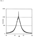
- FIG. 2 is an example of a chart obtained by X-ray crystal structure analysis
- FIG. 3 is an example of a pattern obtained by profile-fitting the chart of FIG. 2 ;
- FIG. 4 is a schematic diagram of a metal powder manufacturing apparatus
- FIG. 5 A is a transmission electron microscopy (TEM) image of a particle before a heat treatment
- FIG. 5 B is a high angle annular dark field scanning transmission electron microscopy (HAADF-STEM) image of a particle before the heat treatment;
- FIG. 5 C is an O-mapping image of a particle before the heat treatment
- FIG. 5 D is an Si-mapping image of a particle before a heat treatment
- FIG. 5 E is an Fe-mapping image of a particle before the heat treatment
- FIG. 5 F is a B-mapping image of a particle before the heat treatment
- FIG. 6 A is a TEM image of a particle after heat treatment
- FIG. 6 B is an HAADF-STEM image of a particle after the heat treatment
- FIG. 6 C is an O-mapping image of a particle after the heat treatment
- FIG. 6 D is an Si-mapping image of a particle after the heat treatment
- FIG. 6 E is an Fe-mapping image of a particle after the heat treatment.
- FIG. 6 F is a B-mapping image of a particle after the heat treatment.
- Soft magnetic metal powder according to the present embodiment has particles 1 each having a structure shown in FIG. 1 near the surface thereof.
- the soft magnetic metal powder according to the present embodiment has the particles 1 each including a soft magnetic metal portion 11 and a coating portion 13 coating the soft magnetic metal portion 11 .
- the coating portion 13 includes a first coating portion 13 a and a second coating portion 13 b , and the first coating portion 13 a is closer to the soft magnetic metal portion 11 than the second coating portion 13 b.
- No particular limitation is imposed on a method of checking whether the coating portion 13 has the first coating portion 13 a and the second coating portion 13 b .
- a method of checking by using TEM and an electron energy loss spectroscopy (EELS) as described later.
- the average grain size of the particles 1 in the soft magnetic metal powder may be in the range from 0.1 ⁇ m or more to 100 ⁇ m or less.
- the average value D 1 of the thickness of the first coating portion 13 a may be in the range from 0.5 nm or more to 20 nm or less
- the average value D 2 of the thickness of the second coating portion 13 b may be in the range from 0.5 nm or more to 20 nm or less.
- D 1 and D 2 may be calculated by determining the ranges of the first coating portion 13 a and the second coating portion 13 b by using TEM, fast Fourier transform processing (FFT) on a TEM image, EELS, and the like, measuring thicknesses at least at 50 places for each of the first coating portion 13 a and the second coating portion 13 b , and averaging the thicknesses.
- FFT fast Fourier transform processing
- the first coating portion 13 a and the second coating portion 13 b include oxides of at least one element selected from Si, Fe, and B as a main component. Specifically, the amount of the oxide over the entire first coating portion 13 a is 70 mass % or more, and the amount of the oxide over the entire second coating portion 13 b is 70 mass % or more.
- the coating portion 13 is not required to coat the entire surface of the soft magnetic metal portion 11 , and may coat at least 60% or more of the entire surface of the soft magnetic metal portion 11 .
- the coating portion 13 may include a third coating portion (not shown in FIG. 1 ) on the outside of the second coating portion 13 b.
- the average value D 3 of the thickness of the third coating portion may be set in the range from 5 nm or more to 100 nm or less.
- the third coating portion may be an SiO 2 glass coating or a phosphate glass coating. Further, the third coating portion may be formed of two or more layers which are made of different kinds of materials.
- the powder resistivity of the soft magnetic metal powder having the particles 1 increases.
- particles contained in the soft magnetic metal powder according to the present embodiment may have the structure of the particle 1 described above.
- particles of 50% or more on the number of basis with respect to all the particles contained in the soft magnetic metal powder may have the above-described structure of the particle 1 .
- the microstructure of the soft magnetic metal portion 11 is arbitrary.
- the soft magnetic metal portion 11 may have an amorphous structure, or may have a nanocrystal structure.
- Hcj can be reduced and thus the soft magnetic properties can be enhanced as compared with a case where the soft magnetic metal portion 11 has crystals larger than the nanocrystals.
- the nanocrystals are crystals whose crystal grain sizes are, for example, 0.1 nm or more and 100 nm or less. In particles containing nanocrystals, it is normal that multiple nanocrystals are contained in one particle. In other words, the grain size of the particle is different from the crystal grain size.
- the microstructure of the soft magnetic metal portion 11 can be checked by XRD.
- the microstructure of the soft magnetic metal portion 11 can be checked regardless of the microstructure of the coating portion 13 . This is because the existence ratio of the coating portion 13 is smaller than the existence ratio of the soft magnetic metal portion 11 , so that the microstructure of the coating portion 13 is not reflected in the measurement result by XRD.
- soft magnetic metal portions 11 included in soft magnetic metal powder in which an amorphization ratio X represented by the following equation (1) is 85% or more have amorphous structures
- soft magnetic metal portions 11 included in soft magnetic alloy powder in which the amorphization ratio X is less than 85% have a crystalline structure.
- X 100 ⁇ ( Ic /( Ic+Ia ) ⁇ 100) (1)
- the amorphization ratio X is determined by performing X-ray crystal structure analysis on soft magnetic alloy powder by XRD, identifying a phase, and reading peaks of crystallized Fe or compounds (Ic: crystalline scattering integrated intensity, Ia: amorphous scattering integrated intensity), estimating a crystallization rate from the peak intensities, and calculating the amorphization ratio X with the above equation (1).
- Ic crystalline scattering integrated intensity
- Ia amorphous scattering integrated intensity
- An X-ray crystal structure analysis is conducted on the soft magnetic alloy powder according to the present embodiment by XRD to obtain a chart as shown in FIG. 2 .
- This chart is subjected to profile fitting by using a Lorentz function of the following equation (2) to obtain a crystal component pattern ⁇ c indicating a crystalline scattering integrated intensity, an amorphous crystal pattern ⁇ a indicating an amorphous scattering integrated intensity, and a pattern ⁇ c+a of the combination of the crystal component pattern ⁇ c , and the amorphous crystal pattern ⁇ a as shown in FIG. 3 .
- the amorphization ratio X is determined from the crystalline scattering integrated intensity and the amorphous scattering integrated intensity of the obtained pattern according to the above equation (1).
- the error between the actually measured integrated intensity by XRD and the integrated intensity calculated by using the Lorentz function was set to be within 1% in the above range.
- the nanocrystals included in the soft magnetic metal portion 11 of the present embodiment may be Fe-based nanocrystals.
- the Fe-based nanocrystal is a crystal which has a nanometer-order grain size and has a crystal structure of Fe which is bcc (body-centered cubic lattice structure).
- bcc body-centered cubic lattice structure
- No particular limitation is imposed on a method of calculating the average crystal grain size of the Fe-based nanocrystals.
- the average crystal grain size can be calculated by observation using TEM.
- no particular limitation is imposed on a method for checking whether the crystal structure is bcc or not. For example, it can be checked by using XRD.
- the average crystal grain size of the Fe-based nanocrystal may be in the range of 5 to 30 nm.
- Soft magnetic metal powder containing such Fe-based nanocrystals tends to have a high Bs and a low Hcj. In other words, the soft magnetic properties thereof are easily enhanced.
- the coating portion 13 of the particle 1 included in the soft magnetic metal powder according to the present embodiment has a microstructure in which the first coating portion 13 a contains amorphous material and the second coating portion 13 b contains crystals.
- the second coating portion 13 b has a higher crystal content ratio than the first coating portion 13 a.
- the soft magnetic metal powder has enhanced powder resistivity while having excellent soft magnetic properties. Therefore, use of the soft magnetic metal powder of the present embodiment makes it easier to obtain green compact having high electric resistance.
- the first coating portion 13 a substantially includes only amorphous material.
- the first coating portion 13 a substantially includes only amorphous material, it is easy to obtain green compact having higher resistance. Note that the fact that the first coating portion 13 a is substantially made of only amorphous material means that no crystalline spot is observed from the first coating portion 13 a by FFT.
- the composition of the particle 1 except that it contains Fe.
- the particle 1 contains Fe, it makes it easy for the first coating portion 13 a and the second coating portion 13 b to include oxides containing Fe.
- the particle 1 contains Fe and B, it makes it easy to control the crystallinity of the first coating portion and the second coating portion.
- the particle 1 contains Si, it makes it easy to enhance the soft magnetic properties of the soft magnetic metal powder. Specifically, the soft magnetic metal powder tends to become soft magnetic metal powder having low Hcj and high Bs.
- the particle 1 may have, for example, a main component represented by a composition formula (Fe (1 ⁇ ( ⁇ + ⁇ )) X1 ⁇ X2 ⁇ ) (1 ⁇ (a+b+c+d+e+f)) M a B b P c Si d C e S f , where X1 is one or more selected from the group consisting of Co and Ni, X2 is one or more selected from the group consisting of Al, Mn, Ag, Zn, Sn, As, Sb, Cu, Cr, Bi, N, O, and a rare earth element, M is one or more selected from the group consisting of Nb, Hf, Zr, Ta, Mo, W, Ti and V, and the following inequalities may be satisfied:
- the soft magnetic metal powder having the above composition When the soft magnetic metal powder having the above composition is subjected to a heat treatment, Fe-based nanocrystals are easily deposited in the soft magnetic metal portion 11 .
- the soft magnetic metal powder having the above composition is easily made as a starting material for soft magnetic alloy powder having particles 1 each including the soft magnetic metal portion 11 in which the Fe-based nanocrystals are deposited. Since the existence ratio of the first coating portion 13 a and the second coating portion 13 b occupying the entire particle 1 are small, the composition of the particle 1 and the composition of the soft magnetic metal portion 11 are almost coincidence with each other.
- the soft magnetic metal portion 11 before the heat treatment may have a structure including only amorphous material, or may have a nano-heterostructure in which initial fine crystals exist in amorphous material.
- the initial fine crystals may have an average grain size ranging from 0.3 nm or more to 10 nm or less.
- the soft magnetic metal portion 11 has the structure including only amorphous material or the nano-heterostructure, the above-mentioned amorphization ratio X is 85% or more.
- the composition of the coating portion 13 is arbitrary.
- the coating portion 13 may contain B. This is because oxides containing B as a main component are easily contained in the first coating portion 13 a and the second coating portion 13 b .
- B A the average value of the concentration of B in the soft magnetic metal portion 11
- B B the average value of the concentration of B in the first coating portion 13 a and the second coating portion 13 b
- 0.5 ⁇ B B /B A ⁇ 10 may be satisfied
- 1.0 ⁇ B B /B A ⁇ 5.5 is preferably satisfied.
- B B /B A is within the above range, the powder resistivity tends to be enhanced.
- the coating portion 13 has the third coating portion, it is preferable that 1.0 ⁇ B B /B A ⁇ 3.0 is satisfied.
- 1.0 ⁇ B B /B A ⁇ 3.0 wettability of the third coating portion is enhanced, and the powder resistivity of the soft magnetic metal powder is increased.
- B A and B B can be measured by using EDX.
- B A is calculated, for example, by measuring and averaging the concentration of B for at least 20 points of the soft magnetic metal portion 11 .
- the concentration of B in the soft magnetic metal portion 11 is measured, the concentration of B is measured for a portion which is located at a distance of 10 nm or more from the coating portion 13 .
- B B is measured by the following method, for example. First, the concentration of B is measured and averaged for at least 20 points of the first coating portion 13 a to calculate an average value (B Ba ) of the concentration of B in the first coating portion 13 a . Next, the concentration of B is measured and averaged for at least 20 points of the second coating portion 13 b to calculate an average value (B Bb ) of the concentration of B in the second coating portion 13 b .
- D 1 +D 2 D
- the coating portion 13 may contain Si. This is because oxides containing Si are easily contained as a main component in the first coating portion 13 a and the second coating portion 13 b . Further, when the average value of the concentration of Si in the soft magnetic metal portion 11 is represented by Si A and the average value of the concentration of Si in the first coating portion 13 a and the second coating portion 13 b is represented by Si B , 0.5 ⁇ Si B /Si A ⁇ 50 may be satisfied, and it is preferable that 0.8 ⁇ Si B /Si A ⁇ 19.2 is satisfied. When Si B /Si A is within the above range, the powder resistivity tends to be enhanced.
- Si A and Si B may be measured in the same method as the above-described measurement method for B A and B B .
- the powder resistivity can be further enhanced by satisfying both of 1.0 ⁇ B B /B A ⁇ 5.5 and 0.8 ⁇ Si B /Si A ⁇ 19.2.
- a method of manufacturing the soft magnetic metal powder according to the present embodiment will be described below, but the method of manufacturing the soft magnetic metal powder is not limited to the following method.
- the soft magnetic metal powder according to the present embodiment can be manufactured, for example, by a gas atomization method. Particularly, when the soft magnetic metal powder is manufactured by the gas atomization method using a metal powder manufacturing apparatus 100 shown in FIG. 4 , the obtained soft magnetic metal powder includes particles 1 each having the first coating portion 13 a and the second coating portion 13 b described above.
- the metal powder manufacturing apparatus 100 shown in FIG. 4 is an apparatus for pulverizing molten metal 21 by the gas atomization method to obtain the particles 1 described above.
- the metal powder manufacturing apparatus 100 includes a molten metal supply unit 20 and a cooling unit 30 disposed below the molten metal supply unit 20 in a vertical direction.
- the vertical direction in FIG. 4 is a direction along the Z axis.
- the molten metal supply unit 20 includes a heat-resistant container 22 for accommodating molten metal 21 therein.
- a heating coil 24 is arranged on the outer periphery of the heat-resistant container 22 to heat the molten metal 21 accommodated in the container 22 and maintain the molten metal 21 in a molten state.
- a discharge port is formed at the bottom of the container 22 , and the molten metal 21 is discharged as dropped molten metal 21 a through the discharge port to an inner surface 33 of a cylindrical body 32 constituting the cooling unit 30 .
- a gas injection nozzle 26 is arranged at an outside portion of an outer bottom wall of the container 22 so as to surround the discharge port.
- the gas injection nozzle 26 includes a gas injection port.
- a high-pressure gas (for example, a gas having an injection pressure of 3 MPa or more and 10 MPa or less) is injected from the gas injection port to the dropped molten metal 21 a discharged from the discharge port.
- the high-pressure gas is injected obliquely downward from the entire circumference of the molten metal discharged from the discharge port 23 , whereby the dropped molten metal 21 a becomes a large number of droplets, and flows along the gas flow to the inner surface of the cylindrical body 32 .
- the composition of the molten metal 21 is set to the same composition as the soft magnetic metal portion 11 of the particles 1 finally obtained.
- the composition of the molten metal 21 is set to the above-described composition, the surfaces of the particles 1 are easily oxidized by coming into contact with oxygen in the atmosphere for a short time. As a result, the coating portions 13 are formed on the particles 1 . In other words, the thickness of the coating portion 13 can be controlled by controlling the oxygen concentration in the atmosphere.
- the metal powder manufacturing apparatus 100 uses an inert gas as the gas to be injected from the gas injection port of the gas injection nozzle 26 , so that even the molten metal 21 that is easily oxidized can be easily pulverized.
- an inert gas such as nitrogen gas, argon gas, or helium gas, or a reducing gas such as ammonia decomposition gas is preferable as the gas injected from the gas injection port.
- Air may be used depending on the easiness of oxidation of the molten metal 21 .
- the center axis O of the cylindrical body 32 is inclined at a predetermined angle ⁇ 1 with respect to the vertical line Z.
- the predetermined angle ⁇ 1 is not particularly limited, but is preferably 0° to 45°.
- the dropped molten metal 21 a discharged to the inverted conical coolant flow 50 impacts against the coolant flow 50 to be further divided and made finer, and also is cooled and solidified to become solid-state soft magnetic metal powder.
- a discharge portion 34 is provided on a lower side along the center axis O of the cylindrical body 32 so that the soft magnetic metal powder contained in the coolant flow 50 can be discharged to the outside together with the coolant.
- the soft magnetic metal powder discharged together with the coolant is separated from the coolant and taken out in an external storage tank or the like. Note that no particular limitation is imposed on the coolant, but cooling water is used.
- a coolant lead-in portion (coolant lead-out portion) 36 for leading the coolant into the inside of the cylindrical body 32 is provided to an upper portion of the cylindrical body 32 in the direction of the center axis O.
- the coolant lead-in portion 36 can also be defined as a coolant lead-out portion from the viewpoint that the coolant is discharged from the upper portion of the cylindrical body 32 to the inside of the cylindrical body 32 .
- the coolant lead-in portion 36 includes at least a frame body 38 , and also includes an external portion (outer space portion) 44 located at the outside in the radial direction of the cylindrical body 32 and an internal portion (inner space portion) 46 located at the inside in the radial direction of the cylindrical body 32 inside the coolant lead-in portion 36 .
- the external portion 44 and the internal portion 46 are partitioned by a partition portion 40 , and the external portion 44 and the internal portion 46 are made to intercommunicate with each other through a passage portion 42 which is formed above the partition portion 40 in the direction of the center axis O so that the coolant can flow therebetween. As shown in FIG.
- the partition portion 40 is inclined at an angle of ⁇ 2 with respect to the center axis O.
- the angle ⁇ 2 is preferably in the range of 0° to 90°, and more preferably 0° to 45°.
- the wall surface of the partition portion 40 is preferably flush with the inner surface 33 of the cylindrical body 32 .
- the wall surface of the partition portion 40 is not necessarily flush with the inner surface 33 of the cylindrical body 32 , and may be slightly inclined or have a step with respect to the inner surface 33 of the cylindrical body 32 .
- a single or a plurality of nozzles 37 are connected to the external portion 44 so that the coolant is taken into the external portion 44 from the nozzle(s) 37 . Further, a coolant discharge portion 52 is formed below the internal portion 46 in the direction of the center axis O, and the coolant in the internal portion 46 is discharged (led out) therefrom to the inside of the cylindrical body 32 .
- the frame body 38 of the coolant lead-in portion 36 is arranged at the upper portion of the cylindrical body 32 in the direction of the center axis O, and has a cylindrical shape having an outer diameter smaller than the inner diameter of the cylindrical body 32 .
- the outer peripheral surface of the frame body 38 serves as a flow-path inner peripheral surface for guiding the flow of the coolant in the internal portion 46 .
- the external portion 44 and the internal portion 46 intercommunicate with each other by a passage portion 42 provided above the partition portion 40 in the direction of the center axis O.
- the passage portion 42 is a gap between an upper plate portion of the coolant lead-in portion 36 and an upper end of the partition portion 40 , and the vertical width W 1 in the direction of the center axis O of the passage portion 42 (see FIG. 4 ) is smaller than the vertical width W 2 in the direction of the center axis O of the external portion 44 .
- W 1 /W 2 is preferably 1 ⁇ 3 or less, more preferably 1 ⁇ 4 or less.
- the nozzle 37 is connected to the external portion 44 of the coolant lead-in portion 36 .
- the coolant intrudes into the external portion 44 in the coolant lead-in portion 36 from the nozzle 37 .
- the coolant that has intruded into the external portion 44 passes through the passage portion 42 and intrudes into the internal portion 46 .
- the frame body 38 has an inner diameter smaller than the inner surface 33 of the cylindrical body 32 .
- the coolant discharge portion 52 is formed in a gap between an outer convex portion at the lower end of the frame body 38 and the inner surface 33 of the cylindrical body 32 .
- the width in the radial direction of the coolant discharge portion is larger than the vertical width W 1 of the passage portion.
- the inner diameter of the coolant discharge portion 52 is coincident with the maximum outer diameter of a flow path deflection surface, and the outer diameter of the coolant discharge portion 52 is substantially coincident with the inner diameter of the cylindrical body 32 . Further, the outer diameter of the coolant discharge portion 52 may be made coincident with the inner surface 33 of the cylindrical body 32 . Note that the inner diameter of the inner surface 33 of the cylindrical body 32 is not particularly limited, but is preferably 50 to 500 mm.
- the coolant that is temporarily stored in the external portion 44 from the nozzle 37 , and passes through the passage portion 42 , and then intrudes into the internal portion 46 forms a flow directing downward in the direction of the center axis O along the flow-path inner peripheral surface of the frame body 38 .
- the coolant flowing downward in the direction of the center axis O along the flow-path inner peripheral surface inside the internal portion 46 subsequently flows along the flow path deflection surface of the frame body 38 , and impacts with and reflects from the inner surface 33 of the cylindrical body 32 .
- the coolant is discharged in an inverted conical shape from the coolant discharge portion 52 into the cylindrical body 32 , thereby forming a coolant flow 50 .
- the coolant flow 50 flowing out of the coolant discharge portion 52 is an inverted conical flow that travels straightly from the coolant discharge portion 52 to the center axis O, but it may be a spiral inverted conical flow.
- the length L 1 in the axial direction of the frame body 38 may be set to the extent that it covers the width W 1 of the passage portion 42 in the direction of the center axis O.
- the coolant that has intruded from the nozzle 37 into the external portion 44 is temporarily stored in the external portion 44 , and then passes therefrom through the passage 42 to increase the flow rate thereof, and intrudes into the internal portion 46 .
- the coolant that has passed through the passage 42 impacts against a curvature surface formed on the inner peripheral surface of the flow path of the frame body 38 , and the direction of the coolant flow is changed to a downward flow along the center axis O.
- the flow rate of the coolant flowing downward along the center axis O in the internal portion 46 increases because the cross section of the flow path is narrowed.
- the coolant impacts against and reflects from the inner surface of the cylindrical body 32 in a state where the flow rate is increased, and discharged from the coolant discharge portion 52 into the cylindrical body 32 in an inverted conical shape as shown in FIG. 4 , thereby forming the coolant flow 50 .
- Droplets of the dropped molten metal 21 a shown in FIG. 4 are incident to the upper liquid surface of the inverted conical coolant flow 50 formed as described above, and the droplets of the dropped molten metal 21 a flows together with the coolant and is cooled in the coolant flow 50 .
- an inlet for droplets of the dropped molten metal 21 a is formed at the upper opening portion of the cylindrical body 32 , and a coolant flow 50 having an inverted conical shape is formed at the upper opening portion of the cylindrical body 32 .
- the coolant flow 50 having the inverted conical shape has been formed at the upper opening portion of the cylindrical body 32 , and the coolant is discharged from the discharge portion 34 of the cylindrical body 32 , whereby a suction pressure into the inside of the cylindrical body 32 is obtained at the upper opening portion of the cylindrical body 32 .
- the suction pressure having a pressure difference of 30 kPa or more from the outside of the cylindrical body 32 is obtained.
- the droplets of the dropped molten metal 21 a are sucked into the inside of the cylindrical body 32 from the upper opening portion of the cylindrical body 32 in a self-alignment manner (the droplets are automatically sucked even if they are slightly displaced), and taken into the inverted conical coolant flow 50 . Therefore, the flight time of the droplets of the dropped molten metal 21 a from the discharge port of the molten metal supply unit 20 to the coolant flow 50 is relatively shortened. As the flight time is shortened, the droplets of the dropped molten metal 21 a are more difficult to be oxidized. Further, a quenching effect is promoted, and the soft magnetic metal portion 11 is likely to have an amorphous structure.
- the droplets of the dropped molten metal 21 a are taken into, not the flow of the coolant along the inner surface 33 of the cylindrical body 32 , but the flow of the inverted conical coolant, so that the retention time of the cooled particles 1 can be shortened in the cylindrical body 32 , and the damage to the inner surface 33 of the cylindrical body 32 is also small. Further, the damage to the cooled particles themselves is also small.
- the present embodiment there is no need to machine the inner surface 33 of the cylindrical body 32 , and there is no need to attach anything. Only by attaching the coolant lead-out portion 36 to the upper portion of the cylindrical body 32 , the inverted conical coolant flow 50 can be formed. Further, the inner diameter of the upper opening portion of the cylindrical body 32 can be made sufficiently large.
- the cooling rate of the powder 1 can be increased as compared with a case where a conventional metal powder manufacturing apparatus is used.
- a water pressure at the time when the coolant is jetted from the coolant discharge portion 52 is referred to as “atomization water pressure”.
- atomization water pressure a water pressure at the time when the coolant is jetted from the coolant discharge portion 52
- the flow rate of the coolant flow 50 increases, and the coolant flow 50 becomes thinner.
- the cooling rate of the particles 1 further increases. Also, as the coolant flow 50 is thinner, a time during which the particles 1 are exposed to oxygen in the atmosphere is longer.
- the coating portion 13 can have the first coating portion 13 a and the second coating portion 13 b which are different in the microstructure from each other.
- the conventional metal powder manufacturing apparatus is used or when the atomization water pressure is too low, it is difficult for the coating portion 13 to have the first coating portion 13 a and the second coating portion 13 b . In other words, it is difficult to obtain the soft magnetic metal powder according to the present embodiment.
- a heat treatment may be conducted on the soft magnetic metal powder according to the present embodiment obtained by using the metal powder manufacturing apparatus 100 .
- the heat treatment may be conducted at 400° C. to 700° C. for 0.1 to 10 hours.
- the iron oxide component of the coating portion 13 is reduced, and some of crystals of the second coating portion 13 b are easily amorphized, so that the second coating portion 13 b easily has a microstructure including both of crystals and amorphous material.
- the microstructure in the soft magnetic metal powder is easily changed to a structure having nanocrystals from the structure having only the amorphous material or the nano-heterostructure in which the initial fine crystals exist in the amorphous material.
- Hcj of the soft magnetic metal powder tends to decrease. Note that when the temperature of the heat treatment is too high, Hcj of the soft magnetic metal powder tends to increase.
- FIGS. 5 A to 5 F show examples of the particles 1 contained in the soft magnetic metal powder before the heat treatment.
- FIG. 5 A shows a TEM image near the surface of particle 1
- FIG. 5 B shows an HAADF-STEM image near the surface of particle 1
- FIG. 5 C shows an O-mapping image near the surface of particle 1 by EELS
- FIG. 5 D shows an Si-mapping image near the surface of the particle 1 by EELS
- FIG. 5 E shows an Fe-mapping image near the surface of the particle 1 by EELS
- FIG. 5 F shows a B-mapping image near the surface of the particle 1 by EELS.
- FIGS. 5 A shows a TEM image near the surface of particle 1
- FIG. 5 B shows an HAADF-STEM image near the surface of particle 1
- FIG. 5 C shows an O-mapping image near the surface of particle 1 by EELS
- FIG. 5 D shows an Si-mapping image near the surface of the particle 1 by EE
- FIG. 5 A to 5 F show images obtained by mixing the soft magnetic metal powder according to the present embodiment with resin 15 and producing a dust core by a well-known method, and observing cross-sections of the dust core.
- the first coating portion 13 a and the second coating portion 13 b in FIG. 5 A were distinguished from each other by FFT. Further, the first coating portion 13 a in FIG. 5 A includes only amorphous material, and the second coating portion 13 b includes only crystals.
- FIGS. 6 A to 6 F show examples of the particles 1 contained in the soft magnetic metal powder after the heat treatment.
- the soft magnetic metal powder containing the particles 1 shown in FIGS. 6 A to 6 F is obtained by conducting the heat treatment on the soft magnetic metal powder containing the particles 1 shown in FIGS. 5 A to 5 F .
- FIG. 6 A shows a TEM image near the surface of the particle 1
- FIG. 6 B shows a HAADF-STEM image near the surface of particle 1
- FIG. 6 C shows an O-mapping image near the surface of particle 1 by EELS
- FIG. 6 D shows an Si-mapping image near the surface of the particle 1 by EELS
- FIG. 6 E shows an Fe-mapping image near the surface of the particle 1 by EELS
- FIG. 6 F shows a B-mapping image near the surface of the particle 1 by EELS
- FIGS. 6 A to 6 F show images obtained by mixing the soft magnetic metal powder according to the present embodiment with resin 15 and preparing a dust core by a well-known method, and observing cross-sections of the dust core.
- the first coating portion 13 a and the second coating portion 13 b in FIG. 6 A were distinguished from each other by FFT.
- the first coating portion 13 a in FIG. 6 A is composed of only amorphous material
- the second coating portion 13 b is composed of both of amorphous material and crystals.
- FIGS. 5 A to 5 F By comparing FIGS. 5 A to 5 F with FIGS. 6 A to 6 F , it can be understood that Fe in the coating portion 13 is reduced by the heat treatment. Due to the reduction of Fe, particularly the crystallinity of the second coating portion 13 b is deteriorated, and thus some of the crystals before the heat treatment are amorphized. Further, the second coating portion 13 b has a microstructure including both of amorphous material and crystals. Note that FIGS. 5 A to 5 F show a sample number 1 described later, and FIGS. 6 A to 6 F show a sample number 6 described later.
- the third coating portion may be formed in the particle 1 .
- No particular limitation is imposed on a method of forming the third coating portion.
- the third coating portion may be formed by using an insulating coating commonly used in the art.
- the type of coating material to be used for the insulating coating may be used for the insulating coating.
- P 2 O 5 -based glass, Bi 2 O 3 -based glass, and B 2 O 3 —SiO 2 -based glass may be used.
- the glass to be used as the coating material may be powdered glass.
- P 2 O 5 -based glass is preferably glass containing P 2 O 5 of 50 mass % or more. No particular limitation is imposed on the type of P 2 O 5 -based glass. For example, P 2 O 5 —ZnO—R 2 O—Al 2 O 3 -based glass may be used. Note that “R” represents alkali metal.
- Bi 2 O 3 -based glass Glass containing Bi 2 O 3 of 50 mass % or more is preferably used as Bi 2 O 3 -based glass.
- type of Bi 2 O 3 -based glass For example, bismuthate-based glass may be used.
- the bismuthate-based glass include Bi 2 O 3 —ZnO—B 2 O 3 —SiO 2 -based glass.
- Glass containing B 2 O 3 of 10 mass % or more and SiO 2 of 10 mass % or more is preferably used as B 2 O 3 —SiO 2 -based glass.
- B 2 O 3 —SiO 2 -based glass No particular limitation is imposed on the type of B 2 O 3 —SiO 2 -based glass.
- borosilicate glass may be used. Examples of the borosilicate glass include BaO—ZnO—B 2 O 3 —SiO 2 —Al 2 O 3 -based glass.
- the soft magnetic metal powder according to the present embodiment has been described above, but the soft magnetic metal powder according to the present invention is not limited to the above-described embodiment.
- the soft magnetic metal powder of the present invention No particular limitation is imposed on the use of the soft magnetic metal powder of the present invention.
- magnetic components such as an inductor, a choke coil, and a transformer may be used.
- Soft magnetic metal powder including the following composition 1 or composition 2 was produced as the soft magnetic metal powder.
- the composition 1 is represented by Fe 0.735 Nb 0.03 B 0.09 Si 0.135 Cu 0.01 in atomic ratio.
- the composition 2 is represented by Fe 0.800 Nb 0.060 B 0.090 P 0.050 in atomic ratio.
- the soft magnetic metal powder was produced by a gas atomization method using the metal powder manufacturing apparatus 100 shown in FIG. 4 .
- the melting temperature was set to 1500° C.
- the injection gas pressure of the molten metal was set to 5 MPa
- the gas used was Ar.
- the gas atomization water pressure is shown in Table 1.
- the inner diameter of the inner surface of the cylindrical body 32 was set to 300 nm
- W 1 /W 2 was set to 0.25
- ⁇ 1 was set to 20°
- ⁇ 2 was set to 0°.
- Conditions other than the above condition were appropriately controlled so that the average grain size (D50) of the obtained soft magnetic metal powder was 24 ⁇ m.
- the heat treatment was conducted on the soft magnetic metal powder.
- the heat treatment was conducted at 600° C. for 1 hour.
- the atmosphere under the heat treatment was an Ar atmosphere.
- the average grain size (D50) of the obtained soft magnetic metal powder was measured, and it was confirmed that all the measured average grain sizes were equal to 24 ⁇ m.
- the average particle size was measured by using a dry type particle size distribution measurement instrument (HELOS).
- Hcj, Bs and powder resistivity ⁇ of the soft magnetic metal powder of each of the examples and comparative examples were measured.
- Hcj was measured by an Hc meter.
- Bs was measured at 1000 kA/m by using a vibrating sample magnetometer (VSM), and ⁇ was measured at a pressure of 0.6 t/cm 2 by a powder resistance measurement device.
- VSM vibrating sample magnetometer
- ⁇ was measured at a pressure of 0.6 t/cm 2 by a powder resistance measurement device.
- ⁇ was equal to 10 2 ⁇ cm or more was evaluated as A
- a case where ⁇ was 10 ⁇ 1 ⁇ cm or more and less than 10 2 ⁇ cm was evaluated as B
- a case where ⁇ was less than 10 ⁇ 1 ⁇ cm was evaluated as C
- a measurement result is shown in Table 1.
- the powder resistivity was determined to be good
- the evaluation was A the powder resistivity was determined to be particularly good.
- the coating portions included in the soft magnetic metal powders of the respective examples and comparative examples were observed.
- a bright field image near the particle surface was observed by using TEM, and it was confirmed that the coating portion existed on the particle surface.
- a mapping image for each element was observed by using EELS, and it was observed whether or not the coating portion included the first coating portion and the second coating portion. It was confirmed that the coating portions of sample numbers 1 to 10 contained an oxide of Fe, an oxide of B, and an oxide of Si. It was confirmed that the coating portions of sample numbers 11 to 20 contained an oxide of Fe and an oxide of B.
- each coating portion included crystals and amorphous material by using FFT.
- a result is shown in Table 1.
- “amorphous” was written in the column of crystallinity.
- “crystal” was written in the column of crystallinity.
- “crystal+amorphous” was written in the column of crystallinity.
- the coating portion is not composed of the first coating portion and the second coating portion, in Table 1, the coating portion is described to be included only the second coating portion when the entire coating portion includes crystals substantially uniformly, and the coating portion is described to be included only the first coating portion when the entire coating portion includes only amorphous material.
- the average thicknesses D 1 and D 2 of the respective coating portions were calculated by determining the boundary between the first coating portion and the second coating portion by using TEM, FFT, and EELS. A result is shown in Table 1.
- B A , B B , Si A , and Si B were calculated by measuring the concentration of B and the concentration of Si of each of the first coating portion and the second coating portion by using EDX in addition to the above-described equipment. Further, B B /B A and Si B /Si A were calculated. Results are shown in Table 1. Note that Si A and Si B were not measured for sample numbers 11 to 20 containing no Si.
- Each of the examples has excellent soft magnetic properties which are the same level as comparative examples having the same configuration as each example except that the entire coating portion included only amorphous material or included only crystals. Further, each of the examples has an excellent ⁇ as compared with comparative examples having the same configuration as each of the examples except that the entire coating portion included only amorphous material or included only crystals.
- Soft magnetic metal powder was produced and evaluated in the same manner as that in Experimental Example 1 except that the composition of the soft magnetic metal powder was changed to the composition shown in Table 2. Results are shown in Table 2.
- the atomization water pressure was set to 10 MPa for all the examples. All the evaluations of ⁇ were A evaluations. Furthermore, it was confirmed for samples containing Si and B that the coating portion contained oxides of Si, Fe, and B. For samples which did not contain Si, but contained B, it was confirmed that the coating portion contained oxides of Fe and B.
- the examples in which the atomization water pressure was high acquired soft magnetic metal powder containing particles each having a structure in which the coating portion included the first coating portion and the second coating portion, and the first coating portion was closer to the soft magnetic metal portion than the second coating portion. Further, the examples acquired soft magnetic metal powder containing particles each having a structure in which the first coating portion and the second coating portion had oxides including at least one element selected from Si, Fe and B as a main component, the first coating portion included only amorphous material, and the second coating portion included crystals.
- Soft magnetic metal powder was produced and evaluated in the same manner as that in the sample number 11 of Experimental Examples 1 and 2 except that the kind of M element was changed from Nb to other elements for the sample number 11 of Experimental Examples 1 and 2. Results are shown in Table 3. Note that all evaluations of ⁇ were A evaluations. Furthermore, it was confirmed that the coating portion included oxides containing Fe and B.
- Soft magnetic metal powder was produced and evaluated in the same manner as that in the sample number 11 of Experimental Examples 1 and 2 except that the types and amounts of X1 and X2 elements were changed for the sample number 11 of Experimental Examples 1 and 2. Results are shown in Table 4. Note that all evaluations of ⁇ were A evaluations. Furthermore, it was confirmed that the coating portion included oxides containing Fe and B.
- the microstructure of the soft magnetic metal portion was checked by using XRD and TEM for all the examples written in Tables 1 to 4. For all the examples on which no heat treatment was conducted, it was confirmed that the soft magnetic metal portion had a structure including only amorphous material or a nano-heterostructure. For all the examples on which the heat treatment was conducted, it was confirmed that the soft magnetic metal portion had a structure including only nanocrystals.
- an insulating coating including an SiO 2 glass coating or a phosphate glass coating was applied to soft magnetic alloy powder of sample numbers 6, 7, 8, 16, 17, and 18 by using a coating material made of powdered glass of types shown in Table 5 to form the third coating portion.
- the average value D 3 of the thickness of the third coating portion was set to about 20 nm.
- the concentration of B and the concentration of Si of each of the first and second coating portions, and the thicknesses (D 1 , D 2 , D 3 ) of the respective coating portions were measured in the same manner as in Experimental Examples 1 to 4.
- Table 5 shows test results of soft magnetic alloy powder before coating (sample numbers 6, 7, 8, 16, 17, 18). From Table 5, it was confirmed that the concentration of B and the concentration of Si of each coating portion, and the thickness of each coating portion did not change significantly before and after coating. Note that Table 5 also shows results of Experimental Example 6 and Sample number 121 described below for reference.
- P 2 O 5 —ZnO—R 2 O—Al 2 O 3 -based powdered glass used as the coating material in this example contained P 2 O 5 of 50 mass %, ZnO of 12 mass %, R 2 O of 20 mass %, and Al 2 O 3 of 6 mass %, and other components as a remaining part.
- the present inventors also conducted a similar test on a case where P 2 O 5 -based glass having a composition different from that of the above-described P 2 O 5 —ZnO—R 2 O—Al 2 O 3 -based powdered glass was used, and confirmed that a test result similar to a test result obtained in the case of use of the P 2 O 5 —ZnO—R 2 O—Al 2 O 3 -based powdered glass described later was obtained.
- Bi 2 O 3 —ZnO—B 2 O 3 —SiO 2 -based powdered glass used as the coating material in this example contained Bi 2 O 3 of 80 mass %, ZnO of 10 mass %, B 2 O 3 of 5 mass %, and SiO 2 of 5 mass %.
- the present inventors also conducted a similar test on a case where bismuthate-based glass having a composition different from that of the above-mentioned Bi 2 O 3 —ZnO—B 2 O 3 —SiO 2 -based powdered glass was used, and confirmed that a test result similar to a test result obtained in the case of use of the Bi 2 O 3 —ZnO—B 2 O 3 —SiO 2 -based powdered glass described later was obtained.
- BaO—ZnO—B 2 O 3 —SiO 2 —Al 2 O 3 -based powdered glass used as the coating material in this example contained BaO of 8 mass %, ZnO of 23 mass %, B 2 O 3 of 19 mass %, SiO 2 of 16 mass %, and Al 2 O 3 of 6 mass %, and other components as the remaining part.
- the present inventors also conducted a similar test on a case where borosilicate-based glass having a composition different from that of the above-described BaO—ZnO—B 2 O 3 —SiO 2 —Al 2 O 3 -based powdered glass was used, and confirmed that a test result similar to a test result obtained in the case of use of the BaO—ZnO—B 2 O 3 —SiO 2 —Al 2 O 3 -based powdered glass described later was obtained.
- the powder resistivity and the coercivity Hcj of the soft magnetic alloy powder after the third coating portion was formed were measured. With respect to the powder resistivity, unlike Tables 1 to 4, the measured values thereof are shown in Table 5.
- soft magnetic alloy powder of sample numbers 101 to 109 having the third coating portion formed therein had greatly enhanced powder resistivity as compared with soft magnetic alloy powder of sample numbers 6 to 8 of Experimental Example 1 produced in the same method except that no third coating portion was formed.
- soft magnetic alloy powder of sample numbers 110 to 118 and 121 having the third coating portion formed therein had a greatly enhanced powder resistivity as compared with soft magnetic alloy powder of sample numbers 16 to 18 of Experimental Example 1 produced by the same method except that no third coating portion was formed.
- soft magnetic alloy powder in which B B /B A was not less than 1.0 and not more than 3.0 had increased powder resistivity as compared with soft magnetic alloy powder having the same composition, microstructure, and coating material except that B B /B A was out of the above-mentioned range.
- the average value of the thickness of the layer made of P 2 O 5 —ZnO—R 2 O—Al 2 O 3 was set to about 20 nm
- the average value of the thickness of the layer made of BaO—ZnO—B 2 O 3 —SiO 2 —Al 2 O 3 was set to about 20 nm.
- the soft magnetic alloy powder of sample number 121 was produced under the same condition as that of sample number 110 except that D 3 was set to about 40 nm. A result is shown in Table 6.
- the soft magnetic alloy powder of sample number 120 in which the third coating portion was formed of two layers had higher powder resistivity as compared with the soft magnetic alloy powder of sample number 121 having a configuration similar to the configuration of sample number 120 except that the third coating portion was formed of only one layer.
- Sample number 121 has a structure in which BaO—ZnO—B 2 O 3 —SiO 2 —Al 2 O 3 of sample number 120 is replaced with P 2 O 5 —ZnO—R 2 O—Al 2 O 3 .
- P 2 O 5 —ZnO—R 2 O—Al 2 O 3 has a greater effect of increasing the powder resistivity of the soft magnetic alloy powder than BaO—ZnO—B 2 O 3 —SiO 2 —Al 2 O 3 .
- sample number 121 increases the powder resistivity as compared with sample number 120.
- sample number 120 increases the powder resistivity as compared with sample number 121. This is because the powder resistivity is improved by forming the third coating portion of two layers.
Landscapes
- Chemical & Material Sciences (AREA)
- Engineering & Computer Science (AREA)
- Power Engineering (AREA)
- Dispersion Chemistry (AREA)
- Materials Engineering (AREA)
- Mechanical Engineering (AREA)
- Metallurgy (AREA)
- Organic Chemistry (AREA)
- Physics & Mathematics (AREA)
- Electromagnetism (AREA)
- Crystallography & Structural Chemistry (AREA)
- Inorganic Chemistry (AREA)
- Soft Magnetic Materials (AREA)
- Powder Metallurgy (AREA)
Applications Claiming Priority (4)
| Application Number | Priority Date | Filing Date | Title |
|---|---|---|---|
| JP2019064223 | 2019-03-28 | ||
| JP2019-064223 | 2019-03-28 | ||
| JP2020-022600 | 2020-02-13 | ||
| JP2020022600A JP7359021B2 (ja) | 2019-03-28 | 2020-02-13 | 軟磁性金属粉末および磁性部品 |
Publications (2)
| Publication Number | Publication Date |
|---|---|
| US20200306831A1 US20200306831A1 (en) | 2020-10-01 |
| US11739403B2 true US11739403B2 (en) | 2023-08-29 |
Family
ID=72606625
Family Applications (1)
| Application Number | Title | Priority Date | Filing Date |
|---|---|---|---|
| US16/829,074 Active 2041-07-11 US11739403B2 (en) | 2019-03-28 | 2020-03-25 | Soft magnetic metal powder and magnetic component |
Country Status (2)
| Country | Link |
|---|---|
| US (1) | US11739403B2 (zh) |
| CN (1) | CN111755197B (zh) |
Families Citing this family (2)
| Publication number | Priority date | Publication date | Assignee | Title |
|---|---|---|---|---|
| JP6429055B1 (ja) * | 2018-03-09 | 2018-11-28 | Tdk株式会社 | 軟磁性金属粉末、圧粉磁心および磁性部品 |
| CN116670314A (zh) * | 2021-05-20 | 2023-08-29 | 华为技术有限公司 | 用于制造磁体的磁性粉末、磁体和磁性元件 |
Citations (14)
| Publication number | Priority date | Publication date | Assignee | Title |
|---|---|---|---|---|
| JP3342767B2 (ja) | 1994-03-28 | 2002-11-11 | アルプス電気株式会社 | Fe基軟磁性合金 |
| US20040140016A1 (en) * | 2002-04-05 | 2004-07-22 | Hiroaki Sakamoto | Iron-base amorphous alloy thin strip excellent in soft magnetic properties, iron core manufactured by using said thin strip, and |
| US20110272065A1 (en) * | 2009-01-20 | 2011-11-10 | Hitachi Metals, Ltd. | Soft magnetic alloy ribbon and its production method, and magnetic device having soft magnetic alloy ribbon |
| US20120082844A1 (en) * | 2010-09-30 | 2012-04-05 | Tdk Corporation | Powder magnetic core |
| US20150332823A1 (en) | 2014-05-14 | 2015-11-19 | Tdk Corporation | Soft magnetic metal powder and soft magnetic metal powder core using the same |
| US20160151836A1 (en) * | 2013-08-07 | 2016-06-02 | Panasonic Intellectual Property Management Co., Ltd. | Composite magnetic material, coil component using same, and power supply device |
| US20170032880A1 (en) | 2015-07-31 | 2017-02-02 | Samsung Electro-Mechanics Co., Ltd. | Magnetic powder and coil electronic component containing the same |
| JP6075605B2 (ja) | 2012-09-14 | 2017-02-08 | アイシン精機株式会社 | 軟磁性体及びその製造方法 |
| JP2018011043A (ja) | 2016-06-30 | 2018-01-18 | 太陽誘電株式会社 | 磁性材料及び電子部品 |
| KR20180034532A (ko) | 2015-07-31 | 2018-04-04 | 제이에프이 스틸 가부시키가이샤 | 연자성 압분 자심의 제조 방법 및 연자성 압분 자심 |
| US20180374619A1 (en) * | 2017-06-26 | 2018-12-27 | Taiyo Yuden Co., Ltd. | Magnetic material, electronic component, and method for manufacturing magnetic material |
| US20190013127A1 (en) * | 2017-07-05 | 2019-01-10 | Panasonic Intellectual Property Management Co., Ltd. | Soft magnetic powder, method for producing same, and dust core using soft magnetic powder |
| JP2019024076A (ja) | 2017-07-05 | 2019-02-14 | パナソニックIpマネジメント株式会社 | 軟磁性粉末とその製造方法、および、それを用いた圧粉磁心 |
| US20210313100A1 (en) * | 2020-03-27 | 2021-10-07 | Murata Manufacturing Co., Ltd. | Metal magnetic particle, inductor, method for manufacturing metal magnetic particle, and method for manufacturing metal magnetic core |
Family Cites Families (1)
| Publication number | Priority date | Publication date | Assignee | Title |
|---|---|---|---|---|
| JP6744534B2 (ja) * | 2016-10-27 | 2020-08-19 | 株式会社東北マグネットインスティテュート | 複合磁性粒及び磁性部品 |
-
2020
- 2020-03-19 CN CN202010198847.0A patent/CN111755197B/zh active Active
- 2020-03-25 US US16/829,074 patent/US11739403B2/en active Active
Patent Citations (20)
| Publication number | Priority date | Publication date | Assignee | Title |
|---|---|---|---|---|
| JP3342767B2 (ja) | 1994-03-28 | 2002-11-11 | アルプス電気株式会社 | Fe基軟磁性合金 |
| US20040140016A1 (en) * | 2002-04-05 | 2004-07-22 | Hiroaki Sakamoto | Iron-base amorphous alloy thin strip excellent in soft magnetic properties, iron core manufactured by using said thin strip, and |
| US20110272065A1 (en) * | 2009-01-20 | 2011-11-10 | Hitachi Metals, Ltd. | Soft magnetic alloy ribbon and its production method, and magnetic device having soft magnetic alloy ribbon |
| US20120082844A1 (en) * | 2010-09-30 | 2012-04-05 | Tdk Corporation | Powder magnetic core |
| JP6075605B2 (ja) | 2012-09-14 | 2017-02-08 | アイシン精機株式会社 | 軟磁性体及びその製造方法 |
| US20160151836A1 (en) * | 2013-08-07 | 2016-06-02 | Panasonic Intellectual Property Management Co., Ltd. | Composite magnetic material, coil component using same, and power supply device |
| JP2015233118A (ja) | 2014-05-14 | 2015-12-24 | Tdk株式会社 | 軟磁性金属粉末、およびその粉末を用いた軟磁性金属圧粉コア |
| US20150332823A1 (en) | 2014-05-14 | 2015-11-19 | Tdk Corporation | Soft magnetic metal powder and soft magnetic metal powder core using the same |
| US20210031268A1 (en) | 2015-07-31 | 2021-02-04 | Jfe Steel Corporation | Method of manufacturing soft magnetic dust core |
| US20170032880A1 (en) | 2015-07-31 | 2017-02-02 | Samsung Electro-Mechanics Co., Ltd. | Magnetic powder and coil electronic component containing the same |
| JP2017034228A (ja) | 2015-07-31 | 2017-02-09 | サムソン エレクトロ−メカニックス カンパニーリミテッド. | 磁性粉末及びそれを含むコイル電子部品 |
| KR20180034532A (ko) | 2015-07-31 | 2018-04-04 | 제이에프이 스틸 가부시키가이샤 | 연자성 압분 자심의 제조 방법 및 연자성 압분 자심 |
| US20180169759A1 (en) | 2015-07-31 | 2018-06-21 | Jfe Steel Corporation | Method of manufacturing soft magnetic dust core and soft magnetic dust core |
| US20180361474A9 (en) | 2015-07-31 | 2018-12-20 | Jfe Steel Corporation | Method of manufacturing soft magnetic dust core and soft magnetic dust core |
| JP2018011043A (ja) | 2016-06-30 | 2018-01-18 | 太陽誘電株式会社 | 磁性材料及び電子部品 |
| KR20190001522A (ko) | 2017-06-26 | 2019-01-04 | 다이요 유덴 가부시키가이샤 | 자성 재료, 전자 부품 및 자성 재료의 제조 방법 |
| US20180374619A1 (en) * | 2017-06-26 | 2018-12-27 | Taiyo Yuden Co., Ltd. | Magnetic material, electronic component, and method for manufacturing magnetic material |
| US20190013127A1 (en) * | 2017-07-05 | 2019-01-10 | Panasonic Intellectual Property Management Co., Ltd. | Soft magnetic powder, method for producing same, and dust core using soft magnetic powder |
| JP2019024076A (ja) | 2017-07-05 | 2019-02-14 | パナソニックIpマネジメント株式会社 | 軟磁性粉末とその製造方法、および、それを用いた圧粉磁心 |
| US20210313100A1 (en) * | 2020-03-27 | 2021-10-07 | Murata Manufacturing Co., Ltd. | Metal magnetic particle, inductor, method for manufacturing metal magnetic particle, and method for manufacturing metal magnetic core |
Also Published As
| Publication number | Publication date |
|---|---|
| US20200306831A1 (en) | 2020-10-01 |
| CN111755197A (zh) | 2020-10-09 |
| CN111755197B (zh) | 2023-09-26 |
Similar Documents
| Publication | Publication Date | Title |
|---|---|---|
| US11851738B2 (en) | Soft magnetic material and method for manufacturing the same | |
| US11739403B2 (en) | Soft magnetic metal powder and magnetic component | |
| US20200362442A1 (en) | Soft magnetic alloy ribbon and magnetic device | |
| US11804317B2 (en) | Soft magnetic metal powder and electronic component | |
| US11017925B2 (en) | Soft magnetic powder, powder magnetic core, magnetic element, and electronic device | |
| JP6504289B1 (ja) | 軟磁性金属粉末、圧粉磁心および磁性部品 | |
| US20210020341A1 (en) | Nanocrystalline soft magnetic alloy material and magnetic component | |
| US20200312499A1 (en) | Soft magnetic alloy and magnetic part | |
| JP7359021B2 (ja) | 軟磁性金属粉末および磁性部品 | |
| JP7473424B2 (ja) | 磁性体コアおよびコイル部品 | |
| US11827962B2 (en) | Soft magnetic alloy, magnetic core, magnetic component, and electronic device | |
| US11441213B2 (en) | Soft magnetic alloy ribbon and magnetic component | |
| US20210134513A1 (en) | Magnetic core and coil component | |
| US20210159001A1 (en) | Soft magnetic alloy ribbon and magnetic component | |
| US20210304936A1 (en) | Alloy ribbon and magnetic core | |
| JP2023124670A (ja) | 軟磁性合金粉末、磁心、および磁性部品 | |
| JP2022157026A (ja) | 軟磁性合金および磁性部品。 | |
| US20230178275A1 (en) | Soft magnetic metal powder, dust core, magnetic component, and electronic component | |
| KR102557249B1 (ko) | 연자성 합금 분말, 압분 자심, 자성 부품 및 전자 기기 | |
| US20240133008A1 (en) | Amorphous Alloy Soft Magnetic Powder, Dust Core, Magnetic Element, And Electronic Device | |
| US20230085009A1 (en) | Magnetic alloy ribbon, laminate, and magnetic core | |
| US20240043975A1 (en) | Amorphous Alloy Soft Magnetic Powder, Dust Core, Magnetic Element, And Electronic Device | |
| US11990272B2 (en) | Magnetic core, magnetic component, and electronic device | |
| US20220328224A1 (en) | Soft magnetic alloy, soft magnetic alloy ribbon, soft magnetic powder, and magnetic component | |
| US20230079841A1 (en) | Soft magnetic alloy, soft magnetic alloy ribbon, laminate, and magnetic core |
Legal Events
| Date | Code | Title | Description |
|---|---|---|---|
| AS | Assignment |
Owner name: TDK CORPORATION, JAPAN Free format text: ASSIGNMENT OF ASSIGNORS INTEREST;ASSIGNORS:MORI, SATOKO;YOSHIDOME, KAZUHIRO;MATSUMOTO, HIROYUKI;REEL/FRAME:052219/0634 Effective date: 20200214 |
|
| FEPP | Fee payment procedure |
Free format text: ENTITY STATUS SET TO UNDISCOUNTED (ORIGINAL EVENT CODE: BIG.); ENTITY STATUS OF PATENT OWNER: LARGE ENTITY |
|
| STPP | Information on status: patent application and granting procedure in general |
Free format text: APPLICATION DISPATCHED FROM PREEXAM, NOT YET DOCKETED |
|
| STPP | Information on status: patent application and granting procedure in general |
Free format text: DOCKETED NEW CASE - READY FOR EXAMINATION |
|
| STPP | Information on status: patent application and granting procedure in general |
Free format text: NON FINAL ACTION MAILED |
|
| STPP | Information on status: patent application and granting procedure in general |
Free format text: RESPONSE TO NON-FINAL OFFICE ACTION ENTERED AND FORWARDED TO EXAMINER |
|
| STPP | Information on status: patent application and granting procedure in general |
Free format text: FINAL REJECTION MAILED |
|
| STPP | Information on status: patent application and granting procedure in general |
Free format text: NOTICE OF ALLOWANCE MAILED -- APPLICATION RECEIVED IN OFFICE OF PUBLICATIONS |
|
| STCF | Information on status: patent grant |
Free format text: PATENTED CASE |