US11718351B2 - Automobile structural member and vehicle body - Google Patents
Automobile structural member and vehicle body Download PDFInfo
- Publication number
- US11718351B2 US11718351B2 US17/259,076 US201917259076A US11718351B2 US 11718351 B2 US11718351 B2 US 11718351B2 US 201917259076 A US201917259076 A US 201917259076A US 11718351 B2 US11718351 B2 US 11718351B2
- Authority
- US
- United States
- Prior art keywords
- wall part
- auxiliary
- structural member
- main
- parts
- Prior art date
- Legal status (The legal status is an assumption and is not a legal conclusion. Google has not performed a legal analysis and makes no representation as to the accuracy of the status listed.)
- Active, expires
Links
Images


Classifications
-
- B—PERFORMING OPERATIONS; TRANSPORTING
- B62—LAND VEHICLES FOR TRAVELLING OTHERWISE THAN ON RAILS
- B62D—MOTOR VEHICLES; TRAILERS
- B62D25/00—Superstructure or monocoque structure sub-units; Parts or details thereof not otherwise provided for
- B62D25/04—Door pillars ; windshield pillars
-
- B—PERFORMING OPERATIONS; TRANSPORTING
- B60—VEHICLES IN GENERAL
- B60R—VEHICLES, VEHICLE FITTINGS, OR VEHICLE PARTS, NOT OTHERWISE PROVIDED FOR
- B60R19/00—Wheel guards; Radiator guards, e.g. grilles; Obstruction removers; Fittings damping bouncing force in collisions
- B60R19/02—Bumpers, i.e. impact receiving or absorbing members for protecting vehicles or fending off blows from other vehicles or objects
- B60R19/18—Bumpers, i.e. impact receiving or absorbing members for protecting vehicles or fending off blows from other vehicles or objects characterised by the cross-section; Means within the bumper to absorb impact
-
- B—PERFORMING OPERATIONS; TRANSPORTING
- B62—LAND VEHICLES FOR TRAVELLING OTHERWISE THAN ON RAILS
- B62D—MOTOR VEHICLES; TRAILERS
- B62D25/00—Superstructure or monocoque structure sub-units; Parts or details thereof not otherwise provided for
- B62D25/02—Side panels
- B62D25/025—Side sills thereof
-
- B—PERFORMING OPERATIONS; TRANSPORTING
- B62—LAND VEHICLES FOR TRAVELLING OTHERWISE THAN ON RAILS
- B62D—MOTOR VEHICLES; TRAILERS
- B62D25/00—Superstructure or monocoque structure sub-units; Parts or details thereof not otherwise provided for
- B62D25/20—Floors or bottom sub-units
-
- B—PERFORMING OPERATIONS; TRANSPORTING
- B60—VEHICLES IN GENERAL
- B60R—VEHICLES, VEHICLE FITTINGS, OR VEHICLE PARTS, NOT OTHERWISE PROVIDED FOR
- B60R19/00—Wheel guards; Radiator guards, e.g. grilles; Obstruction removers; Fittings damping bouncing force in collisions
- B60R19/02—Bumpers, i.e. impact receiving or absorbing members for protecting vehicles or fending off blows from other vehicles or objects
- B60R19/18—Bumpers, i.e. impact receiving or absorbing members for protecting vehicles or fending off blows from other vehicles or objects characterised by the cross-section; Means within the bumper to absorb impact
- B60R2019/1806—Structural beams therefor, e.g. shock-absorbing
Definitions
- the present invention relates to an automobile structural member and a vehicle body that includes the automobile structural member.
- the vehicle body of an automobile is required to adequately ensure the safety inside the cabin of the automobile even in a case where another automobile or the like collides with the automobile. Therefore, conventionally, various kinds of automobile structural members for ensuring safety inside the cabin of an automobile have been proposed (for example, see Patent Document 1).
- Patent Document 1 discloses a center pillar which has a center pillar inner, a center pillar outer, and a patch member.
- the patch member is joined to the outer face of the center pillar outer.
- Patent Document 1 discloses that by joining the patch member to the center pillar outer in a manner that satisfies predetermined requirements, the center pillar outer can be reinforced, and the energy absorption efficiency at the time of a collision can be improved.
- an objective of the present invention is to provide an automobile structural member which is light in weight and which has excellent strength with respect to collisions.
- the gist of the present invention is an automobile structural member and a vehicle body that are described hereunder.
- An automobile structural member having a sheet-like first wall part, a sheet-like second wall part which faces the first wall part in a thickness direction of the first wall part, and a sheet-like third wall part which connects the first wall part and the second wall part,
- At least one of the first wall part and the second wall part has a sheet-like main wall part which has a longitudinal direction in a direction along a connecting part with the third wall part and has at least two through-holes formed so as to be aligned along the longitudinal direction, and at least two auxiliary wall parts which are provided so as to rise from the main wall part;
- one of the two auxiliary wall parts is provided so as to rise in a thickness direction of the main wall part from an edge of one of the two through-holes, and the other of the two auxiliary wall parts is provided so as to rise in the thickness direction from an edge of the other of the two through-holes;
- a distance between the two auxiliary wall parts in the longitudinal direction is 1.4 times or less a width of the main wall part at a portion between the two auxiliary wall parts.
- the auxiliary wall part intersects with a straight line that passes through a center of the through-hole and is parallel to the longitudinal direction.
- the distance between the two auxiliary wall parts is 0.2 times or more the width of the main wall part at the portion between the two auxiliary wall parts.
- each of the first wall part and the second wall part has the main wall part and the at least two auxiliary wall parts.
- the at least two auxiliary wall parts of the first wall part are provided so as to rise toward the second wall part side, and the at least two auxiliary wall parts of the second wall part are provided so as to rise toward the first wall part side.
- a distance between a front end of the auxiliary wall and the main wall part is 2.8 mm or more.
- each of the at least two auxiliary wall parts has a cylindrical shape.
- a length of the auxiliary wall in a width direction of the main wall part is within a range of 0.2 times to 1.0 times a width of the main wall part at a cross section which passes through a center of the through-hole and is perpendicular to the longitudinal direction.
- the auxiliary wall part includes at least two walls which are provided spaced apart from each other in a circumferential direction of the through-hole,
- one of the two walls is provided on one side of the through-hole in the longitudinal direction, and the other of the two walls is provided on the other side of the through-hole in the longitudinal direction, and
- a length of each of the two walls in a width direction of the main wall part is within a range of 0.2 times to 1.0 times a width of the main wall part at a cross section which passes through a center of the through-hole and which is perpendicular to the longitudinal direction.
- the first wall part and the second wall part face each other in a front-and-rear direction, and the longitudinal direction is closer to a vertical direction than a vehicle width direction and the front-and-rear direction.
- the automobile structural member is a center pillar.
- the at least two auxiliary wall parts are provided at positions that are lower than a center in the vertical direction.
- the first wall part and the second wall part face each other in a vertical direction, and the longitudinal direction is closer to a vehicle width direction or a front-and-rear direction than the vertical direction.
- the automobile structural member is a side sill, a bumper beam, a cross member or a torque box.
- a vehicle body comprising the automobile structural member according to any one of claims 1 to 14 .
- an automobile structural member that is light in weight and has excellent strength with respect to a collision is obtained.
- FIG. 1 is a perspective view illustrating one example of an analysis model.
- FIG. 2 is a view illustrating a cross section of the analysis model.
- FIG. 3 is a multiple view drawing illustrating analysis models that are comparison objects.
- FIG. 4 is a view showing analysis results.
- FIG. 5 is a view that schematically illustrates deformation behavior in a case where an analysis model is caused to buckle.
- FIG. 6 is a view showing analysis results.
- FIG. 7 is a view showing analysis results.
- FIG. 8 is a view showing analysis results.
- FIG. 9 is a view showing analysis results.
- FIG. 10 is a view showing analysis results.
- FIG. 11 is a view showing analysis results.
- FIG. 12 is a view showing analysis results.
- FIG. 13 is a multiple view drawing including perspective views that illustrate another example of an analysis model.
- FIG. 14 is a view illustrating an analysis model that is a comparison object.
- FIG. 15 is a perspective view illustrating an automobile structural member according to one embodiment of the present invention.
- FIG. 16 is a schematic cross-sectional view of a portion corresponding to a line A-A in FIG. 15 .
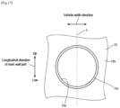
- FIG. 17 is a view in which a portion at which a through-hole is formed in a front wall part is seen from the inner side of a center pillar.
- FIG. 18 is a view for describing a modification of a center pillar.
- FIG. 19 is a view for describing another modification of a center pillar.
- FIG. 20 is a view for describing a further modification of a center pillar.
- FIG. 21 is a view for describing a further modification of a center pillar.
- FIG. 22 is a view for describing a further modification of a center pillar.
- FIG. 23 is a perspective view of an automobile structural member according to a second embodiment of the present invention.
- FIG. 24 is a schematic cross-sectional view of a portion corresponding to a line A-A in FIG. 23 .
- FIG. 25 is a view in which a portion at which a through-hole is formed in a vertical wall part is seen from the inner side of the automobile structural member.
- FIG. 26 is a view for describing a modification of the automobile structural member.
- FIG. 27 is a view for describing another modification of the automobile structural member.
- FIG. 28 is a view for describing a further modification of the automobile structural member.
- FIG. 29 is a perspective view illustrating an automobile structural member according to a third embodiment of the present invention.
- FIG. 30 is a perspective view illustrating an automobile structural member according to a fourth embodiment of the present invention.
- FIG. 31 is a schematic cross-sectional view of a portion corresponding to a line B-B in FIG. 30 .
- FIG. 32 is a schematic perspective view illustrating one part of a vehicle body.
- FIG. 33 is a schematic bottom view illustrating one part of a vehicle body.
- the present inventors conducted various studies in order to realize both an increase in strength and a reduction in weight of an automobile structural member in a compatible manner. As a result, the present inventors thought that, by performing burring on a cylindrical automobile structural member, the automobile structural member can be increased in strength and reduced in weight in a compatible manner. Therefore, the present inventors investigated the influence that burring has on the strength of an automobile structural member by numerical analysis (computer simulation) using a finite element method. Hereunder, the numerical analysis which the present inventors performed is described.
- FIG. 1 is a perspective view illustrating one example of an analysis model of an automobile structural member which uses numerical analysis.
- FIG. 2 is a cross-sectional view of the analysis model that shows a portion corresponding to a line II-II in FIG. 1 . Note that, in FIG. 1 and FIG. 2 , arrows indicating an X-direction, a Y-direction and a Z-direction which are orthogonal to each other are shown.
- an analysis model 100 has a polygonal cylindrical shape that extends in the X-direction, and has four wall parts 102 , 104 , 106 and 108 .
- the wall part 102 and the wall part 104 are provided so as to face each other in the Z-direction
- the wall part 106 and the wall part 108 are provided so as to face each other in the Y-direction.
- the analysis model 100 is formed by a steel sheet having a thickness of 0.8 mm and a tensile strength of 980 MPa-class.
- the length of the analysis model 100 in the X-direction is 1000 mm
- the length in the Y-direction and the Z-direction is 100 mm, respectively.
- the wall part 102 has a sheet-like main wall part 102 b in which a pair of through-holes 102 a are formed, and a pair of auxiliary wall parts 102 c which are provided for the pair of through-holes 102 a , respectively.
- the wall part 104 has a sheet-like main wall part 104 b in which a pair of through-holes 104 a are formed, and a pair of auxiliary wall parts 104 c which are provided for the pair of through-holes 104 a , respectively.
- each auxiliary wall part 102 c are formed by burring, and each auxiliary wall part 102 c has a circular cylindrical shape and is formed so as to rise from the edge of the through-hole 102 a toward the inner side of the analysis model 100 .
- the auxiliary wall parts 104 c are formed by burring, and each auxiliary wall part 104 c has a circular cylindrical shape and is formed so as to rise from the edge of the through-hole 104 a toward the inner side of the analysis model 100 .
- Each of the pair of through-holes 102 a is formed at the center in the Y-direction of the main wall part 102 b .
- each of the pair of through-holes 104 a is formed at the center in the Y-direction of the main wall part 104 b .
- the positions in the X-direction of the pair of through-holes 102 a and the positions in the X-direction of the pair of through-holes 104 a are equal to each other.
- An intermediate position in the X-direction between the pair of through-holes 102 a coincides with the center of the wall part 102 in the X-direction
- an intermediate position in the X-direction between the pair of through-holes 104 a coincides with the center of the wall part 104 in the X-direction.
- the diameter of each through-hole 102 a and each through-hole 104 a is 60 mm.
- a distance W (shortest distance between the edge of one through-hole 102 a and the edge of the other through-hole 102 a ) in the X-direction between the pair of through-holes 102 a is 80 mm.
- the distance in the X-direction between the pair of through-holes 104 a is 80 mm.
- the Y-direction is taken as the vertical direction. More specifically, the wall part 106 side in the Y-direction is taken as the upper side and the wall part 108 side in the Y-direction is taken as the lower side.
- three-point bending was performed by applying a load F to the wall part 106 in a state in which the wall part 108 was supported from underneath by a pair of support members 200 having an arc-shaped support surface.
- analysis models 100 a , 100 b and 100 c serving as comparison objects (hereunder, also referred to as comparison models 100 a , 100 b and 100 c ) that are illustrated in FIG. 3 , and investigated the relation between the amount of displacement in the downward direction of the pressing member and the load F.
- the comparison model 100 a has a similar structure to the aforementioned analysis model 100 except that the comparison model 100 a does not have the pair of through-holes 102 a , the pair of through-holes 104 a , the pair of auxiliary wall parts 102 c and the pair of auxiliary wall parts 104 c .
- the comparison model 100 b has a similar structure to the aforementioned analysis model 100 except that the comparison model 100 b does not have the pair of auxiliary wall parts 102 c and the pair of auxiliary wall parts 104 c .
- the comparison model 100 c has a similar structure to the aforementioned analysis model 100 except that in the comparison model 100 c the number of through-holes 102 a , through-holes 104 a , auxiliary wall parts 102 c and auxiliary wall parts 104 c is one, respectively. Note that, in the comparison model 100 c , the through-hole 102 a , the auxiliary wall part 102 c , the through-hole 104 a (not illustrated) and the auxiliary wall part 104 c (not illustrated) are provided at the center in the X-direction of the comparison model 100 c.
- FIG. 4 shows analysis results in a case where a height h of the auxiliary wall parts 102 c and 104 c (see FIG. 2 ) of the analysis model 100 was set to 7.2 mm, respectively, and a radius of curvature R of a portion indicated by a broken-line circle in FIG. 2 was set to 0 mm.
- the phrase “height h of the auxiliary wall parts 102 c and 104 c ” refers to the distance between the front end of the auxiliary wall parts 102 c and 104 c and the main wall parts 102 b and 104 b in the thickness direction of the main wall parts 102 b and 104 b , respectively.
- a case where the radius of curvature R of the portion indicated by the broken-line circle in FIG. 2 was set to 0 mm means a case where the internal surface of the main wall part 102 b and the outer peripheral surface of the auxiliary wall part 102 c intersect at a right angle and the internal surface of the main wall part 104 b and the outer peripheral surface of the auxiliary wall part 104 c intersect at a right angle.
- the analysis model 100 could receive a larger load than the comparison models 100 a , 100 b and 100 c .
- the analysis model 100 has excellent strength with respect to a load in the Y-direction.
- FIG. 5 is a view that schematically illustrates deformation behavior in a case where the analysis model 100 was caused to buckle. Note that, in FIG. 5 , the analysis model 100 before deformation is indicated by broken lines. Further, to avoid complicating the drawing, the through-holes and auxiliary wall parts are not illustrated in FIG. 5 .
- each of the wall parts 102 and 104 buckled so as to become convex toward the outer side at a center part in the Y-direction (vertical direction). In other words, buckling of the wall surface occurred.
- the present inventors also investigated what influence the height h (see FIG. 2 ) of the auxiliary wall parts 102 c and 104 c of the analysis model 100 has on the strength of the analysis model 100 .
- the present inventors set the height h of the auxiliary wall parts 102 c and 104 c to 3.0 mm, 4.0 mm and 7.2 mm, and performed numerical analysis under similar conditions as in the aforementioned analysis.
- the analysis results are shown in FIG. 6 .
- the analysis results for the comparison models 100 a and 100 b shown in FIG. 4 are also shown in FIG. 6 .
- the present inventors investigated the relation between the height h of the auxiliary wall parts 102 c and 104 c of the analysis model 100 and the maximum load in the Y-direction that the analysis model 100 can bear (maximum value of a load applied to the analysis model 100 when the aforementioned pressing member is moved 70 mm in the downward direction).
- the analysis model 100 having a thickness (sheet thickness of starting material) of 0.8 mm
- an analysis was also performed using the analysis model 100 having a thickness of 0.4 mm.
- the distance W in the X-direction between the pair of through-holes 102 a and the distance in the X-direction between the pair of through-holes 104 a was set to 60 mm.
- the height h of the auxiliary wall parts 102 c and 104 c was set to 2.8 mm, 3.0 mm, 4.0 mm and 7.2 mm. Further, for the analysis model 100 having a thickness of 0.4 mm, the height h of the auxiliary wall parts 102 c and 104 c was set to 2.8 mm, 3.0 mm, 3.2 mm, 3.4 mm and 7.6 mm. Note that, similar conditions to the conditions of the aforementioned analysis were adopted with respect to conditions other than these analysis conditions.
- FIG. 7 shows the analysis results for the analysis model 100 having a thickness of 0.8 mm
- FIG. 8 shows the analysis results for the analysis model 100 having a thickness of 0.4 mm.
- the maximum load ratio shown on the ordinate in FIG. 7 shows the ratio of the maximum load in the Y-direction that the analysis model 100 can bear with respect to the maximum load in the Y-direction that the comparison model 100 a (thickness of 0.8 mm) can bear (maximum value of a load applied to the comparison model 100 a when the aforementioned pressing member is moved 70 mm in the downward direction).
- the maximum load ratio shown on the ordinate in FIG. 8 shows the ratio of the maximum load in the Y-direction that the analysis model 100 can bear with respect to the maximum load in the Y-direction that the comparison model 100 a (thickness of 0.4 mm) can bear.
- the maximum load which the analysis model 100 can bear can be increased by raising the height h of the auxiliary wall parts 102 c and 104 c . Further, it was found that, regardless of the thickness of the analysis model 100 , by appropriately setting the height h of the auxiliary wall parts 102 c and 104 c , the maximum load which the analysis model 100 can bear can be increased in comparison to the maximum load which the comparison model 100 a (see FIG. 3 ) can bear.
- the present inventors also investigated what influence the relation between the width (length in the Y-direction) of the main wall parts 102 b and 102 c and the length in the Y-direction of the auxiliary wall parts 102 c and 104 c has on the strength of the analysis model 100 .
- the analysis model 100 having a thickness of 0.8 mm in which the height h of the auxiliary wall parts 102 c and 104 c was 7.2 mm was used, and analysis was performed under a condition in which a load was applied to the analysis model 100 in a similar manner to the aforementioned analysis.
- the length in the Y-direction of the auxiliary wall parts 102 c and 104 c was approximately equal to the diameter of the through-holes 102 a and 104 a .
- the ratio of the diameter of the through-holes 102 a and 104 a with respect to the width (length in the Y-direction) of the main wall parts 102 b and 104 b was varied, and the manner in which the maximum load in the Y-direction that the analysis model 100 could bear changed was investigated.
- the distance between the centers of the pair of through-holes 102 a in the X-direction and the distance between the centers of the pair of through-holes 104 a in the X-direction were each set to 140 mm.
- the maximum load ratio shown on the ordinate in FIG. 9 shows the ratio of the maximum load in the Y-direction which the analysis model 100 can bear with respect to the maximum load in the Y-direction which the comparison model 100 a (thickness of 0.8 mm) can bear.
- the maximum load which the analysis model 100 can bear can be increased in comparison to the maximum load which the comparison model 100 a (see FIG. 3 ) can bear. Note that, based on the results illustrated in FIG. 9 , it was found that the maximum load which the analysis model 100 can bear can be adequately increased by setting the ratio of the diameter of the through-holes 102 a and 104 a with respect to the width of the main wall parts 102 b and 104 b within the range of 0.3 or more to 1.0 or less.
- ratio of the length in the Y-direction of the auxiliary wall parts 102 c and 104 c with respect to the width of the main wall parts 102 b and 104 b (length in the Y-direction) within the range of 0.2 to 1.0, and more preferably within the range of 0.3 to 1.0.
- the present inventors also investigated the influence that the relation between the width of the main wall part (length in the Y-direction) and the distance between the auxiliary wall parts has on the strength of the analysis model 100 .
- the analysis model 100 having a thickness of 0.8 mm in which the height h of the auxiliary wall parts 102 c and 104 c was 7.2 mm, and the analysis model 100 having a thickness of 0.4 mm in which the height h of the auxiliary wall parts 102 c and 104 c was 7.2 mm were used, and analysis was performed under a condition in which a load was applied to each analysis model 100 in a similar manner to the aforementioned analysis.
- the distance between the pair of auxiliary wall parts 102 c was approximately equal to the distance W between the pair of through-holes 102 a
- the distance between the pair of auxiliary wall parts 104 c was approximately equal to the distance between the pair of through-holes 104 a
- the ratio of the distance between the pair of through-holes with respect to the width of the main wall part was varied, and the manner in which the maximum load in the Y-direction that the analysis model 100 could bear changed was investigated.
- the diameter of the through-holes 102 a and 104 a was set to 60 mm.
- the ratio of the distance between the pair of through-holes with respect to the width of the main wall part was set to 0.2, 0.4, 0.5, 0.6, 0.8, 1.0, 1.2, 1.4, 1.5 and 1.6.
- the ratio of the distance between the pair of through-holes with respect to the width of the main wall part was set to 0.2, 0.4, 0.6, 0.8, 1.0, 1.2, 1.4, 1.5 and 1.6.
- the analysis results for the analysis model 100 having a thickness of 0.8 mm are shown in FIG. 10
- the analysis results for the analysis model 100 having a thickness of 0.4 mm are shown in FIG. 11 .
- the maximum load ratio shown on the ordinate in FIG. 10 shows the ratio of the maximum load in the Y-direction which the analysis model 100 can bear with respect to the maximum load in the Y-direction which the comparison model 100 a (thickness 0.8 mm) can bear.
- the maximum load ratio shown on the ordinate in FIG. 11 shows the ratio of the maximum load in the Y-direction which the analysis model 100 can bear with respect to the maximum load in the Y-direction which the comparison model 100 a (thickness 0.4 mm) can bear.
- the ratio of the distance between the pair of through-holes with respect to the width of the main wall part is preferably set to 0.2 or more.
- the present inventors also investigated what influence the shape of a boundary part between the main wall part 102 b and the auxiliary wall part 102 c , and the shape of a boundary part between the main wall part 104 b and the auxiliary wall part 104 c have on the strength of the analysis model 100 .
- the radius of curvature R of the portion indicated by a broken-line circle in FIG. 2 was set to 0 mm, 1 mm and 2 mm, and analysis was performed using similar conditions as the analysis described above with regard to FIG. 4 .
- the analysis results are shown in FIG. 12 . Note that, for reference purposes, the analysis result for the comparison model 100 a shown in FIG. 4 are also shown in FIG. 12 .
- FIG. 13 (a) is a perspective view illustrating the analysis model 110
- (b) is a cross-sectional view of the analysis model 110 at a portion corresponding to a line b-b in (a).
- the analysis model 110 has a similar structure to the aforementioned analysis model 100 except that the analysis model 110 does not have the wall part 108 (see FIG. 1 ). Note that, the height h (see FIG.
- the comparison model 110 a has a similar structure to the aforementioned analysis model 110 except that the comparison model 110 a does not have the pair of through-holes 102 a , the pair of through-holes 104 a , the pair of auxiliary wall parts 102 c and the pair of auxiliary wall parts 104 c.
- the maximum load which the analysis model 110 can bear was 1.45 kN.
- the maximum load which the comparison model 110 a can bear was 1.25 kN.
- the present invention was made based on the findings described above.
- an automobile structural member has: a sheet-like first wall part; a sheet-like second wall part that faces the first wall part in a thickness direction of the first wall part; and a sheet-like third wall part that connects the first wall part and the second wall part.
- At least one of the first wall part and the second wall part has: a sheet-like main wall part in which a direction along a connecting part with the third wall part (extending direction of the connecting part) is the longitudinal direction, and in which at least two through-holes are formed so as to be aligned along the longitudinal direction; and at least two auxiliary wall parts which are provided so as to rise from the main wall part.
- One of the two auxiliary wall parts is provided so as to rise in the thickness direction of the main wall part from an edge of one of the two through-holes, and the other of the two auxiliary wall parts is provided so as to rise in the thickness direction of the main wall part from an edge of the other of the two through-holes.
- a distance between the two auxiliary wall parts in the longitudinal direction of the main wall part is 1.4 times or less the width of the main wall part at a portion between the two auxiliary wall parts.
- the shortest distance between two auxiliary wall parts is set to 1.4 times or less the width of the main wall part at a portion between the two auxiliary wall parts.
- each part of the automobile structural member is described using a vertical direction, a vehicle width direction and a front-and-rear direction with respect to a case where a state in which the automobile structural member is used as a constituent member of the vehicle body of an automobile while it is stopped on a horizontal plane is defined as a reference.
- the automobile structural member according to the embodiment of the present invention is formed using, for example, a starting material (sheet material) having a thickness within a range of 0.4 mm to 4.0 mm and a tensile strength of 980 MPa-class or more.
- a starting material sheet material
- a metal such as steel or aluminum, carbon fiber reinforced plastic (CFRP), or resin or the like can be used as the starting material of the automobile structural member.
- the present invention is preferably utilized for an automobile structural member that uses a starting material having a thickness within the range of 0.4 to 2.0 mm.
- the present invention is preferably utilized for an automobile structural member that uses a starting material having a tensile strength of 980 MPa or more, the present invention can also be utilized for an automobile structural member that uses a starting material having a tensile strength of less than 980 MPa.
- the tensile strength of a starting material can be measured by taking a tensile test specimen conforming to JIS Z 2201 from the starting material, and performing a tensile test in accordance with JIS Z 2241.
- An automobile structural member according to a first embodiment of the present invention is, when used as a constituent member of a vehicle body, a member in which a first wall part and a second wall part face each other in the front-and-rear direction. Further, the automobile structural member according to the first embodiment is, for example, when used as a constituent member of a vehicle body, a member in which a longitudinal direction of a main wall part to be described later is closer to the vertical direction than the vehicle width direction and the front-and-rear direction. Note that, the phrase “the longitudinal direction is closer to the vertical direction than the vehicle width direction and the front-and-rear direction” means that an angle (acute angle) formed by the longitudinal direction and the vertical direction is less than 45°.
- FIG. 15 is a perspective view illustrating the automobile structural member according to the first embodiment of the present invention.
- an automobile structural member 10 according to the present embodiment is a center pillar.
- the automobile structural member 10 according to the present embodiment is described as “center pillar 10 ”.
- FIG. 16 is a view illustrating a schematic cross-section (cross section perpendicular to the vertical direction) of a portion corresponding to a line A-A in FIG. 15 .
- the center pillar 10 is formed extending along the vertical direction and in a cylindrical shape.
- the center pillar 10 includes a sheet-like front wall part 12 , a sheet-like rear wall part 14 (see FIG. 16 ) that faces the front wall part 12 in the thickness direction of the front wall part 12 , a side wall part 16 that connects the front wall part 12 and the rear wall part 14 , and a side wall part 18 (see FIG. 16 ) that connects the front wall part 12 and the rear wall part 14 .
- the front wall part 12 and the rear wall part 14 face each other in the front-and-rear direction (front-and-rear direction of the vehicle body), and the side wall part 16 and the side wall part 18 face each other in the vehicle width direction.
- the front wall part 12 corresponds to the first wall part
- the rear wall part 14 corresponds to the second wall part
- the side wall part 16 corresponds to the third wall part.
- the front wall part 12 , the rear wall part 14 , the side wall part 16 and the side wall part 18 each have a long-length shape, and are formed so as to extend in the vertical direction.
- the side wall part 16 is formed so as to connect an edge part on one side (outer side) in the vehicle width direction of the front wall part 12 and an edge part on one side (outer side) in the vehicle width direction of the rear wall part 14 .
- the side wall part 18 is formed so as to connect an edge part on the other side (inner side) in the vehicle width direction of the front wall part 12 and an edge part on the other side (inner side) in the vehicle width direction of the rear wall part 14 .
- the center pillar 10 has a first member 10 a which has a hat-shaped cross-sectional shape, and a sheet-like second member 10 b .
- the first member 10 a is a center pillar outer
- the second member 10 b is a center pillar inner 10 b .
- the first member 10 a is described as a “center pillar outer 10 a ”
- the second member 10 b is described as a “center pillar inner 10 b ”.
- the center pillar outer 10 a and the center pillar inner 10 b are welded to each other.
- the center pillar outer 10 a has a hat-shaped cross-sectional shape, and has a pair of vertical wall parts (the front wall part 12 and the rear wall part 14 ), a top plate part (the side wall part 16 ), and a pair of flange parts 20 and 22 .
- the flange parts 20 and 22 and the center pillar inner 10 b are welded to each other.
- the front wall part 12 and the rear wall part 14 are connected through the flange parts 20 and 22 and the center pillar inner 10 b .
- the side wall part 18 that connects the front wall part 12 and the rear wall part 14 is formed by the flange parts 20 and 22 and the center pillar inner 10 b.
- the configuration of a center pillar to which the present invention can be applied is not limited to the configuration described above.
- the present invention can be applied to center pillars of various shapes that have a front wall part and a rear wall part which face each other in the front-and-rear direction of the vehicle body, and a pair of side wall parts which face each other in the vehicle width direction. Accordingly, a detailed description of the entire configuration of the center pillar 10 is omitted here.
- a state in which the internal surface of the first wall part faces the second wall part side, and the internal surface of the second wall part faces the first wall part side is defined as a state in which the first wall part and the second wall part face each other in the thickness direction of the first wall part.
- a state in which the internal surface of the front wall part faces rearward, and the internal surface of the rear wall part faces frontward is defined as a state in which the front wall part and the rear wall part face each other in the front-and-rear direction of the vehicle body. Accordingly, although the front wall part 12 and the rear wall part 14 illustrated in FIG. 16 are not parallel to each other, the front wall part 12 and the rear wall part 14 face each other in the front-and-rear direction of the vehicle body.
- a state in which the internal surface of a side wall part on one side in the vehicle width direction faces the other side in the vehicle width direction, and the internal surface of a side wall part on the other side in the vehicle width direction faces the one side in the vehicle width direction is defined as a state in which the pair of side wall parts face each other in the vehicle width direction.
- the front wall part 12 has a sheet-like main wall part 12 b in which a plurality of through-holes 12 a are formed, and a plurality of auxiliary wall parts 12 c which are provided for the plurality of through-holes 12 a , respectively.
- a direction along a connecting part 17 a between the main wall part 12 b and the side wall part 16 is the longitudinal direction of the main wall part 12 b .
- the plurality of through-holes 12 a are formed so as to be aligned along the longitudinal direction of the main wall part 12 b .
- four through-holes 12 a and four auxiliary wall parts 12 c are formed.
- the auxiliary wall part 12 c can be formed, for example, by a known burring method. The same applies with respect to an auxiliary wall part 14 c to be described later.
- the plurality of auxiliary wall parts 12 c are each provided so as to rise toward the rear wall part 14 side from the edge of the corresponding through-hole 12 a .
- the plurality of auxiliary wall parts 12 c are each provided so as to rise in the rearward direction.
- a distance H 1 between the front end of each auxiliary wall part 12 c and the main wall part 12 b is preferably 2.8 mm or more, more preferably is 3.0 mm or more, and further preferably is 4.0 mm or more.
- the rear wall part 14 has a sheet-like main wall part 14 b in which a plurality of through-holes 14 a (in FIG. 16 , only one through-hole 14 a is illustrated) are formed, and a plurality of auxiliary wall parts 14 c provided for the plurality of through-holes 14 a , respectively.
- a direction along a connecting part 17 b between the main wall part 14 b and the side wall part 16 is the longitudinal direction of the main wall part 14 b .
- the plurality of through-holes 14 a are formed so as to be aligned along the longitudinal direction of the main wall part 14 b .
- four through-holes 14 a and four auxiliary wall parts 14 c are formed.
- the plurality of auxiliary wall parts 14 c are each provided so as to rise toward the front wall part 12 side from the edge of the corresponding through-hole 14 a .
- the plurality of auxiliary wall parts 14 c are each provided so as to rise in the frontward direction.
- a distance H 2 between the front end of each auxiliary wall part 14 c and the main wall part 14 b is preferably 2.8 mm or more, more preferably is 3.0 mm or more, and further preferably is 4.0 mm or more.
- a direction perpendicular to the longitudinal direction of the main wall part 12 b (direction perpendicular to the extending direction of the connecting part 17 a ) is taken as the width direction of the main wall part 12 b .
- the width (length in the width direction) of the main wall part 12 b is, for example, set within a range of 50 mm to 200 mm.
- a direction perpendicular to the longitudinal direction of the main wall part 14 b (direction perpendicular to the extending direction of the connecting part 17 b ) is taken as the width direction of the main wall part 14 b .
- the width (length in the width direction) of the main wall part 14 b is, for example, set within a range of 50 mm to 200 mm.
- the distance (distance in the longitudinal direction of the main wall part 12 b ) between two auxiliary wall parts 12 c that are adjacent is set so as to be 1.4 times or less the width of the main wall part 12 b at the portion between the relevant two auxiliary wall parts 12 c .
- the distance (distance in the longitudinal direction of the main wall part 14 b ) between two auxiliary wall parts 14 c that are adjacent is set so as to be 1.4 times or less the width of the main wall part 14 b at the portion between the relevant two auxiliary wall parts 14 c .
- the shortest distance between two auxiliary wall parts 12 c is set so as to be 1.4 times or less the width of the main wall part 12 b at the portion between the two auxiliary wall parts 12 c
- the shortest distance between two auxiliary wall parts 14 c is set so as to be 1.4 times or less the width of the main wall part 14 b at the portion between the two auxiliary wall parts 14 c.
- the distance between two auxiliary wall parts is determined by taking the base (boundary part with respect to the main wall part) of the respective auxiliary wall parts as a reference. Accordingly, as illustrated in FIG. 18 to be described later, even in a case where auxiliary wall parts incline with respect to the main wall part, the phrase “distance between two auxiliary wall parts” means the distance between the bases of the two auxiliary wall parts, and not the distance between the front ends of the two auxiliary wall parts.
- the distance between two through-holes 12 a that are adjacent is also similarly set so as to be 1.4 times or less the width of the main wall part 12 b at the portion between the relevant two through-holes 12 a .
- the distance between two through-holes 14 a that are adjacent is also similarly set so as to be 1.4 times or less the width of the main wall part 14 b at the portion between the relevant two through-holes 14 a.
- the distance in the aforementioned longitudinal direction between two auxiliary wall parts 12 c that are adjacent is preferably set so as to be 0.2 times or more the width of the main wall part 12 b at a portion between the relevant two auxiliary wall parts 12 c , and more preferably is set so as to be 0.4 times or more the aforementioned width, and further preferably is set so as to be 0.6 times or more the aforementioned width.
- the distance in the aforementioned longitudinal direction between two auxiliary wall parts 14 c that are adjacent is also preferably set so as to be 0.2 times or more the width of the main wall part 14 b at a portion between the relevant two auxiliary wall parts 14 c , and more preferably is set so as to be 0.4 times or more the aforementioned width, and further preferably is set so as to be 0.6 times or more the aforementioned width.
- the distance in the aforementioned longitudinal direction between two through-holes 12 a that are adjacent is preferably set so as to be 0.2 times or more the width of the main wall part 12 b at a portion between the relevant two through-holes 12 a , and more preferably is set so as to be 0.4 times or more the aforementioned width, and further preferably is set so as to be 0.6 times or more the aforementioned width.
- the distance in the aforementioned longitudinal direction between two through-holes 14 a that are adjacent is also preferably set so as to be 0.2 times or more the width of the main wall part 14 b at a portion between the relevant two through-holes 14 a , and more preferably is set so as to be 0.4 times or more the aforementioned width, and further preferably is set so as to be 0.6 times or more the aforementioned width.
- width of a main wall part at a portion between two auxiliary wall parts (through-holes) is not constant, the phrase “width of the main wall part at a portion between the two auxiliary wall parts (through-holes)” means the largest value of the width of the main wall part at the portion between the two auxiliary wall parts (through-holes).
- the distance between two auxiliary wall parts (through-holes) that are adjacent may be set so as to be 1.4 times or less the smallest value of the width of the main wall part at the portion between the relevant two auxiliary wall parts (through-holes), or may be set so as to be 0.2 times or more the smallest value of the width of the main wall part at the portion between the relevant two auxiliary wall parts (through-holes).
- the plurality of auxiliary wall parts 12 c and the plurality of auxiliary wall parts 14 c are provided at positions that are lower than the center of the center pillar 10 in the vertical direction.
- the number of the through-holes 12 a and the auxiliary wall parts 12 c is not limited to four, respectively, and may be two or three, or may be five or more. The same applies with respect to the through-holes 14 a and the auxiliary wall parts 14 c.
- FIG. 17 is a view illustrating a portion at which the through-hole 12 a is formed in the front wall part 12 as seen from the inner side of the center pillar 10 .
- an imaginary straight line L which, as seen from the thickness direction of the main wall part 12 b , passes through the center of the through-hole 12 a and is parallel to the longitudinal direction of the main wall part 12 b is indicated by a dashed line.
- the auxiliary wall part 12 c is provided so as to intersect with the straight line L on one side and the other side of the through-hole 12 a in the longitudinal direction of the main wall part 12 b .
- each through-hole 12 a has a circular shape
- each auxiliary wall part 12 c has a cylindrical shape (in the present embodiment, a circular cylindrical shape).
- each through-hole 14 a has a circular shape
- each auxiliary wall part 14 c has a cylindrical shape (in the present embodiment, a circular cylindrical shape).
- the length of the auxiliary wall part 12 c in the width direction of the main wall part 12 b is preferably 0.2 times or more the width of the main wall part 12 b at a cross section which passes through the center of the through-hole 12 a corresponding to the relevant auxiliary wall part 12 c and which is perpendicular to the longitudinal direction of the main wall part 12 b , and more preferably is 0.3 times or more the width of the main wall part 12 b at the aforementioned cross section.
- the length of the auxiliary wall part 12 c in the width direction of the main wall part 12 b is preferably 1.0 times or less the width of the main wall part 12 b at a cross section which passes through the center of the through-hole 12 a corresponding to the relevant auxiliary wall part 12 c and which is perpendicular to the longitudinal direction of the main wall part 12 b , and more preferably is 0.9 times or less the width of the main wall part 12 b at the aforementioned cross section.
- the length of the auxiliary wall part 14 c in the width direction of the main wall part 14 b is preferably 0.2 times or more the width of the main wall part 14 b at a cross section which passes through the center of the through-hole 14 a corresponding to the relevant auxiliary wall part 14 c and which is perpendicular to the longitudinal direction of the main wall part 14 b , and more preferably is 0.3 times or more the width of the main wall part 14 b at the aforementioned cross section.
- the length of the auxiliary wall part 14 c in the width direction of the main wall part 14 b is preferably 1.0 times or less the width of the main wall part 14 b at a cross section which passes through the center of the through-hole 14 a corresponding to the relevant auxiliary wall part 14 c and which is perpendicular to the longitudinal direction of the main wall part 14 b , and more preferably is 0.9 times or less the width of the main wall part 14 b at the aforementioned cross section.
- the respective lengths of the through-hole 12 a and the auxiliary wall part 12 c in the width direction of the main wall part 12 b are set to, for example, a size that is 0.4 to 0.7 times the width of the main wall part 12 b .
- the respective lengths of the through-hole 14 a and the auxiliary wall part 14 c in the width direction of the main wall part 14 b are set to, for example, a size that is 0.4 to 0.7 times the width of the main wall part 14 b.
- the respective lengths of the through-holes 12 a and 14 a and the auxiliary wall parts 12 c and 14 c are set to, for example, 0.4 times or more the respective widths of the corresponding main wall parts 12 b and 14 b .
- the length of the through-holes 12 a and 14 a is too large, the regions which receive a load in the main wall parts 12 b and 14 b will be reduced, and there is a risk that the buckling suppression effect will decrease.
- the respective lengths of the through-holes 12 a and 14 a and of the auxiliary wall parts 12 c and 14 c are set to, for example, 0.7 times or less the respective widths of the corresponding main wall parts 12 b and 14 b.
- a plurality of the auxiliary wall parts 12 c are formed in the front wall part 12
- a plurality of the auxiliary wall parts 14 c are formed in the rear wall part 14 .
- the center pillar 10 (automobile structural member) which is light in weight and which has excellent strength with respect to a side impact is obtained.
- the plurality of auxiliary wall parts 12 c and the plurality of auxiliary wall parts 14 c are provided at positions that are lower than the center of the center pillar 10 in the vertical direction.
- the auxiliary wall part 12 c may incline with respect to the main wall part 12 b .
- the distance H 1 between the front end of the auxiliary wall part 12 c and the main wall part 12 b is preferably 2.8 mm or more, more preferably is 3.0 mm or more, and further preferably is 4.0 mm or more.
- the distance H 2 between the front end of the auxiliary wall part 14 c and the main wall part 14 b is preferably 2.8 mm or more, more preferably is 3.0 mm or more, and further preferably is 4.0 mm or more.
- the auxiliary wall part 12 c may be formed so that the diameter increases progressively toward the front end side. The same applies with respect to the auxiliary wall part 14 c.
- the angle ⁇ 1 that the main wall part 12 b and the auxiliary wall part 12 c form is preferably set within the range of 50 to 130°, more preferably is set within the range of 70 to 110°, and further preferably is set within the range of 80 to 100°.
- an angle ⁇ 2 that the main wall part 14 b and the auxiliary wall part 14 c form is preferably set within the range of 50 to 130°, more preferably is set within the range of 70 to 110°, and further preferably is set within the range of 80 to 100°.
- the phrase “angle that the main wall part and the auxiliary wall part form” means an angle that the main wall part and the auxiliary wall part form at a cross section that passes through the center of the through-hole and perpendicular to the longitudinal direction of the main wall part.
- the angle ⁇ 1 in the present embodiment is an angle that the main wall part 12 b and the auxiliary wall part 12 c form at a cross section that passes through the center of the through-hole 12 a and perpendicular to the longitudinal direction of the main wall part 12 b .
- the angle ⁇ 2 in the present embodiment is an angle that the main wall part 14 b and the auxiliary wall part 14 c form at a cross section that passes through the center of the through-hole 14 a and perpendicular to the longitudinal direction of the main wall part 14 b.
- the shapes of the through-hole 12 a and the auxiliary wall part 12 c are not limited to the shapes described in the aforementioned example.
- the through-hole 12 a may have a polygonal shape (in FIG. 19 , a rectangular shape), and the auxiliary wall part 12 c may have a polygonal cylindrical shape.
- a detailed description is omitted here, the same also applies with respect to the through-hole 14 a and the auxiliary wall part 14 c.
- the shape of the auxiliary wall parts 12 c and 14 c is not limited to a cylindrical shape.
- each of the auxiliary wall parts is preferably provided so that, as seen from the thickness direction of the main wall part, on one side and the other side of the corresponding through-hole in the longitudinal direction of the main wall part, the auxiliary wall part intersects with a straight line (imaginary line) that passes through the center of the through-hole and is parallel to the longitudinal direction of the main wall part.
- the auxiliary wall part 12 c is formed so as to extend in the vehicle width direction at least at the upper end and lower end of the through-hole 12 a .
- the auxiliary wall part 12 c may be composed of a plurality of walls 12 d and 12 e that are formed so as to be spaced apart from each other in the circumferential direction of the through-hole 12 a.
- the wall 12 d is provided on one side of the through-hole 12 a in the longitudinal direction of the main wall part 12 b
- the wall 12 e is provided on the other side of the through-hole 12 a in the aforementioned longitudinal direction.
- the walls 12 d and 12 e are each provided so that, as seen from the thickness direction of the main wall part 12 b , the walls 12 d and 12 e each intersect with a straight line L that passes through the center of the through-hole 12 a and is parallel to the longitudinal direction of the main wall part 12 b .
- the wall 12 d is formed along the edge of the through-hole 12 a so as to extend in the vehicle width direction along the upper end of the through-hole 12 a
- the wall 12 e is formed along the edge of the through-hole 12 a so as to extend in the vehicle width direction along the lower end of the through-hole 12 a
- an angle that the wall 12 d and the main wall part 12 b form, and an angle that the wall 12 e and the main wall part 12 b form are each preferably set within the range of 50 to 130°, more preferably are each set within the range of 70 to 110°, and further preferably are each set within the range of 80 to 100°.
- the auxiliary wall part 14 c may also be composed of a plurality of walls, similarly to the auxiliary wall part 12 c .
- the length of each of the walls in the width direction of the main wall part is preferably within the range of 0.2 times or more to 1.0 times or less the width of the main wall part at a cross section which passes through the center of the through-hole corresponding to the relevant wall and which is perpendicular to the longitudinal direction of the main wall part, and more preferably is within the range of 0.3 times or more to 0.9 times or less the width of the main wall part at the aforementioned cross section.
- each of the walls in the width direction of the main wall part is, for example, set to a size that is within the range of 0.4 to 0.7 times the width of the main wall part at a cross section which passes through the center of the through-hole corresponding to the relevant wall and which is perpendicular to the longitudinal direction of the main wall part. The same also applies with respect to embodiments that are described later.
- the auxiliary wall part 12 c may be composed of a plurality of walls.
- two walls among the plurality of walls are provided so as to intersect with a straight line L which passes through the center of the through-hole 12 a and which is parallel to the longitudinal direction of the main wall part 12 b .
- the auxiliary wall part 14 c may be similarly composed of a plurality of walls.
- the auxiliary wall part 12 c may be formed so as to rise from the edge of the through-hole 12 a toward the opposite side to the rear wall part 14 .
- the auxiliary wall part 12 c may be formed so as to rise in the frontward direction from the edge of the through-hole 12 a .
- the auxiliary wall part 14 c may be formed so as to rise toward the opposite side to the front wall part 12 from the edge of the through-hole 14 a .
- the auxiliary wall part 14 c may be formed so as to rise in the rearward direction from the edge of the through-hole 14 a .
- an auxiliary wall part may be provided so as to project toward the inner side of the automobile structural member or may be provided so as to project toward the outer side of the automobile structural member.
- the plurality of through-holes 12 a are formed so as to be aligned in a row along the longitudinal direction of the main wall part 12 b (in the present embodiment, the vertical direction) as seen from the front of the vehicle
- the plurality of through-holes 12 a may be arranged so as to be aligned in a staggered manner along the longitudinal direction of the main wall part 12 b .
- the same also applies with respect to the plurality of through-holes 14 a.
- a plurality of through-holes and a plurality of auxiliary wall parts are provided in each of the front wall part and the rear wall part, for example, the plurality of through-holes and the plurality of auxiliary wall parts need not be provided in the rear wall part 14 , as in the case of a center pillar 10 illustrated in FIG. 21 . Further, the plurality of through-holes and the plurality of auxiliary wall parts need not be provided in the front wall part 12 , as in the case of a center pillar 10 illustrated in FIG. 22 .
- the plurality of through-holes and the plurality of auxiliary wall parts are provided in at least one of the front wall part and the rear wall part. Even in such a case, the advantageous effect of improving the strength of the front wall part or the rear wall part by means of the auxiliary wall parts is obtained, and the absorbed amount of collision energy can be increased. Note that, in a case where the plurality of through-holes and the plurality of auxiliary wall parts are provided in both the front wall part and the rear wall part, the advantageous effect of absorbing collision energy can be further enhanced since deformation modes with respect to a load can be made uniform between the front wall part and the rear wall part.
- the present invention is applied to a cylindrical automobile structural member (center pillar) having a front wall part, a rear wall part and a pair of side wall parts
- the number of side wall parts may be one.
- the present invention can be applied to an automobile structural member having a front wall part and a rear wall part that face each other in the front-and-rear direction of the vehicle, and a side wall part that connects the front wall part and the rear wall part.
- the present invention can also be applied to an automobile structural member having a cross-sectional U shape, as illustrated in FIG. 13 .
- the front wall part, the rear wall part and the side wall part may be formed so as to extend in the vehicle width direction.
- the side wall part may be formed so as to connect an upper edge part of the front wall part and an upper edge part of the rear wall part, or may be formed so as to connect a lower edge part of the front wall part and a lower edge part of the rear wall part.
- An automobile structural member according to a second embodiment of the present invention is a member in which, when used as a constituent member of a vehicle body, a first wall part and a second wall part face each other in the vertical direction. Further, the automobile structural member according to the second embodiment is, for example, when used as a constituent member of a vehicle body, a member in which the longitudinal direction of a main wall part to be described later is closer to the vehicle width direction or the front-and-rear direction than the vertical direction. The same also applies with respect to an automobile structural member according to a third embodiment and a fourth embodiment to be described later.
- the phrase “the longitudinal direction is closer to the vehicle width direction or the front-and-rear direction than the vertical direction” means that an angle (acute angle) formed by the longitudinal direction and the vehicle width direction or an angle (acute angle) formed by the longitudinal direction and the front-and-rear direction is less than 45°.
- FIG. 23 is a perspective view illustrating the automobile structural member according to the second embodiment of the present invention. Note that, in FIG. 23 , arrows are shown which indicate the vertical direction, a first direction and a second direction which are orthogonal to each other.
- FIG. 24 is a view illustrating a schematic cross-section (cross section perpendicular to the first direction) of a portion corresponding to a line A-A in FIG. 23 .
- an automobile structural member 10 (hereinafter, abbreviated to a “structural member 10 ”) according to the present embodiment is formed so as to extend in a first direction perpendicular to the vertical direction and is formed in a cylindrical shape.
- the structural member 10 includes a sheet-like vertical wall part 12 , a sheet-like vertical wall part 14 that faces the vertical wall part 12 in the thickness direction of the vertical wall part 12 , and a top plate part 16 that connects the vertical wall part 12 and the vertical wall part 14 .
- the vertical wall part 12 corresponds to a first wall part
- the vertical wall part 14 corresponds to a second wall part
- the top plate part 16 corresponds to a third wall part.
- the phrase “member that extends in the first direction” means a member, the longitudinal direction of which coincides with the first direction in plan view and is closer to the first direction than the vertical direction as seen from the second direction.
- the phrase “member that extends in the first direction” means a member, the longitudinal direction of which coincides with the first direction in plan view and an angle (acute angle) formed by the longitudinal direction and the first direction is less than 45° as seen from the second direction. Accordingly, a member that extends in the first direction is not limited to a member, the longitudinal direction of which coincides with the first direction as seen from the second direction.
- the structural member 10 has a first member 10 a which has a hat-shaped cross-sectional shape, and a sheet-like second member 10 b .
- the first member 10 a has the pair of vertical wall parts 12 and 14 , the top plate part 16 , and a pair of flange parts 18 and 20 .
- the respective parts of the first member 10 a vertical wall parts 12 and 14 , top plate part 16 and flange parts 18 and 20
- the second member 10 b each have a long-length shape, and are formed so as to extend in the first direction.
- the vertical wall part 12 and the vertical wall part 14 are provided so as to face each other in the vertical direction.
- the top plate part 16 is provided so as to connect an edge part on one side in the second direction of the vertical wall part 12 and an edge part on one side in the second direction of the vertical wall part 14 .
- the flange part 18 is provided so as to extend upward from an edge part of the vertical wall part 12 which is an edge part on the opposite side to the top plate part 16 in the second direction
- the flange part 20 is provided so as to extend downward from an edge part of the vertical wall part 14 which is an edge part on the opposite side to the top plate part 16 in the second direction.
- the flange parts 18 and 20 and the second member 10 b are welded to each other.
- the second member 10 b is connected to the vertical wall part 12 and the vertical wall part 14 through the flange parts 18 and 20 .
- the second member 10 b is provided so as to face the top plate part 16 in the second direction.
- the vertical wall part 12 functions as an upper wall part of the structural member 10
- the vertical wall part 14 functions as a lower wall part of the structural member 10
- the top plate part 16 functions as a side wall part which connects an edge part on one side in the second direction of the vertical wall part 12 and an edge part on one side in the second direction of the vertical wall part 14
- the flange parts 18 and 20 and the second member 10 b function as a side wall part 22 which connects an edge part on the other side in the second direction of the vertical wall part 12 and an edge part on the other side in the second direction of the vertical wall part 14 .
- a state in which the internal surface of the upper wall part is facing downward and the internal surface of the lower wall part is facing upward is defined as a state in which the upper wall part and the lower wall part are facing each other in the vertical direction. Accordingly, although the vertical wall part 12 (upper wall part) and the vertical wall part 14 (lower wall part) illustrated in FIG. 23 and FIG. 24 are not parallel to each other, they are facing each other in the vertical direction.
- a state in which the internal surface of a side wall part on one side in the second direction faces the other side in the second direction, and the internal surface of a side wall part on the other side in the second direction faces the one side in the second direction is defined as a state in which the pair of side wall parts face each other in the second direction.
- the vertical wall part 12 has a sheet-like main wall part 12 b in which a plurality of through-holes 12 a are formed, and a plurality of auxiliary wall parts 12 c which are provided for the plurality of through-holes 12 a , respectively.
- a direction along a connecting part 17 a between the main wall part 12 b and the top plate part 16 is the longitudinal direction of the main wall part 12 b .
- the plurality of through-holes 12 a are formed so as to be aligned along the longitudinal direction of the main wall part 12 b .
- the plurality of through-holes 12 a are formed so as to be aligned along the first direction.
- auxiliary wall part 12 c can be formed, for example, by a known burring method. The same applies with respect to an auxiliary wall part 14 c to be described later.
- the plurality of auxiliary wall parts 12 c are each provided so as to rise toward the vertical wall part 14 side from the edge of the corresponding through-hole 12 a .
- the plurality of auxiliary wall parts 12 c are each provided so as to rise in the downward direction.
- a distance H 1 between the front end of each auxiliary wall part 12 c and the main wall part 12 b is preferably 2.8 mm or more, more preferably is 3.0 mm or more, and further preferably is 4.0 mm or more.
- the vertical wall part 14 has a sheet-like main wall part 14 b in which a plurality of through-holes 14 a are formed, and a plurality of auxiliary wall parts 14 c which are provided for the plurality of through-holes 14 a , respectively.
- a direction along a connecting part 17 b between the main wall part 14 b and the top plate part 16 is the longitudinal direction of the main wall part 14 b .
- the plurality of through-holes 14 a are formed so as to be aligned along the longitudinal direction of the main wall part 14 b .
- the plurality of through-holes 14 a are formed so as to be aligned in the first direction, similarly to the plurality of through-holes 12 a.
- the plurality of auxiliary wall parts 14 c are each provided so as to rise toward the vertical wall part 12 side from the edge of the corresponding through-hole 14 a .
- the plurality of auxiliary wall parts 14 c are each provided so as to rise in the upward direction.
- a distance H 2 between the front end of each auxiliary wall part 14 c and the main wall part 14 b is preferably 2.8 mm or more, more preferably is 3.0 mm or more, and further preferably is 4.0 mm or more.
- a direction perpendicular to the longitudinal direction of the main wall part 12 b (direction perpendicular to the extending direction of the connecting part 17 a ) is taken as the width direction of the main wall part 12 b .
- the width (length in the width direction) of the main wall part 12 b is, for example, set within a range of 50 mm to 200 mm.
- a direction perpendicular to the longitudinal direction of the main wall part 14 b (direction perpendicular to the extending direction of the connecting part 17 b ) is taken as the width direction of the main wall part 14 b .
- the width (length in the width direction) of the main wall part 14 b is, for example, set within a range of 50 mm to 200 mm.
- the distance (distance in the longitudinal direction of the main wall part 12 b ) between two auxiliary wall parts 12 c that are adjacent is set so as to be 1.4 times or less the width of the main wall part 12 b at the portion between the relevant two auxiliary wall parts 12 c .
- the distance (distance in the longitudinal direction of the main wall part 14 b ) between two auxiliary wall parts 14 c that are adjacent is set so as to be 1.4 times or less the width of the main wall part 14 b at the portion between the relevant two auxiliary wall parts 14 c .
- the shortest distance between two auxiliary wall parts 12 c is set so as to be 1.4 times or less the width of the main wall part 12 b at the portion between the two auxiliary wall parts 12 c
- the shortest distance between two auxiliary wall parts 14 c is set so as to be 1.4 times or less the width of the main wall part 14 b at the portion between the two auxiliary wall parts 14 c.
- the distance between two auxiliary wall parts is determined by taking the base (boundary part with respect to the main wall part) of the respective auxiliary wall parts as a reference. Accordingly, as illustrated in FIG. 26 which is described later, even in a case where auxiliary wall parts incline with respect to the main wall part, the phrase “distance between two auxiliary wall parts” means the distance between the bases of the two auxiliary wall parts, and not the distance between the front ends of the two auxiliary wall parts.
- the distance between two through-holes 12 a that are adjacent is set so as to be 1.4 times or less the width of the main wall part 12 b at the portion between the relevant two through-holes 12 a .
- the distance between two through-holes 14 a that are adjacent is also similarly set so as to be 1.4 times or less the width of the main wall part 14 b at the portion between the relevant two through-holes 14 a.
- the distance in the aforementioned longitudinal direction between two auxiliary wall parts 12 c that are adjacent is preferably set so as to be 0.2 times or more the width of the main wall part 12 b at the portion between the relevant two auxiliary wall parts 12 c , and more preferably is set so as to be 0.4 times or more the aforementioned width, and further preferably is set so as to be 0.6 times or more the aforementioned width.
- the distance in the aforementioned longitudinal direction between two auxiliary wall parts 14 c that are adjacent is also preferably set so as to be 0.2 times or more the width of the main wall part 14 b at the portion between the relevant two auxiliary wall parts 14 c , and more preferably is set so as to be 0.4 times or more the aforementioned width, and further preferably is set so as to be 0.6 times or more the aforementioned width.
- the distance in the aforementioned longitudinal direction between two through-holes 12 a that are adjacent is preferably set so as to be 0.2 times or more the width of the main wall part 12 b at the portion between the relevant two through-holes 12 a , and more preferably is set so as to be 0.4 times or more the aforementioned width, and further preferably is set so as to be 0.6 times or more the aforementioned width.
- the distance in the aforementioned longitudinal direction between two through-holes 14 a that are adjacent is also preferably set so as to be 0.2 times or more the width of the main wall part 14 b at the portion between the relevant two through-holes 14 a , and more preferably is set so as to be 0.4 times or more the aforementioned width, and further preferably is set so as to be 0.6 times or more the aforementioned width.
- the phrase “width of the main wall part at the portion between the two auxiliary wall parts (through-holes)” means the largest value of the width of the main wall part at the portion between the two auxiliary wall parts (through-holes).
- the distance between two auxiliary wall parts (through-holes) that are adjacent may be set so as to be 1.4 times or less the smallest value of the width of the main wall part at the portion between the relevant two auxiliary wall parts (through-holes), or may be set so as to be 0.2 times or more the smallest value of the width of the main wall part at the portion between the relevant two auxiliary wall parts (through-holes).
- the number of the through-holes 12 a and the auxiliary wall parts 12 c is not limited to two, respectively, and may be three or more. The same applies with respect to the through-holes 14 a and the auxiliary wall parts 14 c.
- FIG. 25 is a view illustrating a portion at which the through-hole 12 a is formed in the vertical wall part 12 as seen from the inner side of the structural member 10 .
- an imaginary straight line L that, as seen from the thickness direction of the main wall part 12 b , passes through the center of the through-hole 12 a and is parallel to the longitudinal direction of the main wall part 12 b is indicated by a dashed line.
- the auxiliary wall part 12 c is provided so as to intersect with the straight line L on one side and the other side of the through-hole 12 a in the longitudinal direction of the main wall part 12 b .
- each through-hole 12 a has a circular shape
- each auxiliary wall part 12 c has a cylindrical shape (in the present embodiment, a circular cylindrical shape).
- each through-hole 14 a has a circular shape
- each auxiliary wall part 14 c has a cylindrical shape (in the present embodiment, a circular cylindrical shape).
- the respective lengths of the auxiliary wall parts 12 c and 14 c in the width direction of the corresponding main wall part 12 b or 14 b are each preferably 0.2 times or more the width of the corresponding main wall part 12 b or 14 b , and more preferably 0.3 times or more. Further, the respective lengths of the auxiliary wall parts 12 c and 14 c in the width direction of the corresponding main wall part 12 b or 14 b are each preferably 1.0 times or less the width of the corresponding main wall part 12 b or 14 b , and more preferably 0.9 times or less.
- the respective lengths of the through-hole 12 a and the auxiliary wall part 12 c in the width direction of the main wall part 12 b are set to, for example, a size that is 0.4 to 0.7 times the width of the main wall part 12 b .
- the respective lengths of the through-hole 14 a and the auxiliary wall part 14 c in the width direction of the main wall part 14 b are set to, for example, a size that is 0.4 to 0.7 times the width of the main wall part 14 b.
- a plurality of the auxiliary wall parts 12 c are formed in the vertical wall part 12
- a plurality of the auxiliary wall parts 14 c are formed in the vertical wall part 14 .
- the weight of the structural member 10 can be reduced.
- the automobile structural member 10 which is light in weight and which has excellent strength with respect to a collision is obtained.
- the auxiliary wall part 12 c may incline with respect to the main wall part 12 b .
- the distance H 1 between the front end of the auxiliary wall part 12 c and the main wall part 12 b is preferably 2.8 mm or more, more preferably is 3.0 mm or more, and further preferably is 4.0 mm or more.
- the distance H 2 between the front end of the auxiliary wall part 14 c and the main wall part 14 b is preferably 2.8 mm or more, more preferably is 3.0 mm or more, and further preferably is 4.0 mm or more.
- the auxiliary wall part 12 c may be formed so that the diameter increases progressively toward the front end side. The same applies with respect to the auxiliary wall part 14 c.
- an angle that the main wall part and the auxiliary wall part form is preferably set within the range of 50 to 130°, more preferably is set within the range of 70 to 110°, and further preferably is set within the range of 80 to 100°.
- the through-hole 12 a may have a polygonal shape (in FIG. 27 , a rectangular shape), and the auxiliary wall part 12 c may have a polygonal cylindrical shape.
- the through-hole 14 a and the auxiliary wall part 14 c may have a polygonal cylindrical shape.
- the auxiliary wall part 12 c may be composed of a plurality of walls 12 d and 12 e that are formed so as to be spaced apart from each other in the circumferential direction of the through-hole 12 a .
- each of the auxiliary wall parts is preferably provided so that, as seen from the thickness direction of the main wall part, on one side and the other side of the corresponding through-hole in the longitudinal direction of the main wall part, the auxiliary wall part intersects with a straight line (imaginary line) that passes through the center of the through-hole and is parallel to the longitudinal direction of the main wall part. Note that, in the example illustrated in FIG.
- the wall 12 d is formed along the edge of the through-hole 12 a so as to extend in the second direction along one end in the first direction of the through-hole 12 a
- the wall 12 e is formed along the edge of the through-hole 12 a so as to extend in the second direction along the other end in the first direction of the through-hole 12 a.
- the auxiliary wall part 12 c may be composed of a plurality of walls.
- two walls among the plurality of walls are provided so as to intersect with a straight line L which passes through the center of the through-hole 12 a and is parallel to the longitudinal direction of the main wall part 12 b .
- the auxiliary wall part 14 c may be similarly composed of a plurality of walls.
- auxiliary wall parts may be provided so as to project toward the inner side of the automobile structural member or may be provided so as to project toward the outer side of the automobile structural member.
- the plurality of through-holes may be arranged in a staggered manner.
- the present invention can be applied to various kinds of automobile structural members having an upper wall part and a lower wall part that face each other in the vertical direction and that extend in the first direction, and having a side wall part that connects the upper wall part and the lower wall part.
- the structural member 10 need not have the second member 10 b.
- top plate part 16 and the side wall part 22 are arranged parallel to the vertical direction, the top plate part 16 and the side wall part 22 may be inclined with respect to the vertical direction.
- FIG. 29 is a perspective view that illustrates an automobile structural member according to a third embodiment of the present invention.
- an automobile structural member 30 according to the present embodiment (hereinafter, abbreviated to a “structural member 30 ”) is formed so as to extend in the first direction and is formed in a cylindrical shape, similarly to the structural member 10 illustrated in FIG. 23 .
- the structural member 30 according to the present embodiment differs from the structural member 10 illustrated in FIG. 23 in that the structural member 30 includes a second member 10 c instead of the second member 10 b.
- the second member 10 c has a hat-shaped cross-sectional shape, and has a pair of vertical wall parts 32 and 34 , a top plate part 36 and flange parts 38 and 40 .
- Each part (vertical wall parts 32 and 34 , top plate part 36 and flange parts 38 and 40 ) of the second member 10 c has a long-length shape, and is formed to extend in the first direction.
- the vertical wall part 32 and the vertical wall part 34 are provided so as to face each other in the vertical direction.
- the top plate part 36 is provided so as to connect an edge part of the vertical wall part 32 that is the edge part on the opposite side to the first member 10 a in the second direction and an edge part of the vertical wall part 34 that is the edge part on the opposite side to the first member 10 a in the second direction.
- the flange part 38 is provided so as to extend upward from an edge part on the first member 10 a side in the second direction of the vertical wall part 32
- the flange part 40 is provided so as to extend downward from an edge part on the first member 10 a side in the second direction of the vertical wall part 34 .
- the flange part 18 of the first member 10 a and the flange part 38 of the second member 10 c are welded to each other, and the flange part 20 of the first member 10 a and the flange part 40 of the second member 10 c are welded to each other.
- through-holes and auxiliary wall parts are not formed in the vertical wall part 32 and the vertical wall part 34 .
- a first wall part (upper wall part) of the structural member 30 is composed of the vertical wall part 12 and the vertical wall part 32
- a second wall part (lower wall part) of the structural member 30 is composed of the vertical wall part 14 and the vertical wall part 34
- the top plate part 16 and the top plate part 36 function as a third wall part (side wall part) of the structural member 30 .
- the structural member 30 according to the present embodiment also, similar operational advantages to those of the structural member 10 according to the foregoing second embodiment are obtained.
- the structural member 30 according to the present embodiment is light in weight and has excellent strength with respect to a load in the second direction.
- a through-hole and an auxiliary wall part are not formed in the vertical wall part 32 or the vertical wall part 34 , a plurality of through-holes and a plurality of auxiliary wall parts may be formed in each of the vertical wall part 32 and the vertical wall part 34 , similarly to the vertical wall part 12 and the vertical wall part 14 .
- a plurality of through-holes and a plurality of auxiliary wall parts are formed in the first wall part (upper wall part) that is composed of the vertical wall part 12 and the vertical wall part 32 , and that a plurality of through-holes and a plurality of auxiliary wall parts are formed in the second wall part (lower wall part) that is composed of the vertical wall part 14 and the vertical wall part 34 .
- a plurality of through-holes and a plurality of auxiliary wall parts may be formed in only one of the vertical wall part 12 and the vertical wall part 32
- a plurality of through-holes and a plurality of auxiliary wall parts may be formed in only one of the vertical wall part 14 and the vertical wall part 34 .
- the top plate parts 16 and 36 may incline with respect to the horizontal direction.
- FIG. 30 is a perspective view illustrating an automobile structural member according to a fourth embodiment of the present invention. Note that, in FIG. 30 , arrows are shown which indicate the vertical direction, a first direction and a second direction which are perpendicular to each other.
- FIG. 31 is a view illustrating a schematic cross-section (cross section perpendicular to the first direction) of a portion corresponding to a line B-B in FIG. 30 .
- an automobile structural member 50 (hereinafter, abbreviated to a “structural member 50 ”) according to the present embodiment is formed so as to extend in the first direction perpendicular to the vertical direction and is formed in a cylindrical shape.
- the structural member 50 has a first member 50 a which has a hat-shaped cross-sectional shape, and a sheet-like second member 50 b .
- the first member 50 a has the pair of vertical wall parts 52 and 54 , a top plate part 56 , and a pair of flange parts 58 and 60 .
- the respective parts of the first member 50 a vertical wall parts 52 and 54 , top plate part 56 and flange parts 58 and 60
- the second member 50 b each have a long-length shape, and are formed so as to extend in the first direction.
- the vertical wall part 52 and the vertical wall part 54 are provided so as to face each other in the second direction.
- the top plate part 56 is provided so as to connect an upper edge part of the vertical wall part 52 and an upper edge part of the vertical wall part 54 .
- the flange part 58 is provided so as to extend to the outer side of the structural member 50 in the second direction from a lower edge part of the vertical wall part 52
- the flange part 60 is provided so as to extend to the outer side of the structural member 50 from a lower edge part of the vertical wall part 54 .
- the flange parts 58 and 60 are welded to the second member 50 b .
- the second member 50 b is provided so as to face the top plate part 56 in the thickness direction (vertical direction) of the top plate part 56 .
- the top plate part 56 functions as an upper wall part of the structural member 50
- the second member 50 b functions as a lower wall part of the structural member 50
- the vertical wall part 52 and the flange part 58 function as a side wall part 62 that connects an edge part on one side in the second direction of the top plate part 56 and an edge part on one side in the second direction of the second member 50 b
- the vertical wall part 54 and the flange part 60 function as a side wall part 64 that connects an edge part on the other side in the second direction of the top plate part 56 and an edge part on the other side in the second direction of the second member 50 b
- the top plate part 56 corresponds to a first wall part
- the second member 50 b corresponds to a second wall part
- the side wall parts 62 and 64 correspond to a third wall part, respectively.
- the top plate part 56 has a sheet-like main wall part 72 b in which a plurality of through-holes 72 a are formed, and a plurality of auxiliary wall parts 72 c which are provided for the plurality of through-holes 72 a , respectively.
- the direction along a connecting part 77 a between the main wall part 72 b and the side wall part 62 is the longitudinal direction of the main wall part 72 b .
- the direction along a connecting part 77 b between the main wall part 72 b and the side wall part 64 may also be taken as the longitudinal direction of the main wall part 72 b .
- the plurality of through-holes 72 a are formed so as to be aligned along the longitudinal direction of the main wall part 72 b .
- the plurality of through-holes 72 a are formed so as to be aligned in the first direction.
- Each of the plurality of auxiliary wall parts 72 c is provided so as to rise in the downward direction from the edge of the corresponding through-hole 72 a.
- the second member 50 b has a sheet-like main wall part 74 b in which a plurality of through-holes 74 a are formed (in FIG. 30 and FIG. 31 , only one through-hole 74 a is diagrammatically represented), and a plurality of auxiliary wall parts 74 c which are provided for the plurality of through-holes 74 a , respectively.
- a direction along a connecting part 77 c between the main wall part 74 b and the side wall part 62 is the longitudinal direction of the main wall part 74 b .
- a direction along a connecting part 77 d between the main wall part 74 b and the side wall part 64 may be also taken as the longitudinal direction of the main wall part 74 b .
- the plurality of through-holes 74 a are formed so as to be aligned along the longitudinal direction of the main wall part 74 b .
- the plurality of through-holes 74 a are formed so as to be aligned in the first direction.
- Each of the plurality of auxiliary wall parts 74 c is provided so as to rise in the upward direction from the edge of the corresponding through-hole 74 a.
- a direction perpendicular to the longitudinal direction of the main wall part 72 b (direction perpendicular to the extending direction of the connecting part 77 a or connecting part 77 b ) is taken as the width direction of the main wall part 72 b .
- a direction perpendicular to the longitudinal direction of the main wall part 74 b (direction perpendicular to the extending direction of the connecting part 77 c or connecting part 77 d ) is taken as the width direction of the main wall part 74 b .
- the widths (length in the width direction) of the main wall parts 72 b and 74 b are set, for example, within the range of 50 mm to 200 mm, respectively.
- the distance (distance in the longitudinal direction of the main wall part 72 b ) between two auxiliary wall parts 72 c that are adjacent is set to 1.4 times or less the width of the main wall part 72 b at a portion between the relevant two auxiliary wall parts 72 c .
- the distance (distance in the longitudinal direction of the main wall part 74 b ) between two auxiliary wall parts 74 c that are adjacent is set so as to be 1.4 times or less the width of the main wall part 74 b at a portion between the relevant two auxiliary wall parts 74 c .
- the shortest distance between two auxiliary wall parts 72 c is set so as to be 1.4 times or less the width of the main wall part 72 b at a portion between the two auxiliary wall parts 72 c
- the shortest distance between two auxiliary wall parts 74 c is set so as to be 1.4 times or less the width of the main wall part 74 b at a portion between the two auxiliary wall parts 74 c.
- the distance in the aforementioned longitudinal direction between two auxiliary wall parts 72 c that are adjacent is preferably set so as to be 0.2 times or more the width of the main wall part 72 b at a portion between the relevant two auxiliary wall parts 72 c , and more preferably is set so as to be 0.4 times or more the aforementioned width, and further preferably is set so as to be 0.6 times or more the aforementioned width.
- the distance in the aforementioned longitudinal direction between two auxiliary wall parts 74 c that are adjacent is also preferably set so as to be 0.2 times or more the width of the main wall part 74 b at a portion between the relevant two auxiliary wall parts 74 c , and more preferably is set so as to be 0.4 times or more the aforementioned width, and further preferably is set so as to be 0.6 times or more the aforementioned width.
- the distance in the aforementioned longitudinal direction between two through-holes 72 a that are adjacent is preferably set so as to be 0.2 times or more the width of the main wall part 72 b at a portion between the relevant two through-holes 72 a , and more preferably is set so as to be 0.4 times or more the aforementioned width, and further preferably is set so as to be 0.6 times or more the aforementioned width.
- the distance in the aforementioned longitudinal direction between two through-holes 74 a that are adjacent is also preferably set so as to be 0.2 times or more the width of the main wall part 74 b at a portion between the relevant two through-holes 74 a , and more preferably is set so as to be 0.4 times or more the aforementioned width, and further preferably is set so as to be 0.6 times or more the aforementioned width.
- the length of an auxiliary wall part in the width direction of a main wall part is preferably 0.2 times or more the width of the main wall part, and more preferably is 0.3 times or more the width of the main wall part. Further, the length of an auxiliary wall part in the width direction of a main wall part is preferably 1.0 times or less the width of the main wall part, and more preferably is 0.9 times or less the width of the main wall part. In the present embodiment also, the length of a through-hole and the length of an auxiliary wall part in the width direction of a main wall part are each set to, for example, a size that is within a range of 0.4 to 0.7 times the width of the main wall part.
- a distance H 1 between the front end of the auxiliary wall part 72 c and the main wall part 72 b in the thickness direction of the main wall part 72 b , and a distance H 2 between the front end of the auxiliary wall part 74 c and the main wall part 74 b in the thickness direction of the main wall part 74 b are set in a similar manner to the distances H 1 and H 2 in the foregoing embodiments.
- an angle ⁇ 1 that the main wall part 72 b and the auxiliary wall part 72 c form, and an angle ⁇ 2 that the main wall part 74 b and the auxiliary wall part 74 c form are also set in a similar manner to the foregoing embodiments.
- the structural member 50 according to the present embodiment also, similarly to the foregoing embodiments, since various kinds of through-holes and various kinds of auxiliary wall parts can be utilized, a detailed description of the through-holes and the auxiliary wall parts is omitted here. Further, in the present embodiment also, the plurality of through-holes may be arranged in a staggered manner.
- the structural member 50 according to the present embodiment also, similar operational advantages to those of the foregoing embodiments are obtained.
- the structural member 50 according to the present embodiment is light in weight and has excellent strength with respect to a load in the second direction.
- the structural member 50 illustrated in FIG. 30 and FIG. 31 may be arranged at a position that is above the second member 50 b .
- the structural member 50 illustrated in FIG. 30 and FIG. 31 may be vertically inverted and utilized.
- the top plate part 56 of the first member 50 a functions as the lower wall part
- the second member 50 b functions as the upper wall part.
- the main wall part 72 b and the main wall part 74 b are arranged horizontally, the main wall part 72 b and the main wall part 74 b may be inclined with respect to the horizontal direction.
- a plurality of through-holes and a plurality of auxiliary wall parts are provided in each of the upper wall part and the lower wall part
- the plurality of through-holes and the plurality of auxiliary wall parts need not be provided in one of the upper wall part and the lower wall part.
- a plurality of through-holes and a plurality of auxiliary wall parts are provided in at least one of the upper wall part and the lower wall part. Even in such a case, the advantageous effect of improving the strength of the upper wall part or the lower wall part by means of the auxiliary wall part is obtained, and the absorbed amount of collision energy can be increased.
- the advantageous effect of absorbing collision energy can be further enhanced since the deformation modes with respect to a load can be made uniform between the upper wall part and the lower wall part.
- FIG. 32 is a schematic perspective view illustrating one part of a vehicle body equipped with automobile structural members according to the present embodiments
- FIG. 33 is a schematic bottom view illustrating one part of the vehicle body.
- An automobile structural member according to the present embodiments can be utilized, for example, by being arranged so that, in plan view, the longitudinal direction of a main wall part (first direction) is closer to the front-and-rear direction of the vehicle body than the vehicle width direction.
- an automobile structural member according to the present embodiments can be utilized by being arranged so that, in plan view, an angle (acute angle) that the longitudinal direction of the main wall part (first direction) and the front-and-rear direction of the vehicle body form is less than 45°.
- the structural member 10 illustrated in FIG. 23 and the structural member 30 illustrated in FIG. 29 can be utilized as a side sill 82 in a manner so that the longitudinal direction of the main wall parts (first direction) is closer to the front-and-rear direction of the vehicle body than the vehicle width direction.
- the second direction is closer to the vehicle width direction than the front-and-rear direction of the vehicle body.
- the automobile structural members according to the present embodiments have excellent strength with respect to a load in the second direction.
- an automobile structural member according to the present embodiments can be utilized, for example, by being arranged so that, in plan view, the longitudinal direction of a main wall part (first direction) is closer to the vehicle width direction than the front-and-rear direction of the vehicle body.
- an automobile structural member according to the present embodiments can be utilized by being arranged so that, in plan view, an angle (acute angle) that the longitudinal direction of the main wall part (first direction) and the vehicle width direction form is less than 45°.
- the structural member 10 illustrated in FIG. 23 and the structural member 30 illustrated in FIG. 29 can be utilized as bumper beams (a front bumper beam 84 and a rear bumper beam 86 ) in a manner so that the longitudinal direction of the main wall parts (first direction) is closer to the vehicle width direction than the front-and-rear direction of the vehicle body.
- the structural member 10 illustrated in FIG. 23 can be utilized as a cross member (for example, a dash cross member that is not diagrammatically represented) in a manner so that the longitudinal direction of the main wall parts (first direction) is closer to the vehicle width direction than the front-and-rear direction of the vehicle body.
- a dash panel can be utilized as the second member 10 b (see FIG. 23 ).
- the aforementioned structural member 50 can be utilized in the vehicle body 80 as cross members (a floor cross member 88 and a rear cross member 90 and the like) or a torque box 92 in a manner so that the longitudinal direction of the main wall parts (first direction) is closer to the vehicle width direction than the front-and-rear direction of the vehicle body.
- a dash panel may be utilized as the second member 50 b
- the first member 50 a may be welded to the underside of the dash panel.
- the structural member 50 may be provided in a manner so that the top plate part 56 of the first member 50 a functions as a lower wall part and the second member 50 b (dash panel) functions as an upper wall part.
- the second direction is closer to the front-and-rear direction of the vehicle body than the vehicle width direction.
- a load in the front-and-rear direction acts on the front bumper beam 84 or the rear bumper beam 86 .
- a load in the front-and-rear direction is applied from a tunnel part 94 to the rear cross member 90
- a bending load in the front-and-rear direction is applied from the front side member 96 to the dash cross member (not diagrammatically represented) and the torque box 92 .
- the automobile structural members according to the present embodiments are used as the front bumper beam 84 , the rear bumper beam 86 , the rear cross member 90 , the dash cross member and the torque box 92 (hereinafter, referred to as “bumper beams and the like”) as described above, if the automobile is subjected to a frontal collision or a rear collision, a load in the second direction (front-and-rear direction of the vehicle body) will act on the automobile structural members (bumper beams and the like). As mentioned above, the automobile structural members according to the present embodiments have excellent strength with respect to a load in the second direction.
- the collision energy can be adequately absorbed at the bumper beams and the like.
- the safety inside the cabin at the time of a frontal collision or the time of a rear collision can be enhanced.
- the collision energy can be adequately absorbed at the floor cross member 88 .
- the safety inside the cabin at the time of a side impact can be enhanced.
- the automobile structural member is composed of one member (first member) or two members (first member and second member)
- the automobile structural member may be composed of three or more members in accordance with the structure of the vehicle body.
- an automobile structural member which is light in weight and which has excellent strength with respect to a collision is obtained.
Landscapes
- Engineering & Computer Science (AREA)
- Mechanical Engineering (AREA)
- Chemical & Material Sciences (AREA)
- Combustion & Propulsion (AREA)
- Transportation (AREA)
- Body Structure For Vehicles (AREA)
Applications Claiming Priority (5)
| Application Number | Priority Date | Filing Date | Title |
|---|---|---|---|
| JP2018131892 | 2018-07-11 | ||
| JP2018-131892 | 2018-07-11 | ||
| JP2018-131893 | 2018-07-11 | ||
| JP2018131893 | 2018-07-11 | ||
| PCT/JP2019/027613 WO2020013303A1 (ja) | 2018-07-11 | 2019-07-11 | 自動車用構造部材および車体 |
Publications (2)
| Publication Number | Publication Date |
|---|---|
| US20210155294A1 US20210155294A1 (en) | 2021-05-27 |
| US11718351B2 true US11718351B2 (en) | 2023-08-08 |
Family
ID=69143024
Family Applications (1)
| Application Number | Title | Priority Date | Filing Date |
|---|---|---|---|
| US17/259,076 Active 2039-10-05 US11718351B2 (en) | 2018-07-11 | 2019-07-11 | Automobile structural member and vehicle body |
Country Status (5)
| Country | Link |
|---|---|
| US (1) | US11718351B2 (ja) |
| JP (1) | JP6881683B2 (ja) |
| CN (1) | CN112384436B (ja) |
| DE (1) | DE112019003503T5 (ja) |
| WO (1) | WO2020013303A1 (ja) |
Citations (11)
| Publication number | Priority date | Publication date | Assignee | Title |
|---|---|---|---|---|
| JPS5463315U (ja) | 1977-10-12 | 1979-05-04 | ||
| US4413485A (en) * | 1980-01-30 | 1983-11-08 | G. A. Serlachius Oy | Flange forming drill means |
| JPS6332969U (ja) | 1986-08-21 | 1988-03-03 | ||
| JPH09123941A (ja) | 1995-10-31 | 1997-05-13 | Toyota Autom Loom Works Ltd | フォークリフトのルーフ体 |
| US6898836B2 (en) * | 2000-02-18 | 2005-05-31 | Magna International Inc. | Method of securing a sleeve in a tubular member |
| US20090140551A1 (en) * | 2006-04-27 | 2009-06-04 | Volvo Lastvagnar Ab | Pillar for suspension of a hinged vehicle door |
| JP2010095176A (ja) | 2008-10-17 | 2010-04-30 | Toyota Motor Corp | センターピラー構造 |
| US20110210581A1 (en) | 2008-11-17 | 2011-09-01 | Toyota Jidosha Kabushiki Kaisha | Structural member for vehicle |
| JP2017039338A (ja) | 2015-08-17 | 2017-02-23 | 本田技研工業株式会社 | 自動車の車体構造 |
| WO2017030191A1 (ja) | 2015-08-20 | 2017-02-23 | 新日鐵住金株式会社 | 鋼板部材組合せ構造、自動車用構造部材、センターピラー、バンパー、及びドアビーム |
| US20180162451A1 (en) | 2016-12-13 | 2018-06-14 | Hyundai Motor Company | Integrated hot stamping structure |
Family Cites Families (6)
| Publication number | Priority date | Publication date | Assignee | Title |
|---|---|---|---|---|
| JPH0388005U (ja) * | 1989-12-25 | 1991-09-09 | ||
| JP4114468B2 (ja) * | 2002-12-05 | 2008-07-09 | トヨタ自動車株式会社 | 車両用バンパ支持構造 |
| JP4719785B2 (ja) * | 2008-10-31 | 2011-07-06 | 本田技研工業株式会社 | 車体側部構造 |
| JP5531835B2 (ja) * | 2010-07-12 | 2014-06-25 | Jfeスチール株式会社 | 軽量化に適した車体側部構造 |
| CN204368279U (zh) * | 2015-01-14 | 2015-06-03 | 重庆长安汽车股份有限公司 | 一种汽车b柱加强板总成 |
| JP6454233B2 (ja) * | 2015-02-06 | 2019-01-16 | 株式会社神戸製鋼所 | 部材の接合方法 |
-
2019
- 2019-07-11 CN CN201980046499.0A patent/CN112384436B/zh active Active
- 2019-07-11 US US17/259,076 patent/US11718351B2/en active Active
- 2019-07-11 DE DE112019003503.7T patent/DE112019003503T5/de active Pending
- 2019-07-11 JP JP2020519476A patent/JP6881683B2/ja active Active
- 2019-07-11 WO PCT/JP2019/027613 patent/WO2020013303A1/ja active Application Filing
Patent Citations (13)
| Publication number | Priority date | Publication date | Assignee | Title |
|---|---|---|---|---|
| JPS5463315U (ja) | 1977-10-12 | 1979-05-04 | ||
| US4413485A (en) * | 1980-01-30 | 1983-11-08 | G. A. Serlachius Oy | Flange forming drill means |
| JPS6332969U (ja) | 1986-08-21 | 1988-03-03 | ||
| JPH09123941A (ja) | 1995-10-31 | 1997-05-13 | Toyota Autom Loom Works Ltd | フォークリフトのルーフ体 |
| US6898836B2 (en) * | 2000-02-18 | 2005-05-31 | Magna International Inc. | Method of securing a sleeve in a tubular member |
| US20090140551A1 (en) * | 2006-04-27 | 2009-06-04 | Volvo Lastvagnar Ab | Pillar for suspension of a hinged vehicle door |
| JP2010095176A (ja) | 2008-10-17 | 2010-04-30 | Toyota Motor Corp | センターピラー構造 |
| US20110210581A1 (en) | 2008-11-17 | 2011-09-01 | Toyota Jidosha Kabushiki Kaisha | Structural member for vehicle |
| DE112008004065B4 (de) | 2008-11-17 | 2013-10-10 | Toyota Jidosha Kabushiki Kaisha | Fahrzeugbauteil |
| JP2017039338A (ja) | 2015-08-17 | 2017-02-23 | 本田技研工業株式会社 | 自動車の車体構造 |
| WO2017030191A1 (ja) | 2015-08-20 | 2017-02-23 | 新日鐵住金株式会社 | 鋼板部材組合せ構造、自動車用構造部材、センターピラー、バンパー、及びドアビーム |
| US20180251160A1 (en) | 2015-08-20 | 2018-09-06 | Nippon Steel & Sumitomo Metal Corporation | Steel sheet member combination structure, automotive structural member, center pillar, bumper, and door beam |
| US20180162451A1 (en) | 2016-12-13 | 2018-06-14 | Hyundai Motor Company | Integrated hot stamping structure |
Also Published As
| Publication number | Publication date |
|---|---|
| JPWO2020013303A1 (ja) | 2020-07-27 |
| WO2020013303A1 (ja) | 2020-01-16 |
| US20210155294A1 (en) | 2021-05-27 |
| JP6881683B2 (ja) | 2021-06-02 |
| DE112019003503T5 (de) | 2021-11-25 |
| CN112384436A (zh) | 2021-02-19 |
| CN112384436B (zh) | 2023-02-28 |
Similar Documents
| Publication | Publication Date | Title |
|---|---|---|
| EP3305628A1 (en) | Automobile engine compartment assembly | |
| US10604092B2 (en) | Bumper beam structure | |
| US9463758B2 (en) | Crash box and automobile chassis | |
| RU2581634C1 (ru) | Кузов транспортного средства | |
| US8651564B2 (en) | Polygonal cross-sectional frame, and rear vehicle body structure | |
| JP4865379B2 (ja) | 自動車用バンパ装置 | |
| US10442467B2 (en) | Central part structure for vehicle | |
| TWI655124B (zh) | 衝擊吸收構件 | |
| CN101104396A (zh) | 车辆用冲击吸收部件 | |
| US9586545B2 (en) | Bumper for a motor vehicle | |
| JP6443413B2 (ja) | 車両の後部車体構造 | |
| CN111032441A (zh) | 保险杠横梁和车辆 | |
| JP6703322B1 (ja) | 自動車骨格部材および電気自動車 | |
| US11718351B2 (en) | Automobile structural member and vehicle body | |
| KR20210115035A (ko) | 차량용 구조 부재 | |
| US11760423B2 (en) | Panel member | |
| JP2015189406A (ja) | 車両のバンパ装置 | |
| JP2020185912A (ja) | 車両構造 | |
| US20240025480A1 (en) | Automobile underbody structure | |
| JP2016199187A (ja) | 衝撃吸収部材、車体および衝撃吸収方法 | |
| CN115214794B (zh) | 一种汽车仪表板横梁总成 | |
| CN115042567B (zh) | 一种汽车牵引装置安装结构及车身结构 | |
| US20230294625A1 (en) | Vehicle structural member | |
| CN115257938B (zh) | 一种a柱、门环及车辆 | |
| CN216546399U (zh) | 白车身结构、驾驶室及汽车 |
Legal Events
| Date | Code | Title | Description |
|---|---|---|---|
| FEPP | Fee payment procedure |
Free format text: ENTITY STATUS SET TO UNDISCOUNTED (ORIGINAL EVENT CODE: BIG.); ENTITY STATUS OF PATENT OWNER: LARGE ENTITY |
|
| AS | Assignment |
Owner name: NIPPON STEEL CORPORATION, JAPAN Free format text: ASSIGNMENT OF ASSIGNORS INTEREST;ASSIGNOR:ITO, YASUHIRO;REEL/FRAME:054879/0745 Effective date: 20201204 |
|
| STPP | Information on status: patent application and granting procedure in general |
Free format text: APPLICATION DISPATCHED FROM PREEXAM, NOT YET DOCKETED |
|
| STPP | Information on status: patent application and granting procedure in general |
Free format text: DOCKETED NEW CASE - READY FOR EXAMINATION |
|
| STPP | Information on status: patent application and granting procedure in general |
Free format text: NON FINAL ACTION MAILED |
|
| STPP | Information on status: patent application and granting procedure in general |
Free format text: RESPONSE TO NON-FINAL OFFICE ACTION ENTERED AND FORWARDED TO EXAMINER |
|
| STPP | Information on status: patent application and granting procedure in general |
Free format text: NON FINAL ACTION MAILED |
|
| STPP | Information on status: patent application and granting procedure in general |
Free format text: FINAL REJECTION MAILED |
|
| STPP | Information on status: patent application and granting procedure in general |
Free format text: PUBLICATIONS -- ISSUE FEE PAYMENT VERIFIED |
|
| STCF | Information on status: patent grant |
Free format text: PATENTED CASE |