US11661002B2 - Illumination unit and vehicle - Google Patents
Illumination unit and vehicle Download PDFInfo
- Publication number
- US11661002B2 US11661002B2 US17/596,664 US202017596664A US11661002B2 US 11661002 B2 US11661002 B2 US 11661002B2 US 202017596664 A US202017596664 A US 202017596664A US 11661002 B2 US11661002 B2 US 11661002B2
- Authority
- US
- United States
- Prior art keywords
- light source
- light
- sun shield
- vehicle
- illumination unit
- Prior art date
- Legal status (The legal status is an assumption and is not a legal conclusion. Google has not performed a legal analysis and makes no representation as to the accuracy of the status listed.)
- Active
Links
Images


Classifications
-
- B—PERFORMING OPERATIONS; TRANSPORTING
- B60—VEHICLES IN GENERAL
- B60Q—ARRANGEMENT OF SIGNALLING OR LIGHTING DEVICES, THE MOUNTING OR SUPPORTING THEREOF OR CIRCUITS THEREFOR, FOR VEHICLES IN GENERAL
- B60Q3/00—Arrangement of lighting devices for vehicle interiors; Lighting devices specially adapted for vehicle interiors
- B60Q3/20—Arrangement of lighting devices for vehicle interiors; Lighting devices specially adapted for vehicle interiors for lighting specific fittings of passenger or driving compartments; mounted on specific fittings of passenger or driving compartments
- B60Q3/252—Sun visors
-
- B—PERFORMING OPERATIONS; TRANSPORTING
- B60—VEHICLES IN GENERAL
- B60Q—ARRANGEMENT OF SIGNALLING OR LIGHTING DEVICES, THE MOUNTING OR SUPPORTING THEREOF OR CIRCUITS THEREFOR, FOR VEHICLES IN GENERAL
- B60Q3/00—Arrangement of lighting devices for vehicle interiors; Lighting devices specially adapted for vehicle interiors
- B60Q3/60—Arrangement of lighting devices for vehicle interiors; Lighting devices specially adapted for vehicle interiors characterised by optical aspects
- B60Q3/62—Arrangement of lighting devices for vehicle interiors; Lighting devices specially adapted for vehicle interiors characterised by optical aspects using light guides
- B60Q3/64—Arrangement of lighting devices for vehicle interiors; Lighting devices specially adapted for vehicle interiors characterised by optical aspects using light guides for a single lighting device
-
- B—PERFORMING OPERATIONS; TRANSPORTING
- B60—VEHICLES IN GENERAL
- B60Q—ARRANGEMENT OF SIGNALLING OR LIGHTING DEVICES, THE MOUNTING OR SUPPORTING THEREOF OR CIRCUITS THEREFOR, FOR VEHICLES IN GENERAL
- B60Q3/00—Arrangement of lighting devices for vehicle interiors; Lighting devices specially adapted for vehicle interiors
- B60Q3/70—Arrangement of lighting devices for vehicle interiors; Lighting devices specially adapted for vehicle interiors characterised by the purpose
- B60Q3/74—Arrangement of lighting devices for vehicle interiors; Lighting devices specially adapted for vehicle interiors characterised by the purpose for overall compartment lighting; for overall compartment lighting in combination with specific lighting, e.g. room lamps with reading lamps
- B60Q3/745—Arrangement of lighting devices for vehicle interiors; Lighting devices specially adapted for vehicle interiors characterised by the purpose for overall compartment lighting; for overall compartment lighting in combination with specific lighting, e.g. room lamps with reading lamps using lighting panels or mats, e.g. electro-luminescent panels, LED mats
-
- B—PERFORMING OPERATIONS; TRANSPORTING
- B60—VEHICLES IN GENERAL
- B60Q—ARRANGEMENT OF SIGNALLING OR LIGHTING DEVICES, THE MOUNTING OR SUPPORTING THEREOF OR CIRCUITS THEREFOR, FOR VEHICLES IN GENERAL
- B60Q3/00—Arrangement of lighting devices for vehicle interiors; Lighting devices specially adapted for vehicle interiors
- B60Q3/80—Circuits; Control arrangements
- B60Q3/82—Switches specially adapted for vehicle interior lighting, e.g. switching by tilting the lens
-
- B—PERFORMING OPERATIONS; TRANSPORTING
- B60—VEHICLES IN GENERAL
- B60J—WINDOWS, WINDSCREENS, NON-FIXED ROOFS, DOORS, OR SIMILAR DEVICES FOR VEHICLES; REMOVABLE EXTERNAL PROTECTIVE COVERINGS SPECIALLY ADAPTED FOR VEHICLES
- B60J3/00—Antiglare equipment associated with windows or windscreens; Sun visors for vehicles
- B60J3/02—Antiglare equipment associated with windows or windscreens; Sun visors for vehicles adjustable in position
- B60J3/0204—Sun visors
- B60J3/0278—Sun visors structure of the body
Definitions
- Exemplary embodiments of the invention relate to an illumination unit and to a vehicle having such an illumination unit.
- the interior chamber lighting system for an interior chamber of a vehicle is known from DE 10 2013 016 817 A1.
- the interior chamber lighting system comprises one or more light sources, sensor means for detecting an illumination strength and a color temperature of a surroundings light, which shines into the interior chamber from outside the vehicle.
- the interior light system comprises sensor means for detecting an illumination strength and a color temperature in the interior chamber of the vehicle and control means for controlling an illumination strength and a color temperature of the light source or the light sources depending on the detected illumination strength and color temperature of the surroundings light and in the interior chamber of the vehicle.
- DE 102 32 797 A1 describes a method and a device for increasing the vigilance of a driver of a vehicle.
- the vehicle driver is supplied at least occasionally and/or at least partially with electromagnetic radiation.
- the device comprises at least one sensing device for detecting at least one parameter representing a degree of attention of the vehicle driver with at least one source irradiating electromagnetic waves, wherein its reach of efficacy reaches up to a residing position of the vehicle driver.
- the device has an evaluation and control device for controlling the at least one source emitting electromagnetic waves depending on signals delivered via the at least one sensing device.
- a hinged sun shield for a motor vehicle with a mirror unit is disclosed in DE 10 2017 006 487 A1, wherein the mirror unit can be covered by a covering element.
- the covering element is designed foldably and consists of a foldable flexible material, which has defined folding behavior.
- DE 39 30 122 A1 describes a sun shield provided with a mirror for motor vehicles, which has a shield body that can be pivoted around a folding axis between a non-use position and a use position.
- the shield body contains an illumination device and is provided with a flap that can be pivoted around an axis parallel to the flap axis, the flap abutting on the shield body with its inside in its closed position and covering both the mirror and the light outlet surface of the illumination device.
- the mirror is arranged on an inside of the flap, and the light outlet is provided on a front side of the shield body facing a windscreen of the vehicle in the usage position of the shield body.
- the light outlet surface of the illumination device is formed by a window that deflects the light rays in a direction in which the emerging light rays run in an acute angle opening to a free longitudinal edge of the shield body in relation to the front side of the shield body. This angle is chosen in such a way that the light then falls onto a face of a vehicle occupant when the shield body is in its non-usage position.
- U.S. Pat. No. 4,807,093 A describes a vehicle sun shield, comprising a sun shield body with main surfaces pointing forwards and backwards and a cosmetic mirror device, which has a mirror.
- the cosmetic mirror device is pivotably attached on the sun shield body.
- the vehicle sun shield comprises an opening, which extends through the sun shield body and through the main surfaces, in order to form an opening through the sun shield.
- the cosmetic mirror device can be moved out of a position in which it is parallel to rear faces of the sun shield and points backwards when the sun shield is in such a lowered use position that the mirror is exposed through the opening, into a position pivoted away from the sun shield body.
- the mirror can be used as a cosmetic mirror when the sun shield is in a raised position in relation to a vehicle body edge.
- an illumination device is provided that is arranged in such a way that light from the surroundings of the mirror is directed outwardly.
- the illumination device is attached on the cosmetic mirror device adjacently to the mirror in order to serve as a map lamp when the sun shield is in a lowered user position and the cosmetic mirror device is pivoted away from the sun shield body.
- Exemplary embodiments of the invention are directed to an improved illumination unit in comparison to the prior art for an interior chamber of a vehicle having at least one light source and an improved vehicle having such an illumination unit.
- An illumination unit for an interior chamber of a vehicle has at least one light source integrated into a surface side of the sun shield facing towards an occupant in a non-usage positions of a sun shield, wherein the at least one light source emits light in the activated state that is directed towards the occupant, and a covering element for covering a light outlet surface of the light source is provided.
- Biologically effective light can be emitted by means of the illumination unit, by means of which light the interior chamber of the vehicle can be illuminated, wherein, according to the invention, the at least one light source emits biologically effective light at least in the driving operation of the vehicle outside the visible range of a driver. That is to say, the light is emitted outside the field of vision of the driver if their gaze is directed towards traffic situations in front of the vehicle.
- a biologically effective illumination concept can be achieved in the vehicle by means of the illumination unit, wherein the biologically effective light is deflected into an eye region of an occupant, in particular driver, without dazzling them.
- the illumination element thus constitutes a daylight supplement in the vehicle.
- the biologically effective light can here have an impact on health, wellbeing, and productive capacity. Due to the fact that the biologically effective light as a daylight supplement can have an impact on the productive capacity of the occupant, the safety for the occupant, for example a driver of the vehicle, and traffic participants in the surroundings of the vehicle can be increase, since the attention of the driver is increased.
- the at least one light source By integrating the at least one light source into the surface side of the sun shield, which is facing towards the occupant when the sun shield is not in use, the at least one light source is arranged on a mirror usually present on an opposite surface side of the sun shield, the mirror being able to constitute a cooling surface for the at least one light source.
- the at least one light source can be cooled, whereby it is possible in certain circumstances to increase the lifetime of the at least one light source.
- the at least one light source is integrated into the surface side facing towards the occupant when the sun shield is not in use, since an additional illumination, in particular the biologically effective light, is mainly used when there is insufficient solar radiation and the sun shield is accordingly in the non-usage position.
- the at least one light source i.e., its light outlet surface
- the at least one light source is arranged in the deactivated state to be protected, in particular from dirt and/or damage, by means of the covering element, wherein the at least one light source can be mechanically dimmed to activate and deactivate the at least one light source in the event of a switching element malfunctioning.
- the light outlet surface can thus be covered by means of the covering element.
- the covering element is effectively connected to a switching unit for activating and deactivating a light source, such that it is not necessary for a user of the illumination unit to actuate an additional operating element for activating the at least one light source.
- the covering element here forms the actuating element of a switching unit for switching the at least one light source on and off, wherein the covering element can form the switching unit itself.
- the at least one light source is activated when the covering element is open and deactivated when the covering element is closed, such that the covering element can assume the function of the operating element for switching the at least one light source on and off.
- a design of the covering element provides that this is formed as a sliding covering, folding covering, or creasing covering and can be fixed in an open position.
- the covering element can be formed comparatively simply and cost-effectively for activating and deactivating the at least one light source or to cover the light outlet surface of the at least one light source, wherein an available constructive space for arranging the covering element and for opening and closing it is used optimally.
- the illumination unit at least one detection unit for detecting an illumination strength of a surroundings light of at least one occupant of the vehicle is provided, and the at least one light source can be activated depending on the illumination strength detected.
- the at least one light source can be activated for emitting the biologically effective light when it is required, wherein an illumination strength and, furthermore, for example, the color temperature of the surroundings light is relatively low corresponding to the time of day.
- the covering element is formed from a material corresponding to that of a cladding of the sun shield, such that a surface structure and a color of the covering element are the same as that of the sun shield and thus a production effort of the sun shield with the covering element can be reduced.
- a surface of the sun shield formed by the covering element is designed to be extensively unobtrusive.
- the light outlet surface of the at least one light source is formed to be diffusely scattering, such that the biologically effective light is optimally distributed in relation to an eye position of the occupant and the risk of dazzling the occupant in the activated state of the at least one light source can be substantially precluded.
- the at least one light source is formed as an LED surface light, which can be integrated comparably easily into the sun shield and by means of which the biologically effective light can be emitted in a diffusely scattering manner.
- the light outlet surface of the at least one light source formed in such a way here has a rectangular shape.
- the invention relates to a vehicle having an illumination unit which comprises at least one light source, which emits biologically effective light via its light outlet surface, the light being able to have an impact, in particularly a positive impact, on health, wellbeing and productive capacity of an occupant of the vehicle.
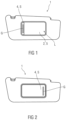
- FIG. 1 schematically, a sun shield with integrated illumination unit and open covering element designed as a sliding covering
- FIG. 2 schematically, the sun shield with integrated illumination unit and closed covering element formed as a sliding covering
- FIG. 3 schematically, the sun shield with a covering element designed as a creasing covering in a closed position
- FIG. 4 schematically, the sun shield with the partially folded back covering element designed as the creased covering
- FIG. 5 schematically, the sun shield with the covering element designed as a creasing covering in an open position
- FIG. 6 schematically, a cut-out of a vehicle with a driver as the occupant and an incident angle range
- FIG. 7 schematically, a driver as an occupant and a region of different incident angles.
- FIGS. 1 and 2 show a sun shield 1 with an integrated illumination unit 2 for a vehicle 3 depicted in sections in FIGS. 6 and 7 .
- a covering element 4 of a light outlet surface L of a light source 5 of the illumination unit 2 is designed as a sliding covering S, wherein this is shown in an open position in FIG. 1 and in a closed position in FIG. 2 .
- the illumination unit 2 comprises a light source 5 , which can be formed as an LED surface light and emits biologically effective light, wherein this is irradiated in a diffusely scattering manner across the light outlet surface L.
- the light outlet surface L is designed rectangularly to be milky white, wherein the light outlet surface L occupies a comparatively large area in relation to the surface side of the sun shield 1 .
- more than one light source 5 are provided for irradiating the biologically effective light.
- the light source 5 is integrated into a surface side of the sun shield 1 , wherein this surface side in a non-usage position is facing towards an occupant 6 shown in FIGS. 6 and 7 . If the sun shield 1 is in a usage position, the surface side with the light source 5 is facing away from the occupant 6 and facing towards a windscreen of the vehicle 3 (not shown in more detail). In the usage position of the sun shield 1 , this serves to extensively avoid dazzling an occupant 6 of the vehicle 3 by incident sunlight.
- a mirror in particular a so-called make-up mirror, is arranged on a surface side of the sun shield 1 opposite the illumination unit 2 . If the sun shield 1 has such a mirror, then it can serve as a cooling surface for the illumination unit 2 , in particular the light source 5 .
- the illumination unit 2 in particular the light outlet surface L of the light source 5 , integrated into the sun shield 1 is facing towards the occupant 6 , wherein, if the covering element 4 has a closed position, the light outlet surface L is covered by means of it.
- the light outlet surface L is arranged on the surface side of the sun shield 1 for user friendliness, which is allocated to the occupant 6 in the non-usage position, since an additional illumination device that can be activated by means of the illumination unit 2 is namely useful when the natural sun radiation is relatively low. In such a state, the sun shield 1 is usually in the non-usage position.
- the sun shield 1 i.e., the light outlet surface L of the light source 5
- the sun shield 1 is positioned in relation to the occupant 6 , to whom the sun shield 1 is allocated in terms of seating, in such a way that the biologically effective light is detected by receptors of the eyes 7 of the occupant 6 without the occupant 6 being dazzled.
- the biologically effective light emitted by means of the light source 5 reaches the eye 7 of the occupant 6 when the sun shield 1 is in the non-usage position.
- the covering element 4 is formed as a sliding covering S, wherein a view of the illumination unit 2 , in particular of the light outlet surface L, is possible after lateral shifting of the sliding covering S from right to left.
- a grip element G is arranged or formed on the covering element 4 in the form of the sliding covering S for improved handling of the sliding covering S, i.e., for improved shifting.
- the covering element 4 can be designed from an identical or adjusted material, in particular in relation to the surface structure and color, to the surroundings of the covering element 4 , i.e., a region surrounding it of the surface side of the sun shield 1 .
- the covering element 4 is formed from the same material as the sun shield 1 on this surface side and thus has the same surface structure and color, then the covering element 4 is comparatively unobtrusive in terms of its closed position. Failing that, the covering element 4 can serve as an eyecatcher and have a corresponding surface structure and/or color.
- the covering element 4 can function as a switching element for activating and deactivating the light source 5 , i.e., for switching it on and off.
- the light source 5 is thus switched on when the covering element 4 , according to the present exemplary embodiment the sliding covering S, is opened. If the covering element 4 is closed, such that the light outlet surface L of the light source is covered, this is deactivated, i.e., switched off.
- the covering element 4 can thus form a switching unit of the illumination unit 2 or alternatively is in effective connection at least with a switching unit for switching the light source 5 on and off.
- the switching unit is defective, such that the light source 5 cannot be deactivated and biologically effective light is continuously emitted, then the light source 5 can be covered by means of the covering element 4 , such that the risk of dazzling the occupant 6 , to whose seat the sun shield 1 , i.e., the light outlet surface L, is allocated, is extensively precluded.
- FIGS. 3 to 5 show the sun shield 1 having a covering element 5 formed as a flexible creasing covering A for covering the light source 5 of the illumination unit 2 .
- the creasing covering A is shown in the closed position, wherein the light source 5 is completely covered.
- FIG. 4 shows the covering element 4 in the form of the creasing covering A in the partially folded back state and in FIG. 5 , the covering element 4 of the illumination unit 2 is depicted in the open position, such that a light outlet surface L of the light source 5 is completely exposed.
- the covering element 4 designed as a creasing cover A can be folded back from left to right to expose the light outlet surface L, such that a handling of the covering element 4 is relatively simple at least for a driver as the occupant 6 .
- a recessed grip M is formed on the sun shield 1 to the left of the covering element 4 designed as a creasing covering A, such that gripping the creasing covering A is possible in an extensively unproblematic manner.
- the creasing cover A In the folded back state, i.e., in the open position, of the creasing cover A, it can be fixed on the surface side of the sun shield 1 , wherein the fixing can be implemented magnetically, for example, by means of a Velcro and/or button connection.
- the covering element 4 is formed as a flexible folding covering, such that a width of such a creasing covering A is reduced in the open position and accordingly there is a smaller space requirement.
- the covering element 4 can also be fixed in the open position, such that the covering element 4 can be prevented from pivoting caused by the driving operation.
- FIG. 6 a cut-out of a vehicle 3 , in particular a vehicle roof 8 , is shown, wherein a driver is additionally depicted as the occupant 6 of the vehicle 3 .
- FIG. 6 in addition to the sun shield 1 , various further installation positions E 2 to E 5 of the illumination unit 2 are also depicted as the installation position E 1 .
- a second installation position E 2 is in the roof region, in particular on the roof liner, wherein the illumination unit 2 is only visible when the sun shield 1 is in the usage position.
- a third installation position E 3 is in front of the sun shield 1 in the driving direction x of the vehicle 3 in the roof region, wherein a fourth installation position E 4 is arranged behind the sun shield 1 in the driving direction x.
- a fifth installation position E 5 is positioned in the roof region between the two B columns of the vehicle 3 (not depicted in more detail), for example in the region of a mirror and/or roller blind.
- sun shields 1 are also provided for occupants 6 in the back seat region, into which sun shields an illumination unit can be integrated in each case for emitting biologically effective light.
- the arrangement of such an illumination unit 2 in a back seat cosmetic mirror or in a different position suitable for an occupant 6 in the front region or back seat region of the vehicle 3 is also conceivable.
- a covering element 4 is always provided by means of which the light outlet surface L of the light source 5 can be covered.
- FIG. 7 shows a cut-out of the vehicle 3 with the occupant 6 and a region of incident angles for an eye 7 of the occupant 6 .
- an angle ⁇ between a front edge K 1 of the light outlet surface L in the non-usage position of the sun shield 1 and a straight outlook line GL of the occupant 6 can be, for example, 15°
- an angle ⁇ between a rear edge K 2 of the light outlet surface L and the straight outlook line GL can be, for example, 21°.
- the eye 7 of the occupant 6 detects the biologically effective light of the light source 5 , wherein the occupant 6 being dazzled by this light can be extensively precluded.
- an intensity of the biologically effective light emitted by means of the light source 5 can be controlled by means of an illumination strength and a color temperature of a surroundings light of the occupant 6 , wherein at least one detection unit is provided to do so for detecting the illumination strength and the color temperature of the surroundings light.
- the activation and deactivation of the illumination unit 2 is carried out depending on detected signals of the detection unit. If the illumination strength, in particular, falls below a predetermined value, it can be provided that an indication to the occupant 6 , in particular the driver of the vehicle 3 , is emitted to activate the illumination unit 2 and/or to expose the light outlet surface L by corresponding positioning of the covering element 4 .
Landscapes
- Engineering & Computer Science (AREA)
- Mechanical Engineering (AREA)
- Arrangements Of Lighting Devices For Vehicle Interiors, Mounting And Supporting Thereof, Circuits Therefore (AREA)
Applications Claiming Priority (3)
| Application Number | Priority Date | Filing Date | Title |
|---|---|---|---|
| DE102019004298.0 | 2019-06-17 | ||
| DE102019004298.0A DE102019004298B4 (de) | 2019-06-17 | 2019-06-17 | Beleuchtungseinheit und Fahrzeug |
| PCT/EP2020/062808 WO2020254037A1 (de) | 2019-06-17 | 2020-05-08 | Beleuchtungseinheit und fahrzeug |
Publications (2)
| Publication Number | Publication Date |
|---|---|
| US20220305985A1 US20220305985A1 (en) | 2022-09-29 |
| US11661002B2 true US11661002B2 (en) | 2023-05-30 |
Family
ID=70681811
Family Applications (1)
| Application Number | Title | Priority Date | Filing Date |
|---|---|---|---|
| US17/596,664 Active US11661002B2 (en) | 2019-06-17 | 2020-05-08 | Illumination unit and vehicle |
Country Status (4)
| Country | Link |
|---|---|
| US (1) | US11661002B2 (de) |
| CN (1) | CN114025992A (de) |
| DE (1) | DE102019004298B4 (de) |
| WO (1) | WO2020254037A1 (de) |
Families Citing this family (2)
| Publication number | Priority date | Publication date | Assignee | Title |
|---|---|---|---|---|
| CN111469634A (zh) * | 2020-04-01 | 2020-07-31 | 刘锋 | 多功能遮阳板及其控制方法、车辆 |
| DE102022129755A1 (de) | 2022-11-10 | 2024-05-16 | Bayerische Motoren Werke Aktiengesellschaft | Kraftfahrzeug |
Citations (10)
| Publication number | Priority date | Publication date | Assignee | Title |
|---|---|---|---|---|
| US4807093A (en) | 1987-11-16 | 1989-02-21 | Prince Corporation | Two-way vanity mirror visor |
| DE3930122A1 (de) | 1989-05-18 | 1990-11-22 | Zipperle Eugen Gmbh & Co Kg | Sonnenblende fuer kraftfahrzeuge |
| JPH0650988U (ja) | 1992-12-22 | 1994-07-12 | デルタ工業株式会社 | 自動車用覚醒照明装置 |
| DE10232797A1 (de) | 2002-07-19 | 2004-01-29 | Volkswagen Ag | Verfahren und Vorrichtung zur Steigerung der Vigilanz eines Führers eines Fahrzeuges, insbesondere eines Kraftfahrzeuges |
| JP2010120445A (ja) | 2008-11-18 | 2010-06-03 | Toyoda Gosei Co Ltd | 車両用サンバイザ |
| DE102013016817A1 (de) | 2013-10-10 | 2015-04-16 | Daimler Ag | Innraumlichtsystem für einen Innenraum eines Fahrzeugs |
| DE102016213629A1 (de) | 2016-07-26 | 2018-02-01 | Audi Ag | Beleuchtungsanordnung für einen Innenraum eines Kraftfahrzeugs |
| DE102016215593A1 (de) | 2016-08-19 | 2018-02-22 | Volkswagen Aktiengesellschaft | System zum Beleuchten eines Innenraums eines Fahrzeugs und Verfahren zum Betreiben des Systems |
| US20180131908A1 (en) * | 2016-11-10 | 2018-05-10 | Ford Global Technologies, Llc | Visor assembly for a vehicle |
| DE102017006487A1 (de) | 2017-07-08 | 2018-07-26 | Daimler Ag | Sonnenblende mit Spiegeleinheit |
Family Cites Families (3)
| Publication number | Priority date | Publication date | Assignee | Title |
|---|---|---|---|---|
| CN100465032C (zh) * | 2001-11-19 | 2009-03-04 | 乌韦·彼得·布劳恩 | 光学防眩目装置 |
| EP2842464B1 (de) * | 2012-06-01 | 2021-04-14 | Pioneer Corporation | Leuchtspiegelvorrichtung und beleuchtungssteuerungsverfahren dafür |
| DE102016203164A1 (de) * | 2015-05-26 | 2016-12-01 | Ford Global Technologies, Llc | Lichttherapie-Beleuchtungssystem für einen Fahrzeuginnenraum |
-
2019
- 2019-06-17 DE DE102019004298.0A patent/DE102019004298B4/de active Active
-
2020
- 2020-05-08 US US17/596,664 patent/US11661002B2/en active Active
- 2020-05-08 WO PCT/EP2020/062808 patent/WO2020254037A1/de active Application Filing
- 2020-05-08 CN CN202080044369.6A patent/CN114025992A/zh active Pending
Patent Citations (10)
| Publication number | Priority date | Publication date | Assignee | Title |
|---|---|---|---|---|
| US4807093A (en) | 1987-11-16 | 1989-02-21 | Prince Corporation | Two-way vanity mirror visor |
| DE3930122A1 (de) | 1989-05-18 | 1990-11-22 | Zipperle Eugen Gmbh & Co Kg | Sonnenblende fuer kraftfahrzeuge |
| JPH0650988U (ja) | 1992-12-22 | 1994-07-12 | デルタ工業株式会社 | 自動車用覚醒照明装置 |
| DE10232797A1 (de) | 2002-07-19 | 2004-01-29 | Volkswagen Ag | Verfahren und Vorrichtung zur Steigerung der Vigilanz eines Führers eines Fahrzeuges, insbesondere eines Kraftfahrzeuges |
| JP2010120445A (ja) | 2008-11-18 | 2010-06-03 | Toyoda Gosei Co Ltd | 車両用サンバイザ |
| DE102013016817A1 (de) | 2013-10-10 | 2015-04-16 | Daimler Ag | Innraumlichtsystem für einen Innenraum eines Fahrzeugs |
| DE102016213629A1 (de) | 2016-07-26 | 2018-02-01 | Audi Ag | Beleuchtungsanordnung für einen Innenraum eines Kraftfahrzeugs |
| DE102016215593A1 (de) | 2016-08-19 | 2018-02-22 | Volkswagen Aktiengesellschaft | System zum Beleuchten eines Innenraums eines Fahrzeugs und Verfahren zum Betreiben des Systems |
| US20180131908A1 (en) * | 2016-11-10 | 2018-05-10 | Ford Global Technologies, Llc | Visor assembly for a vehicle |
| DE102017006487A1 (de) | 2017-07-08 | 2018-07-26 | Daimler Ag | Sonnenblende mit Spiegeleinheit |
Non-Patent Citations (3)
| Title |
|---|
| International Search Report dated Jul. 16, 2020 in related/corresponding International Application No. PCT/EP2020/062808. |
| Office Action created Feb. 19, 2020 in related/corresponding DE Application No. 10 2019 004 298.0. |
| Written Opinion dated Jul. 16, 2020 in related/corresponding International Application No. PCT/EP2020/062808. |
Also Published As
| Publication number | Publication date |
|---|---|
| DE102019004298A1 (de) | 2020-12-17 |
| DE102019004298B4 (de) | 2021-03-25 |
| WO2020254037A1 (de) | 2020-12-24 |
| US20220305985A1 (en) | 2022-09-29 |
| CN114025992A (zh) | 2022-02-08 |
Similar Documents
| Publication | Publication Date | Title |
|---|---|---|
| US7301466B2 (en) | Turn signal lamp, periphery monitoring device, body construction and imaging device for vehicle | |
| US7204625B2 (en) | Phototherapy device | |
| US10399414B2 (en) | Method for operating a dazzle protection system for a vehicle | |
| US20090058126A1 (en) | Glare reduction | |
| US11661002B2 (en) | Illumination unit and vehicle | |
| US10286840B2 (en) | Vehicle lighting assembly using panel with light reflecting film | |
| EP3274620B1 (de) | Leuchte | |
| US6616312B2 (en) | Convenience lighting for interior and exterior vehicle applications | |
| US20110019391A1 (en) | Sun visor with lighting device | |
| US6598982B2 (en) | Rearview mirror alignment device | |
| US20120327674A1 (en) | Vehicle visor having hidden light assembly | |
| JP6793716B2 (ja) | 自動車の車室のためのバニティミラーユニット | |
| CN108916807B (zh) | 具有光致变色透镜和透镜加热系统的车辆前照灯系统 | |
| JP2007069808A (ja) | 車両用サンバイザ | |
| KR101885477B1 (ko) | 후방주차시 시야확보를 위한 조명등 | |
| JP5252727B2 (ja) | 車室内照明装置 | |
| JP4214882B2 (ja) | 車両周辺暗視用灯具および車両用アウトサイドミラー装置 | |
| US10871265B2 (en) | Vehicular headlamp system with a photochromic lens | |
| GB2520126A (en) | A Sun Visor Assembly For A motor Vehicle And A Vehicle With A Sun Visor Assembly | |
| JP2019137186A (ja) | 車両 | |
| KR20180130757A (ko) | 차량용 선바이저의 조명장치 | |
| JP5252726B2 (ja) | 車室内照明装置 | |
| KR101664566B1 (ko) | 스팟 램프를 이용한 선글라스 케이스 무드 조명 | |
| JP2024057984A (ja) | 車載照明装置 | |
| KR20010030351A (ko) | 차량의 방향성 조명 장치 |
Legal Events
| Date | Code | Title | Description |
|---|---|---|---|
| FEPP | Fee payment procedure |
Free format text: ENTITY STATUS SET TO UNDISCOUNTED (ORIGINAL EVENT CODE: BIG.); ENTITY STATUS OF PATENT OWNER: LARGE ENTITY |
|
| AS | Assignment |
Owner name: MERCEDES-BENZ GROUP AG, GERMANY Free format text: ASSIGNMENT OF ASSIGNORS INTEREST;ASSIGNOR:BAUER, STEFAN;REEL/FRAME:059283/0383 Effective date: 20220221 Owner name: DAIMLER AG, GERMANY Free format text: ASSIGNMENT OF ASSIGNORS INTEREST;ASSIGNORS:BETZ, DANIEL;FUHRMANN, DANIEL;SCHUELER, SEBASTIAN;SIGNING DATES FROM 20211202 TO 20211214;REEL/FRAME:059283/0363 |
|
| STPP | Information on status: patent application and granting procedure in general |
Free format text: DOCKETED NEW CASE - READY FOR EXAMINATION |
|
| STCF | Information on status: patent grant |
Free format text: PATENTED CASE |