US11519093B2 - Apparatuses, systems, and methods for producing a plurality of articles with nanolaminated coatings using rotation - Google Patents
Apparatuses, systems, and methods for producing a plurality of articles with nanolaminated coatings using rotation Download PDFInfo
- Publication number
- US11519093B2 US11519093B2 US17/050,395 US201917050395A US11519093B2 US 11519093 B2 US11519093 B2 US 11519093B2 US 201917050395 A US201917050395 A US 201917050395A US 11519093 B2 US11519093 B2 US 11519093B2
- Authority
- US
- United States
- Prior art keywords
- workpieces
- workpiece
- rpm
- layers
- conductive
- Prior art date
- Legal status (The legal status is an assumption and is not a legal conclusion. Google has not performed a legal analysis and makes no representation as to the accuracy of the status listed.)
- Active
Links
Images


Classifications
-
- C—CHEMISTRY; METALLURGY
- C25—ELECTROLYTIC OR ELECTROPHORETIC PROCESSES; APPARATUS THEREFOR
- C25D—PROCESSES FOR THE ELECTROLYTIC OR ELECTROPHORETIC PRODUCTION OF COATINGS; ELECTROFORMING; APPARATUS THEREFOR
- C25D17/00—Constructional parts, or assemblies thereof, of cells for electrolytic coating
- C25D17/06—Suspending or supporting devices for articles to be coated
- C25D17/08—Supporting racks, i.e. not for suspending
-
- C—CHEMISTRY; METALLURGY
- C25—ELECTROLYTIC OR ELECTROPHORETIC PROCESSES; APPARATUS THEREFOR
- C25D—PROCESSES FOR THE ELECTROLYTIC OR ELECTROPHORETIC PRODUCTION OF COATINGS; ELECTROFORMING; APPARATUS THEREFOR
- C25D17/00—Constructional parts, or assemblies thereof, of cells for electrolytic coating
- C25D17/10—Electrodes, e.g. composition, counter electrode
- C25D17/12—Shape or form
-
- C—CHEMISTRY; METALLURGY
- C25—ELECTROLYTIC OR ELECTROPHORETIC PROCESSES; APPARATUS THEREFOR
- C25D—PROCESSES FOR THE ELECTROLYTIC OR ELECTROPHORETIC PRODUCTION OF COATINGS; ELECTROFORMING; APPARATUS THEREFOR
- C25D5/00—Electroplating characterised by the process; Pretreatment or after-treatment of workpieces
- C25D5/54—Electroplating of non-metallic surfaces
- C25D5/56—Electroplating of non-metallic surfaces of plastics
-
- C—CHEMISTRY; METALLURGY
- C25—ELECTROLYTIC OR ELECTROPHORETIC PROCESSES; APPARATUS THEREFOR
- C25D—PROCESSES FOR THE ELECTROLYTIC OR ELECTROPHORETIC PRODUCTION OF COATINGS; ELECTROFORMING; APPARATUS THEREFOR
- C25D7/00—Electroplating characterised by the article coated
- C25D7/04—Tubes; Rings; Hollow bodies
Definitions
- the present disclosure generally relates to apparatuses, systems, and methods for electrodepositing coatings onto cylindrical articles, and more specifically to electrodepositing compositionally modulated (e.g., concentration of metals in an alloy, etc.) or structurally modulated (e.g., layer thickness, layer density, etc.), nano- or microlaminate coatings.
- compositionally modulated e.g., concentration of metals in an alloy, etc.
- structurally modulated e.g., layer thickness, layer density, etc.
- Electrodeposition techniques typically require large contact areas between the electrical power source and the workpiece, and a known distance between the workpiece and an anode. This is particularly problematic for workpieces with complex geometries, such as cylindrical workpieces. Due to the shape of the workpiece, it is difficult to produce a coating that is substantially uniform in thickness, and, in particular, when attempting to coat multiple workpieces at once.
- the present disclosure provides an apparatus comprising: at least one support structure configured to support a plurality of workpieces around a rotational axis, each workpiece of the plurality of workpieces having a substantially cylindrical shape with an outer surface and a longitudinal axis; and a drive assembly configured to rotate the plurality of workpieces around the rotational axis.
- an apparatus further comprises a contact point assembly is further configured to enable electrical contact with the plurality of workpieces.
- the contact point assembly is configured to rotate each workpiece of the plurality of workpieces rotate around its respective longitudinal axis.
- the present disclosure provides a system comprising: a plurality of workpieces around a rotational axis, each workpiece of the plurality of workpieces having a substantially cylindrical shape with an outer surface and a longitudinal axis; and an apparatus described herein.
- individual workpieces of the plurality of workpieces are coupled in series with individual couplers of the plurality of couplers arranged between the individual workpieces.
- the present disclosure provides a method for producing a nanolaminate coating on a plurality of workpieces, the method comprising: introducing the plurality of workpieces, each workpiece being substantially cylindrical, having a longitudinal axis, and having an outer surface, to a system described herein; rotating the plurality of workpieces around a rotational axis at a rotational speed; and electrodepositing an electrodepositable species onto the plurality of workpieces as a first nanolaminate coating on at least a portion of the outer surface of each of the plurality of workpieces
- FIGS. 1 A- 1 C are several views of an example of an electrodeposition apparatus of the disclosure.
- FIG. 2 is a view of a gear system of an embodiment of an electrodeposition apparatus of the disclosure.
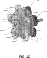
- FIGS. 3 A- 3 C are several views of an embodiment of a contact point assembly of an apparatus of the disclosure.
- FIGS. 4 A- 4 C are illustrative embodiments of anodes of the present disclosure.
- FIG. 5 is a view of an illustrative embodiment of a needle roller bearing.
- FIGS. 6 A- 6 C are several views of an illustrative example of a system of the disclosure.
- FIGS. 7 A- 7 D are several views of an embodiment of an electrodeposition apparatus of the disclosure.
- FIG. 8 is a view of an illustrative embodiment of a rack and conductive bus of the disclosure.
- FIGS. 9 A and 9 B are views of an embodiment of an electrodeposition apparatus of the disclosure.
- FIG. 10 is a view of an embodiment of an electrodeposition apparatus of the disclosure.
- FIGS. 11 A- 11 G are several views of an embodiment of a system and apparatus of the disclosure.
- the present disclosure is generally directed to electrodeposited nanolaminate coatings on tubular substrates, which have improved heat, wear, and corrosion resistance, as well as methods of making and using the same.
- Electrodeposition or “electrodeposited” refers to a process or a resultant product, respectively, in which electrolysis is used to deposit a coating onto a workpiece.
- a workpiece is contacted with (e.g., partially immersed in, or fully immersed in) an electrolyte solution containing one or more ions (e.g., metal, ceramic, etc.) while an electric current is passed through the workpiece and the electrolyte solution, resulting in a thin coating being deposited on the surface of the workpiece.
- an electrodeposited coating that includes two or more layers may be referred to as a “laminate” coating.
- coatings include any thin layers that are electrodeposited onto a surface of a workpiece. Therefore “coatings,” as used herein, includes claddings, which are made of a series of thin electrodeposited layers on a surface of a mandrel, where the mandrel is removed after formation of the electrodeposited layers. Claddings are generally fastened to another article as a protective layer after formation.
- a “nanolaminate coating” refers to an electrodeposited coating that includes at least one layer with a thickness of less than 10,000 nanometers (i.e., 10 microns).
- a nanolaminate coating includes two or more layers in which individual layers have a thickness of less than 10,000 nanometers.
- processes described herein are particularly suited for providing nanolaminate coatings, the same or similar processes can also be used to make similar articles in which individual layers that are thicker than 10 microns. Such coatings may be referred to as “microlaminate coatings.”
- workpiece includes any item with a surface onto which a coating is electrodeposited.
- Workpieces include substrates, which are objects on which a coating is applied, and mandrels, which are substrates from which the coating is removed after formation.
- substrates which are objects on which a coating is applied
- mandrels which are substrates from which the coating is removed after formation.
- cylindrical workpieces are used.
- Cylindrical workpieces have a substantially cylindrical shape and a longitudinal axis, which runs from a center of one base of the substantially cylindrical shape to a center of the other base.
- “cylindrical workpieces” include tubular workpieces and columnar workpieces.
- Trobular workpieces have a substantially cylindrical shape and a hollow cavity defined by an inner surface of a tubular workpiece.
- a hollow cavity of a tubular workpiece is generally substantially cylindrical in shape and is aligned along a longitudinal axis. Additionally, a base of a hollow cavity is centered substantially in the center of a base of a tubular workpiece.
- a “columnar workpiece” is substantially cylindrical, but does not have a hollow cavity.
- An “article” describes a finished product of a workpiece that has been coated by a method as described herein. Therefore, an article is a workpiece with a nanolaminate or microlaminate coating.
- “Balance” or “balance of the composition,” as used herein in reference to the composition of materials, refers to the portion of the composition not defined by an explicit amount or range, or, in other words, the remainder of the composition.
- substantially has the meaning reasonably ascribed to it by a person of ordinary skill in the art when used to describe a physical characteristic of an item, i.e., indicating that the item possesses the referenced characteristic to a significant extent, e.g., to within a range of ⁇ 20% of the referenced characteristic; ⁇ 19% of the referenced characteristic; ⁇ 18% of the referenced characteristic; ⁇ 17% of the referenced characteristic; ⁇ 16% of the referenced characteristic; ⁇ 15% of the referenced characteristic; ⁇ 14% of the referenced characteristic; ⁇ 13% of the referenced characteristic; ⁇ 12% of the referenced characteristic; ⁇ 11% of the referenced characteristic; ⁇ 10% of the referenced characteristic; ⁇ 9% of the referenced characteristic; ⁇ 8% of the referenced characteristic; ⁇ 7% of the referenced characteristic; ⁇ 6% of the referenced characteristic; ⁇ 5% of the referenced characteristic; ⁇ 4% of the referenced characteristic; ⁇ 3% of the referenced characteristic; ⁇ 2% of the referenced characteristic; or
- an item may be considered substantially circular if any two measurements of a diameter of the item are within a range of ⁇ 20%, ⁇ 19%; ⁇ 18%; ⁇ 17%; ⁇ 16%; ⁇ 15%; ⁇ 14%; ⁇ 13%; ⁇ 12%; ⁇ 11%; ⁇ 10%; ⁇ 9%; ⁇ 8%; ⁇ 7%; ⁇ 6%; ⁇ 5%; ⁇ 4%; ⁇ 3%; ⁇ 2%; or ⁇ 1% of each other.
- a first coating is substantially thicker than a second coating
- substantially is used to mean that the difference is at least ⁇ 20% of the referenced characteristic; ⁇ 19% of the referenced characteristic; ⁇ 18% of the referenced characteristic; ⁇ 17% of the referenced characteristic; ⁇ 16% of the referenced characteristic; ⁇ 15% of the referenced characteristic; ⁇ 14% of the referenced characteristic; ⁇ 13% of the referenced characteristic; ⁇ 12% of the referenced characteristic; ⁇ 11% of the referenced characteristic; ⁇ 10% of the referenced characteristic; ⁇ 9% of the referenced characteristic; ⁇ 8% of the referenced characteristic; ⁇ 7% of the referenced characteristic; ⁇ 6% of the referenced characteristic; ⁇ 5% of the referenced characteristic; ⁇ 4% of the referenced characteristic; ⁇ 3% of the referenced characteristic; ⁇ 2% of the referenced characteristic; or ⁇ 1% of the referenced characteristic.
- any number range recited herein relating to any physical feature, such as size or thickness, are to be understood to include any integer within the recited range, unless otherwise indicated. Unless otherwise indicated herein, each individual value is incorporated into the specification as if it were individually recited herein.
- each embodiment disclosed herein can comprise, consist essentially of, or consist of a particular stated element, step, ingredient, or component.
- the term “comprise” or “comprises” means “includes, but is not limited to,” and allows for the inclusion of unspecified elements, steps, ingredients, or components, even in major amounts.
- the phrase “consisting of” excludes any element, step, ingredient, or component that is not specified.
- the phrase “consisting essentially of” limits the scope of the embodiment to the specified elements, steps, ingredients, or components, and to those that do not materially affect the basic and novel characteristics of the claimed disclosure.
- Apparatuses for Electrodepositing Nanolaminate Coatings Articles of the present disclosure may be produced using specialized apparatuses.
- Apparatuses of the present disclosure include a support structure, which is designed to support a plurality of workpieces arranged around a rotational axis.
- the support structure of the present disclosure comprises one or more guides 102 a , 102 b , which are used to arrange the plurality of workpieces 106 around the rotational axis, as shown in FIG. 1 A .
- Guides may be made of any suitable materials.
- the material is non-conductive and inert when contacted with an electrolyte solution.
- guides may be formed from an acrylic, delrin, or the like.
- a plurality of workpieces is arranged substantially parallel to each other.
- the plurality of workpieces is arranged in a polygonal configuration, as shown in FIG. 2 .
- lines connecting the longitudinal axis 218 a , 218 b , 218 c , 218 d , 218 e of each of the plurality of workpieces, when viewed in a direction parallel to the longitudinal axes, would form a polygon, as illustrated in FIG. 2 by the dashed lines.
- the polygon formed has three sides.
- the polygon formed has four sides.
- the polygon formed has five sides, as shown in FIG. 2 .
- the polygon formed has six sides, as shown in FIG. 7 A .
- the plurality of workpieces is spaced such that the individual workpieces do not make physical contact.
- the plurality of workpieces are spaced such that the distance between the individual workpieces is at least about the same as the outer diameter of a workpiece.
- the support structure supports a plurality of workpieces that are arranged in a planar configuration. In other words, two the workpieces are arranged next to each other in a line, such that first ends of the workpieces are aligned, second ends of the workpieces are aligned, and midpoints of the workpieces are aligned.
- the rotational axis may be a longitudinal axis of one of the workpieces.
- the at least one support structure of the present disclosure comprises a support member 104 that supports the plurality of workpieces 106 during the electrodeposition process.
- the support member(s) 104 couple to a rack 108 .
- the support member(s) 104 are integrated with a rack 108 .
- support members 804 and/or rack 808 may have attachments 862 that allow a support member 804 and/or rack 808 to be coupled to (e.g., suspended from) an overhead gantry or gantry system that allows the plurality of workpieces to be transported between processing tanks, holding areas, storage areas, and the like, as shown in FIG. 8 .
- support members 804 and/or rack 808 may have attachments that allow a support member to be coupled to (e.g., supported by) a vehicle such as, a trolley or a tractor, in order to facilitate transport.
- a gantry system or a vehicle is automated.
- a gantry crane or vehicle is coupled to a rack during an electrodeposition process.
- a gantry crane or a vehicle releases the support member(s) during an electrodeposition process.
- a same gantry crane or vehicle re-couples with the support member(s) after completion.
- a different gantry crane or vehicle may couple with the support member(s) after completion.
- support member 104 is not physically connected to a second support member (not pictured), and, therefore, is configurable to support workpieces 106 of various lengths.
- support member 104 supports a workpieces 106 with a length ranging from about 0.1 meters (m) to 15 m.
- support member 104 supports a workpieces 106 that has a length ranging from about 0.10 m to about 0.15 m; from about 0.10 m to about 0.5 m; from about 0.10 m to about 1.0 m; from about 0.10 m to about 0.4 m; from about 0.10 m to about 1.51 m; from about 0.10 m to about 10.7 m; from about 0.10 m to about 13.8 m; from about 0.15 m to about 0.4 m; from about 0.15 m to about 1.51 m; from about 0.15 m to about 10.7 m; from about 0.15 m to about 13.8 m; from about 0.3 m to about 0.7 m; from about 0.6 m to about 1.51 m; from about 1 m to about 2 m; from about 1 m to about 5 m; from about 1 m to about 14.5 m; from about 1.5 m to about 3.1 m; from about 1.5 m to about 6.1 m; from about 2
- the support structures are designed to support a plurality of workpieces where each of the workpieces has substantially the same length, substantially the same outer diameter, substantially the same inner diameter, or a combination thereof.
- support member 104 is configured to accommodate workpieces 106 with a fixed length ranging from about 0.1 m to 15 m.
- support member 104 support a workpieces 106 with a length of about 0.15 m, about 0.3 m, about 0.4 m, about 0.6 m, about 0.7 m, about 1 m, about 1.5 m, about 2 m, about 3 m, about 4 m, about 5 m, about 6 m, about 7 m, about 8 m, about 9 m, about 10 m, about 11 m, about 12 m, about 13 m, about 14 m, or about 15 m.
- additional support members are added to the rack in order to provide additional support for the workpieces.
- additional support members are generally added at or near a mid-point of the workpiece arrangements.
- Support structures of the present disclosure may hold workpieces 106 such that a longitudinal axis of the workpieces is substantially horizontal. In other embodiments, support structures hold workpieces such that the longitudinal axis is at an incline ranging from about 0.5 degrees to about 2.5 degrees relative to horizontal. In some embodiments, support structures hold a workpieces 106 such that a longitudinal axis is at an incline ranging from about 0.5 degrees to about 1 degree; from about 1 degree to about 1.5 degrees; from about 1.5 degrees to about 2 degrees; or from about 2 degrees to about 2.5 degrees.
- Support structures of the present disclosure may hold workpieces 106 such that the rotational axis of the plurality of workpieces is substantially horizontal. In other embodiments, support structures hold the workpieces such that a rotational axis is at an incline ranging from about 0.5 degrees to about 2.5 degrees relative to horizontal. In some embodiments, support structures hold workpieces 106 such that the rotational axis is at an incline ranging from about 0.5 degrees to about 1 degree; from about 1 degree to about 1.5 degrees; from about 1.5 degrees to about 2 degrees; or from about 2 degrees to about 2.5 degrees.
- support structures may further comprise one or more support rods 110 .
- Such support rods 110 may be coupled to other support structures, such as guides 102 a , 102 b .
- such support rods are positioned in order to prevent flexing in the apparatus.
- at least two support rods are present.
- at least three support rods are present.
- at least four support rods are present.
- at least five support rods are present.
- Such support rods are generally centered around the rotational axis.
- Support structures may be fabricated from a non-conductive material such as, polyvinylchloride (PVC), polyethylene (e.g. high density polyethylene (HDPE), acrylonitrile butadiene styrene (ABS), polypropylene (PP), or any combination thereof.
- a support structure is made of a conductive material.
- a support structure is made of a conductive material or a non-conductive material may be coated with a non-conductive coating such as, PVC, polyethylene, polycarbonate, polyurethane, synthetic rubber, acrylic, or any combination thereof.
- An apparatus of the present disclosure further comprises a drive assembly that rotates the plurality of workpieces 106 around the rotational axis 114 .
- an apparatus of the present disclosure comprises at least one support structure configured to support a plurality of workpieces around a rotational axis, each workpiece of the plurality of workpieces having a substantially cylindrical shape with an outer surface and a longitudinal axis; and a drive assembly configured to rotate the plurality of workpieces around the rotational axis.
- a drive assembly comprises a central rod 112 that is aligned along the rotational axis 114 .
- a central rod 112 is made of a suitable non-conductive material (e.g., a plastic or a polymeric material, such as a composite material).
- a central rod 112 is made of a conductive (or a non-conductive) material that is coated with a suitable non-conductive coating (e.g., a plastic or a polymeric material, such as a composite material) using methods known in the art, such as via shrink wrapping, dip coating, painting, and the like.
- Suitable non-conductive materials or coatings are chosen based on the chemistry of the electrolyte bath, such that the material or coating does not contaminate an electrolyte solution.
- a central rod 112 is made of a suitable conductive material.
- a drive assembly further comprises one or more central gears 120 a , 120 b , which surround central rod 112 .
- central gear 120 a surrounds central rod 112 , around which the plurality of workpieces 106 are arranged.
- central gears 120 a may be arranged near (e.g., next to) a guide 102 a.
- central gear 220 surrounds central rod 212 .
- a central gear 220 is engaged by a motor to rotate a plurality of workpieces around a rotational axis.
- a motor may be submerged in an electrolyte solution in a processing tank.
- a motor may be housed in a suitable housing.
- a housing is fabricated from a polymeric material (e.g., composite, thermoplastic, or thermoset) that is sealed (i.e., water tight).
- a motor 964 may, in use, be maintained outside of the electrolyte solution, as shown in FIG. 9 A .
- a pulley system 966 may be arranged to translate the motion (e.g., linear motion) from the motor to the drive assembly.
- a motor controller may be used to control a motor.
- a motor controller is used to start or stop the motor, or to vary a speed as desired.
- a motor or motor controller is a part of an apparatus of the disclosure. In other embodiments, a motor or motor controller is separate from an apparatus of the disclosure.
- a plurality of workpieces may be rotated (e.g. by a motor) around the rotational axis at a rotational speed ranging from about 0.5 revolutions per minute (rpm) to about 10 rpm.
- a plurality of workpieces is rotated (e.g., by a motor) around the rotational axis at a rotational speed ranging from about 0.5 rpm to about 3 rpm, about 1 rpm to about 4 rpm, about 2 rpm to about 5 rpm, about 3 rpm to about 6 rpm, about 4 rpm to about 7 rpm, about 5 rpm to about 8 rpm, about 6 rpm to about 9 rpm, or about 7 rpm to about 10 rpm.
- a plurality of workpieces is rotated (e.g., by a motor) around the rotational axis at a rotational speed ranging from about 0.5 rpm to about 1 rpm, about 1 rpm to about 2 rpm, about 2 rpm to about 3 rpm, about 3 rpm to about 4 rpm, about 4 rpm to about 5 rpm, about 5 rpm to about 6 rpm, about 6 rpm to about 7 rpm, about 7 rpm to about 8 rpm, about 8 rpm to about 9 rpm, or about 9 rpm to about 10 rpm.
- An apparatus described herein may further include a gear box.
- a gear box may be in a same housing as a motor, or in a second housing.
- a motor of the present disclosure may connect to a first end of a gear box.
- a gear box is a right-angle (or 90 degree) gear drive that translates linear motion from a linear motor into rotary motion.
- a second end of a gear box may be connected to a gear 220 .
- an apparatus of the present disclosure may further include one or more bearings that rotate as the plurality of workpieces rotate around the rotational axis.
- Such bearings may support the plurality of workpieces at any suitable position, such as at a coupler, at the central rod, or the like.
- the racks further include a contact point assembly that, enables electrical contact with a workpiece.
- a contact point assembly that, enables electrical contact with a workpiece.
- FIGS. 3 A- 3 C Several views of an embodiment of a contact point assembly are shown in FIGS. 3 A- 3 C .
- the contact point assembly rotates each workpiece around the respective longitudinal axis of the tubular workpiece or around an axis substantially parallel to the respective longitudinal axis.
- the contact point assembly comprises two or more peripheral rods 316 a , 316 b , 316 c that are positioned around the rotational axis 314 .
- the two or more peripheral rods 316 a , 316 b , 316 c are positioned substantially along the longitudinal axis 318 a , 318 b , 318 c , or an axis substantially parallel to the longitudinal axis within the hollow cavity of one or more workpieces.
- an inner surface of the workpieces may be coated at a separate time from (i.e., before or after) the outer surface.
- the peripheral rods have substantially the same diameter as the inner diameter of the workpiece(s) arranged on the respective peripheral rod.
- At least a portion of the plurality of workpieces 106 are arranged in series, as shown in FIG. 1 C .
- two or more workpieces are arranged on a peripheral rod.
- a first end of a first workpiece is coupled to a first end of a second workpiece
- a second end of the second workpiece is coupled to a first end of a third workpiece, and the like.
- at least three workpieces are serially coupled.
- at least four workpieces are serially coupled.
- at least five workpieces are serially coupled.
- at least 10 workpieces are serially coupled.
- at least 15 workpieces are serially coupled.
- all of the plurality of workpieces are serially coupled.
- Couplers generally are cylindrical (e.g., tubular) structures.
- each coupler includes a first threaded portion and a second threaded portion that correspond to threaded portions of workpieces, such that a threaded portion of coupler may be joined to a threaded portion of a workpiece.
- a coupler is joined to a workpiece in a manner other than corresponding threading. For example, a coupler may be welded, bonded, or fastened to the workpiece.
- a coupler is joined to a workpiece by applying pressure such that the workpiece causes the coupler to deform, either plastically or elastically.
- the coupler is deformed to show, at least temporarily, an impression of the side profile of the workpiece.
- a seal is formed between a coupler and a workpiece.
- the seal formed may be water tight, such that electrolyte solution is not able to reach the interior cavity of a tubular workpiece.
- couplers i.e., two or more types
- a first type of coupler 138 a - 138 k may be used between individual workpieces that are joined in serial
- a second type of coupler 140 a , 140 b may be used at ends of the series of workpieces.
- couplers may be made of conductive or non-conductive material, with or without a conductive or non-conductive coating.
- a coupler experiences wear during an electrodeposition process, and therefore is sacrificial.
- workpieces coupled in a series each have a length ranging from about 0.1 m to about 1 m. In particular embodiments, workpieces coupled in a series each have a length ranging from about 0.1 m to about 0.5 m.
- the contact point assembly comprises one or more peripheral gears. As shown in FIG. 2 , peripheral gears 222 a - 222 e surround peripheral rods 216 a - 216 e , respectively.
- a peripheral gear may include a threaded portion.
- a threaded portion may be internally threaded or externally threaded.
- a threaded portion of the peripheral gear corresponds to a threaded portion of a workpiece, such that a threaded portion of a peripheral gear and a threaded portion of a workpiece may be joined together.
- a peripheral gear is not joined to a workpiece or coupler.
- a threaded portion of the peripheral gear corresponds to a threaded portion of a coupler.
- a peripheral gear is joined to a workpiece or coupler in a manner other than corresponding threading.
- a peripheral gear may be welded, bonded, or fastened to a workpiece or coupler.
- a second peripheral gear is coupled to the opposite end of a workpiece or to the opposite end of a series of workpieces.
- a first and second peripheral gear may be coupled to a workpiece, or to a series of workpieces using a same manner (e.g., corresponding threading, welding, bonding, fastening, etc.) or a different manner.
- a peripheral gear 222 a - 222 e or central gear 220 is engaged by a motor (not shown) to rotate a workpiece.
- a peripheral gear of the present disclosure may be directly engaged by a motor to rotate a workpiece.
- a central gear is directly engaged by a motor, the central gear then engaging with the peripheral gears, in order to rotate the plurality of workpieces.
- a contact point assembly comprises a plurality of peripheral gears.
- a peripheral gear is coupled to a peripheral rod.
- the plurality of peripheral gears are coupled to the plurality of workpieces, respectively.
- the plurality of peripheral gears may be engaged by a single motor to rotate the workpieces.
- the plurality of peripheral gears may be engaged by two or more motors to rotate the workpieces.
- the plurality of workpieces are rotated at a same speed.
- individual workpieces of the plurality of workpieces are rotated at two or more speeds.
- portions of the plurality of workpieces are rotated independently at different speeds.
- a workpiece may be rotated (e.g. by a motor) around the longitudinal axis at an individual rotational speed ranging from about 0.5 revolutions per minute (rpm) to about 10 rpm.
- a workpiece is rotated (e.g., by a motor) around the longitudinal axis at an individual rotational speed ranging from about 0.5 rpm to about 3 rpm, about 1 rpm to about 4 rpm, about 2 rpm to about 5 rpm, about 3 rpm to about 6 rpm, about 4 rpm to about 7 rpm, about 5 rpm to about 8 rpm, about 6 rpm to about 9 rpm, or about 7 rpm to about 10 rpm.
- a workpiece is rotated around the longitudinal axis at an individual rotational speed ranging from about 0.5 rpm to about 1 rpm, about 1 rpm to about 2 rpm, about 2 rpm to about 3 rpm, about 3 rpm to about 4 rpm, about 4 rpm to about 5 rpm, about 5 rpm to about 6 rpm, about 6 rpm to about 7 rpm, about 7 rpm to about 8 rpm, about 8 rpm to about 9 rpm, or about 9 rpm to about 10 rpm.
- a motor may be submerged in an electrolyte solution in a processing tank.
- a motor may be housed in a suitable housing.
- a housing is fabricated from a polymeric material (e.g., composite, thermoplastic, or thermoset) that is sealed (i.e., water tight).
- An apparatus described herein may further comprise a pulley system to translate the motion from the motor to rotate the plurality of workpieces.
- the pulley system allows the motor to be positioned outside of an electrolyte bath, as shown in FIG. 9 A .
- at least a portion of a pulley system is housed in a suitable housing 968 . In some embodiments, such a housing is sealed.
- a motor controller may be used to control a motor.
- a motor controller is used to start or stop the motor, or to vary a speed as desired.
- a motor or motor controller is a part of an apparatus of the disclosure. In other embodiments, a motor or motor controller is separate from an apparatus of the disclosure.
- An apparatus described herein may further include a gear box.
- a gear box may be in a same housing as a motor, or in a second housing.
- a motor of the present disclosure may connect to a first end of a gear box.
- a gear box is a right-angle (or 90 degree) gear drive that translates linear motion from a linear motor into rotary motion.
- a second end of a gear box may be connected to a gear 220 .
- the support structure of the present disclosure comprises one or more guides 702 a , 702 b , which are used to arrange the plurality of workpieces 706 around the rotational axis.
- Guides may be made of any suitable materials.
- the material is non-conductive and inert when contacted with an electrolyte solution.
- guides may be formed from an acrylic, delrin, or the like.
- a plurality of workpieces is arranged substantially parallel to each other. In some embodiments, the plurality of workpieces is arranged in a polygonal configuration. In some embodiments, the polygon formed has three sides. In some embodiments, the polygon formed has four sides. In some embodiments, the polygon formed has five sides. In some embodiments, the polygon formed has six sides. In embodiments, the plurality of workpieces is spaced such that the individual workpieces do not make physical contact. In embodiments, the plurality of workpieces are spaced such that the distance between the individual workpieces is at least about the same as the outer diameter of a workpiece.
- the support structure 1004 supports a plurality of workpieces 1006 that are arranged in a planar configuration, as shown in FIG. 10 .
- two of the workpieces are arranged next to each other in a line, such that first ends of the workpieces are aligned, second ends of the workpieces are aligned, and midpoints of the workpieces are aligned.
- the rotational axis may be a longitudinal axis of one of the workpieces.
- the at least one support structure of the present disclosure comprises a support member 1004 that supports the plurality of workpieces 1006 during the electrodeposition process.
- the support member(s) 1004 couple to a rack 1008 .
- the support member(s) 1004 are integrated with a rack.
- support members 804 and/or rack 808 may have attachments 862 that allow a support member 804 and/or rack 808 to be coupled to (e.g., suspended from) an overhead gantry or gantry system that allows the plurality of workpieces to be transported between processing tanks, holding areas, storage areas, and the like, as shown in FIG. 8 .
- support members 804 and/or rack 808 may have attachments that allow a support member to be coupled to (e.g., supported by) a vehicle such as, a trolley or a tractor, in order to facilitate transport.
- a gantry system or a vehicle is automated.
- a gantry crane or vehicle is coupled to a rack during an electrodeposition process.
- a gantry crane or a vehicle releases the support member(s) during an electrodeposition process.
- a same gantry crane or vehicle re-couples with the support member(s) after completion.
- a different gantry crane or vehicle may couple with the support member(s) after completion.
- an apparatus includes two or more support members that are not physically connected together.
- support member 704 is configurable to support workpieces 706 of various lengths.
- support member 704 supports a workpieces 706 with a length ranging from about 0.1 meters (m) to 15 m.
- support member 104 supports a workpieces 106 that has a length ranging from about 0.10 m to about 0.15 m; from about 0.10 m to about 0.5 m; from about 0.10 m to about 1.0 m; from about 0.10 m to about 0.4 m; from about 0.10 m to about 1.51 m; from about 0.10 m to about 10.7 m; from about 0.10 m to about 13.8 m; from about 0.15 m to about 0.4 m; from about 0.15 m to about 1.51 m; from about 0.15 m to about 10.7 m; from about 0.15 m to about 13.8 m; from about 0.3 m to about 0.7 m; from about 0.6 m to about 1.51 m; from about 1 m to about 2 m; from about 1 m to about 5 m; from about 1 m to about 14.5 m; from about 1.5 m to about 3.1 m; from about 1.5 m to about 6.1 m; from about 2
- the support structures are designed to support a plurality of workpieces where each of the workpieces has substantially the same length, substantially the same outer diameter, substantially the same inner diameter, or a combination thereof.
- support member 704 is configured to accommodate workpieces 706 with a fixed length ranging from about 0.1 m to 15 m.
- support member 704 support workpieces 706 with a length of about 0.15 m, about 0.3 m, about 0.4 m, about 0.6 m, about 0.7 m, about 1 m, about 1.5 m, about 2 m, about 3 m, about 4 m, about 5 m, about 6 m, about 7 m, about 8 m, about 9 m, about 10 m, about 11 m, about 12 m, about 13 m, about 14 m, or about 15 m.
- additional support members are added to the rack in order to provide additional support for the workpieces.
- additional support members are generally added at or near a mid-point of the workpiece arrangements.
- Support structures of the present disclosure may hold workpieces 706 such that a longitudinal axis 718 a - 718 f of the workpieces (indicated by dashed lines) is substantially horizontal.
- support structures hold workpieces such that the longitudinal axis is at an incline ranging from about 0.5 degrees to about 2.5 degrees relative to horizontal.
- support structures hold a workpieces 706 such that a longitudinal axis is at an incline ranging from about 0.5 degrees to about 1 degree; from about 1 degree to about 1.5 degrees; from about 1.5 degrees to about 2 degrees; or from about 2 degrees to about 2.5 degrees.
- Support structures of the present disclosure may hold workpieces 706 such that the rotational axis of the plurality of workpieces is substantially horizontal. In other embodiments, support structures hold the workpieces such that a rotational axis is at an incline ranging from about 0.5 degrees to about 2.5 degrees relative to horizontal. In some embodiments, support structures hold workpieces 706 such that the rotational axis is at an incline ranging from about 0.5 degrees to about 1 degree; from about 1 degree to about 1.5 degrees; from about 1.5 degrees to about 2 degrees; or from about 2 degrees to about 2.5 degrees.
- support structures may further comprise one or more support rods.
- Such support rods may be coupled to other support structures, such as guides.
- such support rods are positioned in order to prevent flexing in the apparatus.
- at least two support rods are present.
- at least three support rods are present.
- at least four support rods are present.
- at least five support rods are present.
- Such support rods are generally centered around the rotational axis 714 (indicated by the dotted line).
- Support structures may be fabricated from a non-conductive material such as, polyvinylchloride (PVC), polyethylene (e.g. high density polyethylene (HDPE), acrylonitrile butadiene styrene (ABS), polypropylene (PP), or any combination thereof.
- a support structure is made of a conductive material.
- a support structure is made of a conductive material or a non-conductive material may be coated with a non-conductive coating such as, PVC, polyethylene, polycarbonate, polyurethane, synthetic rubber, acrylic, or any combination thereof.
- An apparatus of the present disclosure further comprises a drive assembly that rotates the plurality of workpieces 706 around the rotational axis 714 .
- an apparatus of the present disclosure comprises at least one support structure configured to support a plurality of workpieces around a rotational axis, each workpiece of the plurality of workpieces having a substantially cylindrical shape with an outer surface and a longitudinal axis; and a drive assembly configured to rotate the plurality of workpieces around the rotational axis.
- a drive assembly comprises a central rod that is aligned along the rotational axis 714 .
- a central rod is made of a suitable non-conductive material (e.g., a plastic or a polymeric material, such as a composite material).
- a central rod is made of a conductive (or a non-conductive) material that is coated with a suitable non-conductive coating (e.g., a plastic or a polymeric material, such as a composite material) using methods known in the art, such as via shrink wrapping, dip coating, painting, and the like.
- suitable non-conductive materials or coatings are chosen based on the chemistry of the electrolyte bath, such that the material or coating does not contaminate an electrolyte solution.
- a central rod is made of a suitable conductive material.
- a central rod does not span the distance between two support structures, or between two guides.
- central rod 712 extends through an opening in support member 704 , but does not reach a second support member.
- a central rod 712 is attached to a guide 702 .
- a drive assembly comprises one or more central gears 720 , as shown in FIG. 7 B .
- a central rod 712 is integrated with a guide 702 .
- a central rod 712 is attached to a central gear 720 .
- a central rod 712 is integrated with a central gear 720 .
- central gears 720 may be arranged near (e.g., adjacent to) a guide 702 .
- a central gear 720 is attached to a guide 702 .
- a central gear 720 is integrated with a guide 702 .
- a central gear 720 is engaged by a motor to rotate a plurality of workpieces around a rotational axis.
- a motor may be submerged in an electrolyte solution in a processing tank.
- a motor may be housed in a suitable housing.
- a housing is fabricated from a polymeric material (e.g., composite, thermoplastic, or thermoset) that is sealed (i.e., water tight).
- a motor 964 may, in use, be maintained outside of the electrolyte solution, as shown in FIG. 9 .
- a pulley system 966 may be arranged to translate the motion (e.g., linear motion) from the motor to the drive assembly.
- a pulley maybe implemented in the form of a gear and a chain.
- a motor controller may be used to control a motor.
- a motor controller is used to start or stop the motor, or to vary a speed as desired.
- a motor or motor controller is a part of an apparatus of the disclosure. In other embodiments, a motor or motor controller is separate from an apparatus of the disclosure.
- a plurality of workpieces may be rotated (e.g. by a motor) around the rotational axis at a rotational speed ranging from about 0.5 revolutions per minute (rpm) to about 10 rpm.
- a plurality of workpieces is rotated (e.g., by a motor) around the rotational axis at a rotational speed ranging from about 0.5 rpm to about 3 rpm, about 1 rpm to about 4 rpm, about 2 rpm to about 5 rpm, about 3 rpm to about 6 rpm, about 4 rpm to about 7 rpm, about 5 rpm to about 8 rpm, about 6 rpm to about 9 rpm, or about 7 rpm to about 10 rpm.
- a plurality of workpieces is rotated (e.g., by a motor) around the rotational axis at a rotational speed ranging from about 0.5 rpm to about 1 rpm, about 1 rpm to about 2 rpm, about 2 rpm to about 3 rpm, about 3 rpm to about 4 rpm, about 4 rpm to about 5 rpm, about 5 rpm to about 6 rpm, about 6 rpm to about 7 rpm, about 7 rpm to about 8 rpm, about 8 rpm to about 9 rpm, or about 9 rpm to about 10 rpm.
- An apparatus described herein may further include a gear box.
- a gear box may be in a same housing as a motor, or in a second housing.
- a motor of the present disclosure may connect to a first end of a gear box.
- a gear box is a right-angle (or 90 degree) gear drive that translates linear motion from a linear motor into rotary motion.
- a second end of a gear box may be connected to a central gear 720 .
- an apparatus of the present disclosure may further include one or more bearings that rotate as the plurality of workpieces rotate around the rotational axis.
- Such bearings may support the plurality of workpieces at any suitable position, such as at a coupler, at the central rod, or the like.
- a rack further includes a contact point assembly that, enables electrical contact with a workpiece.
- the contact point assembly rotates each workpiece around the respective longitudinal axis of the tubular workpiece or around an axis substantially parallel to the respective longitudinal axis.
- the contact point assembly comprises two or more peripheral rods 716 a - 716 f that are positioned around the rotational axis 714 .
- the two or more peripheral rods 716 a - 716 f are positioned substantially along the longitudinal axis 718 a - 718 f , or an axis substantially parallel to the longitudinal axis within the hollow cavity of one or more workpieces.
- a peripheral rod does not extend between two support structures, or between two guides. For example, as shown in FIG. 7 C , peripheral rods 716 a - 716 f extend through an opening in guide 702 .
- peripheral rod 716 may extend partially though a coupler 740 , but not extend through the entire length of a coupler 740 . In some embodiments, peripheral rod 716 extends partially though a workpiece 706 , but does not extend through the entire length of a workpiece 706 . In some embodiments, a peripheral rod 716 is attached to a guide 702 . In some embodiments, a peripheral rod 716 is integrated with a guide 702 . In some embodiments, a peripheral rod 716 is attached to a central gear 720 . In some embodiments, a peripheral rod 716 is integrated with a central gear 720 .
- outer surfaces of the workpieces 706 are coated.
- inner surfaces of the workpieces are also coated.
- the inner surfaces are coated at a separate time from (i.e., before or after) the outer surfaces.
- the peripheral rods have substantially the same diameter as the inner diameter of the workpiece(s) arranged on the respective peripheral rod. In some embodiments, an inner surface of the workpiece is not coated.
- At least a portion of the plurality of workpieces 706 are arranged in series, as shown, e.g., in FIG. 7 A and FIG. 7 B .
- a first end of a first workpiece 706 a is coupled to a first end of a second workpiece 706 b
- a second end of the second workpiece is coupled to a first end of a third workpiece 706 c , and the like.
- at least three workpieces are serially coupled.
- at least four workpieces are serially coupled.
- At least five workpieces are serially coupled. In some embodiments, at least 10 workpieces are serially coupled. In some embodiments, at least 15 workpieces are serially coupled. In some embodiments, all of the plurality of workpieces are serially coupled.
- Couplers generally are cylindrical (e.g., tubular) structures.
- each coupler includes a first and second portion that are separated by a third portion that has a wider diameter than the first and second portion, such that a first workpiece can be arranged over the first portion of the coupler and a second workpiece can be arranged over the second portion of the coupler.
- a coupler may be substantially shaped as a barb coupling and a workpiece may be shaped as a slip fitting.
- each coupler includes a first threaded portion and a second threaded portion that correspond to threaded portions of workpieces, such that a threaded portion of coupler may be joined to a threaded portion of a workpiece.
- a coupler is joined to a workpiece in a manner other than corresponding threading. For example, a coupler may be welded, bonded, or fastened to the workpiece.
- a coupler is joined to a workpiece by applying pressure such that the workpiece causes the coupler to deform, either plastically or elastically.
- the coupler is deformed to show, at least temporarily, an impression of the side profile of the workpiece.
- a seal is formed between a coupler and a workpiece.
- the seal formed may be water tight, such that electrolyte solution is not able to reach the interior cavity of a tubular workpiece.
- a coupler includes one or more gaskets that deform when pressure is applied to join a workpiece and a coupler.
- couplers i.e., two or more types
- a first type of coupler 738 a - 738 c may be used between individual workpieces that are joined in serial
- a second type of coupler 740 may be used at ends of the series of workpieces.
- couplers may be made of conductive or non-conductive material, with or without a conductive or non-conductive coating.
- a coupler experiences wear during an electrodeposition process, and therefore is sacrificial.
- coupler 738 is made of a conductive material and includes a gasket of non-conductive material. Any suitable non-conductive material may be used to form such a gasket.
- a suitable material is a synthetic rubber.
- a fluoropolymer elastomer e.g., Viton
- a thermoplastic vulcanizate e.g., SantopreneTM
- coupler 740 is made of a conductive material housed in a non-conductive material. In some embodiments, coupler 740 contacts a peripheral rod 716 and/or is coupled to a peripheral rod. In some embodiments, a coupler 740 is integrated with a peripheral rod 716 . In some embodiments, coupler 740 acts as a housing to peripheral rod 716 . In some embodiments, coupler 740 acts as shielding to the conductive material of peripheral rod 716 .
- a non-conductive portion of a coupler 740 may be of any suitable material (e.g., acrylic, delrin). In embodiments, the material is non-conductive and inert when contacted with an electrolyte solution.
- coupler 740 includes a spring loaded mechanism, similar to a mechanism in a spring tension rod, which allows workpieces 706 and couplers 738 to be maintained in a configuration due to tension.
- coupler 740 may include a mechanism that can be compressed to allow positioning of the series of workpieces, and, once released, can maintain the configuration by tension.
- coupler 738 and coupler 740 are not threaded, there is no need to use silicon grease. As silicon grease contributes to build-up in a processing tank causing the tanks to need cleaning more frequently, this represents a further improvement.
- workpieces coupled in a series each have a length ranging from about 0.1 m to about 1 m. In particular embodiments, workpieces coupled in a series each have a length ranging from about 0.1 m to about 0.5 m.
- the contact point assembly comprises one or more peripheral gears 722 a - 722 e .
- teeth of peripheral gears 722 a - 722 e mesh with teeth of central gear 720 .
- individual peripheral gears are offset from at least one other peripheral gear such that the teeth of adjacent gears do not mesh, as shown in FIG. 7 B . In some embodiments, such an offset is achieved with spacers 758 a - 758 c . In other embodiments, teeth of peripheral gears 722 a - 722 e are engaged with other peripheral gears.
- a peripheral gear may include a threaded portion.
- a threaded portion may be internally threaded or externally threaded.
- a threaded portion of the peripheral gear corresponds to a threaded portion of a workpiece, such that a threaded portion of a peripheral gear and a threaded portion of a workpiece may be joined together.
- a peripheral gear is not joined to a workpiece or coupler.
- a threaded portion of the peripheral gear corresponds to a threaded portion of a coupler.
- a peripheral gear is joined to a workpiece or coupler in a manner other than corresponding threading.
- a peripheral gear may be welded, bonded, or fastened to a workpiece or coupler.
- a second peripheral gear is coupled to the opposite end of a workpiece or to the opposite end of a series of workpieces.
- a first and second peripheral gear may be coupled to a workpiece, or to a series of workpieces using a same manner (e.g., corresponding threading, welding, bonding, fastening, etc.) or a different manner.
- central gear 720 and peripheral gears 722 a - 722 e are driven.
- a peripheral gear 722 a - 722 e or central gear 720 is engaged by a motor (not shown) to rotate a workpiece.
- a peripheral gear of the present disclosure may be directly engaged by a motor to rotate a workpiece.
- a central gear is directly engaged by a motor, the central gear then engaging with the peripheral gears, in order to rotate the plurality of workpieces.
- Spacers 758 , central gears 720 , peripheral gears 722 , or a combination thereof may be of any suitable material.
- the material is non-conductive (e.g., acrylic, delrin).
- the material is inert when contacted with an electrolyte solution.
- a contact point assembly comprises a plurality of peripheral gears.
- a peripheral gear is coupled to a peripheral rod.
- the plurality of peripheral gears are coupled to the plurality of workpieces, respectively.
- the plurality of peripheral gears may be engaged by a single motor to rotate the workpieces.
- the plurality of peripheral gears may be engaged by two or more motors to rotate the workpieces.
- the plurality of workpieces are rotated at a same speed.
- individual workpieces of the plurality of workpieces are rotated at two or more speeds.
- portions of the plurality of workpieces are rotated independently at different speeds.
- a workpiece may be rotated (e.g. by a motor) around the longitudinal axis at an individual rotational speed ranging from about 0.5 revolutions per minute (rpm) to about 10 rpm.
- a workpiece is rotated (e.g., by a motor) around the longitudinal axis at an individual rotational speed ranging from about 0.5 rpm to about 3 rpm, about 1 rpm to about 4 rpm, about 2 rpm to about 5 rpm, about 3 rpm to about 6 rpm, about 4 rpm to about 7 rpm, about 5 rpm to about 8 rpm, about 6 rpm to about 9 rpm, or about 7 rpm to about 10 rpm.
- a workpiece is rotated around the longitudinal axis at an individual rotational speed ranging from about 0.5 rpm to about 1 rpm, about 1 rpm to about 2 rpm, about 2 rpm to about 3 rpm, about 3 rpm to about 4 rpm, about 4 rpm to about 5 rpm, about 5 rpm to about 6 rpm, about 6 rpm to about 7 rpm, about 7 rpm to about 8 rpm, about 8 rpm to about 9 rpm, or about 9 rpm to about 10 rpm.
- a motor may be submerged in an electrolyte solution in a processing tank.
- a motor may be housed in a suitable housing.
- a housing is fabricated from a polymeric material (e.g., composite, thermoplastic, or thermoset) that is sealed (i.e., water tight).
- An apparatus described herein may further comprise a pulley system to translate the motion from the motor to rotate the plurality of workpieces, as shown in FIG. 9 A .
- the pulley system 966 allows the motor to be positioned outside of an electrolyte bath, as shown in FIG. 9 A .
- at least a portion of the pulley system is housed in a suitable housing 968 . In some embodiments, such a housing is sealed.
- An apparatus described herein may further include a gear box.
- a gear box may be in a same housing as a motor, or in a second housing.
- a motor of the present disclosure may connect to a first end of a gear box.
- a gear box is a right-angle (or 90 degree) gear drive that translates linear motion from a linear motor into rotary motion.
- a second end of a gear box may be connected to a gear.
- guide 902 may be coupled to housing 968 .
- guide 902 is rotatably coupled to housing 968 .
- a bearing assembly allows guide 902 to rotate relative to housing 968 .
- couplers 940 are coupled to housing 968 .
- a motor controller may be used to control a motor.
- a motor controller is used to start or stop the motor, or to vary a speed as desired.
- a motor or motor controller is a part of an apparatus of the disclosure.
- a motor or motor controller is separate from an apparatus of the disclosure.
- Any of the apparatuses of the present disclosure may further include an interior anode 424 , examples of which are shown in FIGS. 4 A- 4 C .
- Anodes of the present disclosure are substantially cylindrical, and generally made of a metal.
- An anode is an “interior” anode if it is positioned at least partially within a hollow cavity of a tubular workpiece.
- An interior anode generally is positioned substantially parallel to a longitudinal axis of a tubular workpiece such that an exterior surface of an interior anode 424 is positioned a predetermined distance from an inner surface of a tubular workpiece.
- An apparatus of the present disclosure may include one or more braces coupled to a support structure that maintains an interior anode in position when in use.
- a brace may be fabricated from any suitable non-conductive material, such as a non-conductive thermoplastic material (e.g., chlorinated polyvinyl chloride (CPVC)).
- CPVC chlorinated polyvinyl chloride
- an interior anode is columnar or tubular. In embodiments, an interior anode has a diameter that is smaller than an inner diameter of the tubular workpiece.
- an exterior surface of the interior anode 424 may be, for example, substantially cylindrical 426 or may have a surface area feature that increases a surface area of the anode.
- a surface area feature is corrugation 428 .
- corrugation or “corrugated” refers to a surface that has regularly alternating ridges and grooves (i.e., a series of continuous alternating convex and concave portions).
- an interior anode 424 is tubular
- an interior anode also has a hollow cavity centered on a longitudinal axis 430 that is circular 432 or that has a corrugated shape 434 , as shown in FIG. 4 B .
- a surface area feature is a polygonal or sawtooth tube configuration, such that an exterior surface comprises a number of interconnected sides.
- an interior anode has three, four, five, six, or more interconnected sides.
- a number of interconnected sides varies over a length of an interior anode.
- an interior anode 424 has a plurality of holes 436 that extend laterally through at least one wall of the interior anode, as shown in FIG. 4 C .
- ones of a plurality of holes 436 extend through an interior anode 424 .
- holes extend through a wall of an interior anode, but do not align with a corresponding hole in an opposite wall.
- a concentration of a subset of a plurality of holes 436 may differ over a length of an interior anode 424 , as shown in FIG. 4 C .
- a number of holes found in a predetermined area of an interior anode 424 may vary along a length of an interior anode.
- a diameter of a subset of a plurality of holes 424 may differ over a length of an interior anode 424 , as also shown in FIG. 4 C .
- a size of holes found in a predetermined area of an interior anode 424 may vary along a length of an interior anode.
- a plurality of holes in an interior anode may be in any suitable shape, such as, for example, circles, squares, rectangles, ovals, triangles, diamonds, hexagons, and the like.
- a plurality of holes is one shape.
- a plurality of holes in an interior anode includes holes of more than one shape.
- An interior anode may be made of any suitable materials, such as a metal or an alloy, such as Zn, Ni, Sn, a precious metal (e.g., gold, silver, platinum, palladium, etc.), or any alloy thereof.
- a metal or an alloy such as Zn, Ni, Sn, a precious metal (e.g., gold, silver, platinum, palladium, etc.), or any alloy thereof.
- an interior anode is made of a Zn—Sn alloy or a Ni—Co alloy.
- an interior anode is sacrificial, and therefore is replaced during or after the electrodeposition process.
- an interior anode is surrounded, or partially surrounded by shielding.
- shielding or “shields” refers to shaped pieces of plastic (e.g., acrylics) or polymeric materials that are positioned in order to lower a current density that reaches certain areas of a workpiece. By varying a thickness or creating cutouts, such as holes, shielding can be customized in order to distribute a current density as desired.
- Shielding may be shaped in any suitable form, such as, substantially circular, semi-circular, rectangular, cylindrical, semi-cylindrical, cuboidal, spherical, conical, pyramidal, and the like. Shielding may be made of any suitable material, such as an acrylic.
- shielding is made by 3 D printing methods using materials suitable for such methods.
- shielding is made from poly(methyl methacrylate) (PMMA).
- PMMA poly(methyl methacrylate)
- Shielding may be static (i.e., in a fixed position) or dynamic (i.e., in motion) when an apparatus of the present disclosure is in use.
- an interior anode has a substantially constant material thickness ranging from about 0.25 mm to about 0.60 mm, from about 0.50 mm to about 0.80 mm, from about 0.75 mm to about 1.1 mm, from about 1.0 mm to about 1.3 mm, from about 1.2 mm to about 1.6 mm, from about 1.5 mm to about 1.8 mm, from about 1.7 mm to about 2.1 mm, from about 2.0 mm to about 2.3 mm, from about 2.2 mm to about 2.6 mm, from about 2.5 mm to about 3.9 mm, from about 3.8 mm to about 5.1 mm, or from about 5.0 mm to about 6.4 mm.
- an interior anode is substantially solid.
- an interior anode is made of a material that is substantially non-porous.
- an interior anode has a plurality of holes or a hollow cavity, such that, in use, an interior anode to distributes or causes mixing of an electrolyte solution adjacent the interior anode.
- an interior anode is porous.
- the interior anode has a “percentage open area” which is a measure of the “empty” space in the anode.
- a percentage open area is the fraction of the volume of the pores (i.e., void spaces) over the total volume of the anode.
- an interior anode has a percentage open area ranging from about 45% to about 50%, from about 50% to about 55%, from about 55% to about 60%, from about 60% to about 65%, from about 65% to about 70%, from about 70% to about 75%, from about 75% to about 80%, from about 80% to about 85%, from about 85% to about 90%, from about 90% to about 95%, or from about 95% to about 99%.
- an interior anode is positioned within a fabric material. Suitable fabric materials include polypropylene, napped poly, cotton, synel, canton flannel, mono-filament polypropylene, nylon, polypropylene microfilet, cotton duck, felt, and polyester.
- an apparatus of the present disclosure comprises at least one support structure configured to support a plurality of workpieces around a rotational axis, each workpiece of the plurality of workpieces having a substantially cylindrical shape with an outer surface and a longitudinal axis; and a drive assembly configured to rotate the plurality of workpieces around the rotational axis.
- an apparatus of the present disclosure further comprises a contact point assembly is further configured to enable electrical contact with the plurality of workpieces.
- the contact point assembly is configured to rotate each workpiece of the plurality of workpieces rotate around its respective longitudinal axis.
- One or more electrical contact bars are generally positioned at one or both ends of the interior anode. Electrical contact bar(s) may serve as electrical contact points for an interior anode during an electrodeposition process.
- An apparatus of the present disclosure may further include a conductive bus. While in use, a conductive bus remains in electrical contact with the plurality of workpieces without interfering with rotation of the plurality of workpieces around the rotational axis. In some embodiments, a conductive bus is in electrical contact with a portion of the plurality of workpieces via a gear. In related embodiments, a conductive bus is in electrical contact with a portion of the plurality of workpieces via a gear and a coupler.
- a conductive bus is configured to maintain electrical contact with an inner surface of a workpiece. In other embodiments, a conductive bus is configured to maintain electrical contact with an outer surface of a workpiece. In some embodiments, a conductive bus is configured to be in electrical contact with an exterior surface of a workpiece in at least two places. In some embodiments, a conductive bus is configured to be in electrical contact with an exterior surface of a workpiece in at least three places.
- a conductive bus may be made of copper, etc.
- a conductive bus 860 may be a bus bar, as shown in FIG. 8 .
- a conductive bus 860 is coupled to a rack 808 .
- a bus bar is positioned substantially parallel to a rotational axis of a workpiece.
- a bus bar is attached at one or both ends to one or more support structures.
- a bus bar is a copper bar.
- a contact point assembly may further include one or more conductive articles 854 .
- conductive articles 354 are in physical contact with a gear (e.g., a peripheral gear 322 ), a coupler, a peripheral rod 316 , or a workpiece 306 during rotation, as shown in FIGS. 3 A- 3 C .
- a conductive bus while in use, is in electrical contact with a workpiece via a conductive article 354 .
- a conductive article is in physical contact with the peripheral rod 316 .
- a conductive article is in physical contact with a gear 322 or a coupler 338 , 340 .
- a conductive article is integrated with or housed in a coupler, for example, as shown in FIG. 7 B .
- two or more conductive articles are positioned such that a gear, coupler, peripheral rod, or workpiece is sandwiched between the conductive articles.
- two or more conductive articles may be positioned such that a conductive bus is sandwiched between the conductive articles.
- a conductive article for use in an apparatus of the present disclosure may be made of conductive material (e.g., copper) or have a conductive coating.
- a conductive article for use in an apparatus of the present disclosure is a flexible sheet, a brush, a rod, a bar, or a wire.
- a conductive article includes two or more threaded portions.
- a conductive article for use in an apparatus of the present disclosure is a coupler made of conductive material (e.g., copper) or have a conductive coating.
- a conductive article for use in an apparatus of the present disclosure includes one or more linkages.
- a “linkage” is made of two or more conductive portions that are joined by a flexible, conductive connection point.
- a conductive portion or conductive connection point may be formed of, or coated in, a conductive material.
- a conductive portion may be flexible or inflexible.
- a flexible, conductive connection point may be any appropriate connection, such as an articulation, a hinge, a swivel, a bracket, or a flexible portion.
- a linkage is a single, continuous structure.
- a linkage is made up of discrete portions.
- a conductive article includes two or more linkages. In such embodiments, a conductive article may be capable of pivoting in two or more directions.
- a conductive article may be in physical contact with a gear, a coupler, a peripheral rod, or a workpiece
- a conductive article may cause resistance to rotation of one or more workpiece(s). However, any resistance caused does not prevent the workpiece from rotating.
- a bus bar may maintain electrical contact with a gear, a coupler, a peripheral rod, or a workpiece via one or more conductive bars.
- one or more conductive bars are positioned substantially perpendicular to a bus bar. At one end, a conductive bar contacts a bus bar, and, at an opposite end, a conductive bar contacts a gear, a coupler, a peripheral rod, or a workpiece.
- An apparatus of the present disclosure may further include shielding or thieving positioned adjacent to a workpiece.
- “Thieving” or “thieves” refers to a conductive material (e.g., conductive wires) that are used as auxiliary cathodes in order to draw current away from high current density areas.
- a shielding or thieving is positioned adjacent to a threaded portion(s) of a workpiece. In further embodiments, at least a portion of a shielding or thieving is positioned between a workpiece and an interior or an exterior anode.
- An apparatus of the present disclosure may also include one or more bearing assemblies that may be attached to a first or second end of a rod (e.g., a central rod or a peripheral rod), such that the rod can rotate.
- a bearing assembly is in electrical contact with a rod. Accordingly, a rod is able to maintain electrical contact with a bearing assembly, which is able to maintain electrical contact with a conductive bus, while rotating.
- the one or more bearing assemblies may include a bearing block including one or more spherical roller bearings.
- a bearing block or a spherical roller bearing is made of one or more non-conductive materials, such as a plastic (e.g., a thermoplastic or a polyethylene-based plastic) or a polymeric material.
- bearings are electrically isolated.
- a bearing assembly used in an apparatus of the present disclosure is a needle roller bearing assembly.
- An illustrative embodiment of a needle roller bearing assembly is shown in FIG. 5 .
- a rod may be in electrical contact with a conductive bus.
- a needle roller bearing assembly may be coupled to a first or second end of a rod, such that the rod can rotate.
- a portion of one or both ends of a rod may taper in order to fit into a needle roller bearing.
- the rod is notched or keyed to receive a needle roller bearing assembly 542 .
- a needle roller bearing assembly 542 has a plurality of cylindrical rollers 544 A and 544 B in electrical contact with a rod (e.g., central rod 512 ).
- a rod e.g., central rod 512
- Such cylindrical rollers 544 A and 544 B allow the needle roller bearing 546 , bearing housing 548 , and bearing tab 550 to remain stationary while a rod rotates. Additionally, a rod is able to maintain electrical contact with a needle roller bearing assembly 542 , which is able to maintain electrical contact with a conductive bus, while rotating.
- a needle roller bearing assembly 542 of the present disclosure may be sheathed in a bearing housing 548 .
- a conductive bus is joined to a bearing housing 548 via a conductive article.
- a bearing housing 548 may further comprise a bearing tab 550 joined with one or more conductive articles.
- a connection between a bearing tab 550 and one or more conductive articles is a flexible connection.
- one or more conductive articles are connected to a conductive bus via a flexible connection.
- a flexible connection acts to prevent a system from binding.
- two or more conductive articles are positioned such that a bearing, conductive roller, or workpiece is sandwiched between the two or more conductive articles.
- two or more conductive articles may be positioned such that a conductive bus is sandwiched between the two or more conductive articles.
- a conductive article for use in an apparatus of the present disclosure may be made of conductive material (e.g., copper) or have a conductive coating.
- a conductive article includes two or more threaded portions.
- a conductive article for use in an apparatus of the present disclosure is a coupler made of conductive material (e.g., copper) or have a conductive coating.
- a conductive article may be in physical contact with a bearing, a conductive roller, or a workpiece
- a conductive article may cause resistance to rotation of a workpiece. However, any resistance caused does not prevent rotation of a workpiece.
- An apparatus of the present disclosure may further include shielding or thieving positioned adjacent to a workpiece.
- a workpiece includes one or more threaded portions
- at least a portion of the shielding or thieving is positioned adjacent to a threaded portion of a workpiece.
- at least a portion of the shielding or thieving is positioned between a workpiece and an interior or exterior anode.
- Systems for electrodepositing nanolaminate coatings comprise an apparatus as described above and a plurality of workpieces. Accordingly, embodiments of the present disclosure include a system comprising: a plurality of workpieces around a rotational axis, each workpiece of the plurality of workpieces having a substantially cylindrical shape with an outer surface and a longitudinal axis; and an apparatus as described herein.
- FIGS. 6 A- 6 C Several views of an illustrative example of a system 600 of FIGS. 1 A- 1 C are shown in FIGS. 6 A- 6 C .
- a system 600 of the present disclosure further includes an electrolyte bath.
- An electrolyte bath includes an electrolyte solution comprising a liquid and at least one electrodepositable species.
- the liquid is an ionic liquid.
- an electrodepositable species includes a metal salt, from which a metal may be electroplated onto a workpiece.
- two or more electrodepositable species are in an electrolyte solution.
- Electrodepositable species that may be used in an electrolyte solution of the present disclosure include, for example, Ag, Al, Au, B, Be, C (e.g., graphite), Co, Cr, Cu, Fe, Hg, In, Ir, Mg, Mn, Mo, Nb, Nd, Ni, P, Pd, Pt, Re, Rh, Sb, Sn, Pb, Ta, Ti, W, V, Zn, and Zr.
- an electrolyte solution includes one or more additives.
- additives include brightening agents, leveling agents, surfactants, and the like.
- an alloy of two or more metals is deposited onto a workpiece.
- a composition of an alloy electrodeposited onto a workpiece is varied based on a current or a voltage applied.
- more than two (e.g., three, four, five, six, seven, eight, or more) metal salts are present in an electrolyte solution.
- multilayer nanolaminate coatings with layers having alloys of varying composition are deposited onto a workpiece by varying a current or a voltage applied.
- Such multilayer nanolaminate coatings may be produced by applying an oscillating current density to a workpiece.
- at least two cycles of an oscillating current density is applied, resulting in a compositionally (e.g., concentration of metals in an alloy, etc.) or structurally (e.g., layer thickness, layer density, etc.) modulated nanolaminate coating on a workpiece.
- a rack 608 and an electrolyte bath are housed in a process tank 652 .
- a system 600 of the present disclosure further includes a flow control unit to distribute an electrolyte solution through a process tank.
- a flow control unit distributes an electrolyte solution over an exterior surface of a workpiece.
- an electrolyte solution is circulated, in part, by an electrolyte distribution tube.
- a flow control unit causes the electrolyte solution to flow over a surface of a workpiece.
- a flow control unit introduces electrolyte solution into a hollow cavity of a tubular workpiece.
- an electrolyte distribution tube is positioned adjacent to an interior anode within a hollow cavity of a tubular workpiece.
- An electrolyte distribution tube may include a plurality of holes that extend laterally though an electrolyte distribution tube. In embodiments, the holes extend through a wall of an electrolyte distribution tube, but do not align with a corresponding hole in an opposite wall. A concentration of a subset of a plurality of holes may differ over a length of an electrolyte distribution tube.
- a number of holes found in a predetermined area of an electrolyte distribution tube may vary along a length of an electrolyte distribution tube.
- a diameter of a subset of a plurality of holes may differ over a length of an electrolyte distribution tube.
- a size of holes found in a predetermined area of an electrolyte distribution tube may vary along a length of an electrolyte distribution tube.
- a flow control unit distributes an electrolyte solution into a hollow cavity of a tubular workpiece through a hollow cavity in an interior anode, through a plurality of holes in an interior anode, or both.
- a flow control unit may include a pump that, when in use, circulates electrolyte solution over an exterior surface of a workpiece or through a hollow cavity of a workpiece.
- a pump circulates electrolyte solution over an exterior surface of a workpiece via an electrolyte distribution tube.
- a pump circulates electrolyte solution through a hollow cavity of a workpiece via an interior anode or an electrolyte distribution tube.
- An electrolyte solution may be circulated through a hollow cavity of a workpiece at a flow rate ranging from about 0.005 cubic meters per hour (m 3 /h) to about 24.0 m 3 /h.
- an electrolyte solution is circulated at a flow rate ranging from about 0.005 m 3 /h to about 0.5 m 3 /h, from about 0.005 m 3 /h to about 12.0 m 3 /h; from about 0.5 m 3 /h to about 1.0 m 3 /h, from about 1.0 m 3 /h to about 2.0 m 3 /h, from about 1.0 m 3 /h to about 6.0 m 3 /h; from about 1.0 m 3 /h to about 12.0 m 3 /h; from about 1.0 m 3 /h to about 18.0 m 3 /h; from about 1.0 m 3 /h to about 24.0 m 3 /h; from about 2.0 m 3 /h to about 3.0 m 3 /h, from about 3.0 m 3 /h to about 6.0 m 3 /h; from about 3.0 m 3 /h to about 12.0 m 3 /h; from about 3.
- systems of the present disclosure further include one or more exterior anodes.
- An exterior anode may have a length that is less than or equal to a length of a workpiece. In embodiments, an exterior anode has a length that is less than or equal to a combined length of two or more workpieces in series.
- an exterior anode is positioned adjacent to a workpiece.
- An exterior anode is positioned a predetermined distance away from an exterior surface of a workpiece.
- an exterior anode may be positioned substantially parallel to a longitudinal axis of a workpiece at a substantially uniform distance from an exterior surface of a workpiece.
- a system of the present disclosure may further include shielding or thieving positioned adjacent to a workpiece.
- a workpiece includes one or more threaded portions
- at least a portion of the shielding or thieving is positioned adjacent to a threaded portion of a workpiece.
- at least a portion of the shielding or thieving is positioned between a workpiece and an interior or exterior anode.
- a system of the present disclosure may further include a power supply.
- a power supply is electrically coupled to an interior anode.
- a power supply is electrically coupled to each anode.
- a single power supply is present. In other embodiments, two or more power supplies are present.
- a first power supply controller distributes power to one or more exterior anodes and a second power supply controller distributes power to an interior anode. In some embodiments, two or more power supply controllers distribute power to exterior anode(s).
- a power supply is in electrical contact with a conductive bus.
- a gear or a coupler acts as a fixed contact between a workpiece and a power supply.
- a peripheral rod acts as a fixed contact between a workpiece and one or more power supplies.
- a conductive article is in physical contact with the gear, the rod, or the coupler.
- two or more conductive articles are positioned such that a gear, coupler, rod, or workpiece is sandwiched between the conductive articles.
- two or more conductive articles may be positioned such that a conductive bus is sandwiched between the conductive articles.
- a conductive article for use in a system of the present disclosure may be made of conductive material (e.g., copper) or have a conductive coating.
- a conductive article includes two or more threaded portions.
- a conductive article for use in a system of the present disclosure is a coupler made of conductive material (e.g., copper) or have a conductive coating.
- a conductive article for use in a system of the present disclosure is a flexible sheet, a brush, a rod, or a wire. In other embodiments, a conductive article for use in a system of the present disclosure is a bar.
- a conductive article for use in a system of the present disclosure includes one or more linkages.
- a conductive article includes two or more linkages.
- a conductive article may be capable of pivoting in two or more directions.
- a power supply may further be connected to an interior anode.
- a power supply is connected to an anode via an electrical control bar positioned at one or both ends of an interior anode.
- a power supply controller may be included in a system of the present disclosure. In some embodiments where a single power supply is present, a power supply controller, when in use, distributes power from a power supply to a conductive bus. Similarly, in embodiments where more than one power supply is present, a power supply controller, when in use, distributes power from one or more power supplies to a conductive bus. A power supply controller may distribute power to one or more locations on a conductive bus. In further embodiments, a power supply controller distributes power to two or more locations on a conductive bus.
- a power supply controller may, when in operation, control a current or a voltage applied to a workpiece.
- a power supply controller when in operation, varies a current or a voltage over time.
- a power supply controller may, when in operation, vary a current density applied to the workpiece over time.
- a motor is present.
- a motor may produce linear or rotary motion.
- a motor in use, rotates a gear, rod, etc. in order to rotate the plurality of workpieces.
- a motor may be housed in a suitable housing.
- a housing is fabricated from a polymeric material (e.g., composite, thermoplastic, or thermoset) that is sealed (i.e., water tight).
- a motor is located outside of the processing tank, and a pulley system is used to translate motion from the motor to rotational motion of the plurality of workpieces, as shown in FIG. 9 A .
- a system described herein may further include a gear box.
- a gear box may be in a same housing as a motor, or in a second housing.
- a motor of the present disclosure may connect to a first end of a gear box.
- a gear box is a right-angle (or 90 degree) gear drive that translates linear motion from a linear motor into rotary motion.
- a second end of a gear box may be connected to a driven roller.
- a support structure comprises one or more guides 1102 a , 1102 b , 1102 c , which are used to arrange the plurality of workpieces 1106 around the rotational axis.
- the plurality of workpieces 1106 is arranged in a polygonal configuration such that the workpieces are substantially parallel to each other and spaced apart from each other such that individual workpieces do not make physical contact.
- the at least one support structure also comprises support members 1104 a , 1104 b that couple to a rack 1108 , which has attachments 1162 that allow rack 1108 to be coupled to (e.g., suspended from) an overhead gantry or gantry system that allows the plurality of workpieces to be transported between processing tanks, holding areas, storage areas, and the like.
- portions of the plurality of workpieces 1106 are arranged in series. Ends of respective workpieces are coupled together by couplers 1138 (including individual couplers 1138 a , 1138 b , 1138 c ).
- the couplers 1138 a - 1138 c are generally are cylindrical structures that fit inside the hollow cavity of the workpieces.
- the couplers include a conductive portion, which fits at least partially in the inner hollow cavity of the workpieces, and a non-conductive gasket that is arranged between ends of respective workpieces.
- Two workpieces are joined using a coupler by applying pressure such that the workpiece causes the gasket of the coupler to deform, and forms a seal between the gasket of the coupler and the workpiece.
- the seal formed is water tight, such that electrolyte solution is not able to reach the interior cavity of a tubular workpiece.
- Coupler 1140 is made of a conductive material housed (e.g., a peripheral rod 1116 ) in a non-conductive material. Coupler 1140 may also at least partially house a peripheral rod 1116 . Thus, coupler 1140 acts as shielding to the conductive material of peripheral rod 1116 .
- Coupler 1140 includes a spring loaded mechanism, similar to a mechanism in a spring tension rod, which allows workpieces 1106 and couplers 1138 to be maintained in the illustrated configuration due to tension.
- a pulley system 1166 is arranged to translate the motion (e.g., linear motion) from the motor 1164 b to the drive assembly to rotate the plurality of workpieces around a rotational axis.
- Motors 1164 a , 1164 b are maintained outside of the electrolyte solution prolonging the life of the hardware.
- the contact point assembly comprises peripheral rods 1116 a - 1116 d that are positioned around the rotational axis.
- the peripheral rods 1116 a - 1116 d are positioned substantially along the longitudinal axis 1118 a , 1118 b , or an axis substantially parallel to the longitudinal axis within the hollow cavity of the workpieces.
- peripheral rods 1116 a - 1116 d extend through openings in guide 1102 .
- Peripheral rods 1116 a - 1116 d when in use, extend partially though a workpiece, but not through the entire length of a workpiece.
- the contact point assembly also includes peripheral gears 1122 a - 1122 e . As shown in FIG. 11 F , teeth of peripheral gears 1122 a - 1122 e mesh with teeth of central gear 1120 . Individual peripheral gears are offset from the adjacent peripheral gears such that the teeth of adjacent gears do not mesh. This offset is achieved with spacers 1158 a - 1158 f.
- pulley system 1166 translates the motion from the motor to rotate the plurality of workpieces and allows the motor to be positioned outside of an electrolyte bath, as shown in FIG. 11 B .
- At least a portion of a pulley system is housed in a housing 1168 , which is sealed.
- guide 1102 may be coupled to housing 1168 .
- guide 1102 is rotatably coupled to housing 1168 .
- a bearing assembly allows guide 1102 to rotate relative to housing 1168 .
- couplers are coupled to guide 1102 .
- a motor controller is used to control a motor.
- a motor controller is used to start or stop the motor, or to vary a speed as desired.
- a motor or motor controller is a part of an apparatus of the disclosure. In other embodiments, a motor or motor controller is separate from an apparatus of the disclosure.
- the apparatus further comprises a conductive bus bar 1160 coupled to rack 1108 . While in use, a conductive bus remains in electrical contact with the plurality of workpieces without interfering with rotation of the plurality of workpieces around the rotational axis.
- the conductive bus is configured to maintain electrical contact with an inner surface of a workpiece.
- the contact point assembly may further includes conductive articles housed in couplers 1140 .
- this apparatus is positioned in a processing tank 1170 .
- methods of the present disclosure include introducing a plurality of workpieces to a system of the disclosure, rotating the workpieces, and electrodepositing at least one electrodepositable species onto an outer surface of the workpieces.
- a coating on an inner surface and a coating on an outer surface may have substantially a same thickness.
- a coating on an inner surface may be thicker than a coating on an outer surface.
- a coating on an inner surface may be thinner than a coating on an outer surface.
- methods of the present disclosure include a method for producing a nanolaminate coating on a tubular workpiece comprising: introducing the plurality of workpieces, each workpiece being substantially cylindrical, having a longitudinal axis, and having an outer surface, to a system as described herein; rotating the plurality of workpieces around a rotational axis at a rotational speed; and electrodepositing an electrodepositable species onto the plurality of workpieces as a first nanolaminate coating on at least a portion of the outer surface of each of the plurality of workpieces
- introducing a plurality of workpieces to a system of the present disclosure comprises positioning one or more interior anodes along a longitudinal axis of at least a portion of the plurality of workpieces or an axis substantially parallel to a longitudinal axis within a hollow cavity of a portion of the plurality of workpieces such that an exterior surface of an interior anode is positioned a predetermined distance from an inner surface of a workpiece.
- an interior anode used in a method of the disclosure may have a corrugated surface.
- a plurality of workpieces is rotated in a system as described above.
- a coupler or gear in physical contact with a first end of a workpiece for at least a portion of an electrodeposition process.
- a first end e.g., a threaded portion of a first end
- a first end of a workpiece is uncoupled from a coupler or gear, which is then be coupled to a second end of a workpiece. In such methods, no marked-off portions of an article are created.
- a plurality of workpieces is rotated at a constant speed during an electrodeposition process.
- a rotational speed is varied over time.
- a varied rotational speed results in a change in a composition or a structure of a nanolaminate coating on a surface a plurality of workpieces.
- Varying a rotational speed of a plurality of workpieces may comprise changing a rotational speed from a first rotational speed to a second rotational speed for a period of time, and changing a second rotational speed to a first rotational speed for a period of time.
- a first or a second rotational speed is changed to a third rotational speed for a period of time
- a third rotational speed is changed to a first rotational speed, a second rotational speed, or a fourth rotational speed.
- Suitable rotational speeds may be between 0.5 rpm and 10 rpm. In some embodiments, speeds of less than 0.5 rpm, or more than 6 rpm are used. In embodiments, a rotational speed ranges from about 0.5 rpm to about 3 rpm, about 1 rpm to about 4 rpm, about 2 rpm to about 5 rpm, about 3 rpm to about 6 rpm, about 4 rpm to about 7 rpm, about 5 rpm to about 8 rpm, about 6 rpm to about 9 rpm, or about 7 rpm to about 10 rpm.
- a rotational speed ranges from about 0.5 rpm to about 1 rpm, about 1 rpm to about 2 rpm, about 2 rpm to about 3 rpm, about 3 rpm to about 4 rpm, about 4 rpm to about 5 rpm, about 5 rpm to about 6 rpm, about 6 rpm to about 7 rpm, about 7 rpm to about 8 rpm, about 8 rpm to about 9 rpm, or about 9 rpm to about 10 rpm.
- Electrodepositing at least one electrodepositable species onto a plurality of workpieces may comprise contacting a plurality of workpieces with an electrolyte solution by submerging a plurality of workpieces in an electrolyte bath, partially submerging a plurality of workpieces in an electrolyte bath, or applying an electrolyte solution using other suitable means.
- An electrolyte solution includes a liquid and one or more electrodepositable species, such as Ag, Al, Au, B, Be, C, Co, Cr, Cu, Fe, Hg, In, Ir, Mg, Mn, Mo, Nb, Nd, Ni, P, Pd, Pt, Re, Rh, Sb, Si, Sn, Pb, Ta, Ti, W, V, Zn, and Zr.
- the liquid is an ionic liquid.
- an electrolyte solution includes one or more additives. Examples of additives include brightening agents, leveling agents, surfactants, and the like.
- electrodepositing at least one electrodepositable species onto a plurality of workpieces comprises distributing a portion of an electrolyte solution into a hollow cavity of a plurality of workpieces.
- Electrolyte solution may be distributed into a hollow cavity of a plurality of workpieces via an interior anode.
- an electrolyte solution is distributed through a hollow cavity of an interior anode, or through a plurality of holes that extend laterally though an interior anode.
- electrolyte solution is distributed into a hollow cavity of a plurality of workpieces via an electrolyte distribution tube.
- an electrolyte solution is distributed through plurality of holes in an electrolyte distribution tube.
- methods of the present disclosure comprise positioning an exterior anode adjacent to a plurality of workpieces.
- a third coating i.e., nanolaminate thread coating
- a nanolaminate coating over a threaded portion is thinner than a nanolaminate coating over an inner surface and a nanolaminate coating over an outer surface.
- a current density applied to a threaded portion of a workpiece may be reduced in order to achieve a nanolaminate coating that is thinner than a nanolaminate coating over other portions of a workpiece.
- a current density may be reduced by positioning shielding or thieving adjacent to a threaded portion of a plurality of workpieces. If a plurality of workpieces has more than one threaded portion, a similar method may be utilized in order to deposit a nanolaminate coating that is thinner than a nanolaminate coating on other portions of a plurality of workpieces.
- a voltage or a current is applied to a plurality of workpieces or a conductive article that is in contact with a plurality of workpieces.
- a voltage or current applied varies over time. Varying a voltage or current applied to a plurality of workpieces may comprise changing a voltage or current from a first voltage or current to a voltage or current for a period of time, and changing a second voltage or current to a first voltage or current for a period of time. In some embodiments, a first or a second voltage or current is changed to a third voltage or current for a period of time, and a third voltage or current is changed to a first voltage or current, a second voltage or current, or a fourth voltage or current.
- a cylindrical article of the present disclosure includes a cylindrical workpiece, which has an exterior surface, and a first nanolaminate coating on the exterior surface.
- an inner nanolaminate coating is thicker than an outer nanolaminate coating.
- the outer nanolaminate coating has a thickness that is greater than a thickness of the inner nanolaminate coating.
- an inner nanolaminate coating and an outer nanolaminate coating are substantially the same thickness.
- a tubular workpiece is single-walled. In other embodiments, a tubular workpiece has two walls, an inner wall and an outer wall.
- a plurality of workpieces employed in embodiments of the present disclosure may be any suitable workpieces.
- a workpiece is made of a metal or metal alloy.
- a workpiece is made of a steel alloy.
- a steel alloy includes: C and Fe; C, Fe, and Mo; or C, Fe, Mo, and Co.
- a workpiece is made of a plastic or polymeric material.
- a plastic or polymeric material includes arylamides, acrylamides, polybenzimidazole (PBI), polyetherimide, polyetherketoneketone (PEKK), polyether ether ketone (PEEK), polyamide, polyimide, polyamide-imides, polyphenylene oxide (PPO), polystyrene (PS), polyphenylene oxide (PPO) and polystyrene (PS), polyphthalamide (PPA), polyvinyl alcohol (PVA), acrylonitrile butadiene styrene (ABS), polycarbonate (PC), polylactic acid (PLA), PC/ABS, cellulose fiber, polyphenylsulfone (PPSU), thermosets, PBI-PEEK, urea, epoxies, cyanate esters, polyurethanes, or any combination thereof.
- PBI polybenzimidazole
- PEKK polyetherketoneketone
- a plastic or polymeric material includes an additive, such as carbon black (e.g., from about 1% to about 5% (w/w)), graphene (e.g., PLA-Graphene printing filament), graphite, carbon nanotubes, carbon nanofibers, or graphite fibers.
- a plastic or polymeric material of the present disclosure further includes a metal additive (e.g., Ag, Al, Au, B, Be, Co, Cr, Cu, Fe, Hg, In, Ir, Mg, Mn, Mo, Nb, Nd, Ni, Pd, Pt, Re, Rh, Sb, Sn, Pb, Ta, Ti, W, V, Zn, Zr, or alloys thereof).
- a metal additive is included in a concentration ranging from about 1% to about 50% (w/w).
- a strike layer is first coated onto the plastic or polymeric material of the workpiece.
- a strike layer is a very thin conductive layer that is deposited on a workpiece using a high current density and an electrolyte solution with a low ion concentration.
- a conductive material used for a strike layer comprises Ag, Al, Au, B, Be, C, Co, Cr, Cu, Fe, Hg, In, Ir, Mg, Mn, Mo, Nb, Nd, Ni, P, Pd, Pt, Re, Rh, Sb, Si, Sn, Pb, Ta, Ti, W, V, Zn, Zr, or alloys thereof.
- a strike layer comprises Ni, Cu, or both.
- a workpiece employed in the methods of the disclosure may have a length ranging from about 0.1 meters (m) to 15 m.
- a workpiece has a length ranging from about 0.10 m to about 0.15 m; from about 0.10 m to about 0.5 m; from about 0.10 m to about 1.0 m; from about 0.10 m to about 0.4 m; from about 0.10 m to about 1.51 m; from about 0.10 m to about 10.7 m; from about 0.10 m to about 13.8 m; from about 0.15 m to about 0.4 m; from about 0.15 m to about 1.51 m; from about 0.15 m to about 10.7 m; from about 0.15 m to about 13.8 m; from about 0.3 m to about 0.7 m; from about 0.6 m to about 1.51 m; from about 1 m to about 2 m; from about 1 m to about 5 m; from about 1 m to about 14.5 m; from about 1.5 m to about
- a workpiece includes a threaded portion at one or both ends.
- a threaded portion may be on the interior of a tubular workpiece or on the exterior of a workpiece.
- a workpiece may also include a threaded portion at some position between the two ends.
- a nanolaminate thread coating covers the threaded portion.
- a nanolaminate thread coating is thinner than an interior nanolaminate coating.
- Embodiments of the present disclosure include a tubular article, comprising: a tubular workpiece having an interior surface and an exterior surface, the tubular workpiece comprising an interior threaded portion; an interior nanolaminate coating on the interior surface; an exterior nanolaminate coating on the exterior surface; and a nanolaminate thread coating on the threaded portion, the nanolaminate thread coating having a thickness that is less than a thickness of the interior nanolaminate coating and a thickness of the exterior nanolaminate coating.
- a nanolaminate thread coating is on each of the threaded portions.
- a nanolaminate coating applied to a corresponding portion of the exterior of the tubular workpiece is a different thickness than a thickness of an inner nanolaminate coating, a thickness of an outer nanolaminate coating, or a thickness of a nanolaminate thread coating.
- a nanolaminate coating applied to a corresponding portion of the interior of the tubular workpiece is a different thickness that a thickness of an inner nanolaminate coating, a thickness of an outer nanolaminate coating, or a thickness of a nanolaminate thread coating.
- a workpiece may undergo pre-processing steps. For example, a workpiece may be washed, etched, etc. before receiving an electrodeposited coating. Such pre-processing steps may improve adhesion of a nanolaminate coating, among other benefits.
- Nanolaminate coatings of the present disclosure include a plurality of layers that repeat in a pattern.
- a plurality of layers is made up of two layers that alternate.
- nanolaminate coatings include a plurality of alternating first and second layers.
- one or more additional layers may be present in a coating between any first and second layer.
- a plurality of layers is made up of more than two layers that repeat in any suitable pattern (e.g., A-B-C-A-B-C-A-B-C or A-B-C-B-A-B-C).
- the thickness of each of the plurality of layers may repeat in any suitable pattern.
- the inner nanolaminate coating, the outer nanolaminate coating, or both comprises a plurality of layers in a repeating pattern (e.g., [A-B-C]-[A-B-C]-[A-B-C], [A-B-C-D-E-F-G]-[A-B-C-D-E-F-G]-[A-B-C-D-E-F-G], or [A-B-C-D-B-D-B-A-B-C]-[A-B-C-D-B-D-B-A-B-C]-[A-B-C-D-B-D-B-A-B-C]).
- the pattern comprises a series of at least three layers that repeat in a pattern. In embodiments, the pattern comprises a series of at least four layers that repeat in a pattern. In some embodiments, the pattern comprises a series of at least five layers that repeat in a pattern. In some embodiments, the pattern comprises a series of at least six layers that repeat in a pattern. In embodiments, the pattern comprises a series of at least 10 layers that repeat in a pattern. In specific embodiments, the pattern comprises a series of at least 12 layers that repeat in a pattern.
- Each layer of a nanolaminate coating may comprise a metal, a metal alloy, or a ceramic.
- each layer of a nanolaminate coating includes at least one electrodepositable species independently selected from silver (Ag), aluminum (Al), gold (Au), boron (B), beryllium (Be), carbon (C), cobalt (Co), chromium (Cr), copper (Cu), iron (Fe), mercury (Hg), indium (In), iridium (Ir), magnesium (Mg), manganese (Mn), molybdenum (Mo), niobium (Nb), neodymium (Nd), nickel (Ni), phosphorous (P), palladium (Pd), platinum (Pt), rhenium (Re), rhodium (Rh), antimony (Sb), silicon (Si), tin (Sn), lead (Pb), tantalum (Ta), titanium (Ti), tungsten (W), vanadium (V), zinc (Zn),
- each layer of a nanolaminate coating includes at least 0.01% (w/w) of Ag, Al, Au, B, Be, C, Co, Cr, Cu, Fe, Hg, In, Ir, Mg, Mn, Mo, Nb, Nd, Ni, P, Pd, Pt, Re, Rh, Sb, Si, Sn, Pb, Ta, Ti, W, V, Zn, or Zr.
- Each electrodepositable species may be present in a layer of a nanolaminate coating in a concentration of at least about 10% (w/w). In embodiments, each electrodepositable species may be present in a layer of a nanolaminate coating in a concentration of at least about 5% (w/w).
- each electrodepositable species may be present in a layer of a nanolaminate coating in a concentration of at least about 1% (w/w). In embodiments, each electrodepositable species may be present in a layer of a nanolaminate coating in a concentration of at least about 0.1% (w/w). In embodiments, each electrodepositable species may be present in a layer of a nanolaminate coating in a concentration of at least about 0.05% (w/w). In embodiments, each electrodepositable species may be present in a layer of a nanolaminate coating in a concentration of at least about 0.01% (w/w).
- each electrodepositable species may be present in a layer of a nanolaminate coating in a concentration of at least about 0.005% (w/w). In embodiments, each electrodepositable species may be present in a layer of a nanolaminate coating in a concentration of at least about 0.001% (w/w).
- a layer of a nanolaminate coating comprises monocrystalline Co. In some embodiments, a layer of a nanolaminate coating comprises aluminum. In further embodiments, a layer of a nanolaminate coating comprises Ni or Cr. In particular embodiments, a layer of a nanolaminate coating comprises Ni, Fe, and Cr. In some embodiments, a layer of a nanolaminate coating comprises Ni, Fe, Cr, and Mo.
- each layer of a nanolaminate coating comprises two or more, three or more, four or more, or five or more different electrodepositable species.
- each layer comprises an alloy of at least two metals. In some embodiments, each layer comprises an alloy of at least three metals.
- a first layer and a second layer of a nanolaminate coating comprise a first alloy and a second alloy, respectively, which comprise the same first and second metals.
- a difference between a concentration of a first metal in a first alloy and a first metal in a second alloy is less than about 50% (w/w).
- a difference between a concentration of a first metal in a first alloy and a first metal in a second alloy may be no more than about 30% (w/w).
- a difference between a concentration of a first metal in a first alloy and a first metal in a second alloy may be no more than about 20% (w/w).
- a difference between a concentration of a first metal in a first alloy and a first metal in a second alloy may be no more than about 10% (w/w). In further embodiments, a difference between a concentration of a first metal in a first alloy and a first metal in a second alloy is more than about 1% (w/w). In some embodiments, a difference between a concentration of a first metal in a first alloy and a first metal in a second alloy is at least than about 2% (w/w). In some embodiments, a difference between a concentration of a first metal in a first alloy and a first metal in a second alloy is at least than about 5% (w/w). In some embodiments, a difference between a concentration of a first metal in a first alloy and a first metal in a second alloy is at least than about 10% (w/w).
- Illustrative alloys that may be used in a layer of a nanolaminate coating comprise Zn and Fe; Zn and Ni; Co and Ni; Ni, Co, and Mo; Ni and Fe; Ni and Cr; Cu and Zn; Cu and Sn; Ni, Co, and P; Ni, Co, W, and P; Ni, Co, and W; Ni and W; Ni, W, and P; Ni, Co, and B; Ni, Co, W, and B; or Ni, W, and B.
- an alloy used in a layer of a nanolaminate coating includes Ni and Fe; or Ni and Co.
- a layer of a nanolaminate coating comprises three or more, four or more, or five or more of Co, Cr, Mo, W, Fe, Si, Mn, and Ni.
- each layer comprises Ni and W. In embodiments, each layer comprises Ni and Mo. In embodiments, each layer comprises Ni, Mo, and W. In embodiments, each layer comprises Ni and Cr.
- each of layer comprises NiCr, NiFe, NiCo, NiCrCo, NiAl, NiCrAl, NiFeAl, NiCoAl, NiCrCoAl, NiMo, NiCrMo, NiFeMo, NiCoMo, NiCrCoMo, NiW, NiCrW, NiFeW, NiCoW, NiCrCoW, NiMoW, NiNb, NiCrNb, NiFeNb, NiCoNb, NiCrCoNb, NiTi, NiCrTi, NiFeTi, NiCoTi, NiCrCoTi, NiCrCoTi, NiCrP, NiCrAl, NiCoP, NiCoAl, NiFeP, NiFeAl, NiCrSi, NiCrB, NiCoSi, NoCoB, NiFeSi, NiFeB, ZnCr, ZnFe, ZnCo, ZnNi, ZnCrP,
- a layer (e.g., a first layer and/or a second layer) of a nanolaminate coating includes Ni in a concentration greater than about 50% (w/w). In some embodiments, a layer of a nanolaminate coating includes Ni in a concentration greater than about 55% (w/w). In some embodiments, a layer of a nanolaminate coating includes Ni in a concentration greater than about 60% (w/w). In some embodiments, a layer of a nanolaminate coating includes Ni in a concentration greater than about 65% (w/w), In some embodiments, a layer of a nanolaminate coating includes Ni in a concentration greater than about 70% (w/w).
- a layer of a nanolaminate coating includes Ni in a concentration greater than about 75% (w/w), about 80% (w/w), about 85% (w/w), about 90% (w/w), about 92% (w/w), about 93% (w/w), about 94% (w/w), about 95% (w/w), about 96% (w/w), about 97% (w/w), about 98% (w/w), or about 99% (w/w).
- a layer of a nanolaminate coating includes Ni in a concentration less than about 99% (w/w).
- a layer of a nanolaminate coating includes Ni in a concentration less than about 98% (w/w).
- a layer of a nanolaminate coating includes Ni in a concentration less than about 97% (w/w). In some embodiments, a layer of a nanolaminate coating includes Ni in a concentration less than about 96% (w/w). In some embodiments, a layer of a nanolaminate coating includes Ni in a concentration less than about 70% (w/w).
- a layer of a nanolaminate coating includes Ni in a concentration less than about 50% (w/w), about 55% (w/w), about 60% (w/w), about 65% (w/w), about 75% (w/w), about 80% (w/w), about 85% (w/w), about 90% (w/w), about 92% (w/w), about 93% (w/w), about 94% (w/w), or about 95% (w/w).
- a layer of a nanolaminate coating includes Ni in a concentration ranging from about 50% (w/w) to about 99% (w/w).
- a layer of a nanolaminate coating includes Co in a concentration ranging from about 5% (w/w) to about 35% (w/w).
- the second layer includes Co in a concentration ranging from about 5% (w/w) to about 10% (w/w), from about 10% (w/w) to about 15% (w/w), from about 15% (w/w) to about 20% (w/w), from about 20% (w/w) to about 25% (w/w), from about 25% (w/w) to about 30% (w/w), or from about 30% (w/w) to about 35% (w/w).
- a layer of a nanolaminate coating comprises Cr in a concentration ranging from about 5% (w/w) to about 99% (w/w).
- a layer of a nanolaminate coating includes Cr in a concentration greater than about 5% (w/w), about 10% (w/w), about 15% (w/w), about 20% (w/w), about 25% (w/w), about 30% (w/w), about 35% (w/w), about 40% (w/w), about 45% (w/w), about 50% (w/w), about 55% (w/w), about 60% (w/w), about 65% (w/w), about 70% (w/w), about 75% (w/w), about 80% (w/w), about 85% (w/w), about 90% (w/w), about 92% (w/w), about 93% (w/w), about 94% (w/w), about 95% (w/w), about 96% (w/w), about 97% (w/w), about 98% (w/w),
- a layer of a nanolaminate coating includes Cr in a concentration less than about 5% (w/w), about 10% (w/w), about 15% (w/w), about 20% (w/w), about 25% (w/w), about 30% (w/w), about 35% (w/w), about 40% (w/w), about 45% (w/w), about 50% (w/w), about 55% (w/w), about 60% (w/w), about 65% (w/w), about 70% (w/w), about 75% (w/w), about 80% (w/w), about 85% (w/w), about 90% (w/w), about 92% (w/w), about 93% (w/w), about 94% (w/w), about 95% (w/w), about 96% (w/w), about 97% (w/w), about 98% (w/w), or about 99% (w/w).
- a layer of nanolaminate coating comprises Cr in a concentration ranging from about 5% (w/w) to about 35% (w/w), a layer of nanolaminate coating comprises Ni in a concentration of greater than about 90% (w/w), or both.
- a layer of nanolaminate coating comprises Ni in a concentration ranging from about 20% (w/w) to about 50% (w/w), Cr in a concentration ranging from about 20% (w/w) to about 35% (w/w), and Mo in a concentration great than about 1.5% (w/w).
- a layer of a nanolaminate coating comprises Cr in a concentration greater than about 7% (w/w), Mo in a concentration ranging from about 5% (w/w) to about 30% (w/w), W in a concentration less than about 3% (w/w), Fe in a concentration ranging from about 1.5% (w/w) to about 15% (w/w), Si in a concentration less than 1% (w/w), Mn in a concentration less than 3% (w/w), and a balance of Ni.
- a layer of a coating comprises Ni in a concentration ranging from about 40% (w/w) to about 70% (w/w) and W in a concentration ranging from about 20% (w/w) to about 60% (w/w).
- the layer of the coating may also comprise Mo in a concentration of up to about 40% (w/w).
- a layer of a coating comprises Ni in a concentration ranging from about 50% (w/w) to about 70% (w/w) and W in a concentration ranging from about 30% (w/w) to about 50% (w/w).
- the layer of the coating may also comprise Mo in a concentration of up to about 30% (w/w).
- a layer of a coating comprises Ni in a concentration of at least about 50% (w/w), and W and Mo in a collective concentration of up to about 50% (w/w). In embodiments, a layer of a coating comprises Ni in a concentration of at least about 60% (w/w), and W and Mo in a collective concentration of up to about 40% (w/w). In particular embodiments, a layer of a coating comprises Ni in a concentration of about 60% (w/w), and W and Mo in a collective concentration of about 40% (w/w). In particular embodiments, a layer of a coating comprises Ni in a concentration of about 60% (w/w), and W in a concentration of about 40% (w/w).
- Each layer has a thickness in a range selected independently from about 5 nm to about 250 nm.
- Individual layers deposited may have a thickness in a range selected independently from about 5 nm to about 200 nm, from about 5 nm to about 25 nm, from about 10 nm to about 30 nm, from about 30 nm to about 60 nm, from about 40 nm to about 80 nm, from about 75 nm to about 100 nm, from about 100 nm to about 120 nm, from about 120 nm to about 140 nm, from about 140 nm to about 180 nm, from about 180 nm to about 200 nm, or from about 200 to about 250 nm.
- each layer has a thickness in a range selected independently from about 5 nm to about 100 nm, from about 50 nm to about 150 nm, from about 100 nm to about 200 nm, or from about 150 nm to about 250 nm.
- each layer has a thickness in a range selected independently from about 5 nm to about 25 nm, from about 10 nm to about 30 nm, from about 30 nm to about 60 nm, from about 40 nm to about 80 nm, from about 75 nm to about 100 nm, from about 100 nm to about 120 nm, from about 120 nm to about 140 nm, from about 140 nm to about 180 nm, from about 180 nm to about 200 nm, from about 200 nm to about 225 nm, from about 200 nm to about 250 nm, from about 220 nm to about 250 nm, or from about 150 nm to about 250 nm.
- each layer has a thickness in a range selected independently from about 2 nm to about 750 nm. In embodiments, each layer has a thickness in a range selected independently from about 2 nm to about 500 nm. In embodiments, each layer has a thickness in a range selected independently from about 2 nm to about 250 nm. In embodiments, each layer has a thickness in a range selected independently from about 2 nm to about 200 nm.
- An interface between individual layers may be discrete or diffuse.
- An interface between the neighboring layers is considered to be “discrete” if the composition shifts between a first layer and a second layer over a distance that is less than about 20% of a thickness of the thinner of the two layers.
- an interface between neighboring layers is considered to be discrete if the composition shifts between a first layer and a second layer over a distance that is less than about 15% of a thickness of the thinner of the layers.
- an interface between neighboring layers is considered to be discrete if the composition shifts between a first layer and a second layer over a distance that is less than about 10% of a thickness of the thinner of the layers.
- an interface between neighboring layers is considered to be discrete if the composition shifts between a first layer and a second layer over a distance that is less than about 8% of a thickness of the thinner of the layers. In embodiments, an interface between neighboring layers is considered to be discrete if the composition shifts between a first layer and a second layer over a distance that is less than about 5% of a thickness of the thinner of the layers. In embodiments, an interface between neighboring layers is considered to be discrete if the composition shifts between a first layer and a second layer over a distance that is less than about 4% of a thickness of the thinner of the layers. In embodiments, an interface between neighboring layers is considered to be discrete if the composition shifts between a first layer and a second layer over a distance that is less than about 2% of a thickness of the thinner of the layers.
- an interface is “diffuse” if the composition shifts between a first layer and a second layer over a more than about 20% of the thickness of a thinner of the two layers.
- an interface between neighboring layers is considered to be diffuse if the composition shifts between a first layer and a second layer over a distance that is more than about 15% of a thickness of the thinner of the layers.
- an interface between neighboring layers is considered to be diffuse if the composition shifts between a first layer and a second layer over a distance that is more than about 10% of a thickness of the thinner of the layers.
- an interface between neighboring layers is considered to be diffuse if the composition shifts between a first layer and a second layer over a distance that is more than about 8% of a thickness of the thinner of the layers. In embodiments, an interface between neighboring layers is considered to be diffuse if the composition shifts between a first layer and a second layer over a distance that is more than about 5% of a thickness of the thinner of the layers. In embodiments, an interface between neighboring layers is considered to be diffuse if the composition shifts between a first layer and a second layer over a distance that is more than about 4% of a thickness of the thinner of the layers. In embodiments, an interface between neighboring layers is considered to be diffuse if the composition shifts between a first layer and a second layer over a distance that is more than or about 2% of a thickness of the thinner of the layers.
- a diffuse interface has a composition shift between a first layer and a second layer over a thickness in a range of about 0.5 nm to about 5 nm. In some embodiments, a diffuse interface has a thickness in a range of about 0.5 nm to about 3 nm, about 1 nm to about 4 nm, or about 2 nm to about 5 nm. In further embodiments, a diffuse interface has a thickness in a range of about 0.5 nm to about 1 nm, about 1 nm to about 2 nm, about 2 nm to 3 nm, from about 3 nm to about 4 nm, or from about 4 nm to about 5 nm.
- An overall thickness of each nanolaminate coating present on different portions of a workpiece may vary widely depending on an application of the coatings.
- a coating is substantially continuous over the entire workpiece.
- a coating is continuous over the entire workpiece.
- a coating that is present on a particular portion of the workpiece is uniform or substantially uniform in thickness.
- a nanolaminate coating (e.g., an inner nanolaminate coating, an outer nanolaminate coating, etc.) has substantially the same thickness at two or more locations.
- a nanolaminate coating of the present disclosure has substantially the same thickness at three or more locations. In embodiments, a nanolaminate coating of the present disclosure has substantially the same thickness at four or more locations. In embodiments, a nanolaminate coating of the present disclosure has substantially the same thickness at five or more locations. In certain embodiments, a coating has two or more thicknesses across a length of a portion of the workpiece.
- a coating has a thickness ranging from about 5 nm to about 5 cm. In some embodiments, each coating has a thickness in a range selected independently from about 5 nm to about 200 nm, from about 5 nm to about 25 nm, from about 10 nm to about 30 nm, from about 30 nm to about 60 nm, from about 40 nm to about 80 nm, from about 75 nm to about 100 nm, from about 100 nm to about 120 nm, from about 120 nm to about 140 nm, from about 140 nm to about 180 nm, from about 180 nm to about 200 nm, from about 200 to about 250 nm, from about 1 ⁇ m to about 5 centimeters (cm), from about 1 ⁇ m to about 50 ⁇ m, from about 50 ⁇ m to about 100 ⁇ m, from about 100 ⁇ m to about 200 ⁇ m, from about 200 ⁇ m to about 500 ⁇ m, from about 500 ⁇
- each coating independently has a thickness ranging from about 5 ⁇ m to about 3,500 ⁇ m.
- a coating has a thickness in a range selected independently from about 25 ⁇ m to about 2,250 ⁇ m, from about 125 ⁇ m to about 2,050 ⁇ m, from about 125 ⁇ m to about 1,750 ⁇ m, from about 200 ⁇ m to about 1,500 ⁇ m, from about 250 ⁇ m to about 1,250 ⁇ m, from about 250 ⁇ m to about 1,000 ⁇ m, from about 250 ⁇ m to about 750 ⁇ m, from about 500 ⁇ m to about 1,000 ⁇ m.
- the coatings have a thickness in a range selected independently from about 25 ⁇ m to about 125 ⁇ m, from about 50 ⁇ m to about 150 ⁇ m, about 125 ⁇ m to about 250 ⁇ m, about 250 ⁇ m to about 375 ⁇ m, about 375 ⁇ m to about 500 ⁇ m, about 500 ⁇ m to about 750 ⁇ m, about 750 ⁇ m to about 1,000 ⁇ m, about 1,000 ⁇ m to about 1,250 ⁇ m, about 1,250 ⁇ m to about 1,500 ⁇ m, about 1,500 ⁇ m to about 1,750 ⁇ m, about 1,750 ⁇ m to about 2,000 ⁇ m, about 2,000 ⁇ m to about 2,250 ⁇ m, about 2,250 ⁇ m to about 2,500 ⁇ m, about 2,500 ⁇ m to about 2,750 ⁇ m, and about 2,750 ⁇ m to about 3,000 ⁇ m.
- a thickness of a nanolaminate thread coating does not prevent threading from being joined with a second item having corresponding threading. In further embodiments, a nanolaminate thread coating is not compromised by the joining of a threaded portion of an article with the corresponding threading of a second item. In certain embodiments, a thickness of a nanolaminate thread coating ranges from about 50 ⁇ m to about 150 ⁇ m.
- Nanolaminate coatings as described herein may include a large number of layers.
- Coatings may include at least two layers, at least three layers, at least four layers, at least six layers, at least eight layers, at least ten layers, at least 20 layers, at least 30 layers, at least 50 layers, at least 100 layers, at least 200 layers, at least 500 layers, at least 1,000 layers, at least 1,500 layers, at least 2,000 layers, at least 2,500 layers, at least 3,000 layers, at least 3,500 layers, at least 4,000 layers, at least 5,000 layers, at least 6,000 layers, at least 7,000 layers, or at least 8,000 layers.
- a number of layers in a coating is in a range from about 50 layers to about 8,000 layers.
- the number of layers in a coating is in the range of about 100 layers to about 8,000 layers. In further embodiments, the number of layers in a coating is in the range of about 50 layers to about 100 layers, from about 100 layers to about 1,000 layers, from about 1,000 layers to about 2,000 layers, from about 2,000 layers to about 4,000 layers, from about 4,000 layers to about 8,000 layers, or greater than about 8,000 layers.
- Each nanolaminate coating present on different portions of a workpiece may have a different number of layers applied. In other embodiments, each nanolaminate coating present on different portions of a workpiece has the same number of layers applied.
- nanolaminate coatings of the present disclosure provide for improved corrosion, wear, and heat resistance properties in an article.
- a workpiece is chosen to be coated in order to be used in highly corrosive service environments.
- an article is an oil country tubular good (OCTG), a line pipe, or a connector for joining two OCTGs.
- OCTG oil country tubular good
- an article is a down-hole tubular.
- a down-hole tubular is an expandable tubular.
- an article is a connector.
- a tubular article is resistant to H 2 S-induced sulfide stress cracking under sour service environments having a H 2 S partial pressure greater than 0.05 psi (0.3 kPa).
- a nanolaminate coating does not lose more than 25% of its mass when subjected to National Association of Corrosion Engineers (NACE) TM0193-2016 standardized testing with 15% HCl at 75 degrees Celsius for 6 hours.
- NACE National Association of Corrosion Engineers
- an article is resistant to cracking of the nanolaminate coating when exposed to autoclave environments per NACE standard TM0175 or American Society for Testing and Materials (ASTM) E399 standardized testing for high sour gas conditions.
- an article is resistance to pitting wherein individual pits are not deeper than 10% of the nanolaminate coating when tested according to ASTM G48 testing standards. In yet further embodiments, an article is resistance to pitting wherein individual pits are not deeper than 10% of the nanolaminate coating in a service environment with a pH ranging from about 3 to about 7. In additional embodiments, an article is resistance to pitting wherein individual pits are not deeper than 10% of the nanolaminate coating in a service environment with a pH ranging from about 7 to about 6.5, about 6.5 to about 6, about 6 to about 5.5, about 5.5 to about 5, about 5 to about 4.5, about 4.5 to about 4, about 4 to about 3.5, or about 3.5 to about 3.
- an article is resistant to cracking when subjected to tensile load of 80% of the yield strength of the article in sulfide stress cracking environment for 720 hours according to NACE TM0177 standardized testing in a service environment with a pH ranging from about 3 to about 7.
- an article is resistant to cracking when subjected to tensile load of 80% of the yield strength of the article in sulfide stress cracking environment for 720 hours according to NACE TM0177 standardized testing in a service environment with a pH ranging from about 7 to about 6.5, about 6.5 to about 6, about 6 to about 5.5, about 5.5 to about 5, about 5 to about 4.5, about 4.5 to about 4, about 4 to about 3.5, or about 3.5 to about 3.
- Articles of the present disclosure include those produced by any method described herein. Additionally, articles of the present disclosure include an oil country tubular good (OCTG) produced by any method described herein.
- An apparatus comprising:
- At least one support structure configured to support a plurality of workpieces around a rotational axis, each workpiece of the plurality of workpieces having a substantially cylindrical shape with an outer surface and a longitudinal axis;
- a drive assembly configured to rotate the plurality of workpieces around the rotational axis.
- Embodiment 2 The apparatus of Embodiment 1, further comprising a contact point assembly configured to enable electrical contact with the plurality of workpieces.
- each workpiece of the plurality of workpieces has a hollow cavity defined by an inner surface.
- each of the contacts of the plurality of contacts comprises a threaded portion configured to couple to a threaded portion of an individual workpiece of the plurality of workpieces.
- the plurality of contacts comprises a series of peripheral rods, wherein an individual peripheral rod of the series of peripheral rods is configured to be positioned within the hollow cavity of at least one workpiece of the plurality of workpieces substantially along the longitudinal axis of the at least one workpiece of the plurality of workpieces or an axis substantially parallel to the longitudinal axis of the at least one workpiece of the plurality of workpieces.
- Embodiment 24 The apparatus of Embodiment 23, wherein the plurality of conductive articles comprises one or more of a flexible sheet, a brush, a rod, or a wire.
- each workpiece of the plurality of workpieces has a length ranging from about 0.1 meters (m) to 15 m.
- each workpiece of the plurality of workpieces has a length ranging from about 0.10 m to about 0.15 m; from about 0.10 m to about 0.4 m; from about 0.10 m to about 1.51 m; from about 0.10 m to about 10.7 m; from about 0.10 m to about 13.8 m; from about 0.15 m to about 0.4 m; from about 0.15 m to about 1.51 m; from about 0.15 m to about 10.7 m; from about 0.15 m to about 13.8 m; from about 0.3 m to about 0.7 m; from about 0.6 m to about 1.51 m; from about 1 m to about 2 m; from about 1 m to about 5 m; from about 1 m to about 14.5 m; from about 1.5 m to about 3.1 m; from about 1.5 m to about 6.1 m; from about 2 m to about 3 m; from about 3 m to about 4 m; from about
- a system comprising:
- each workpiece of the plurality of workpieces having a substantially cylindrical shape with an outer surface and a longitudinal axis;
- Embodiment 40 further comprising a plurality of couplers.
- Embodiment 43 The system of Embodiment 43, further comprising an electrolyte bath in the process tank.
- each workpiece of the plurality of workpieces comprises an inner surface and a hollow cavity defined by the inner surface, and wherein the system further comprises an interior anode positioned within the hollow cavity.
- Embodiment 46 The system of Embodiment 45, further comprising an electrolyte distribution tube positioned adjacent to the interior anode within the hollow cavity.
- Embodiment 48 The system of Embodiment 47, wherein a number of a subset of the plurality of holes that is in a predetermined area of the electrolyte distribution tube varies along a length of the electrolyte distribution tube.
- Embodiment 51 The system of Embodiment 50, wherein the flow control unit, in operation, introduces at least a portion of the electrolyte bath into the hollow cavity of the workpiece.
- Embodiment 52 The system of Embodiment 50 or 51, wherein the flow control unit, in operation, transmits at least a portion of the electrolyte bath through the plurality of holes in the electrolyte distribution tube.
- a power supply controller that, in operation, controls at least one of a current and a voltage applied to the plurality of workpieces.
- Embodiment 55 The system of Embodiment 54, wherein the power supply controller, in operation, controls a current density applied to the workpiece, wherein the current density varies over time.
- Embodiment 56 The system of Embodiment 54 or 55, further comprising an exterior anode electrically coupled to the power supply, wherein the power supply controller, in operation, controls at least one of a current and a voltage applied to the workpiece.
- Embodiment 56 wherein the exterior anode has a length that is less than or equal to a length of an individual workpiece of the plurality of workpieces.
- Embodiment 56 or 57 wherein the exterior anode is positioned substantially parallel to the rotational axis at a substantially uniform distance from the rotational axis.
- the power supply comprises two or more power supply devices; and the power supply controller, in operation, distributes power supplied by the two or more power supply devices to the conductive bus.
- a method for producing a nanolaminate coating on a plurality of workpieces comprising:
- each workpiece being substantially cylindrical, having a longitudinal axis, and having an outer surface, to a system of any one of Embodiments 40-63;
- Embodiment 65 The method of Embodiment 64, further comprising rotating each workpiece around the respective longitudinal axis at an individual rotational speed.
- Embodiment 64 or 65 wherein the electrodepositing comprises applying a voltage or a current to a conductive article, a contact, or a coupler in contact with at least a portion of the plurality of workpieces.
- Embodiment 66 or 67 wherein the electrodepositing comprises varying the voltage or the current over time.
- Embodiment 72 The method of Embodiment 71, wherein introducing the plurality of workpieces comprises coupling couplers between individual workpieces of the plurality of workpieces.
- Embodiment 71 or 72, wherein introducing the plurality of workpieces comprises inserting a rod through an interior hollow cavity of a portion of the plurality of workpieces.
- Embodiment 73 The method of Embodiment 73, further comprising coupling the rod to a conductive bus.
- introducing the plurality of workpieces to the system comprises positioning an interior anode along the longitudinal axis of a portion of the plurality of workpieces or an axis substantially parallel to the longitudinal axis within the hollow cavity of a portion of the plurality of workpieces such that an exterior surface of the interior anode is positioned a predetermined distance from the inner surface of the portion of the plurality of workpieces.
- Embodiment 75 wherein the electrodepositing the electrodepositable species comprises distributing a portion of the electrolyte bath into the hollow cavity of the workpiece via a hollow cavity of the interior anode or a plurality of holes that extend laterally through the interior anode.
- Embodiment 75 or 76 wherein the electrodepositing the electrodepositable species comprises distributing a portion of the electrolyte bath into the hollow cavity via an electrolyte distribution tube positioned in the hollow cavity of the workpiece.
- Embodiment 77 wherein the electrodepositing the electrodepositable species comprises distributing a portion of the electrolyte bath into the hollow cavity via a plurality of holes in an electrolyte distribution tube positioned in the hollow cavity of the workpiece.
- each workpiece of the plurality of workpieces comprises a plastic, and further comprise a strike layer on the plastic.
- the plastic comprises an arylamide, an acrylamide, a polybenzimidazole (PBI), a polyetherimide, a polyetherketoneketone (PEKK), a polyether ether ketone (PEEK), a polyamide, a polyimide, a polyamide-imide, a polyphenylene oxide (PPO), a polystyrene (PS), a polyphenylene oxide (PPO), a polystyrene (PS), a polyphthalamide (PPA), a polyvinyl alcohol (PVA), an acrylonitrile butadiene styrene (ABS), a polycarbonate (PC), a polylactic acid (PLA), a PC/ABS, a cellulose fiber, a polyphenylsulfone (PPSU), a thermoset, a PBI-PEEK, a urea, an epoxy, a cyanate ester, a poly
- the strike layer comprises silver (Ag), aluminum (Al), gold (Au), boron (B), beryllium (Be), carbon (C), cobalt (Co), chromium (Cr), copper (Cu), iron (Fe), mercury (Hg), indium (In), iridium (Ir), magnesium (Mg), manganese (Mn), molybdenum (Mo), niobium (Nb), neodymium (Nd), nickel (Ni), phosphorous (P), palladium (Pd), platinum (Pt), rhenium (Re), rhodium (Rh), antimony (Sb), silicon (Si), tin (Sn), lead (Pb), tantalum (Ta), titanium (Ti), tungsten (W), vanadium (V), zinc (Zn), zirconium (Zr), or alloys thereof.
- each workpiece of the plurality of workpieces is a connector for joining two oil country tubular goods (OCTG).
- OCTG oil country tubular goods
- the second nanolaminate coating is substantially the same thickness at two or more, three or more, four or more, or five or more locations; or
- each layer of the series of layers independently comprises at least one electrodepositable species independently selected from Ag, Al, Au, B, Be, C, Co, (Cr, Cu, Fe, Hg, In, Ir, Mg, Mn, Mo, Nb, Nd, Ni, P, Pd, Pt, Re, Rh, Sb, Si, Sn, Pb, Ta, Ti, W, V, Zn, and Zr.
- each electrodepositable species of the at least one electrodepositable species is present in a concentration of at least 0.01% (w/w).
- each layer of the series of layers independently comprises Ni in a concentration at least about 10% (w/w).
- each layer of the series of layers independently comprises Ni in a concentration at least about 15% (w/w).
- Embodiment 98 The method of Embodiment 97, wherein at least one layer of the series of layers comprises Ni in a concentration ranging from about 50% (w/w) to about 99% (w/w).
- Embodiments 96-103 wherein at least one layer of the series of layers comprises Cr in a concentration less than: about 5% (w/w), about 10% (w/w), about 15% (w/w), about 20% (w/w), about 25% (w/w), about 30% (w/w), about 35% (w/w), about 40% (w/w), about 45% (w/w), about 50% (w/w), about 55% (w/w), about 60% (w/w), about 65% (w/w), about 70% (w/w), about 75% (w/w), about 80% (w/w), about 85% (w/w), about 90% (w/w), about 92% (w/w), about 93% (w/w), about 94% (w/w), about 95% (w/w), about 96% (w/w), about 97% (w/w), about 98% (w/w), or about 99% (w/w).
- each layer of the series of layers comprise Ni and W.
- each layer of the series of layers further comprises Mo.
- Embodiment 105 or 106 wherein at least one layer of the series of layers comprise Ni in a concentration ranging from about 40% (w/w) to about 70% (w/w);
- At least one layer of the series of layers comprise W in a concentration ranging from about 30% (w/w) to about 50% (w/w);
- Embodiment 107 wherein at least one layer of the series of layers comprises Mo in a concentration of up to about 40% (w/w).
- each layer of the series of layers has a thickness independently selected from about 5 nanometers (nm) to about 250 nm, from about 5 nm to about 25 nm, from about 10 nm to about 30 nm, from about 30 nm to about 60 nm, from about 40 nm to about 80 nm, from about 75 nm to about 100 nm, from about 100 nm to about 120 nm, from about 120 nm to about 140 nm, from about 140 nm to about 180 nm, from about 180 nm to about 200 nm, or from about 200 to about 250 nm.
- each first layer comprising at least one electrodepositable species independently selected from Ag, Al, Au, B, Be, C, Co, (Cr, Cu, Fe, Hg, In, Ir, Mg, Mn, Mo, Nb, Nd, Ni, P, Pd, Pt, Re, Rh, Sb, Si, Sn, Pb, Ta, Ti, W, V, Zn, and Zr; and
- each second layer comprising at least one electrodepositable species independently selected from Ag, Al, Au, B, Be, C, Co, Cr, Cu, Fe, Hg, In, Ir, Mg, Mn, Mo, Nb, Nd, Ni, P, Pd, Pt, Re, Rh, Sb, Si, Sn, Pb, Ta, Ti, W, V, Zn, and Zr.
- electrodepositable species independently selected from Ag, Al, Au, B, Be, C, Co, Cr, Cu, Fe, Hg, In, Ir, Mg, Mn, Mo, Nb, Nd, Ni, P, Pd, Pt, Re, Rh, Sb, Si, Sn, Pb, Ta, Ti, W, V, Zn, and Zr.
- the first layers comprises each electrodepositable species of the at least one electrodepositable species in a concentration of at least 0.01% (w/w);
- the second layers comprises each electrodepositable species of the at least one electrodepositable species in a concentration of at least 0.01% (w/w).
- Embodiment 112 or 113 wherein the first layers or the second layers comprises Ni in a concentration ranging from about 50% (w/w) to about 99% (w/w).
- first layers or the second layers comprises Ni in a concentration greater than about 50% (w/w), about 55% (w/w), about 60% (w/w), about 65% (w/w), about 70% (w/w), about 75% (w/w), about 80% (w/w), about 85% (w/w), about 90% (w/w), about 92% (w/w), about 93% (w/w), about 94% (w/w), about 95% (w/w), about 96% (w/w), about 97% (w/w), about 98% (w/w), or about 99% (w/w).
- first layers or the second layers comprises Co in a concentration ranging from about 5% (w/w) to about 10% (w/w), about 10% (w/w) to about 15% (w/w), about 15% (w/w) to about 20% (w/w), about 20% (w/w) to about 25% (w/w), about 25% (w/w) to about 30% (w/w), or about 30% (w/w) to about 35% (w/w).
- first layers or the second layers comprises Cr in a concentration less than: about 5% (w/w), about 10% (w/w), about 15% (w/w), about 20% (w/w), about 25% (w/w), about 30% (w/w), about 35% (w/w), about 40% (w/w), about 45% (w/w), about 50% (w/w), about 55% (w/w), about 60% (w/w), about 65% (w/w), about 70% (w/w), about 75% (w/w), about 80% (w/w), about 85% (w/w), about 90% (w/w), about 92% (w/w), about 93% (w/w), about 94% (w/w), about 95% (w/w), about 96% (w/w), about 97% (w/w), about 98% (w/w), or about 99% (w/w).
- each of the first layers and the second layers comprise Ni and W.
- each of the first layers and the second layers further comprise Mo.
- Embodiment 121 or 122 wherein the first layer, the second, layer, or both, independently comprise Ni in a concentration ranging from about 40% (w/w) to about 70% (w/w);
- first layer, the second layer, or both independently comprise W in a concentration ranging from about 30% (w/w) to about 50% (w/w); or
- each of the layers in the series of layers has a thickness independently selected from about 5 nanometers (nm) to about 250 nm, from about 5 nm to about 25 nm, from about 10 nm to about 30 nm, from about 30 nm to about 60 nm, from about 40 nm to about 80 nm, from about 75 nm to about 100 nm, from about 100 nm to about 120 nm, from about 120 nm to about 140 nm, from about 140 nm to about 180 nm, from about 180 nm to about 200 nm, or from about 200 to about 250 nm.
- Embodiment 128 The method of Embodiment 127, wherein the same number of layers ranges from about 50 layers to about 8,000 layers.
- Embodiment 127 or 128, wherein the same number of layers ranges from about 50 layers to about 100 layers; from about 100 layers to about 1,000 layers, from about 1,000 layers to about 2,000 layers, from about 2,000 layers to about 4,000 layers, or from about 4,000 layers to about 8,000 layers.
- first nanolaminate coating, the second nanolaminate coating, or both independently have a thickness ranging from about 5 nm to about 200 nm, from about 5 nm to about 25 nm, from about 10 nm to about 30 nm, from about 30 nm to about 60 nm, from about 40 nm to about 80 nm, from about 75 nm to about 100 nm, from about 100 nm to about 120 nm, from about 120 nm to about 140 nm, from about 140 nm to about 180 nm, from about 180 nm to about 200 nm, from about 200 to about 250 nm, from about 1 ⁇ m to about 5 centimeters (cm), from about 1 ⁇ m to about 50 ⁇ m, from about 50 ⁇ m to about 100 ⁇ m, from about 100 ⁇ m to about 200 ⁇ m, from about 200 ⁇ m to about 500 ⁇ m, from about 500
Landscapes
- Chemical & Material Sciences (AREA)
- Engineering & Computer Science (AREA)
- Chemical Kinetics & Catalysis (AREA)
- Electrochemistry (AREA)
- Materials Engineering (AREA)
- Metallurgy (AREA)
- Organic Chemistry (AREA)
- Electroplating Methods And Accessories (AREA)
Abstract
Description
Claims (19)
Priority Applications (1)
| Application Number | Priority Date | Filing Date | Title |
|---|---|---|---|
| US17/050,395 US11519093B2 (en) | 2018-04-27 | 2019-04-26 | Apparatuses, systems, and methods for producing a plurality of articles with nanolaminated coatings using rotation |
Applications Claiming Priority (4)
| Application Number | Priority Date | Filing Date | Title |
|---|---|---|---|
| US201862664042P | 2018-04-27 | 2018-04-27 | |
| US201862689038P | 2018-06-22 | 2018-06-22 | |
| PCT/US2019/029484 WO2019210264A1 (en) | 2018-04-27 | 2019-04-26 | Apparatuses, systems, and methods for producing a plurality of articles with nanolaminated coatings using rotation |
| US17/050,395 US11519093B2 (en) | 2018-04-27 | 2019-04-26 | Apparatuses, systems, and methods for producing a plurality of articles with nanolaminated coatings using rotation |
Publications (2)
| Publication Number | Publication Date |
|---|---|
| US20210054522A1 US20210054522A1 (en) | 2021-02-25 |
| US11519093B2 true US11519093B2 (en) | 2022-12-06 |
Family
ID=66429697
Family Applications (1)
| Application Number | Title | Priority Date | Filing Date |
|---|---|---|---|
| US17/050,395 Active US11519093B2 (en) | 2018-04-27 | 2019-04-26 | Apparatuses, systems, and methods for producing a plurality of articles with nanolaminated coatings using rotation |
Country Status (4)
| Country | Link |
|---|---|
| US (1) | US11519093B2 (en) |
| EP (1) | EP3784823A1 (en) |
| CN (1) | CN112272717B (en) |
| WO (1) | WO2019210264A1 (en) |
Cited By (5)
| Publication number | Priority date | Publication date | Assignee | Title |
|---|---|---|---|---|
| US11851781B2 (en) | 2013-03-15 | 2023-12-26 | Modumetal, Inc. | Method and apparatus for continuously applying nanolaminate metal coatings |
| US12077876B2 (en) | 2016-09-14 | 2024-09-03 | Modumetal, Inc. | System for reliable, high throughput, complex electric field generation, and method for producing coatings therefrom |
| US12084773B2 (en) | 2013-03-15 | 2024-09-10 | Modumetal, Inc. | Electrodeposited compositions and nanolaminated alloys for articles prepared by additive manufacturing processes |
| US12227869B2 (en) | 2016-09-09 | 2025-02-18 | Modumetal, Inc. | Application of laminate and nanolaminate materials to tooling and molding processes |
| US12344956B2 (en) | 2017-04-21 | 2025-07-01 | Modumetal, Inc. | Tubular articles with electrodeposited coatings, and systems and methods for producing the same |
Families Citing this family (8)
| Publication number | Priority date | Publication date | Assignee | Title |
|---|---|---|---|---|
| EP2440691B1 (en) | 2009-06-08 | 2019-10-23 | Modumetal, Inc. | Electrodeposited, nanolaminate coatings and claddings for corrosion protection |
| CN105283587B (en) | 2013-03-15 | 2019-05-10 | 莫杜美拓有限公司 | Nano Laminated Coating |
| EA201500949A1 (en) | 2013-03-15 | 2016-02-29 | Модьюметл, Инк. | METHOD OF FORMING A MULTILAYER COATING, A COATING FORMED BY THE ABOVE METHOD, AND A MULTILAYER COATING |
| BR112017005534A2 (en) | 2014-09-18 | 2017-12-05 | Modumetal Inc | Methods of preparing articles by electrodeposition processes and additive manufacturing |
| EP3194642A4 (en) | 2014-09-18 | 2018-07-04 | Modumetal, Inc. | A method and apparatus for continuously applying nanolaminate metal coatings |
| CN109952391B (en) | 2016-09-08 | 2022-11-01 | 莫杜美拓有限公司 | Method of providing a laminate coating on a workpiece, and articles made therefrom |
| US12076965B2 (en) | 2016-11-02 | 2024-09-03 | Modumetal, Inc. | Topology optimized high interface packing structures |
| CN111304713B (en) * | 2020-02-17 | 2021-09-24 | 苏州乐米凡电气科技有限公司 | Surface chromium plating processing technology for metal piston ring production |
Citations (309)
| Publication number | Priority date | Publication date | Assignee | Title |
|---|---|---|---|---|
| US1733404A (en) | 1926-03-15 | 1929-10-29 | Frank A Fahrenwald | Process and apparatus for electroplating tubes |
| SU36121A1 (en) | 1933-05-13 | 1934-04-30 | А.В. Мясцов | Method for carrying anti-corrosion electroplating coatings on iron, steel, etc. |
| US1982009A (en) | 1931-11-30 | 1934-11-27 | Paul E Mckinney | Means for electroplating the interior surfaces of hollow articles |
| US2428033A (en) | 1941-11-24 | 1947-09-30 | John S Nachtman | Manufacture of rustproof electrolytic coatings for metal stock |
| US2436316A (en) | 1946-04-25 | 1948-02-17 | Westinghouse Electric Corp | Bright alloy plating |
| US2470775A (en) | 1947-07-09 | 1949-05-24 | Westinghouse Electric Corp | Electroplating nickel and cobalt with periodic reverse current |
| US2558090A (en) | 1947-12-11 | 1951-06-26 | Westinghouse Electric Corp | Periodic reverse current electroplating apparatus |
| US2642654A (en) | 1946-12-27 | 1953-06-23 | Econometal Corp | Electrodeposited composite article and method of making the same |
| US2678909A (en) | 1949-11-05 | 1954-05-18 | Westinghouse Electric Corp | Process of electrodeposition of metals by periodic reverse current |
| US2694743A (en) | 1951-11-09 | 1954-11-16 | Simon L Ruskin | Polystyrene grid and separator for electric batteries |
| US2706170A (en) | 1951-11-15 | 1955-04-12 | Sperry Corp | Electroforming low stress nickel |
| US2891309A (en) | 1956-12-17 | 1959-06-23 | American Leonic Mfg Company | Electroplating on aluminum wire |
| US3090733A (en) | 1961-04-17 | 1963-05-21 | Udylite Res Corp | Composite nickel electroplate |
| US3255781A (en) | 1963-11-27 | 1966-06-14 | Du Pont | Polyoxymethylene pipe structure coated with a layer of polyethylene |
| US3282810A (en) | 1961-11-27 | 1966-11-01 | Res Holland Nv | Method of electrodepositing a corrosion resistant nickel-chromium coating and products thereof |
| US3359469A (en) | 1964-04-23 | 1967-12-19 | Simco Co Inc | Electrostatic pinning method and copyboard |
| US3362851A (en) | 1963-08-01 | 1968-01-09 | Int Standard Electric Corp | Nickel-gold contacts for semiconductors |
| US3483113A (en) | 1966-02-11 | 1969-12-09 | United States Steel Corp | Apparatus for continuously electroplating a metallic strip |
| US3549505A (en) | 1967-01-09 | 1970-12-22 | Helmut G Hanusa | Reticular structures and methods of producing same |
| US3616286A (en) | 1969-09-15 | 1971-10-26 | United Aircraft Corp | Automatic process and apparatus for uniform electroplating within porous structures |
| US3633520A (en) | 1970-04-02 | 1972-01-11 | Us Army | Gradient armor system |
| US3673073A (en) | 1970-10-07 | 1972-06-27 | Automation Ind Inc | Apparatus for electroplating the interior of an elongated pipe |
| US3716464A (en) | 1969-12-30 | 1973-02-13 | Ibm | Method for electrodepositing of alloy film of a given composition from a given solution |
| US3753664A (en) | 1971-11-24 | 1973-08-21 | Gen Motors Corp | Hard iron electroplating of soft substrates and resultant product |
| US3759799A (en) | 1971-08-10 | 1973-09-18 | Screen Printing Systems | Method of making a metal printing screen |
| US3787244A (en) | 1970-02-02 | 1974-01-22 | United Aircraft Corp | Method of catalyzing porous electrodes by replacement plating |
| US3866289A (en) | 1969-10-06 | 1975-02-18 | Oxy Metal Finishing Corp | Micro-porous chromium on nickel-cobalt duplex composite plates |
| US3941674A (en) * | 1974-05-31 | 1976-03-02 | Monroe Belgium N.V. | Plating rack |
| US3994694A (en) | 1975-03-03 | 1976-11-30 | Oxy Metal Industries Corporation | Composite nickel-iron electroplated article |
| US3996114A (en) | 1975-12-17 | 1976-12-07 | John L. Raymond | Electroplating method |
| JPS52109439A (en) | 1976-03-10 | 1977-09-13 | Suzuki Motor Co | Composite plating method |
| US4053371A (en) | 1976-06-01 | 1977-10-11 | The Dow Chemical Company | Cellular metal by electrolysis |
| US4105526A (en) | 1977-04-28 | 1978-08-08 | Imperial Industries, Inc. | Processing barrel with stationary u-shaped hanger arm and collar bearing assemblies |
| US4107003A (en) | 1976-06-29 | 1978-08-15 | Stork Brabant B.V. | Method of manufacturing a seamless cylindrical stencil and a small-mesh stencil obtained by applying this method |
| US4125447A (en) | 1978-03-24 | 1978-11-14 | Bachert Karl R | Means for plating the inner surface of tubes |
| US4191617A (en) | 1979-03-30 | 1980-03-04 | The International Nickel Company, Inc. | Process for electroplating directly plateable plastic with cobalt alloy strike and article thereof |
| US4204918A (en) | 1978-09-05 | 1980-05-27 | The Dow Chemical Company | Electroplating procedure |
| US4216272A (en) | 1978-06-02 | 1980-08-05 | Oxy Metal Industries Corporation | Multiple zinc-containing coatings |
| US4246057A (en) | 1977-02-16 | 1981-01-20 | Uop Inc. | Heat transfer surface and method for producing such surface |
| US4269672A (en) | 1979-06-01 | 1981-05-26 | Inoue-Japax Research Incorporated | Gap distance control electroplating |
| US4284688A (en) | 1978-12-21 | 1981-08-18 | Bbc Brown, Boveri & Company Limited | Multi-layer, high-temperature corrosion protection coating |
| US4314893A (en) | 1978-06-02 | 1982-02-09 | Hooker Chemicals & Plastics Corp. | Production of multiple zinc-containing coatings |
| WO1983002784A1 (en) | 1982-02-16 | 1983-08-18 | Battelle Development Corp | Method for high-speed production of metal-clad articles |
| US4405427A (en) | 1981-11-02 | 1983-09-20 | Mcdonnell Douglas Corporation | Electrodeposition of coatings on metals to enhance adhesive bonding |
| JPS58197292A (en) | 1982-05-14 | 1983-11-16 | Nippon Steel Corp | Production of steel plate plated with gamma zinc-nickel alloy in high efficiency |
| US4422907A (en) | 1981-12-30 | 1983-12-27 | Allied Corporation | Pretreatment of plastic materials for metal plating |
| US4461680A (en) | 1983-12-30 | 1984-07-24 | The United States Of America As Represented By The Secretary Of Commerce | Process and bath for electroplating nickel-chromium alloys |
| US4464232A (en) | 1982-11-25 | 1984-08-07 | Sumitomo Metal Industries, Lt. | Production of one-side electroplated steel sheet |
| US4510209A (en) | 1980-09-12 | 1985-04-09 | Nippon Steel Corporation | Two layer-coated steel materials and process for producing the same |
| US4519878A (en) | 1982-04-14 | 1985-05-28 | Nippon Kokan Kabushiki Kaisha | Method of Fe-Zn alloy electroplating |
| JPS6097774A (en) | 1983-11-01 | 1985-05-31 | Canon Inc | Image processor |
| US4529492A (en) | 1983-07-12 | 1985-07-16 | Herberts Gesellschaft Mit Beschraenkter Haftung | Process for the coating of hollow bodies open on one side |
| US4540472A (en) | 1984-12-03 | 1985-09-10 | United States Steel Corporation | Method for the electrodeposition of an iron-zinc alloy coating and bath therefor |
| US4543300A (en) | 1983-05-14 | 1985-09-24 | Nippon Kokan Kabushiki Kaisha | Iron-zinc alloy electro-galvanized steel sheet having a plurality of iron-zinc alloy coatings |
| US4543803A (en) | 1983-11-30 | 1985-10-01 | Mark Keyasko | Lightweight, rigid, metal product and process for producing same |
| JPS6199692A (en) | 1984-10-22 | 1986-05-17 | Toyo Electric Mfg Co Ltd | Fiber reinforced metallic composite material |
| US4591418A (en) | 1984-10-26 | 1986-05-27 | The Parker Pen Company | Microlaminated coating |
| US4592808A (en) | 1983-09-30 | 1986-06-03 | The Boeing Company | Method for plating conductive plastics |
| US4597836A (en) | 1982-02-16 | 1986-07-01 | Battelle Development Corporation | Method for high-speed production of metal-clad articles |
| US4613388A (en) | 1982-09-17 | 1986-09-23 | Rockwell International Corporation | Superplastic alloys formed by electrodeposition |
| US4620661A (en) | 1985-04-22 | 1986-11-04 | Indium Corporation Of America | Corrosion resistant lid for semiconductor package |
| US4652348A (en) | 1985-10-06 | 1987-03-24 | Technion Research & Development Foundation Ltd. | Method for the production of alloys possessing high elastic modulus and improved magnetic properties by electrodeposition |
| US4666567A (en) | 1981-07-31 | 1987-05-19 | The Boeing Company | Automated alternating polarity pulse electrolytic processing of electrically conductive substances |
| US4670356A (en) | 1983-05-25 | 1987-06-02 | Sony Corporation | Magneto-optical recording medium and method of making same |
| US4678552A (en) | 1986-04-22 | 1987-07-07 | Pennwalt Corporation | Selective electrolytic stripping of metal coatings from base metal substrates |
| US4678721A (en) | 1986-04-07 | 1987-07-07 | U.S. Philips Corporation | Magnetic recording medium |
| US4702802A (en) | 1984-11-28 | 1987-10-27 | Kawasaki Steel Corporation | Method for making high corrosion resistance composite plated steel strip |
| USH543H (en) | 1986-10-10 | 1988-11-01 | The United States Of America As Represented By The Secretary Of The Army | Laminated chromium composite |
| US4795735A (en) | 1986-09-25 | 1989-01-03 | Aluminum Company Of America | Activated carbon/alumina composite |
| JPH01132793A (en) | 1987-08-28 | 1989-05-25 | Kawasaki Steel Corp | Production of steel plate plated with zn-ni alloy |
| US4834845A (en) | 1987-08-28 | 1989-05-30 | Kawasaki Steel Corp. | Preparation of Zn-Ni alloy plated steel strip |
| US4839214A (en) | 1987-03-31 | 1989-06-13 | Ngk Insulators, Ltd. | Ceramic rotors for pressure wave superchargers and production thereof |
| US4869971A (en) | 1986-05-22 | 1989-09-26 | Nee Chin Cheng | Multilayer pulsed-current electrodeposition process |
| US4885215A (en) | 1986-10-01 | 1989-12-05 | Kawasaki Steel Corp. | Zn-coated stainless steel welded pipe |
| US4904543A (en) | 1987-04-23 | 1990-02-27 | Matsushita Electric Industrial Co., Ltd. | Compositionally modulated, nitrided alloy films and method for making the same |
| US4904542A (en) | 1988-10-11 | 1990-02-27 | Midwest Research Technologies, Inc. | Multi-layer wear resistant coatings |
| US4909917A (en) | 1988-05-20 | 1990-03-20 | CMP Packaging (UK) Limited | Electrolytic treatment apparatus |
| US4923574A (en) | 1984-11-13 | 1990-05-08 | Uri Cohen | Method for making a record member with a metallic antifriction overcoat |
| DE3902057A1 (en) | 1989-01-25 | 1990-07-26 | Goetze Ag | Appliance for electroplating annular workpieces |
| JPH02214618A (en) | 1989-02-15 | 1990-08-27 | Nippon Shokubai Kagaku Kogyo Co Ltd | Mold made of resin and production thereof |
| US4975337A (en) | 1987-11-05 | 1990-12-04 | Whyco Chromium Company, Inc. | Multi-layer corrosion resistant coating for fasteners and method of making |
| US5043230A (en) | 1990-05-11 | 1991-08-27 | Bethlehem Steel Corporation | Zinc-maganese alloy coated steel sheet |
| US5045356A (en) | 1988-03-31 | 1991-09-03 | Nippon Oil Company, Limited | Process for producing carbon/carbon composite having oxidation resistance |
| US5056936A (en) | 1988-10-17 | 1991-10-15 | Metal Leve S. A. Industria E Comercio | Multilayer plain bearing |
| US5059493A (en) | 1989-03-28 | 1991-10-22 | Usui Kokusai Sangyo Kaisha, Ltd. | Heat and corrosion resistant plating |
| US5073237A (en) | 1990-04-03 | 1991-12-17 | Kernforschungszentrum Karlsruhe Gmbh | Method of making molds for electrodeposition forming of microstructured bodies |
| US5079039A (en) | 1989-03-02 | 1992-01-07 | Societe Europeenne De Propulsion | Method for producing a ceramic matrix composite material having improved toughness |
| US5096564A (en) | 1986-07-07 | 1992-03-17 | Cmb Foodcan Plc | Electro-coating apparatus and method |
| US5156899A (en) | 1990-02-10 | 1992-10-20 | Deutsche Automobilgesellschaft Mbh | Fiber structure electrode plaque for increased-capacity voltage accumulators |
| US5156729A (en) | 1988-11-01 | 1992-10-20 | Metal Leve, S.A. | Method of making a plain bearing sliding layer |
| US5158653A (en) | 1988-09-26 | 1992-10-27 | Lashmore David S | Method for production of predetermined concentration graded alloys |
| US5190637A (en) | 1992-04-24 | 1993-03-02 | Wisconsin Alumni Research Foundation | Formation of microstructures by multiple level deep X-ray lithography with sacrificial metal layers |
| US5228967A (en) | 1992-04-21 | 1993-07-20 | Itt Corporation | Apparatus and method for electroplating wafers |
| US5234562A (en) * | 1988-11-07 | 1993-08-10 | Matsushita Electric Industrial Co., Ltd. | Electroplating apparatus for coating a dielectric resonator |
| JPH05251849A (en) | 1992-03-09 | 1993-09-28 | Matsushita Electric Works Ltd | Manufacture of copper metalized ceramic board |
| US5268235A (en) | 1988-09-26 | 1993-12-07 | The United States Of America As Represented By The Secretary Of Commerce | Predetermined concentration graded alloys |
| US5300165A (en) | 1989-04-14 | 1994-04-05 | Katayama Special Industries, Ltd. | Method for manufacturing a metallic porous sheet |
| US5326454A (en) | 1987-08-26 | 1994-07-05 | Martin Marietta Corporation | Method of forming electrodeposited anti-reflective surface coatings |
| JPH06196324A (en) | 1992-12-25 | 1994-07-15 | Matsushita Electric Ind Co Ltd | Multi-layered thin film and its manufacturing method |
| US5352266A (en) | 1992-11-30 | 1994-10-04 | Queen'university At Kingston | Nanocrystalline metals and process of producing the same |
| US5364523A (en) | 1990-03-16 | 1994-11-15 | Daido Metal Company, Ltd. | Method of electroplating half sliding bearings |
| US5378583A (en) | 1992-12-22 | 1995-01-03 | Wisconsin Alumni Research Foundation | Formation of microstructures using a preformed photoresist sheet |
| JPH0765347A (en) | 1993-08-20 | 1995-03-10 | Kao Corp | Magnetic recording medium |
| US5413874A (en) | 1994-06-02 | 1995-05-09 | Baldwin Hardware Corporation | Article having a decorative and protective multilayer coating simulating brass |
| WO1995014116A1 (en) | 1993-11-19 | 1995-05-26 | TELECOMUNICAÇõES BRASILEIRAS S/A - TELEBRÁS | Preparation of alumina ceramic surfaces for electroless and electrochemical metal deposition |
| US5431800A (en) | 1993-11-05 | 1995-07-11 | The University Of Toledo | Layered electrodes with inorganic thin films and method for producing the same |
| US5461769A (en) | 1993-10-25 | 1995-10-31 | National Research Council Of Canada | Method of manufacturing electrically conductive elements particularly EDM or ECM electrodes |
| US5472795A (en) | 1994-06-27 | 1995-12-05 | Board Of Regents Of The University Of The University Of Wisconsin System, On Behalf Of The University Of Wisconsin-Milwaukee | Multilayer nanolaminates containing polycrystalline zirconia |
| US5489488A (en) | 1992-12-02 | 1996-02-06 | Matsushita Electric Industrial Co., Ltd. | Soft magnetic film with compositional modulation and method of manufacturing the film |
| US5500600A (en) | 1994-07-05 | 1996-03-19 | Lockheed Corporation | Apparatus for measuring the electrical properties of honeycomb core |
| US5527445A (en) | 1993-11-16 | 1996-06-18 | Ontario Hydro | Process and apparatus for in situ electroforming a structural layer of metal bonded to an internal wall of a metal tube |
| US5545435A (en) | 1993-10-06 | 1996-08-13 | Hyper-Therm High Temperature Composites, Inc. | Method of making a toughened ceramic composite comprising chemical vapor deposited carbon and ceramic layers on a fibrous preform |
| US5547096A (en) | 1994-12-21 | 1996-08-20 | Kleyn Die Engravers, Inc. | Plated polymeric fuel tank |
| US5620800A (en) | 1993-03-09 | 1997-04-15 | U.S. Philips Corporation | Laminated structure of a metal layer on a conductive polymer layer and method of manufacturing such a structure |
| JPH09119000A (en) | 1995-10-26 | 1997-05-06 | Murata Mfg Co Ltd | Manufacture of electronic parts and barrel plating device |
| US5660704A (en) | 1994-02-21 | 1997-08-26 | Yamaha Hatsudoki Kabushiki Kaisha | Plating method and plating system for non-homogenous composite plating coating |
| US5679232A (en) | 1993-04-19 | 1997-10-21 | Electrocopper Products Limited | Process for making wire |
| US5738951A (en) | 1993-09-27 | 1998-04-14 | Societe Europeene De Propulsion | Method of manufacturing a composite material with lamellar interphase between reinforcing fibers and matrix, and material obtained |
| US5742471A (en) | 1996-11-25 | 1998-04-21 | The Regents Of The University Of California | Nanostructure multilayer dielectric materials for capacitors and insulators |
| US5775402A (en) | 1995-10-31 | 1998-07-07 | Massachusetts Institute Of Technology | Enhancement of thermal properties of tooling made by solid free form fabrication techniques |
| US5783259A (en) | 1994-12-05 | 1998-07-21 | Metallamics, Inc. | Method of manufacturing molds, dies or forming tools having a cavity formed by thermal spraying |
| US5798033A (en) | 1995-10-06 | 1998-08-25 | Sumitomo Electric Industries, Ltd. | Process for preparing porous metallic body and porous metallic body for battery electrode substrate prepared therefrom |
| US5800930A (en) | 1994-01-21 | 1998-09-01 | Olin Corporation | Nodular copper/nickel alloy treatment for copper foil |
| US5828526A (en) | 1995-08-03 | 1998-10-27 | Sony Corporation | Magnetoresistance effect element and magnetic field detection device |
| US5912069A (en) | 1996-12-19 | 1999-06-15 | Sigma Laboratories Of Arizona | Metal nanolaminate composite |
| US5930085A (en) | 1994-09-09 | 1999-07-27 | Fujitsu Limited | Magnetoresistive head and magnetic recording/reproducing apparatus |
| US5942096A (en) | 1996-04-15 | 1999-08-24 | Andritz-Patentverwaltungs-Gesellschaft | Method and apparatus for electro-depositing a metal or alloy coating onto one or both sides of a metal strip |
| US5952111A (en) | 1997-04-30 | 1999-09-14 | Masco Corporation | Article having a coating thereon |
| US5958604A (en) | 1996-03-20 | 1999-09-28 | Metal Technology, Inc. | Electrolytic process for cleaning and coating electrically conducting surfaces and product thereof |
| CN1236024A (en) | 1999-05-25 | 1999-11-24 | 谢锐兵 | Processing method and device for drum electroplating |
| US6036833A (en) | 1995-06-21 | 2000-03-14 | Tang; Peter Torben | Electroplating method of forming platings of nickel |
| US6036832A (en) | 1996-04-19 | 2000-03-14 | Stork Veco B.V. | Electroforming method, electroforming mandrel and electroformed product |
| US6071398A (en) | 1997-10-06 | 2000-06-06 | Learonal, Inc. | Programmed pulse electroplating process |
| JP2000239888A (en) | 1999-02-16 | 2000-09-05 | Japan Steel Works Ltd:The | Chrome plating having a multilayer structure and a method of manufacturing the same |
| US6143430A (en) | 1998-07-30 | 2000-11-07 | Nippon Steel Corporation | Surface-treated steel sheet for fuel containers having excellent corrosion resistance, formability and weldability |
| US6143424A (en) | 1998-11-30 | 2000-11-07 | Masco Corporation Of Indiana | Coated article |
| US6193858B1 (en) | 1997-12-22 | 2001-02-27 | George Hradil | Spouted bed apparatus for contacting objects with a fluid |
| US6200452B1 (en) | 1998-12-01 | 2001-03-13 | Giovanna Angelini | Method and apparatus for the continuous chromium-plating of elongated members |
| US6203936B1 (en) | 1999-03-03 | 2001-03-20 | Lynntech Inc. | Lightweight metal bipolar plates and methods for making the same |
| US6212078B1 (en) | 1999-10-27 | 2001-04-03 | Microcoating Technologies | Nanolaminated thin film circuitry materials |
| US6214473B1 (en) | 1998-05-13 | 2001-04-10 | Andrew Tye Hunt | Corrosion-resistant multilayer coatings |
| JP2001152388A (en) | 1999-09-07 | 2001-06-05 | Sumitomo Special Metals Co Ltd | Surface treatment device |
| US20010003384A1 (en) | 1998-03-27 | 2001-06-14 | Seiji Morita | Method for manufacturing a molding tool used for substrate molding |
| JP2001181893A (en) | 1999-10-13 | 2001-07-03 | Sumitomo Special Metals Co Ltd | Surface treatment apparatus |
| US6284357B1 (en) | 1995-09-08 | 2001-09-04 | Georgia Tech Research Corp. | Laminated matrix composites |
| US6312579B1 (en) | 1999-11-04 | 2001-11-06 | Federal-Mogul World Wide, Inc. | Bearing having multilayer overlay and method of manufacture |
| US20010037944A1 (en) | 2000-03-30 | 2001-11-08 | Yukio Sanada | Planting barrel |
| US20020011419A1 (en) | 1998-02-17 | 2002-01-31 | Kozo Arao | Electrodeposition tank, electrodeposition apparatus, and electrodeposition method |
| US6344123B1 (en) | 2000-09-27 | 2002-02-05 | International Business Machines Corporation | Method and apparatus for electroplating alloy films |
| JP2002053999A (en) | 2000-08-07 | 2002-02-19 | Nippon Techno Kk | Barrel electroplating method for very small articles |
| US6355153B1 (en) | 1999-09-17 | 2002-03-12 | Nutool, Inc. | Chip interconnect and packaging deposition methods and structures |
| US6398937B1 (en) | 2000-09-01 | 2002-06-04 | National Research Council Of Canada | Ultrasonically assisted plating bath for vias metallization in printed circuit board manufacturing |
| US6409907B1 (en) | 1999-02-11 | 2002-06-25 | Lucent Technologies Inc. | Electrochemical process for fabricating article exhibiting substantial three-dimensional order and resultant article |
| US6415942B1 (en) | 2000-10-23 | 2002-07-09 | Ronald L. Fenton | Filler assembly for automobile fuel tank |
| US20020100858A1 (en) | 2001-01-29 | 2002-08-01 | Reinhart Weber | Encapsulation of metal heating/cooling lines using double nvd deposition |
| US6461678B1 (en) | 1997-04-29 | 2002-10-08 | Sandia Corporation | Process for metallization of a substrate by curing a catalyst applied thereto |
| US6466417B1 (en) | 1999-11-02 | 2002-10-15 | International Business Machines Corporation | Laminated free layer structure for a spin valve sensor |
| US6468672B1 (en) | 2000-06-29 | 2002-10-22 | Lacks Enterprises, Inc. | Decorative chrome electroplate on plastics |
| US6482298B1 (en) | 2000-09-27 | 2002-11-19 | International Business Machines Corporation | Apparatus for electroplating alloy films |
| CN1380446A (en) | 2001-12-04 | 2002-11-20 | 重庆阿波罗机电技术开发公司 | High-brightness high-corrosion-resistance high-wear resistance nano compound electroplating layer composition |
| US20020179449A1 (en) | 2001-01-17 | 2002-12-05 | Domeier Linda A. | Castable plastic mold with electroplatable base and associated method of manufacture |
| US6537683B1 (en) | 1998-11-13 | 2003-03-25 | Federal-Mogul Wiesbaden Gmbh & Co. Kg | Stratified composite material for sliding elements and method for the production thereof |
| US6547944B2 (en) | 2000-12-08 | 2003-04-15 | Delphi Technologies, Inc. | Commercial plating of nanolaminates |
| US6592739B1 (en) | 1999-11-29 | 2003-07-15 | Canon Kabushiki Kaisha | Process and apparatus for forming zinc oxide film, and process and apparatus for producing photovoltaic device |
| US20030134142A1 (en) | 2001-12-20 | 2003-07-17 | The Governors Of The University Of Alberta | Electrodeposition process and a layered composite material produced thereby |
| KR20030092463A (en) | 2002-05-30 | 2003-12-06 | 범핑시스템즈 주식회사 | Plating power controller using quadratic function |
| US20030236163A1 (en) | 2002-06-25 | 2003-12-25 | Sanjay Chaturvedi | PVD supported mixed metal oxide catalyst |
| US20030234181A1 (en) | 2002-06-25 | 2003-12-25 | Gino Palumbo | Process for in-situ electroforming a structural layer of metallic material to an outside wall of a metal tube |
| WO2004001100A1 (en) | 2002-06-25 | 2003-12-31 | Integran Technologies, Inc. | Process for electroplating metallic and metall matrix composite foils, coatings and microcomponents |
| US20040027715A1 (en) | 2002-08-12 | 2004-02-12 | International Business Machines | Method for producing multiple magnetic layers of materials with known thickness and composition using a one-step electrodeposition process |
| US20040031691A1 (en) | 2002-08-15 | 2004-02-19 | Kelly James John | Process for the electrodeposition of low stress nickel-manganese alloys |
| US20040067314A1 (en) | 2002-10-07 | 2004-04-08 | Joshi Nayan H. | Aqueous alkaline zincate solutions and methods |
| US6725916B2 (en) | 2002-02-15 | 2004-04-27 | William R. Gray | Plunger with flow passage and improved stopper |
| US6739028B2 (en) | 2001-07-13 | 2004-05-25 | Hrl Laboratories, Llc | Molded high impedance surface and a method of making same |
| US20040154925A1 (en) | 2003-02-11 | 2004-08-12 | Podlaha Elizabeth J. | Composite metal and composite metal alloy microstructures |
| US6777831B2 (en) | 2000-10-18 | 2004-08-17 | Tecnu, Inc. | Electrochemical processing power device |
| US20040178076A1 (en) | 1999-10-01 | 2004-09-16 | Stonas Walter J. | Method of manufacture of colloidal rod particles as nanobarcodes |
| US6800121B2 (en) | 2002-06-18 | 2004-10-05 | Atotech Deutschland Gmbh | Electroless nickel plating solutions |
| US20040211672A1 (en) | 2000-12-20 | 2004-10-28 | Osamu Ishigami | Composite plating film and a process for forming the same |
| US20040232005A1 (en) | 2001-08-22 | 2004-11-25 | Egon Hubel | Segmented counterelectrode for an electrolytic treatment system |
| US20040234683A1 (en) | 2001-07-31 | 2004-11-25 | Yoshiaki Tanaka | Method for producing electroconductive particles |
| US20040239836A1 (en) | 2003-03-25 | 2004-12-02 | Chase Lee A. | Metal plated plastic component with transparent member |
| US20050002228A1 (en) | 2001-11-16 | 2005-01-06 | Bernard Dieny | Magnetic device with magnetic tunnel junction, memory array and read/write methods using same |
| US6884499B2 (en) | 2002-03-14 | 2005-04-26 | Kennametal Inc. | Nanolayered coated cutting tool and method for making the same |
| US20050109433A1 (en) | 2003-10-13 | 2005-05-26 | Benteler Automobiltechnik Gmbh | High-strength steel component with zinc containing corrosion resistant layer |
| US6908667B2 (en) | 2001-06-30 | 2005-06-21 | Sgl Carbon Ag | Fiber-reinforced material composed, at least in a surface region, of a metal/ceramic composite, molding composed of the fiber-reinforced material and method of producing the fiber-reinforced material |
| US6923898B2 (en) | 1999-07-01 | 2005-08-02 | Neomax Co., Ltd. | Electroplating device, and process for electroplating work using the device |
| US20050205425A1 (en) | 2002-06-25 | 2005-09-22 | Integran Technologies | Process for electroplating metallic and metall matrix composite foils, coatings and microcomponents |
| US20050221100A1 (en) | 2002-05-28 | 2005-10-06 | Murata Manufacturing Co., Ltd. | Three dimensional periodic structure and method of producing the same |
| US20050279640A1 (en) | 2002-12-26 | 2005-12-22 | Masashi Shimoyama | Method of forming a lead-free bump and a plating apparatus therefor |
| US6979490B2 (en) | 2001-01-16 | 2005-12-27 | Steffier Wayne S | Fiber-reinforced ceramic composite material comprising a matrix with a nanolayered microstructure |
| DE102004006441A1 (en) | 2004-02-09 | 2005-12-29 | Wacker & Ziegler Gmbh | Moulding tool for foam mouldings, comprises cooling channels and/or steam supply lines embedded in the wall of the tool |
| JP2006035176A (en) | 2004-07-29 | 2006-02-09 | Daiei Kensetsu Kk | Dehydration auxiliary material, and dehydration method and recycling method of high water ratio sludge |
| US20060065533A1 (en) | 2004-09-29 | 2006-03-30 | Manabu Inoue | Method for roll to be processed before forming cell and method for grinding roll |
| US20060135282A1 (en) | 2004-12-17 | 2006-06-22 | Integran Technologies, Inc. | Article comprising a fine-grained metallic material and a polymeric material |
| US20060135281A1 (en) | 2004-12-17 | 2006-06-22 | Integran Technologies, Inc. | Strong, lightweight article containing a fine-grained metallic layer |
| EP1688518A2 (en) | 2005-02-04 | 2006-08-09 | Höllmüller Maschinenbau GmbH | Process and apparatus for continuous electrochemical treatment of pieces |
| US20060201817A1 (en) | 2003-09-12 | 2006-09-14 | Michael Guggemos | Device and method for electrolytically treating electrically insulated structures |
| US20060243597A1 (en) | 2001-05-08 | 2006-11-02 | Universite Catholique De Louvain | Method, apparatus and system for electro-deposition of a plurality of thin layers on a substrate |
| US20060269770A1 (en) | 2005-05-31 | 2006-11-30 | International Business Machines Corporation | Nickel alloy plated structure |
| US20060272949A1 (en) | 2005-06-07 | 2006-12-07 | Massachusetts Institute Of Technology | Method for producing alloy deposits and controlling the nanostructure thereof using negative current pulsing electro-deposition, and articles incorporating such deposits |
| US20060286348A1 (en) | 2003-04-16 | 2006-12-21 | Hartmut Sauer | Object |
| CN1924110A (en) | 2005-09-01 | 2007-03-07 | 中南大学 | Metal based nano composite electric plating method for Nd-Fe-B material antisepsis |
| WO2007045466A1 (en) | 2005-10-20 | 2007-04-26 | Mat Global Solutions, S.L. | Fuel tank for vehicles |
| US20070158204A1 (en) | 2006-01-06 | 2007-07-12 | Faraday Technology, Inc. | Tin and tin alloy electroplating method with controlled internal stress and grain size of the resulting deposit |
| US7285202B2 (en) | 2002-10-04 | 2007-10-23 | Miba Glietlager Gmbh | Method for electroplating a cylindrical inside surface of a work-piece-extending substantially over a semi-circle |
| US20070269648A1 (en) | 2006-05-18 | 2007-11-22 | Xtalic Corporation | Methods for the implementation of nanocrystalline and amorphous metals and alloys as coatings |
| US20070278105A1 (en) | 2006-04-20 | 2007-12-06 | Inco Limited | Apparatus and foam electroplating process |
| WO2007138619A1 (en) | 2006-05-26 | 2007-12-06 | Matteo Mantovani | Method for rapid production of objects anyhow shaped |
| CN101113527A (en) | 2006-07-28 | 2008-01-30 | 比亚迪股份有限公司 | A kind of electroplating product and preparation method thereof |
| US20080063866A1 (en) | 2006-05-26 | 2008-03-13 | Georgia Tech Research Corporation | Method for Making Electrically Conductive Three-Dimensional Structures |
| US20080093221A1 (en) | 2006-10-19 | 2008-04-24 | Basol Bulent M | Roll-To-Roll Electroplating for Photovoltaic Film Manufacturing |
| US20080102360A1 (en) | 2006-11-01 | 2008-05-01 | Stimits Jason L | Alkaline Electrochemical Cell With Reduced Gassing |
| CN101195924A (en) | 2006-12-05 | 2008-06-11 | 比亚迪股份有限公司 | A kind of electroplating product and preparation method thereof |
| US20080226976A1 (en) | 2006-11-01 | 2008-09-18 | Eveready Battery Company, Inc. | Alkaline Electrochemical Cell with Reduced Gassing |
| US20080245669A1 (en) | 2000-03-17 | 2008-10-09 | Junichiro Yoshioka | Plating apparatus and method |
| US20080271995A1 (en) | 2007-05-03 | 2008-11-06 | Sergey Savastiouk | Agitation of electrolytic solution in electrodeposition |
| US20080283236A1 (en) | 2007-05-16 | 2008-11-20 | Akers Timothy J | Well plunger and plunger seal for a plunger lift pumping system |
| US20090004465A1 (en) | 2005-01-13 | 2009-01-01 | Fujifilm Corporation | Metal Film Formation Method of Metal Film |
| WO2009045433A1 (en) | 2007-10-04 | 2009-04-09 | E. I. Du Pont De Nemours And Company | Vehicular liquid conduits |
| US20090101511A1 (en) | 2006-04-18 | 2009-04-23 | Rene Lochtman | Electroplating device and method |
| US20090114530A1 (en) | 2007-11-01 | 2009-05-07 | Tomohiro Noda | Continuous plating apparatus |
| US20090130425A1 (en) | 2005-08-12 | 2009-05-21 | Modumetal, Llc. | Compositionally modulated composite materials and methods for making the same |
| US20090130424A1 (en) | 2007-05-30 | 2009-05-21 | Tholen Susan M | Closed pore ceramic composite article |
| US20090155617A1 (en) | 2006-11-01 | 2009-06-18 | Korea University, Industry & Academy Collaboration Foundation Of Korea University, Industry & Academ | Iron-gold barcode nanowire and manufacturing method thereof |
| US7581933B2 (en) | 2004-07-26 | 2009-09-01 | General Electric Company | Airfoil having improved impact and erosion resistance and method for preparing same |
| JP2009215590A (en) | 2008-03-10 | 2009-09-24 | Bridgestone Corp | Copper-zinc alloy electroplating method, steel wire using the same, steel wire-rubber bonded composite and tire |
| US20090283410A1 (en) | 2008-05-14 | 2009-11-19 | Xtalic Corporation | Coated articles and related methods |
| US7632590B2 (en) | 2003-07-15 | 2009-12-15 | Hewlett-Packard Development Company, L.P. | System and a method for manufacturing an electrolyte using electrodeposition |
| US20100078330A1 (en) | 2005-06-23 | 2010-04-01 | Fujifilm Corporation | Apparatus and method for manufacturing plated film |
| US20100116675A1 (en) | 2008-11-07 | 2010-05-13 | Xtalic Corporation | Electrodeposition baths, systems and methods |
| EP2189554A1 (en) | 2008-11-25 | 2010-05-26 | MG Oberflächensysteme GmbH & Co | Carrying device and method of galvanising one or more workpieces |
| US7736753B2 (en) | 2007-01-05 | 2010-06-15 | International Business Machines Corporation | Formation of nanostructures comprising compositionally modulated ferromagnetic layers by pulsed ECD |
| US20100187117A1 (en) | 2009-01-27 | 2010-07-29 | Lingenfelter Thor G | Electrodepositable coating composition comprising silane and yttrium |
| US20100304063A1 (en) | 2009-06-02 | 2010-12-02 | Integran Technologies, Inc. | Metal-coated polymer article of high durability and vacuum and/or pressure integrity |
| US20100304179A1 (en) | 2009-06-02 | 2010-12-02 | Integran Technologies, Inc. | Electrodeposited metallic materials comprising cobalt |
| US20100319757A1 (en) | 2009-04-24 | 2010-12-23 | Wolf Oetting | Methods and devices for an electrically non-resistive layer formed from an electrically insulating material |
| WO2011033775A1 (en) | 2009-09-18 | 2011-03-24 | 東洋鋼鈑株式会社 | Surface-treated steel sheet used to manufacture pipe and having corrosion-resistant properties against fuel vapors, and pipe and fuel supply pipe that use same |
| US20110111296A1 (en) | 2009-11-11 | 2011-05-12 | Amprius, Inc. | Open structures in substrates for electrodes |
| CN201857434U (en) | 2010-10-28 | 2011-06-08 | 嘉联益科技股份有限公司 | Roll-to-roll continuous vertical high current electroplating machine |
| US20110162970A1 (en) | 2008-09-08 | 2011-07-07 | Toyota Jidosha Kabushiki Kaisha | Electrodeposition-coating monitoring system and method, and method of manufacturing electrodeposition-coated article |
| US20110180413A1 (en) | 2008-07-07 | 2011-07-28 | Modumental LLC | Property modulated materials and methods of making the same |
| US20110186582A1 (en) | 2007-07-06 | 2011-08-04 | Modumetal Llc | Nanolaminate-reinforced metal composite tank material and design for storage of flammable and combustible fluids |
| CN102148339A (en) | 2010-02-10 | 2011-08-10 | 湘潭大学 | Nickel-cobalt/nickel/nickel-cobalt multilayer film plated battery shell steel strip and preparation method thereof |
| WO2011110346A2 (en) | 2010-03-12 | 2011-09-15 | Volkswagen Aktiengesellschaft | Method for producing a coolable moulding tool |
| US20110256356A1 (en) | 2007-12-20 | 2011-10-20 | Integran Technologies, Inc. | Metallic Structures with Variable Properties |
| US20110277313A1 (en) | 2009-05-19 | 2011-11-17 | Soracco Peter L | Method of making golf clubs |
| US8084564B2 (en) | 2006-10-23 | 2011-12-27 | Fujifilm Corporation | Metal-film-coated material and process for producing the same, metallic-pattern-bearing material and process for producing the same, composition for polymer layer formation, nitrile group-containing polymer and method of synthesizing the same, composition containing nitrile group-containing polymer, and laminate |
| US8128752B2 (en) | 2007-12-24 | 2012-03-06 | Samsung Techwin Co., Ltd. | Roll-to-roll substrate transfer apparatus, wet etching apparatus comprising the same and apparatus for manufacturing printed circuit board |
| US8152985B2 (en) | 2008-06-19 | 2012-04-10 | Arlington Plating Company | Method of chrome plating magnesium and magnesium alloys |
| US8177945B2 (en) | 2007-01-26 | 2012-05-15 | International Business Machines Corporation | Multi-anode system for uniform plating of alloys |
| US20120135270A1 (en) | 2009-03-24 | 2012-05-31 | Mtv Metallveredlung Gmbh & Co. Kg | Layer System with Improved Corrosion Resistance |
| US8192608B2 (en) | 2006-05-23 | 2012-06-05 | Mehlin Dean Matthews | System and method for isotope separation |
| US8253035B2 (en) | 2005-03-15 | 2012-08-28 | Fujifilm Corporation | Plating processing method, light transmitting conductive film and electromagnetic wave shielding film |
| US20120231574A1 (en) | 2011-03-12 | 2012-09-13 | Jiaxiong Wang | Continuous Electroplating Apparatus with Assembled Modular Sections for Fabrications of Thin Film Solar Cells |
| US8293077B2 (en) | 2005-02-09 | 2012-10-23 | Tornos Management Holding Sa | Process for the surface treatment of hollow parts, tank for implementing such a process, and continuous surface treatment process and installation using such a tank |
| WO2012145750A2 (en) | 2011-04-22 | 2012-10-26 | The Nano Group, Inc. | Electroplated lubricant-hard-ductile nanocomposite coatings and their applications |
| US20120282417A1 (en) | 2009-12-10 | 2012-11-08 | Commissariat A L'energie Atomique Et Aux Energies Alternatives | Method for preparing a metallized polymer substrate |
| US20130052343A1 (en) | 2010-04-12 | 2013-02-28 | Commissariat À L' Énergie Atomique Et Aux Énergies Alternatives | Method for manufacturing particles such as magnetic micro- or nanoparticles |
| US20130071755A1 (en) | 2010-03-01 | 2013-03-21 | Furukawa Electric Co., Ltd. | Surface treatment method for copper foil, surface-treated copper foil, and copper foil for negative electrode collector of lithium ion secondary battery |
| US20130075264A1 (en) | 2011-09-23 | 2013-03-28 | Applied Materials, Inc. | Substrate plating apparatus with multi-channel field programmable gate array |
| US20130130057A1 (en) | 2010-07-22 | 2013-05-23 | Modumetal Llc | Material and Process for Electrochemical Deposition of Nanolaminated Brass Alloys |
| US20130186852A1 (en) | 2010-07-29 | 2013-07-25 | Fraunhofer-Gesellschaft zur Förderung der angewandten Forschung e.V. | Device and method for producing targeted flow and current density patterns in a chemical and/or electrolytic surface treatment |
| US20130220831A1 (en) | 2010-01-13 | 2013-08-29 | Ancor Tecmin, S.A. | Installation and industrial operation of an air supply system to dose given air flows to each individual cell of a set of electrolytic cells |
| US20130224008A1 (en) | 2012-02-29 | 2013-08-29 | Kin-Leung Cheung | Nano-metal coated vane component for gas turbine engines and method of manufacturing same |
| WO2013133762A1 (en) | 2012-03-08 | 2013-09-12 | Swedev Ab | Electrolytically puls-plated doctor blade with a multiple layer coating |
| US20130323473A1 (en) | 2012-05-30 | 2013-12-05 | General Electric Company | Secondary structures for aircraft engines and processes therefor |
| CN203584787U (en) | 2013-12-08 | 2014-05-07 | 浙江沃尔液压科技有限公司 | Plunger for high-pressure plunger pump |
| US20140163717A1 (en) | 2012-11-08 | 2014-06-12 | Suman Das | Systems and methods for additive manufacturing and repair of metal components |
| US20140178637A1 (en) | 2012-12-21 | 2014-06-26 | Exxonmobil Research And Engineering Company | Low friction coatings with improved abrasion and wear properties and methods of making |
| US20140231266A1 (en) | 2011-07-13 | 2014-08-21 | Nuvotronics, Llc | Methods of fabricating electronic and mechanical structures |
| US8814437B2 (en) | 2010-08-20 | 2014-08-26 | Schaeffler Tecnologies GmbH & Co. KG | Roller bearing cage and method for the production thereof |
| US8871065B2 (en) | 2006-09-22 | 2014-10-28 | Tornos Management Holding Sa | Equipment for the surface treatment of parts by immersion in a processing liquid |
| US8916001B2 (en) | 2006-04-05 | 2014-12-23 | Gvd Corporation | Coated molds and related methods and components |
| US9056405B2 (en) | 2009-09-18 | 2015-06-16 | Japan Aviation Electronics Industry, Limited | Treatment method for mold tool surface |
| US9080692B2 (en) | 2009-09-18 | 2015-07-14 | Toyo Kohan Co., Ltd. | Steel sheet used to manufacture pipe and having corrosion-resistant properties against fuel vapors, and pipe and fuel supply pipe that use same |
| US20150322588A1 (en) | 2009-06-11 | 2015-11-12 | Modumetal, Inc. | Functionally Graded Coatings and Claddings for Corrosion and High Temperature Protection |
| KR20150132043A (en) | 2015-10-19 | 2015-11-25 | 덕산하이메탈(주) | Solder powder manufacture method and solder paste manufacture method and solder paste using low temperature bonding method |
| US20160002806A1 (en) | 2013-03-15 | 2016-01-07 | Modumetal, Inc. | Nanolaminate Coatings |
| US20160002790A1 (en) | 2013-03-15 | 2016-01-07 | Modumetal, Inc. | Electrodeposited Compositions and Nanolaminated Alloys for Articles Prepared by Additive Manfacturing Processes |
| US20160002803A1 (en) | 2013-03-15 | 2016-01-07 | Mdoumetal, Inc. | Nickel-Chromium Nanolaminate Coating Having High Hardness |
| US20160002813A1 (en) | 2013-03-15 | 2016-01-07 | Modumetal, Inc. | Method and Apparatus for Continuously Applying Nanolaminate Metal Coatings |
| US20160027425A1 (en) | 2013-03-13 | 2016-01-28 | Milwaukee School Of Engineering | Lattice structures |
| US20160047980A1 (en) | 2014-08-18 | 2016-02-18 | Hrl Laboratories, Llc | Stacked microlattice materials and fabrication processes |
| US9273932B2 (en) | 2007-12-06 | 2016-03-01 | Modumetal, Inc. | Method of manufacture of composite armor material |
| CN105442011A (en) | 2014-08-20 | 2016-03-30 | 国家核电技术有限公司 | Apparatus and method for forming a coating on the inner wall of a cylindrical part |
| US20160145850A1 (en) | 2013-07-09 | 2016-05-26 | United Technologies Corporation | Plated tubular lattice structure |
| US20160159488A1 (en) | 2013-07-09 | 2016-06-09 | United Technologies Corporation | Plated polymer nosecone |
| US20160160863A1 (en) | 2013-07-09 | 2016-06-09 | United Technologies Corporation | Plated polymer fan |
| US20160214283A1 (en) | 2015-01-26 | 2016-07-28 | General Electric Company | Composite tool and method for forming composite components |
| US20170016130A1 (en) | 2015-07-15 | 2017-01-19 | Xtalic Corporation | Electrodeposition methods and coated components |
| WO2017097300A1 (en) | 2015-12-08 | 2017-06-15 | Schaeffler Technologies AG & Co. KG | Frame for receiving annular components and method |
| US20170191179A1 (en) | 2014-09-18 | 2017-07-06 | Modumetal, Inc. | Nickel-Chromium Nanolaminate Coating or Cladding Having High Hardness |
| US20170275775A1 (en) | 2016-03-25 | 2017-09-28 | Messier-Bugatti-Dowty Sa | Brochette system and method for metal plating |
| US9783907B2 (en) | 2011-08-02 | 2017-10-10 | Massachusetts Institute Of Technology | Tuning nano-scale grain size distribution in multilayered alloys electrodeposited using ionic solutions, including Al—Mn and similar alloys |
| US20180066375A1 (en) | 2016-09-08 | 2018-03-08 | Modumetal, Inc. | Processes for providing laminated coatings on workpieces, and articles made therefrom |
| US20180071980A1 (en) | 2016-09-09 | 2018-03-15 | Modumetal, Inc. | The application of laminate and nanolaminate materials to tooling and molding processes |
| US10041185B2 (en) | 2014-03-31 | 2018-08-07 | Think Laboratory Co., Ltd. | Cylinder plating apparatus and method |
| US10253419B2 (en) | 2009-06-08 | 2019-04-09 | Modumetal, Inc. | Electrodeposited, nanolaminate coatings and claddings for corrosion protection |
| US10266957B2 (en) | 2009-02-13 | 2019-04-23 | Nissan Motor Co., Ltd. | Chrome-plated part and manufacturing method of the same |
| US10472727B2 (en) | 2013-03-15 | 2019-11-12 | Modumetal, Inc. | Method and apparatus for continuously applying nanolaminate metal coatings |
| US20190360116A1 (en) | 2016-09-14 | 2019-11-28 | Modumetal, Inc. | System for reliable, high throughput, complex electric field generation, and method for producing coatings therefrom |
| US20200115998A1 (en) | 2017-03-24 | 2020-04-16 | Modumetal, Inc. | Lift plungers with electrodeposited coatings, and systems and methods for producing the same |
| US20200131658A1 (en) | 2017-04-21 | 2020-04-30 | Modumetal, Inc. | Tubular articles with electrodeposited coatings, and systems and methods for producing the same |
| US20200173032A1 (en) | 2016-11-02 | 2020-06-04 | Modumetal, Inc. | Topology optimized high interface packing structures |
| US10695797B2 (en) | 2016-01-29 | 2020-06-30 | Sst Systems, Inc. | System and method of coating products |
| US20200283923A1 (en) | 2014-09-18 | 2020-09-10 | Modumetal, Inc. | Method and apparatus for continuously applying nanolaminate metal coatings |
| US10781524B2 (en) | 2014-09-18 | 2020-09-22 | Modumetal, Inc. | Methods of preparing articles by electrodeposition and additive manufacturing processes |
| US10851464B1 (en) | 2015-05-12 | 2020-12-01 | Hitachi Automotive Systems, Ltd. | Method for producing chromium plated parts, and chromium plating apparatus |
Family Cites Families (3)
| Publication number | Priority date | Publication date | Assignee | Title |
|---|---|---|---|---|
| JP3258253B2 (en) * | 1997-04-16 | 2002-02-18 | ジーエイテック インコーポレイテッド | Equipment for electrodepositing metal on substrates |
| US6565729B2 (en) * | 1998-03-20 | 2003-05-20 | Semitool, Inc. | Method for electrochemically depositing metal on a semiconductor workpiece |
| DE102012017493B3 (en) * | 2012-09-04 | 2013-09-19 | Atotech Deutschland Gmbh | Apparatus, system and method for the galvanic coating of material to be treated using an inner anode |
-
2019
- 2019-04-26 WO PCT/US2019/029484 patent/WO2019210264A1/en not_active Ceased
- 2019-04-26 EP EP19722476.9A patent/EP3784823A1/en active Pending
- 2019-04-26 CN CN201980038120.1A patent/CN112272717B/en active Active
- 2019-04-26 US US17/050,395 patent/US11519093B2/en active Active
Patent Citations (345)
| Publication number | Priority date | Publication date | Assignee | Title |
|---|---|---|---|---|
| US1733404A (en) | 1926-03-15 | 1929-10-29 | Frank A Fahrenwald | Process and apparatus for electroplating tubes |
| US1982009A (en) | 1931-11-30 | 1934-11-27 | Paul E Mckinney | Means for electroplating the interior surfaces of hollow articles |
| SU36121A1 (en) | 1933-05-13 | 1934-04-30 | А.В. Мясцов | Method for carrying anti-corrosion electroplating coatings on iron, steel, etc. |
| US2428033A (en) | 1941-11-24 | 1947-09-30 | John S Nachtman | Manufacture of rustproof electrolytic coatings for metal stock |
| US2436316A (en) | 1946-04-25 | 1948-02-17 | Westinghouse Electric Corp | Bright alloy plating |
| US2642654A (en) | 1946-12-27 | 1953-06-23 | Econometal Corp | Electrodeposited composite article and method of making the same |
| US2470775A (en) | 1947-07-09 | 1949-05-24 | Westinghouse Electric Corp | Electroplating nickel and cobalt with periodic reverse current |
| US2558090A (en) | 1947-12-11 | 1951-06-26 | Westinghouse Electric Corp | Periodic reverse current electroplating apparatus |
| US2678909A (en) | 1949-11-05 | 1954-05-18 | Westinghouse Electric Corp | Process of electrodeposition of metals by periodic reverse current |
| US2694743A (en) | 1951-11-09 | 1954-11-16 | Simon L Ruskin | Polystyrene grid and separator for electric batteries |
| US2706170A (en) | 1951-11-15 | 1955-04-12 | Sperry Corp | Electroforming low stress nickel |
| US2891309A (en) | 1956-12-17 | 1959-06-23 | American Leonic Mfg Company | Electroplating on aluminum wire |
| US3090733A (en) | 1961-04-17 | 1963-05-21 | Udylite Res Corp | Composite nickel electroplate |
| US3282810A (en) | 1961-11-27 | 1966-11-01 | Res Holland Nv | Method of electrodepositing a corrosion resistant nickel-chromium coating and products thereof |
| US3362851A (en) | 1963-08-01 | 1968-01-09 | Int Standard Electric Corp | Nickel-gold contacts for semiconductors |
| US3255781A (en) | 1963-11-27 | 1966-06-14 | Du Pont | Polyoxymethylene pipe structure coated with a layer of polyethylene |
| US3359469A (en) | 1964-04-23 | 1967-12-19 | Simco Co Inc | Electrostatic pinning method and copyboard |
| US3483113A (en) | 1966-02-11 | 1969-12-09 | United States Steel Corp | Apparatus for continuously electroplating a metallic strip |
| US3549505A (en) | 1967-01-09 | 1970-12-22 | Helmut G Hanusa | Reticular structures and methods of producing same |
| US3616286A (en) | 1969-09-15 | 1971-10-26 | United Aircraft Corp | Automatic process and apparatus for uniform electroplating within porous structures |
| US3866289A (en) | 1969-10-06 | 1975-02-18 | Oxy Metal Finishing Corp | Micro-porous chromium on nickel-cobalt duplex composite plates |
| US3716464A (en) | 1969-12-30 | 1973-02-13 | Ibm | Method for electrodepositing of alloy film of a given composition from a given solution |
| US3787244A (en) | 1970-02-02 | 1974-01-22 | United Aircraft Corp | Method of catalyzing porous electrodes by replacement plating |
| US3633520A (en) | 1970-04-02 | 1972-01-11 | Us Army | Gradient armor system |
| US3673073A (en) | 1970-10-07 | 1972-06-27 | Automation Ind Inc | Apparatus for electroplating the interior of an elongated pipe |
| US3759799A (en) | 1971-08-10 | 1973-09-18 | Screen Printing Systems | Method of making a metal printing screen |
| US3753664A (en) | 1971-11-24 | 1973-08-21 | Gen Motors Corp | Hard iron electroplating of soft substrates and resultant product |
| US3941674A (en) * | 1974-05-31 | 1976-03-02 | Monroe Belgium N.V. | Plating rack |
| US3994694A (en) | 1975-03-03 | 1976-11-30 | Oxy Metal Industries Corporation | Composite nickel-iron electroplated article |
| US3996114A (en) | 1975-12-17 | 1976-12-07 | John L. Raymond | Electroplating method |
| JPS52109439A (en) | 1976-03-10 | 1977-09-13 | Suzuki Motor Co | Composite plating method |
| US4053371A (en) | 1976-06-01 | 1977-10-11 | The Dow Chemical Company | Cellular metal by electrolysis |
| US4107003A (en) | 1976-06-29 | 1978-08-15 | Stork Brabant B.V. | Method of manufacturing a seamless cylindrical stencil and a small-mesh stencil obtained by applying this method |
| US4246057A (en) | 1977-02-16 | 1981-01-20 | Uop Inc. | Heat transfer surface and method for producing such surface |
| US4105526A (en) | 1977-04-28 | 1978-08-08 | Imperial Industries, Inc. | Processing barrel with stationary u-shaped hanger arm and collar bearing assemblies |
| US4125447A (en) | 1978-03-24 | 1978-11-14 | Bachert Karl R | Means for plating the inner surface of tubes |
| US4216272A (en) | 1978-06-02 | 1980-08-05 | Oxy Metal Industries Corporation | Multiple zinc-containing coatings |
| US4314893A (en) | 1978-06-02 | 1982-02-09 | Hooker Chemicals & Plastics Corp. | Production of multiple zinc-containing coatings |
| US4204918A (en) | 1978-09-05 | 1980-05-27 | The Dow Chemical Company | Electroplating procedure |
| US4284688A (en) | 1978-12-21 | 1981-08-18 | Bbc Brown, Boveri & Company Limited | Multi-layer, high-temperature corrosion protection coating |
| US4191617A (en) | 1979-03-30 | 1980-03-04 | The International Nickel Company, Inc. | Process for electroplating directly plateable plastic with cobalt alloy strike and article thereof |
| US4269672A (en) | 1979-06-01 | 1981-05-26 | Inoue-Japax Research Incorporated | Gap distance control electroplating |
| US4510209A (en) | 1980-09-12 | 1985-04-09 | Nippon Steel Corporation | Two layer-coated steel materials and process for producing the same |
| US4666567A (en) | 1981-07-31 | 1987-05-19 | The Boeing Company | Automated alternating polarity pulse electrolytic processing of electrically conductive substances |
| US4405427A (en) | 1981-11-02 | 1983-09-20 | Mcdonnell Douglas Corporation | Electrodeposition of coatings on metals to enhance adhesive bonding |
| US4422907A (en) | 1981-12-30 | 1983-12-27 | Allied Corporation | Pretreatment of plastic materials for metal plating |
| US4597836A (en) | 1982-02-16 | 1986-07-01 | Battelle Development Corporation | Method for high-speed production of metal-clad articles |
| WO1983002784A1 (en) | 1982-02-16 | 1983-08-18 | Battelle Development Corp | Method for high-speed production of metal-clad articles |
| US4519878A (en) | 1982-04-14 | 1985-05-28 | Nippon Kokan Kabushiki Kaisha | Method of Fe-Zn alloy electroplating |
| JPS58197292A (en) | 1982-05-14 | 1983-11-16 | Nippon Steel Corp | Production of steel plate plated with gamma zinc-nickel alloy in high efficiency |
| US4613388A (en) | 1982-09-17 | 1986-09-23 | Rockwell International Corporation | Superplastic alloys formed by electrodeposition |
| US4464232A (en) | 1982-11-25 | 1984-08-07 | Sumitomo Metal Industries, Lt. | Production of one-side electroplated steel sheet |
| US4543300A (en) | 1983-05-14 | 1985-09-24 | Nippon Kokan Kabushiki Kaisha | Iron-zinc alloy electro-galvanized steel sheet having a plurality of iron-zinc alloy coatings |
| US4670356A (en) | 1983-05-25 | 1987-06-02 | Sony Corporation | Magneto-optical recording medium and method of making same |
| US4529492A (en) | 1983-07-12 | 1985-07-16 | Herberts Gesellschaft Mit Beschraenkter Haftung | Process for the coating of hollow bodies open on one side |
| US4592808A (en) | 1983-09-30 | 1986-06-03 | The Boeing Company | Method for plating conductive plastics |
| JPS6097774A (en) | 1983-11-01 | 1985-05-31 | Canon Inc | Image processor |
| US4543803A (en) | 1983-11-30 | 1985-10-01 | Mark Keyasko | Lightweight, rigid, metal product and process for producing same |
| US4461680A (en) | 1983-12-30 | 1984-07-24 | The United States Of America As Represented By The Secretary Of Commerce | Process and bath for electroplating nickel-chromium alloys |
| JPS6199692A (en) | 1984-10-22 | 1986-05-17 | Toyo Electric Mfg Co Ltd | Fiber reinforced metallic composite material |
| US4591418A (en) | 1984-10-26 | 1986-05-27 | The Parker Pen Company | Microlaminated coating |
| US4923574A (en) | 1984-11-13 | 1990-05-08 | Uri Cohen | Method for making a record member with a metallic antifriction overcoat |
| US4702802A (en) | 1984-11-28 | 1987-10-27 | Kawasaki Steel Corporation | Method for making high corrosion resistance composite plated steel strip |
| US4540472A (en) | 1984-12-03 | 1985-09-10 | United States Steel Corporation | Method for the electrodeposition of an iron-zinc alloy coating and bath therefor |
| US4620661A (en) | 1985-04-22 | 1986-11-04 | Indium Corporation Of America | Corrosion resistant lid for semiconductor package |
| US4652348A (en) | 1985-10-06 | 1987-03-24 | Technion Research & Development Foundation Ltd. | Method for the production of alloys possessing high elastic modulus and improved magnetic properties by electrodeposition |
| US4678721A (en) | 1986-04-07 | 1987-07-07 | U.S. Philips Corporation | Magnetic recording medium |
| US4678552A (en) | 1986-04-22 | 1987-07-07 | Pennwalt Corporation | Selective electrolytic stripping of metal coatings from base metal substrates |
| US4869971A (en) | 1986-05-22 | 1989-09-26 | Nee Chin Cheng | Multilayer pulsed-current electrodeposition process |
| US5096564A (en) | 1986-07-07 | 1992-03-17 | Cmb Foodcan Plc | Electro-coating apparatus and method |
| US4795735A (en) | 1986-09-25 | 1989-01-03 | Aluminum Company Of America | Activated carbon/alumina composite |
| US4885215A (en) | 1986-10-01 | 1989-12-05 | Kawasaki Steel Corp. | Zn-coated stainless steel welded pipe |
| USH543H (en) | 1986-10-10 | 1988-11-01 | The United States Of America As Represented By The Secretary Of The Army | Laminated chromium composite |
| US4839214A (en) | 1987-03-31 | 1989-06-13 | Ngk Insulators, Ltd. | Ceramic rotors for pressure wave superchargers and production thereof |
| US4904543A (en) | 1987-04-23 | 1990-02-27 | Matsushita Electric Industrial Co., Ltd. | Compositionally modulated, nitrided alloy films and method for making the same |
| US5326454A (en) | 1987-08-26 | 1994-07-05 | Martin Marietta Corporation | Method of forming electrodeposited anti-reflective surface coatings |
| JPH01132793A (en) | 1987-08-28 | 1989-05-25 | Kawasaki Steel Corp | Production of steel plate plated with zn-ni alloy |
| US4834845A (en) | 1987-08-28 | 1989-05-30 | Kawasaki Steel Corp. | Preparation of Zn-Ni alloy plated steel strip |
| US4975337A (en) | 1987-11-05 | 1990-12-04 | Whyco Chromium Company, Inc. | Multi-layer corrosion resistant coating for fasteners and method of making |
| US5045356A (en) | 1988-03-31 | 1991-09-03 | Nippon Oil Company, Limited | Process for producing carbon/carbon composite having oxidation resistance |
| US4909917A (en) | 1988-05-20 | 1990-03-20 | CMP Packaging (UK) Limited | Electrolytic treatment apparatus |
| US5320719A (en) | 1988-09-26 | 1994-06-14 | The United States Of America As Represented By The Secretary Of Commerce | Method for the production of predetermined concentration graded alloys |
| US5268235A (en) | 1988-09-26 | 1993-12-07 | The United States Of America As Represented By The Secretary Of Commerce | Predetermined concentration graded alloys |
| US5158653A (en) | 1988-09-26 | 1992-10-27 | Lashmore David S | Method for production of predetermined concentration graded alloys |
| US4904542A (en) | 1988-10-11 | 1990-02-27 | Midwest Research Technologies, Inc. | Multi-layer wear resistant coatings |
| US5056936A (en) | 1988-10-17 | 1991-10-15 | Metal Leve S. A. Industria E Comercio | Multilayer plain bearing |
| US5156729A (en) | 1988-11-01 | 1992-10-20 | Metal Leve, S.A. | Method of making a plain bearing sliding layer |
| US5234562A (en) * | 1988-11-07 | 1993-08-10 | Matsushita Electric Industrial Co., Ltd. | Electroplating apparatus for coating a dielectric resonator |
| DE3902057A1 (en) | 1989-01-25 | 1990-07-26 | Goetze Ag | Appliance for electroplating annular workpieces |
| JPH02214618A (en) | 1989-02-15 | 1990-08-27 | Nippon Shokubai Kagaku Kogyo Co Ltd | Mold made of resin and production thereof |
| US5079039A (en) | 1989-03-02 | 1992-01-07 | Societe Europeenne De Propulsion | Method for producing a ceramic matrix composite material having improved toughness |
| US5059493A (en) | 1989-03-28 | 1991-10-22 | Usui Kokusai Sangyo Kaisha, Ltd. | Heat and corrosion resistant plating |
| US5300165A (en) | 1989-04-14 | 1994-04-05 | Katayama Special Industries, Ltd. | Method for manufacturing a metallic porous sheet |
| US5156899A (en) | 1990-02-10 | 1992-10-20 | Deutsche Automobilgesellschaft Mbh | Fiber structure electrode plaque for increased-capacity voltage accumulators |
| US5364523A (en) | 1990-03-16 | 1994-11-15 | Daido Metal Company, Ltd. | Method of electroplating half sliding bearings |
| US5073237A (en) | 1990-04-03 | 1991-12-17 | Kernforschungszentrum Karlsruhe Gmbh | Method of making molds for electrodeposition forming of microstructured bodies |
| US5043230A (en) | 1990-05-11 | 1991-08-27 | Bethlehem Steel Corporation | Zinc-maganese alloy coated steel sheet |
| JPH05251849A (en) | 1992-03-09 | 1993-09-28 | Matsushita Electric Works Ltd | Manufacture of copper metalized ceramic board |
| US5228967A (en) | 1992-04-21 | 1993-07-20 | Itt Corporation | Apparatus and method for electroplating wafers |
| US5190637A (en) | 1992-04-24 | 1993-03-02 | Wisconsin Alumni Research Foundation | Formation of microstructures by multiple level deep X-ray lithography with sacrificial metal layers |
| US5352266A (en) | 1992-11-30 | 1994-10-04 | Queen'university At Kingston | Nanocrystalline metals and process of producing the same |
| US5489488A (en) | 1992-12-02 | 1996-02-06 | Matsushita Electric Industrial Co., Ltd. | Soft magnetic film with compositional modulation and method of manufacturing the film |
| US5378583A (en) | 1992-12-22 | 1995-01-03 | Wisconsin Alumni Research Foundation | Formation of microstructures using a preformed photoresist sheet |
| JPH06196324A (en) | 1992-12-25 | 1994-07-15 | Matsushita Electric Ind Co Ltd | Multi-layered thin film and its manufacturing method |
| US5620800A (en) | 1993-03-09 | 1997-04-15 | U.S. Philips Corporation | Laminated structure of a metal layer on a conductive polymer layer and method of manufacturing such a structure |
| US5679232A (en) | 1993-04-19 | 1997-10-21 | Electrocopper Products Limited | Process for making wire |
| JPH0765347A (en) | 1993-08-20 | 1995-03-10 | Kao Corp | Magnetic recording medium |
| US5738951A (en) | 1993-09-27 | 1998-04-14 | Societe Europeene De Propulsion | Method of manufacturing a composite material with lamellar interphase between reinforcing fibers and matrix, and material obtained |
| US5545435A (en) | 1993-10-06 | 1996-08-13 | Hyper-Therm High Temperature Composites, Inc. | Method of making a toughened ceramic composite comprising chemical vapor deposited carbon and ceramic layers on a fibrous preform |
| US5461769A (en) | 1993-10-25 | 1995-10-31 | National Research Council Of Canada | Method of manufacturing electrically conductive elements particularly EDM or ECM electrodes |
| US5431800A (en) | 1993-11-05 | 1995-07-11 | The University Of Toledo | Layered electrodes with inorganic thin films and method for producing the same |
| US5527445A (en) | 1993-11-16 | 1996-06-18 | Ontario Hydro | Process and apparatus for in situ electroforming a structural layer of metal bonded to an internal wall of a metal tube |
| WO1995014116A1 (en) | 1993-11-19 | 1995-05-26 | TELECOMUNICAÇõES BRASILEIRAS S/A - TELEBRÁS | Preparation of alumina ceramic surfaces for electroless and electrochemical metal deposition |
| US5800930A (en) | 1994-01-21 | 1998-09-01 | Olin Corporation | Nodular copper/nickel alloy treatment for copper foil |
| US5660704A (en) | 1994-02-21 | 1997-08-26 | Yamaha Hatsudoki Kabushiki Kaisha | Plating method and plating system for non-homogenous composite plating coating |
| US5413874A (en) | 1994-06-02 | 1995-05-09 | Baldwin Hardware Corporation | Article having a decorative and protective multilayer coating simulating brass |
| US5472795A (en) | 1994-06-27 | 1995-12-05 | Board Of Regents Of The University Of The University Of Wisconsin System, On Behalf Of The University Of Wisconsin-Milwaukee | Multilayer nanolaminates containing polycrystalline zirconia |
| US5500600A (en) | 1994-07-05 | 1996-03-19 | Lockheed Corporation | Apparatus for measuring the electrical properties of honeycomb core |
| US5930085A (en) | 1994-09-09 | 1999-07-27 | Fujitsu Limited | Magnetoresistive head and magnetic recording/reproducing apparatus |
| US5783259A (en) | 1994-12-05 | 1998-07-21 | Metallamics, Inc. | Method of manufacturing molds, dies or forming tools having a cavity formed by thermal spraying |
| US5547096A (en) | 1994-12-21 | 1996-08-20 | Kleyn Die Engravers, Inc. | Plated polymeric fuel tank |
| US6036833A (en) | 1995-06-21 | 2000-03-14 | Tang; Peter Torben | Electroplating method of forming platings of nickel |
| US5828526A (en) | 1995-08-03 | 1998-10-27 | Sony Corporation | Magnetoresistance effect element and magnetic field detection device |
| US6284357B1 (en) | 1995-09-08 | 2001-09-04 | Georgia Tech Research Corp. | Laminated matrix composites |
| US5798033A (en) | 1995-10-06 | 1998-08-25 | Sumitomo Electric Industries, Ltd. | Process for preparing porous metallic body and porous metallic body for battery electrode substrate prepared therefrom |
| JPH09119000A (en) | 1995-10-26 | 1997-05-06 | Murata Mfg Co Ltd | Manufacture of electronic parts and barrel plating device |
| US5775402A (en) | 1995-10-31 | 1998-07-07 | Massachusetts Institute Of Technology | Enhancement of thermal properties of tooling made by solid free form fabrication techniques |
| US5958604A (en) | 1996-03-20 | 1999-09-28 | Metal Technology, Inc. | Electrolytic process for cleaning and coating electrically conducting surfaces and product thereof |
| US5942096A (en) | 1996-04-15 | 1999-08-24 | Andritz-Patentverwaltungs-Gesellschaft | Method and apparatus for electro-depositing a metal or alloy coating onto one or both sides of a metal strip |
| US6036832A (en) | 1996-04-19 | 2000-03-14 | Stork Veco B.V. | Electroforming method, electroforming mandrel and electroformed product |
| US5742471A (en) | 1996-11-25 | 1998-04-21 | The Regents Of The University Of California | Nanostructure multilayer dielectric materials for capacitors and insulators |
| US5912069A (en) | 1996-12-19 | 1999-06-15 | Sigma Laboratories Of Arizona | Metal nanolaminate composite |
| US6461678B1 (en) | 1997-04-29 | 2002-10-08 | Sandia Corporation | Process for metallization of a substrate by curing a catalyst applied thereto |
| US5952111A (en) | 1997-04-30 | 1999-09-14 | Masco Corporation | Article having a coating thereon |
| US6071398A (en) | 1997-10-06 | 2000-06-06 | Learonal, Inc. | Programmed pulse electroplating process |
| US6193858B1 (en) | 1997-12-22 | 2001-02-27 | George Hradil | Spouted bed apparatus for contacting objects with a fluid |
| US20020011419A1 (en) | 1998-02-17 | 2002-01-31 | Kozo Arao | Electrodeposition tank, electrodeposition apparatus, and electrodeposition method |
| US20010003384A1 (en) | 1998-03-27 | 2001-06-14 | Seiji Morita | Method for manufacturing a molding tool used for substrate molding |
| US6214473B1 (en) | 1998-05-13 | 2001-04-10 | Andrew Tye Hunt | Corrosion-resistant multilayer coatings |
| US6143430A (en) | 1998-07-30 | 2000-11-07 | Nippon Steel Corporation | Surface-treated steel sheet for fuel containers having excellent corrosion resistance, formability and weldability |
| US6537683B1 (en) | 1998-11-13 | 2003-03-25 | Federal-Mogul Wiesbaden Gmbh & Co. Kg | Stratified composite material for sliding elements and method for the production thereof |
| US6143424A (en) | 1998-11-30 | 2000-11-07 | Masco Corporation Of Indiana | Coated article |
| US6200452B1 (en) | 1998-12-01 | 2001-03-13 | Giovanna Angelini | Method and apparatus for the continuous chromium-plating of elongated members |
| US6409907B1 (en) | 1999-02-11 | 2002-06-25 | Lucent Technologies Inc. | Electrochemical process for fabricating article exhibiting substantial three-dimensional order and resultant article |
| JP2000239888A (en) | 1999-02-16 | 2000-09-05 | Japan Steel Works Ltd:The | Chrome plating having a multilayer structure and a method of manufacturing the same |
| US6203936B1 (en) | 1999-03-03 | 2001-03-20 | Lynntech Inc. | Lightweight metal bipolar plates and methods for making the same |
| CN1236024A (en) | 1999-05-25 | 1999-11-24 | 谢锐兵 | Processing method and device for drum electroplating |
| US6923898B2 (en) | 1999-07-01 | 2005-08-02 | Neomax Co., Ltd. | Electroplating device, and process for electroplating work using the device |
| JP2001152388A (en) | 1999-09-07 | 2001-06-05 | Sumitomo Special Metals Co Ltd | Surface treatment device |
| US6355153B1 (en) | 1999-09-17 | 2002-03-12 | Nutool, Inc. | Chip interconnect and packaging deposition methods and structures |
| US20040178076A1 (en) | 1999-10-01 | 2004-09-16 | Stonas Walter J. | Method of manufacture of colloidal rod particles as nanobarcodes |
| JP2001181893A (en) | 1999-10-13 | 2001-07-03 | Sumitomo Special Metals Co Ltd | Surface treatment apparatus |
| US6212078B1 (en) | 1999-10-27 | 2001-04-03 | Microcoating Technologies | Nanolaminated thin film circuitry materials |
| US6466417B1 (en) | 1999-11-02 | 2002-10-15 | International Business Machines Corporation | Laminated free layer structure for a spin valve sensor |
| US6312579B1 (en) | 1999-11-04 | 2001-11-06 | Federal-Mogul World Wide, Inc. | Bearing having multilayer overlay and method of manufacture |
| US6592739B1 (en) | 1999-11-29 | 2003-07-15 | Canon Kabushiki Kaisha | Process and apparatus for forming zinc oxide film, and process and apparatus for producing photovoltaic device |
| US20080245669A1 (en) | 2000-03-17 | 2008-10-09 | Junichiro Yoshioka | Plating apparatus and method |
| US20010037944A1 (en) | 2000-03-30 | 2001-11-08 | Yukio Sanada | Planting barrel |
| US6468672B1 (en) | 2000-06-29 | 2002-10-22 | Lacks Enterprises, Inc. | Decorative chrome electroplate on plastics |
| JP2002053999A (en) | 2000-08-07 | 2002-02-19 | Nippon Techno Kk | Barrel electroplating method for very small articles |
| US6398937B1 (en) | 2000-09-01 | 2002-06-04 | National Research Council Of Canada | Ultrasonically assisted plating bath for vias metallization in printed circuit board manufacturing |
| US6482298B1 (en) | 2000-09-27 | 2002-11-19 | International Business Machines Corporation | Apparatus for electroplating alloy films |
| US6344123B1 (en) | 2000-09-27 | 2002-02-05 | International Business Machines Corporation | Method and apparatus for electroplating alloy films |
| US6777831B2 (en) | 2000-10-18 | 2004-08-17 | Tecnu, Inc. | Electrochemical processing power device |
| US6415942B1 (en) | 2000-10-23 | 2002-07-09 | Ronald L. Fenton | Filler assembly for automobile fuel tank |
| US6547944B2 (en) | 2000-12-08 | 2003-04-15 | Delphi Technologies, Inc. | Commercial plating of nanolaminates |
| US20040211672A1 (en) | 2000-12-20 | 2004-10-28 | Osamu Ishigami | Composite plating film and a process for forming the same |
| US6979490B2 (en) | 2001-01-16 | 2005-12-27 | Steffier Wayne S | Fiber-reinforced ceramic composite material comprising a matrix with a nanolayered microstructure |
| US20020179449A1 (en) | 2001-01-17 | 2002-12-05 | Domeier Linda A. | Castable plastic mold with electroplatable base and associated method of manufacture |
| US20020100858A1 (en) | 2001-01-29 | 2002-08-01 | Reinhart Weber | Encapsulation of metal heating/cooling lines using double nvd deposition |
| US20060243597A1 (en) | 2001-05-08 | 2006-11-02 | Universite Catholique De Louvain | Method, apparatus and system for electro-deposition of a plurality of thin layers on a substrate |
| US6908667B2 (en) | 2001-06-30 | 2005-06-21 | Sgl Carbon Ag | Fiber-reinforced material composed, at least in a surface region, of a metal/ceramic composite, molding composed of the fiber-reinforced material and method of producing the fiber-reinforced material |
| US6739028B2 (en) | 2001-07-13 | 2004-05-25 | Hrl Laboratories, Llc | Molded high impedance surface and a method of making same |
| US20040234683A1 (en) | 2001-07-31 | 2004-11-25 | Yoshiaki Tanaka | Method for producing electroconductive particles |
| US20040232005A1 (en) | 2001-08-22 | 2004-11-25 | Egon Hubel | Segmented counterelectrode for an electrolytic treatment system |
| US20050002228A1 (en) | 2001-11-16 | 2005-01-06 | Bernard Dieny | Magnetic device with magnetic tunnel junction, memory array and read/write methods using same |
| CN1380446A (en) | 2001-12-04 | 2002-11-20 | 重庆阿波罗机电技术开发公司 | High-brightness high-corrosion-resistance high-wear resistance nano compound electroplating layer composition |
| US20030134142A1 (en) | 2001-12-20 | 2003-07-17 | The Governors Of The University Of Alberta | Electrodeposition process and a layered composite material produced thereby |
| US6725916B2 (en) | 2002-02-15 | 2004-04-27 | William R. Gray | Plunger with flow passage and improved stopper |
| US6884499B2 (en) | 2002-03-14 | 2005-04-26 | Kennametal Inc. | Nanolayered coated cutting tool and method for making the same |
| US20050221100A1 (en) | 2002-05-28 | 2005-10-06 | Murata Manufacturing Co., Ltd. | Three dimensional periodic structure and method of producing the same |
| KR20030092463A (en) | 2002-05-30 | 2003-12-06 | 범핑시스템즈 주식회사 | Plating power controller using quadratic function |
| US6800121B2 (en) | 2002-06-18 | 2004-10-05 | Atotech Deutschland Gmbh | Electroless nickel plating solutions |
| US20030236163A1 (en) | 2002-06-25 | 2003-12-25 | Sanjay Chaturvedi | PVD supported mixed metal oxide catalyst |
| US20030234181A1 (en) | 2002-06-25 | 2003-12-25 | Gino Palumbo | Process for in-situ electroforming a structural layer of metallic material to an outside wall of a metal tube |
| WO2004001100A1 (en) | 2002-06-25 | 2003-12-31 | Integran Technologies, Inc. | Process for electroplating metallic and metall matrix composite foils, coatings and microcomponents |
| US20050205425A1 (en) | 2002-06-25 | 2005-09-22 | Integran Technologies | Process for electroplating metallic and metall matrix composite foils, coatings and microcomponents |
| US20040027715A1 (en) | 2002-08-12 | 2004-02-12 | International Business Machines | Method for producing multiple magnetic layers of materials with known thickness and composition using a one-step electrodeposition process |
| US20040031691A1 (en) | 2002-08-15 | 2004-02-19 | Kelly James John | Process for the electrodeposition of low stress nickel-manganese alloys |
| US6902827B2 (en) | 2002-08-15 | 2005-06-07 | Sandia National Laboratories | Process for the electrodeposition of low stress nickel-manganese alloys |
| US7285202B2 (en) | 2002-10-04 | 2007-10-23 | Miba Glietlager Gmbh | Method for electroplating a cylindrical inside surface of a work-piece-extending substantially over a semi-circle |
| US20040067314A1 (en) | 2002-10-07 | 2004-04-08 | Joshi Nayan H. | Aqueous alkaline zincate solutions and methods |
| US20050279640A1 (en) | 2002-12-26 | 2005-12-22 | Masashi Shimoyama | Method of forming a lead-free bump and a plating apparatus therefor |
| US20040154925A1 (en) | 2003-02-11 | 2004-08-12 | Podlaha Elizabeth J. | Composite metal and composite metal alloy microstructures |
| US20040239836A1 (en) | 2003-03-25 | 2004-12-02 | Chase Lee A. | Metal plated plastic component with transparent member |
| US20060286348A1 (en) | 2003-04-16 | 2006-12-21 | Hartmut Sauer | Object |
| US7632590B2 (en) | 2003-07-15 | 2009-12-15 | Hewlett-Packard Development Company, L.P. | System and a method for manufacturing an electrolyte using electrodeposition |
| US20060201817A1 (en) | 2003-09-12 | 2006-09-14 | Michael Guggemos | Device and method for electrolytically treating electrically insulated structures |
| US20050109433A1 (en) | 2003-10-13 | 2005-05-26 | Benteler Automobiltechnik Gmbh | High-strength steel component with zinc containing corrosion resistant layer |
| DE102004006441A1 (en) | 2004-02-09 | 2005-12-29 | Wacker & Ziegler Gmbh | Moulding tool for foam mouldings, comprises cooling channels and/or steam supply lines embedded in the wall of the tool |
| US7581933B2 (en) | 2004-07-26 | 2009-09-01 | General Electric Company | Airfoil having improved impact and erosion resistance and method for preparing same |
| JP2006035176A (en) | 2004-07-29 | 2006-02-09 | Daiei Kensetsu Kk | Dehydration auxiliary material, and dehydration method and recycling method of high water ratio sludge |
| US20060065533A1 (en) | 2004-09-29 | 2006-03-30 | Manabu Inoue | Method for roll to be processed before forming cell and method for grinding roll |
| US20060135281A1 (en) | 2004-12-17 | 2006-06-22 | Integran Technologies, Inc. | Strong, lightweight article containing a fine-grained metallic layer |
| US20060135282A1 (en) | 2004-12-17 | 2006-06-22 | Integran Technologies, Inc. | Article comprising a fine-grained metallic material and a polymeric material |
| US20090004465A1 (en) | 2005-01-13 | 2009-01-01 | Fujifilm Corporation | Metal Film Formation Method of Metal Film |
| EP1688518A2 (en) | 2005-02-04 | 2006-08-09 | Höllmüller Maschinenbau GmbH | Process and apparatus for continuous electrochemical treatment of pieces |
| US8293077B2 (en) | 2005-02-09 | 2012-10-23 | Tornos Management Holding Sa | Process for the surface treatment of hollow parts, tank for implementing such a process, and continuous surface treatment process and installation using such a tank |
| US8253035B2 (en) | 2005-03-15 | 2012-08-28 | Fujifilm Corporation | Plating processing method, light transmitting conductive film and electromagnetic wave shielding film |
| US20060269770A1 (en) | 2005-05-31 | 2006-11-30 | International Business Machines Corporation | Nickel alloy plated structure |
| US20060272949A1 (en) | 2005-06-07 | 2006-12-07 | Massachusetts Institute Of Technology | Method for producing alloy deposits and controlling the nanostructure thereof using negative current pulsing electro-deposition, and articles incorporating such deposits |
| US20100078330A1 (en) | 2005-06-23 | 2010-04-01 | Fujifilm Corporation | Apparatus and method for manufacturing plated film |
| US20150315716A1 (en) | 2005-08-12 | 2015-11-05 | Modumetal, Inc. | Compositionally Modulated Composite Materials and Methods for Making the Same |
| US9115439B2 (en) | 2005-08-12 | 2015-08-25 | Modumetal, Inc. | Compositionally modulated composite materials and methods for making the same |
| US20090130425A1 (en) | 2005-08-12 | 2009-05-21 | Modumetal, Llc. | Compositionally modulated composite materials and methods for making the same |
| US10961635B2 (en) | 2005-08-12 | 2021-03-30 | Modumetal, Inc. | Compositionally modulated composite materials and methods for making the same |
| CN1924110A (en) | 2005-09-01 | 2007-03-07 | 中南大学 | Metal based nano composite electric plating method for Nd-Fe-B material antisepsis |
| WO2007045466A1 (en) | 2005-10-20 | 2007-04-26 | Mat Global Solutions, S.L. | Fuel tank for vehicles |
| US20070158204A1 (en) | 2006-01-06 | 2007-07-12 | Faraday Technology, Inc. | Tin and tin alloy electroplating method with controlled internal stress and grain size of the resulting deposit |
| US8916001B2 (en) | 2006-04-05 | 2014-12-23 | Gvd Corporation | Coated molds and related methods and components |
| US20090101511A1 (en) | 2006-04-18 | 2009-04-23 | Rene Lochtman | Electroplating device and method |
| US20070278105A1 (en) | 2006-04-20 | 2007-12-06 | Inco Limited | Apparatus and foam electroplating process |
| US20070269648A1 (en) | 2006-05-18 | 2007-11-22 | Xtalic Corporation | Methods for the implementation of nanocrystalline and amorphous metals and alloys as coatings |
| US8192608B2 (en) | 2006-05-23 | 2012-06-05 | Mehlin Dean Matthews | System and method for isotope separation |
| US20080063866A1 (en) | 2006-05-26 | 2008-03-13 | Georgia Tech Research Corporation | Method for Making Electrically Conductive Three-Dimensional Structures |
| WO2007138619A1 (en) | 2006-05-26 | 2007-12-06 | Matteo Mantovani | Method for rapid production of objects anyhow shaped |
| CN101113527A (en) | 2006-07-28 | 2008-01-30 | 比亚迪股份有限公司 | A kind of electroplating product and preparation method thereof |
| US8871065B2 (en) | 2006-09-22 | 2014-10-28 | Tornos Management Holding Sa | Equipment for the surface treatment of parts by immersion in a processing liquid |
| US20080093221A1 (en) | 2006-10-19 | 2008-04-24 | Basol Bulent M | Roll-To-Roll Electroplating for Photovoltaic Film Manufacturing |
| US8084564B2 (en) | 2006-10-23 | 2011-12-27 | Fujifilm Corporation | Metal-film-coated material and process for producing the same, metallic-pattern-bearing material and process for producing the same, composition for polymer layer formation, nitrile group-containing polymer and method of synthesizing the same, composition containing nitrile group-containing polymer, and laminate |
| US20090155617A1 (en) | 2006-11-01 | 2009-06-18 | Korea University, Industry & Academy Collaboration Foundation Of Korea University, Industry & Academ | Iron-gold barcode nanowire and manufacturing method thereof |
| WO2008057401A2 (en) | 2006-11-01 | 2008-05-15 | Eveready Battery Company, Inc. | Alkaline electrochemical cell with reduced gassing and reduced discolouration |
| US20080226976A1 (en) | 2006-11-01 | 2008-09-18 | Eveready Battery Company, Inc. | Alkaline Electrochemical Cell with Reduced Gassing |
| US20080102360A1 (en) | 2006-11-01 | 2008-05-01 | Stimits Jason L | Alkaline Electrochemical Cell With Reduced Gassing |
| CN101195924A (en) | 2006-12-05 | 2008-06-11 | 比亚迪股份有限公司 | A kind of electroplating product and preparation method thereof |
| US7736753B2 (en) | 2007-01-05 | 2010-06-15 | International Business Machines Corporation | Formation of nanostructures comprising compositionally modulated ferromagnetic layers by pulsed ECD |
| US8177945B2 (en) | 2007-01-26 | 2012-05-15 | International Business Machines Corporation | Multi-anode system for uniform plating of alloys |
| US20080271995A1 (en) | 2007-05-03 | 2008-11-06 | Sergey Savastiouk | Agitation of electrolytic solution in electrodeposition |
| US20080283236A1 (en) | 2007-05-16 | 2008-11-20 | Akers Timothy J | Well plunger and plunger seal for a plunger lift pumping system |
| US20090130424A1 (en) | 2007-05-30 | 2009-05-21 | Tholen Susan M | Closed pore ceramic composite article |
| US20110186582A1 (en) | 2007-07-06 | 2011-08-04 | Modumetal Llc | Nanolaminate-reinforced metal composite tank material and design for storage of flammable and combustible fluids |
| US9108506B2 (en) | 2007-07-06 | 2015-08-18 | Modumetal, Inc. | Nanolaminate-reinforced metal composite tank material and design for storage of flammable and combustible fluids |
| WO2009045433A1 (en) | 2007-10-04 | 2009-04-09 | E. I. Du Pont De Nemours And Company | Vehicular liquid conduits |
| US20090114530A1 (en) | 2007-11-01 | 2009-05-07 | Tomohiro Noda | Continuous plating apparatus |
| US9273932B2 (en) | 2007-12-06 | 2016-03-01 | Modumetal, Inc. | Method of manufacture of composite armor material |
| US9005420B2 (en) | 2007-12-20 | 2015-04-14 | Integran Technologies Inc. | Variable property electrodepositing of metallic structures |
| US20110256356A1 (en) | 2007-12-20 | 2011-10-20 | Integran Technologies, Inc. | Metallic Structures with Variable Properties |
| US8128752B2 (en) | 2007-12-24 | 2012-03-06 | Samsung Techwin Co., Ltd. | Roll-to-roll substrate transfer apparatus, wet etching apparatus comprising the same and apparatus for manufacturing printed circuit board |
| JP2009215590A (en) | 2008-03-10 | 2009-09-24 | Bridgestone Corp | Copper-zinc alloy electroplating method, steel wire using the same, steel wire-rubber bonded composite and tire |
| US20090283410A1 (en) | 2008-05-14 | 2009-11-19 | Xtalic Corporation | Coated articles and related methods |
| US8152985B2 (en) | 2008-06-19 | 2012-04-10 | Arlington Plating Company | Method of chrome plating magnesium and magnesium alloys |
| US20180245229A1 (en) | 2008-07-07 | 2018-08-30 | Modumetal, Inc. | Property modulated materials and methods of making the same |
| US20110180413A1 (en) | 2008-07-07 | 2011-07-28 | Modumental LLC | Property modulated materials and methods of making the same |
| US9938629B2 (en) | 2008-07-07 | 2018-04-10 | Modumetal, Inc. | Property modulated materials and methods of making the same |
| US20120118745A1 (en) | 2008-07-07 | 2012-05-17 | Zhi Liang Bao | Low stress property modulated materials and methods of their preparation |
| US10689773B2 (en) | 2008-07-07 | 2020-06-23 | Modumetal, Inc. | Property modulated materials and methods of making the same |
| US9234294B2 (en) | 2008-07-07 | 2016-01-12 | Modumetal, Inc. | Property modulated materials and methods of making the same |
| US9758891B2 (en) | 2008-07-07 | 2017-09-12 | Modumetal, Inc. | Low stress property modulated materials and methods of their preparation |
| US20180016694A1 (en) | 2008-07-07 | 2018-01-18 | Modumetal, Inc. | Low stress property modulated materials and methods of their preparation |
| US20110162970A1 (en) | 2008-09-08 | 2011-07-07 | Toyota Jidosha Kabushiki Kaisha | Electrodeposition-coating monitoring system and method, and method of manufacturing electrodeposition-coated article |
| US20100116675A1 (en) | 2008-11-07 | 2010-05-13 | Xtalic Corporation | Electrodeposition baths, systems and methods |
| EP2189554A1 (en) | 2008-11-25 | 2010-05-26 | MG Oberflächensysteme GmbH & Co | Carrying device and method of galvanising one or more workpieces |
| US20100187117A1 (en) | 2009-01-27 | 2010-07-29 | Lingenfelter Thor G | Electrodepositable coating composition comprising silane and yttrium |
| US10266957B2 (en) | 2009-02-13 | 2019-04-23 | Nissan Motor Co., Ltd. | Chrome-plated part and manufacturing method of the same |
| US20120135270A1 (en) | 2009-03-24 | 2012-05-31 | Mtv Metallveredlung Gmbh & Co. Kg | Layer System with Improved Corrosion Resistance |
| US20100319757A1 (en) | 2009-04-24 | 2010-12-23 | Wolf Oetting | Methods and devices for an electrically non-resistive layer formed from an electrically insulating material |
| US20110277313A1 (en) | 2009-05-19 | 2011-11-17 | Soracco Peter L | Method of making golf clubs |
| US20100304063A1 (en) | 2009-06-02 | 2010-12-02 | Integran Technologies, Inc. | Metal-coated polymer article of high durability and vacuum and/or pressure integrity |
| US20100304179A1 (en) | 2009-06-02 | 2010-12-02 | Integran Technologies, Inc. | Electrodeposited metallic materials comprising cobalt |
| US20200318245A1 (en) | 2009-06-08 | 2020-10-08 | Modumetal, Inc. | Electrodeposited, nanolaminate coatings and claddings for corrosion protection |
| US10544510B2 (en) | 2009-06-08 | 2020-01-28 | Modumetal, Inc. | Electrodeposited, nanolaminate coatings and claddings for corrosion protection |
| US11242613B2 (en) | 2009-06-08 | 2022-02-08 | Modumetal, Inc. | Electrodeposited, nanolaminate coatings and claddings for corrosion protection |
| US10253419B2 (en) | 2009-06-08 | 2019-04-09 | Modumetal, Inc. | Electrodeposited, nanolaminate coatings and claddings for corrosion protection |
| US20150322588A1 (en) | 2009-06-11 | 2015-11-12 | Modumetal, Inc. | Functionally Graded Coatings and Claddings for Corrosion and High Temperature Protection |
| WO2011033775A1 (en) | 2009-09-18 | 2011-03-24 | 東洋鋼鈑株式会社 | Surface-treated steel sheet used to manufacture pipe and having corrosion-resistant properties against fuel vapors, and pipe and fuel supply pipe that use same |
| US9056405B2 (en) | 2009-09-18 | 2015-06-16 | Japan Aviation Electronics Industry, Limited | Treatment method for mold tool surface |
| US9080692B2 (en) | 2009-09-18 | 2015-07-14 | Toyo Kohan Co., Ltd. | Steel sheet used to manufacture pipe and having corrosion-resistant properties against fuel vapors, and pipe and fuel supply pipe that use same |
| US20110111296A1 (en) | 2009-11-11 | 2011-05-12 | Amprius, Inc. | Open structures in substrates for electrodes |
| US20120282417A1 (en) | 2009-12-10 | 2012-11-08 | Commissariat A L'energie Atomique Et Aux Energies Alternatives | Method for preparing a metallized polymer substrate |
| US20130220831A1 (en) | 2010-01-13 | 2013-08-29 | Ancor Tecmin, S.A. | Installation and industrial operation of an air supply system to dose given air flows to each individual cell of a set of electrolytic cells |
| CN102148339A (en) | 2010-02-10 | 2011-08-10 | 湘潭大学 | Nickel-cobalt/nickel/nickel-cobalt multilayer film plated battery shell steel strip and preparation method thereof |
| US20130071755A1 (en) | 2010-03-01 | 2013-03-21 | Furukawa Electric Co., Ltd. | Surface treatment method for copper foil, surface-treated copper foil, and copper foil for negative electrode collector of lithium ion secondary battery |
| WO2011110346A2 (en) | 2010-03-12 | 2011-09-15 | Volkswagen Aktiengesellschaft | Method for producing a coolable moulding tool |
| US20130052343A1 (en) | 2010-04-12 | 2013-02-28 | Commissariat À L' Énergie Atomique Et Aux Énergies Alternatives | Method for manufacturing particles such as magnetic micro- or nanoparticles |
| US20130130057A1 (en) | 2010-07-22 | 2013-05-23 | Modumetal Llc | Material and Process for Electrochemical Deposition of Nanolaminated Brass Alloys |
| US9732433B2 (en) | 2010-07-22 | 2017-08-15 | Modumetal, Inc. | Material and process for electrochemical deposition of nanolaminated brass alloys |
| US10662542B2 (en) | 2010-07-22 | 2020-05-26 | Modumetal, Inc. | Material and process for electrochemical deposition of nanolaminated brass alloys |
| US20130186852A1 (en) | 2010-07-29 | 2013-07-25 | Fraunhofer-Gesellschaft zur Förderung der angewandten Forschung e.V. | Device and method for producing targeted flow and current density patterns in a chemical and/or electrolytic surface treatment |
| US8814437B2 (en) | 2010-08-20 | 2014-08-26 | Schaeffler Tecnologies GmbH & Co. KG | Roller bearing cage and method for the production thereof |
| CN201857434U (en) | 2010-10-28 | 2011-06-08 | 嘉联益科技股份有限公司 | Roll-to-roll continuous vertical high current electroplating machine |
| US20120231574A1 (en) | 2011-03-12 | 2012-09-13 | Jiaxiong Wang | Continuous Electroplating Apparatus with Assembled Modular Sections for Fabrications of Thin Film Solar Cells |
| WO2012145750A2 (en) | 2011-04-22 | 2012-10-26 | The Nano Group, Inc. | Electroplated lubricant-hard-ductile nanocomposite coatings and their applications |
| US20140231266A1 (en) | 2011-07-13 | 2014-08-21 | Nuvotronics, Llc | Methods of fabricating electronic and mechanical structures |
| US9783907B2 (en) | 2011-08-02 | 2017-10-10 | Massachusetts Institute Of Technology | Tuning nano-scale grain size distribution in multilayered alloys electrodeposited using ionic solutions, including Al—Mn and similar alloys |
| US8585875B2 (en) | 2011-09-23 | 2013-11-19 | Applied Materials, Inc. | Substrate plating apparatus with multi-channel field programmable gate array |
| US20130075264A1 (en) | 2011-09-23 | 2013-03-28 | Applied Materials, Inc. | Substrate plating apparatus with multi-channel field programmable gate array |
| US20130224008A1 (en) | 2012-02-29 | 2013-08-29 | Kin-Leung Cheung | Nano-metal coated vane component for gas turbine engines and method of manufacturing same |
| WO2013133762A1 (en) | 2012-03-08 | 2013-09-12 | Swedev Ab | Electrolytically puls-plated doctor blade with a multiple layer coating |
| US20130323473A1 (en) | 2012-05-30 | 2013-12-05 | General Electric Company | Secondary structures for aircraft engines and processes therefor |
| US20140163717A1 (en) | 2012-11-08 | 2014-06-12 | Suman Das | Systems and methods for additive manufacturing and repair of metal components |
| US20140178637A1 (en) | 2012-12-21 | 2014-06-26 | Exxonmobil Research And Engineering Company | Low friction coatings with improved abrasion and wear properties and methods of making |
| US20160027425A1 (en) | 2013-03-13 | 2016-01-28 | Milwaukee School Of Engineering | Lattice structures |
| US10808322B2 (en) | 2013-03-15 | 2020-10-20 | Modumetal, Inc. | Electrodeposited compositions and nanolaminated alloys for articles prepared by additive manufacturing processes |
| US20190309430A1 (en) | 2013-03-15 | 2019-10-10 | Modumetal, Inc. | Nickel-chromium nanolaminate coating having high hardness |
| US20160002803A1 (en) | 2013-03-15 | 2016-01-07 | Mdoumetal, Inc. | Nickel-Chromium Nanolaminate Coating Having High Hardness |
| US11180864B2 (en) | 2013-03-15 | 2021-11-23 | Modumetal, Inc. | Method and apparatus for continuously applying nanolaminate metal coatings |
| US11168408B2 (en) | 2013-03-15 | 2021-11-09 | Modumetal, Inc. | Nickel-chromium nanolaminate coating having high hardness |
| US20160002806A1 (en) | 2013-03-15 | 2016-01-07 | Modumetal, Inc. | Nanolaminate Coatings |
| US11118280B2 (en) | 2013-03-15 | 2021-09-14 | Modumetal, Inc. | Nanolaminate coatings |
| US20210147995A1 (en) | 2013-03-15 | 2021-05-20 | Modumetal, Inc. | Nickel-chromium nanolaminate coating having high hardness |
| US20200277706A1 (en) | 2013-03-15 | 2020-09-03 | Modumetal, Inc. | Nanolaminate coatings |
| US10844504B2 (en) | 2013-03-15 | 2020-11-24 | Modumetal, Inc. | Nickel-chromium nanolaminate coating having high hardness |
| US20200392642A1 (en) | 2013-03-15 | 2020-12-17 | Modumetal, Inc. | Method and apparatus for continuously applying nanolaminate metal coatings |
| US20210071303A1 (en) | 2013-03-15 | 2021-03-11 | Modumetal, Inc. | Electrodeposited compositions and nanolaminated alloys for articles prepared by additive manufacturing processes |
| US10513791B2 (en) | 2013-03-15 | 2019-12-24 | Modumental, Inc. | Nanolaminate coatings |
| US20160002790A1 (en) | 2013-03-15 | 2016-01-07 | Modumetal, Inc. | Electrodeposited Compositions and Nanolaminated Alloys for Articles Prepared by Additive Manfacturing Processes |
| US10472727B2 (en) | 2013-03-15 | 2019-11-12 | Modumetal, Inc. | Method and apparatus for continuously applying nanolaminate metal coatings |
| US20160002813A1 (en) | 2013-03-15 | 2016-01-07 | Modumetal, Inc. | Method and Apparatus for Continuously Applying Nanolaminate Metal Coatings |
| US20160145850A1 (en) | 2013-07-09 | 2016-05-26 | United Technologies Corporation | Plated tubular lattice structure |
| US20160159488A1 (en) | 2013-07-09 | 2016-06-09 | United Technologies Corporation | Plated polymer nosecone |
| US20160160863A1 (en) | 2013-07-09 | 2016-06-09 | United Technologies Corporation | Plated polymer fan |
| CN203584787U (en) | 2013-12-08 | 2014-05-07 | 浙江沃尔液压科技有限公司 | Plunger for high-pressure plunger pump |
| US10041185B2 (en) | 2014-03-31 | 2018-08-07 | Think Laboratory Co., Ltd. | Cylinder plating apparatus and method |
| US20160047980A1 (en) | 2014-08-18 | 2016-02-18 | Hrl Laboratories, Llc | Stacked microlattice materials and fabrication processes |
| CN105442011A (en) | 2014-08-20 | 2016-03-30 | 国家核电技术有限公司 | Apparatus and method for forming a coating on the inner wall of a cylindrical part |
| US20170191179A1 (en) | 2014-09-18 | 2017-07-06 | Modumetal, Inc. | Nickel-Chromium Nanolaminate Coating or Cladding Having High Hardness |
| US20200354846A1 (en) | 2014-09-18 | 2020-11-12 | Modumetal, Inc. | Methods of preparing articles by electrodeposition and additive manufacturing processes |
| US20200283923A1 (en) | 2014-09-18 | 2020-09-10 | Modumetal, Inc. | Method and apparatus for continuously applying nanolaminate metal coatings |
| US10781524B2 (en) | 2014-09-18 | 2020-09-22 | Modumetal, Inc. | Methods of preparing articles by electrodeposition and additive manufacturing processes |
| US20160214283A1 (en) | 2015-01-26 | 2016-07-28 | General Electric Company | Composite tool and method for forming composite components |
| US10851464B1 (en) | 2015-05-12 | 2020-12-01 | Hitachi Automotive Systems, Ltd. | Method for producing chromium plated parts, and chromium plating apparatus |
| US20170016130A1 (en) | 2015-07-15 | 2017-01-19 | Xtalic Corporation | Electrodeposition methods and coated components |
| KR20150132043A (en) | 2015-10-19 | 2015-11-25 | 덕산하이메탈(주) | Solder powder manufacture method and solder paste manufacture method and solder paste using low temperature bonding method |
| WO2017097300A1 (en) | 2015-12-08 | 2017-06-15 | Schaeffler Technologies AG & Co. KG | Frame for receiving annular components and method |
| US10695797B2 (en) | 2016-01-29 | 2020-06-30 | Sst Systems, Inc. | System and method of coating products |
| US20170275775A1 (en) | 2016-03-25 | 2017-09-28 | Messier-Bugatti-Dowty Sa | Brochette system and method for metal plating |
| US20180066375A1 (en) | 2016-09-08 | 2018-03-08 | Modumetal, Inc. | Processes for providing laminated coatings on workpieces, and articles made therefrom |
| US20180071980A1 (en) | 2016-09-09 | 2018-03-15 | Modumetal, Inc. | The application of laminate and nanolaminate materials to tooling and molding processes |
| US20190360116A1 (en) | 2016-09-14 | 2019-11-28 | Modumetal, Inc. | System for reliable, high throughput, complex electric field generation, and method for producing coatings therefrom |
| US20220081798A1 (en) | 2016-09-14 | 2022-03-17 | Modumetal, Inc. | System for reliable, high throughput, complex electric field generation, and method for producing coatings therefrom |
| US20200173032A1 (en) | 2016-11-02 | 2020-06-04 | Modumetal, Inc. | Topology optimized high interface packing structures |
| US20200115998A1 (en) | 2017-03-24 | 2020-04-16 | Modumetal, Inc. | Lift plungers with electrodeposited coatings, and systems and methods for producing the same |
| US11293272B2 (en) | 2017-03-24 | 2022-04-05 | Modumetal, Inc. | Lift plungers with electrodeposited coatings, and systems and methods for producing the same |
| US20200131658A1 (en) | 2017-04-21 | 2020-04-30 | Modumetal, Inc. | Tubular articles with electrodeposited coatings, and systems and methods for producing the same |
| US11286575B2 (en) | 2017-04-21 | 2022-03-29 | Modumetal, Inc. | Tubular articles with electrodeposited coatings, and systems and methods for producing the same |
Non-Patent Citations (96)
Cited By (5)
| Publication number | Priority date | Publication date | Assignee | Title |
|---|---|---|---|---|
| US11851781B2 (en) | 2013-03-15 | 2023-12-26 | Modumetal, Inc. | Method and apparatus for continuously applying nanolaminate metal coatings |
| US12084773B2 (en) | 2013-03-15 | 2024-09-10 | Modumetal, Inc. | Electrodeposited compositions and nanolaminated alloys for articles prepared by additive manufacturing processes |
| US12227869B2 (en) | 2016-09-09 | 2025-02-18 | Modumetal, Inc. | Application of laminate and nanolaminate materials to tooling and molding processes |
| US12077876B2 (en) | 2016-09-14 | 2024-09-03 | Modumetal, Inc. | System for reliable, high throughput, complex electric field generation, and method for producing coatings therefrom |
| US12344956B2 (en) | 2017-04-21 | 2025-07-01 | Modumetal, Inc. | Tubular articles with electrodeposited coatings, and systems and methods for producing the same |
Also Published As
| Publication number | Publication date |
|---|---|
| WO2019210264A1 (en) | 2019-10-31 |
| CN112272717B (en) | 2024-01-05 |
| EP3784823A1 (en) | 2021-03-03 |
| US20210054522A1 (en) | 2021-02-25 |
| CN112272717A (en) | 2021-01-26 |
Similar Documents
| Publication | Publication Date | Title |
|---|---|---|
| US11519093B2 (en) | Apparatuses, systems, and methods for producing a plurality of articles with nanolaminated coatings using rotation | |
| US12344956B2 (en) | Tubular articles with electrodeposited coatings, and systems and methods for producing the same | |
| JP7098606B2 (en) | The process for providing a laminated coating on a workpiece, and the articles manufactured from it. | |
| US9758891B2 (en) | Low stress property modulated materials and methods of their preparation | |
| CN105839157B (en) | Electroplating Nanostack Coatings and Cladding for Corrosion Protection | |
| US20030234181A1 (en) | Process for in-situ electroforming a structural layer of metallic material to an outside wall of a metal tube | |
| Allahyarzadeh et al. | Functionally graded nickel–tungsten coating: electrodeposition, corrosion and wear behaviour | |
| CN105386103A (en) | Material and process for electrochemical deposition of nanolaminated brass alloys | |
| US20120245019A1 (en) | Method and Electrochemical Cell for Synthesis of Electrocatalysts by Growing Metal Monolayers, or Bilayers and Treatment of Metal, Carbon, Oxide and Core-Shell Nanoparticles | |
| US20150255799A1 (en) | Apparatus and Method for the Synthesis and Treatment of Metal Monolayer Electrocatalyst Particles in Batch or Continuous Fashion | |
| CN87100668A (en) | The plating of moving metal | |
| Walsh | Modern developments in electrodes for electrochemical technology and the role of surface finishing | |
| DE10228323A1 (en) | Patching process for degraded portion of metallic workpiece e.g. pipe and conduit, involves electroplating reinforcing metallic patch to cover degraded portion | |
| US8425751B1 (en) | Systems and methods for the electrodeposition of a nickel-cobalt alloy | |
| JP4496522B2 (en) | Manufacturing method of multi-core metal tube by electroforming | |
| CN115896796A (en) | Scrubbing device for electroplating | |
| JP2012192465A (en) | Method and device for manufacturing wire saw | |
| TWI244510B (en) | A method of manufacturing hollow metallic element and electroforming equipment for use in such a method | |
| EA041389B1 (en) | METHODS FOR PRODUCING MULTILAYER COATINGS ON WORKPIECES AND THE PRODUCTS MADE BY THEM | |
| Sancakoğlu | Co-deposition of metal films with ceramic nanoparticles on metallic substrates by electrodeposition system | |
| Afshar | Design of novel cells to simulate high speed electrodeposition | |
| JP2003293183A (en) | Method and apparatus for manufacturing ferrule | |
| JP2013155413A (en) | Noncontact plating method and device therefor | |
| HK1105218A (en) | Process for electroplating metallic and metal matrix composite foils and microcomponents |
Legal Events
| Date | Code | Title | Description |
|---|---|---|---|
| FEPP | Fee payment procedure |
Free format text: ENTITY STATUS SET TO UNDISCOUNTED (ORIGINAL EVENT CODE: BIG.); ENTITY STATUS OF PATENT OWNER: LARGE ENTITY |
|
| STPP | Information on status: patent application and granting procedure in general |
Free format text: APPLICATION UNDERGOING PREEXAM PROCESSING |
|
| AS | Assignment |
Owner name: ATLAS FRM LLC, CONNECTICUT Free format text: SECURITY INTEREST;ASSIGNOR:MODUMETAL, INC.;REEL/FRAME:055375/0927 Effective date: 20210219 |
|
| STPP | Information on status: patent application and granting procedure in general |
Free format text: APPLICATION DISPATCHED FROM PREEXAM, NOT YET DOCKETED |
|
| STPP | Information on status: patent application and granting procedure in general |
Free format text: DOCKETED NEW CASE - READY FOR EXAMINATION |
|
| STPP | Information on status: patent application and granting procedure in general |
Free format text: NON FINAL ACTION MAILED |
|
| STPP | Information on status: patent application and granting procedure in general |
Free format text: RESPONSE TO NON-FINAL OFFICE ACTION ENTERED AND FORWARDED TO EXAMINER |
|
| STPP | Information on status: patent application and granting procedure in general |
Free format text: NON FINAL ACTION MAILED |
|
| AS | Assignment |
Owner name: MODUMETAL, INC., WASHINGTON Free format text: CHANGE OF ADDRESS;ASSIGNOR:MODUMETAL, INC.;REEL/FRAME:059472/0786 Effective date: 20211112 |
|
| STPP | Information on status: patent application and granting procedure in general |
Free format text: NOTICE OF ALLOWANCE MAILED -- APPLICATION RECEIVED IN OFFICE OF PUBLICATIONS |
|
| AS | Assignment |
Owner name: MODUMETAL, INC., WASHINGTON Free format text: ASSIGNMENT OF ASSIGNORS INTEREST;ASSIGNORS:LOMASNEY, CHRISTINA A.;LI, GUOHUA;ANGELO, NICHOLAS;SIGNING DATES FROM 20190619 TO 20190702;REEL/FRAME:061502/0986 |
|
| STPP | Information on status: patent application and granting procedure in general |
Free format text: PUBLICATIONS -- ISSUE FEE PAYMENT VERIFIED |
|
| STCF | Information on status: patent grant |
Free format text: PATENTED CASE |