US11215680B2 - Capacitor charging performance monitoring system of production machine - Google Patents
Capacitor charging performance monitoring system of production machine Download PDFInfo
- Publication number
- US11215680B2 US11215680B2 US16/639,907 US201716639907A US11215680B2 US 11215680 B2 US11215680 B2 US 11215680B2 US 201716639907 A US201716639907 A US 201716639907A US 11215680 B2 US11215680 B2 US 11215680B2
- Authority
- US
- United States
- Prior art keywords
- capacitor
- charging
- time
- determination threshold
- threshold value
- Prior art date
- Legal status (The legal status is an assumption and is not a legal conclusion. Google has not performed a legal analysis and makes no representation as to the accuracy of the status listed.)
- Active, expires
Links
Images


Classifications
-
- G—PHYSICS
- G01—MEASURING; TESTING
- G01R—MEASURING ELECTRIC VARIABLES; MEASURING MAGNETIC VARIABLES
- G01R31/00—Arrangements for testing electric properties; Arrangements for locating electric faults; Arrangements for electrical testing characterised by what is being tested not provided for elsewhere
- G01R31/50—Testing of electric apparatus, lines, cables or components for short-circuits, continuity, leakage current or incorrect line connections
- G01R31/64—Testing of capacitors
-
- G—PHYSICS
- G01—MEASURING; TESTING
- G01R—MEASURING ELECTRIC VARIABLES; MEASURING MAGNETIC VARIABLES
- G01R31/00—Arrangements for testing electric properties; Arrangements for locating electric faults; Arrangements for electrical testing characterised by what is being tested not provided for elsewhere
-
- H—ELECTRICITY
- H02—GENERATION; CONVERSION OR DISTRIBUTION OF ELECTRIC POWER
- H02J—CIRCUIT ARRANGEMENTS OR SYSTEMS FOR SUPPLYING OR DISTRIBUTING ELECTRIC POWER; SYSTEMS FOR STORING ELECTRIC ENERGY
- H02J7/00—Circuit arrangements for charging or depolarising batteries or for supplying loads from batteries
- H02J7/0047—Circuit arrangements for charging or depolarising batteries or for supplying loads from batteries with monitoring or indicating devices or circuits
-
- H—ELECTRICITY
- H02—GENERATION; CONVERSION OR DISTRIBUTION OF ELECTRIC POWER
- H02J—CIRCUIT ARRANGEMENTS OR SYSTEMS FOR SUPPLYING OR DISTRIBUTING ELECTRIC POWER; SYSTEMS FOR STORING ELECTRIC ENERGY
- H02J7/00—Circuit arrangements for charging or depolarising batteries or for supplying loads from batteries
- H02J7/34—Parallel operation in networks using both storage and other dc sources, e.g. providing buffering
- H02J7/345—Parallel operation in networks using both storage and other dc sources, e.g. providing buffering using capacitors as storage or buffering devices
-
- G—PHYSICS
- G03—PHOTOGRAPHY; CINEMATOGRAPHY; ANALOGOUS TECHNIQUES USING WAVES OTHER THAN OPTICAL WAVES; ELECTROGRAPHY; HOLOGRAPHY
- G03B—APPARATUS OR ARRANGEMENTS FOR TAKING PHOTOGRAPHS OR FOR PROJECTING OR VIEWING THEM; APPARATUS OR ARRANGEMENTS EMPLOYING ANALOGOUS TECHNIQUES USING WAVES OTHER THAN OPTICAL WAVES; ACCESSORIES THEREFOR
- G03B15/00—Special procedures for taking photographs; Apparatus therefor
- G03B15/02—Illuminating scene
- G03B15/03—Combinations of cameras with lighting apparatus; Flash units
- G03B15/05—Combinations of cameras with electronic flash apparatus; Electronic flash units
-
- H—ELECTRICITY
- H05—ELECTRIC TECHNIQUES NOT OTHERWISE PROVIDED FOR
- H05K—PRINTED CIRCUITS; CASINGS OR CONSTRUCTIONAL DETAILS OF ELECTRIC APPARATUS; MANUFACTURE OF ASSEMBLAGES OF ELECTRICAL COMPONENTS
- H05K13/00—Apparatus or processes specially adapted for manufacturing or adjusting assemblages of electric components
- H05K13/08—Monitoring manufacture of assemblages
- H05K13/081—Integration of optical monitoring devices in assembly lines; Processes using optical monitoring devices specially adapted for controlling devices or machines in assembly lines
Definitions
- the present specification discloses technology related to a capacitor charging performance monitoring system for monitoring the charging performance of capacitors in electric circuits mounted on production machines installed in a production line.
- an image recognizing system for using a camera to capture an image of a component held by a suction nozzle or a reference mark of a circuit board onto which the component is to be mounted and recognizing the image is installed, and a lighting device for illuminating an object to be captured (a component or a reference mark) when capturing the image is attached to the camera.
- a lighting device of a camera is provided with a capacitor for causing a large current to flow through light-emitting elements such as LEDs, the capacitor is charged prior to imaging, and discharge from the capacitor is performed when imaging to cause a large current to flow through the light-emitting elements to emit light with high brightness so as to illuminate an imaging target.
- Patent literature 1 JP-A-2006-119350
- the capacitance of the capacitor decreases, and the amount of charge that can be charged in the capacitor decreases, so that the current flowing through the light-emitting element when the capacitor is discharged decreases, and the amount of light emitted from the light-emitting element decreases.
- a camera with a lighting device mounted on a production machine such as a component mounter is used for image recognition of an imaging target
- the amount of light emitted from a light-emitting device of a lighting device decreases due to deterioration of a capacitor
- the amount of illumination light for illuminating the imaging target becomes insufficient
- the definition of an image captured by a camera decreases, thereby deteriorating the image recognition accuracy.
- Such deterioration of the image recognition accuracy also causes deterioration of the quality of a product to be produced, production of defective products due to erroneous recognition, or stoppages in production due to an image processing error or the like.
- a capacitor charging performance monitoring system of a production machine for monitoring charging performance of a capacitor in an electric circuit installed on a production machine provided in a production line, the system including: a charging voltage detecting section configured to detect a charging voltage of the capacitor; a charging time measuring section configured to measure, as a charging time, a time from starting charging to a time when a specified charging complete determination voltage that can be used to determine when the charging voltage of the capacitor has reached full charge is reached based on the charging voltage of the capacitor detected by the charging voltage detecting section; and a charging performance determining section configured to determine whether the capacitor has deteriorated by determining whether the charging time measured by the charging time measuring section is equal to or less than a specified deterioration threshold value, wherein the charging performance determining section issues a warning upon determining that the capacitor has deteriorated.
- the warnings may be issues via display or sound using a display device provided on the production machine or a mobile terminal carried by an operator.
- FIG. 1 is a side view for illustrating the configuration of a component mounter according to an embodiment.
- FIG. 2 is a block diagram showing the configuration of a control system of the component mounter.
- FIG. 3 is a circuit diagram showing the circuit configuration of the lighting device and capacitor charge performance monitoring system.
- FIG. 4 is a graph showing changes in the detected values of the charging voltages of a capacitor when the capacitor is not deteriorated.
- FIG. 5 is a diagram showing changes in detected values of charging voltages of a capacitor when the capacitor is deteriorated.
- FIG. 6 is a diagram showing changes in detected values of charging voltages of a capacitor during charging when the capacitor cannot be normally charged due to a connection error of the capacitor.
- FIG. 7 is a diagram showing changes in detected values of charging voltages of a capacitor during charging when the capacitor cannot be normally charged due to an error of the power supply circuit or an error of the charging circuit.
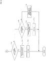
- FIG. 8 is a (first) flow chart showing a processing flow of a capacitor charge performance monitoring program.
- FIG. 9 is a (second) flow chart showing a processing flow of a capacitor charge performance monitoring program.
- component mounter 10 First, the configuration of component mounter 10 will be described with reference to FIG. 1 .
- At least one component mounter 10 is installed in a component mounting line, which is a production line for manufacturing a component-mounted board.
- Conveyor 13 that conveys circuit board 12 is provided on base 11 of component mounter 10 (below, the conveyance direction of circuit board 12 by conveyor 13 is referred to as the X direction, and the direction perpendicular to that is referred to as the Y direction).
- support member 15 a is fixed at a specified position, with the support member 15 b on the opposite side being adjusted in the Y direction along guide rail 16 by a screw mechanism (not shown) or the like such that the width of conveyor 13 (the gap between conveyor rails 13 a and 13 b ) is adjustable to the width of circuit board 12 .
- feeder setting table 22 is provided to the side of conveyor 13 on base 11 , with multiple feeders 23 being removably set on feeder setting table 22 in the Y direction.
- Set on each feeder 23 is a reel 24 on which is wound component supply tape housing many components at a fixed pitch, with the reel 24 being set such that the leading component of the component supply tape pulled from the reel 24 is positioned at a component pickup position (position at which the component is picked up by suction nozzle 25 ).
- Component mounter 10 is provided with head moving device 27 (refer to FIG. 2 ) for moving mounting head 26 in the following order: component pickup position—>component imaging position—>component mounting position.
- head moving device 27 for moving mounting head 26 in the following order: component pickup position—>component imaging position—>component mounting position.
- One or multiple suction nozzles 25 that pick up a component fed by a feeder to the component pickup position are held on mounting head 26 facing downwards, and the suction nozzle 25 is lowered and raised during component pickup operation and component mounting operation.
- component mounter 10 is provided with mark imaging camera 31 that is moved together with mounting head 24 and that images from above reference marks or the like provided on circuit board 12 , and component imaging camera 32 that images from below a component held by suction nozzle 25 .
- Component imaging camera 32 is fixed facing upwards in a space between conveyor 13 and feeder setting table 22 on base 11 .
- Each camera 31 , 32 is provided with a lighting device 33 , 34 , respectively, for illuminating an object to be imaged. The configuration of the lighting devices 33 , 34 will be described later.
- control device 40 of component mounter 10 connected to control device 40 of component mounter 10 are input device 41 such as a keyboard, mouse, or touch panel, memory device 42 such as a hard disk, RAM, or ROM that memorizes the capacitor charging performance monitoring program of FIGS. 8 and 9 that is described later and the like, and display device 43 such as an LCD display or CRT.
- input device 41 such as a keyboard, mouse, or touch panel
- memory device 42 such as a hard disk, RAM, or ROM that memorizes the capacitor charging performance monitoring program of FIGS. 8 and 9 that is described later and the like
- display device 43 such as an LCD display or CRT.
- Control device 40 of component mounter 10 is configured by one or multiple computers (CPUs), functions as a control section for controlling the operation of the respective functions of component mounter 10 , and also functions as an image processing section for processing an image captured by mark imaging camera 31 and component imaging camera 32 and recognizing a target object.
- CPUs computers
- Control device 40 of component mounter 10 uses mark imaging camera 31 to image from above reference marks of circuit board 12 that is clamped having been conveyed to a specified position by conveyor 13 and recognizes the reference marks, then measures each component mounting position on circuit board 12 based on the positions of the reference marks, and moves mounting head 26 in the order of component pickup position, component imaging position, component mounting position, causes suction nozzle 25 of mounting head 26 to pick up a component supplied by feeder 23 , uses component imaging camera 32 to image the component, and processes the captured image to recognize the shape of the component and measure the component shape data, then mounts the component after deciding the component mounting position of the component on circuit board 12 so as to correct the deviation of the component pickup position.
- the configuration of lighting devices 33 and 34 of cameras 31 and 32 is illustrated only by the configuration of lighting device 34 of component imaging camera 32 in FIG. 3 , and each of them includes power supply circuit 46 for supplying a power source of a specified DC voltage, light-emitting element 47 such as an LED or a flash lamp for generating illumination light, capacitor 48 such as an electrolytic capacitor charged by a current supplied from power supply circuit 46 , switching element 50 such as a transistor or a relay for turning on/off charging circuit 49 between power supply circuit 46 and capacitor 48 , and switching element 52 such as a transistor or a relay for turning on/off discharging circuit 51 between capacitor 48 and light-emitting element 47 , wherein the switching operation of each of the switching elements 50 and 52 is controlled by control device 40 of component mounter 10 as follows.
- Control device 40 of component mounter 10 performs control such that, before imaging of the target object, switching element 50 of charging circuit 49 is turned on to charge capacitor 48 in a state with switching element 52 of discharge circuit 51 turned off, and after charging is completed, switching element 50 of charging circuit 49 is turned off, then, when imaging is performed, switching element 52 of discharge circuit 51 is turned on to discharge the electric charge charged in capacitor 48 , making a large current flow in light-emitting element 47 such that light-emitting element 47 emits light with high brightness, and the imaging target is imaged by camera 31 , 32 while the imaging target is being illuminated.
- capacitor 48 only one capacitor 48 may be used, or multiple capacitors may be connected in parallel, in other words, the number of capacitors required to charge a specified amount of electric charge for generating the amount of illumination light necessary for image capturing (image recognition) of the imaging target may be connected in parallel. Further, when multiple light-emitting elements 47 are connected to discharge circuit 51 , they may be connected in series or in parallel.
- the amount of illumination light for illuminating the imaging target is insufficient due to the deterioration of capacitor 48 , such that the sharpness of the image captured by component imaging camera 32 is lowered, and the image recognition accuracy worsens.
- Such worsening of the image recognition accuracy also causes deterioration of the product quality due to deterioration of the component mounting accuracy, production of defective products by erroneous recognition, and stoppages of production due to an image processing error or the like.
- a capacitor charging performance monitoring system 55 for monitoring the charging performance of capacitor 48 of lighting device 34 of component imaging camera 32 is provided, and when capacitor 48 has deteriorated to a specified level, a warning regarding the deterioration of capacitor 48 is issued to the operator.
- capacitor charging performance monitoring system 55 will be described.
- Voltage detection resistor 56 for detecting the charging voltage of capacitor 48 is connected to charging circuit 49 of capacitor 48 , the potential between voltage detection resistor 56 and capacitor 48 is detected by charging voltage detecting section 57 as the charging voltage of capacitor 48 , and the detected value of the charging voltage is read into control device 40 of component mounter 10 .
- Control device 40 of component mounter 10 executes the capacitor charging performance monitoring program of FIGS.
- a charging time measuring section that measures, as a charging time, a time from starting charging to a time when a specified charging complete determination voltage that can be used to determine when the charging voltage of the capacitor 48 has reached full charge is reached based on the charging voltage of the capacitor 48 detected by charging voltage detecting section 57 , and also functions as a charging performance determining section configured to determine whether the capacitor 48 has deteriorated by determining whether the charging time measured by the charging time measuring section is equal to or less than specified deterioration threshold value B.
- the charging performance of capacitor 48 is such that the charging voltage of capacitor 48 rises exponentially with the time constant ⁇ as time elapses after the start of charging until finally matching the output voltage of power supply circuit 46 .
- control device 40 of component mounter 10 measures, as the charging time, a time from starting charging to a time when a specified charging complete determination voltage that can be used to determine when the charging voltage of the capacitor 48 has reached full charge is reached based on the charging voltage of the capacitor 48 detected by charging voltage detecting section 57 , and determines whether the capacitor 48 has deteriorated by determining whether the measured charging time is equal to or less than specified deterioration threshold value B (see FIGS. 4 and 5 ).
- the charging complete determination voltage may be set to, for example, a voltage of 90% of the power supply voltage V or a voltage slightly higher than that, or a voltage slightly lower than that, in short, may be set to a voltage at which it can be determined that charging is almost complete.
- the deterioration determination threshold value B may be set by any one of the following methods (1) to (3), for example.
- the measured charging time in the first operation after the installation of component mounter 10 in the component mounting line or in the first operation after the exchange of capacitor 48 is taken as a normal charging time, and deterioration determination threshold B is set to a time shorter than the normal charging time by a time corresponding to a predetermined deterioration amount.
- the time corresponding to the specified amount of deterioration may be, for example, a time corresponding to a specified percentage of the normal charging time.
- the charging time in a case of using a capacitor having the smallest capacitance in the product variation range of the capacitance of capacitor 48 is calculated as the normal charging time, and deterioration determination threshold B is set to a time shorter than the normal charging time by a time corresponding to a predetermined deterioration amount.
- the time corresponding to the specified amount of deterioration may be, for example, a time corresponding to a specified percentage of the normal charging time.
- the product specification data provided by the manufacturer or the like of capacitor 48 may be used as the product variation range of the capacitance of capacitor 48 .
- the setting of deterioration determination threshold B may be automatically performed by control device 40 of component mounter 10 using any of the methods (1) to (3) or the like, or an operator may calculate deterioration determination threshold B using any of the methods (1) to (3) or the like, and may store deterioration determination threshold B in memory device 42 by operating input device 41 .
- deterioration determination threshold value B may be calculated and stored in memory device 42 by the company that manufactures or sells component mounter 10 .
- control device 40 of component mounter 10 has, as a determination threshold value, in addition to deterioration determination threshold value B, connection error determination threshold value A that is smaller than deterioration determination threshold value B, and when the measured charging time is equal to or less than connection error determination threshold value A, it is determined that capacitor 48 cannot be normally charged due to a connection error of capacitor 48 , and a warning regarding this is issued.
- connection error determination threshold value A may be set to an appropriate value within a range of, for example, around several percent to around ten percent of deterioration determination threshold value B.
- control device 40 of component mounter 10 has, as a determination threshold value, in addition to deterioration determination threshold value B, charging error determination threshold value C that is larger than deterioration determination threshold value B, and when the measured charging time is equal to or less than charging error determination threshold value A, it is determined that capacitor 48 cannot be normally charged due to an error of power supply circuit 46 or an error of charging circuit 49 , and a warning regarding this is issued.
- charging error determination threshold value C may be set to an appropriate value within a range of about 1.5 to 3 times deterioration determination threshold value B, for example.
- control device 40 of component mounter 10 determines that capacitor 48 has deteriorated, has a connection error, or has a charging error, an operator is prompted to take measures such as replacing capacitor 48 by warning the operator using display or sound via display device 43 provided in component mounter 10 or a mobile terminal carried by the operator.
- the charging time of capacitor 48 need not be measured every time capacitor 48 is charged, and the charging time of capacitor 48 may be measured every time a predetermined period elapses, for example, every time the operating quantity of component mounter 10 or the number of times capacitor 48 has been charged reaches a predetermined value.
- the charging time of capacitor 48 may be measured when capacitor 48 is first charged every time component mounter 10 is operated. Accordingly, in a case in which capacitor 48 has deteriorated, has a connection error, or has a charging error, it can be detected at the start of production and a warning can be issued, and production can be started after the operator performs measures such as replacement of capacitor 48 in response to the warning.
- the charging time of capacitor 48 may be measured again when it is determined that capacitor 48 has deteriorated, has a connection error, or has a charging error, and as a result, if it is determined that capacitor 48 has deteriorated, has a connection error, or has a charging error again, the determination result may be confirmed and a warning issued. Accordingly, erroneous determination due to temporary noise or the like can be prevented, and the reliability of the determination result can be improved.
- the monitoring of the charging performance of capacitor 48 of the present embodiment described above is executed by control device 40 of component mounter 10 at predetermined intervals in accordance with the capacitor charging performance monitoring program of FIGS. 8 and 9 .
- the capacitor charging performance monitoring program of FIGS. 8 and 9 serves as a charging time measuring section and a charging performance determining section.
- step 101 it is determined whether it is time to measure the charging time of capacitor 48 .
- the time at which the charging time of capacitor 48 is measured is, for example, the time at which capacitor 48 is first charged every time component mounter 10 is operated, or every time a predetermined period elapses (for example, every time the operating quantity of component mounter 10 or the number of times capacitor 48 is charged reaches a predetermined value). If it is determined in step 101 that it is not time to measure the charging time of capacitor 48 , the program is terminated without performing subsequent processing.
- step 101 If it is determined in step 101 that it is time to measure the charging time of capacitor 48 , processing proceeds to step 102 to wait until the charging start timing of capacitor 48 . Then, when the charging start timing of capacitor 48 is reached, processing proceeds to step 103 , and measurement of the charging time of capacitor 48 is started.
- step 104 it is determined whether the charging voltage of capacitor 48 detected by charging voltage detecting section 57 has reached the charging complete determination voltage from which it can be determined that charging is complete, and if the charging complete determination voltage has not been reached, processing proceeds to step 105 , where it is determined whether the charging time of capacitor 48 has exceeded charging error determination threshold value C that is larger than deterioration determination threshold value B, and if charging error determination threshold value C is not exceeded, processing returns to step 104 .
- the measurement of the charging time of capacitor 48 is continued until the charging voltage of capacitor 48 detected by charging voltage detecting section 57 reaches the charging complete determination voltage within a range in which the charging time of capacitor 48 does not exceed charging error determination threshold value C.
- step 105 if the charging time of capacitor 48 exceeds charging error determination threshold value C, processing proceeds from step 105 to step 106 , and the measurement of the charging time of capacitor 48 is finished, and in step 107 , it is determined that capacitor 48 cannot be normally charged due to an error of power supply circuit 46 or an error of charging circuit 49 (charging error). In this case, processing proceeds to step 108 , where the operator is warned by display or sound of the determination result, and the program is terminated.
- step 104 determines whether the charging voltage of capacitor 48 is equal to or less than connection error determination threshold A that is smaller than deterioration determination threshold B.
- connection error determination threshold value A connection error determination threshold value A
- processing proceeds to step 111 , where it is determined that capacitor 48 cannot be normally charged due to a connection error of capacitor 48 , and in step 112 , the determination result is issued as a warning to the operator by display or sound, and the program ends.
- step 110 determines whether the charging time of capacitor 48 is not equal to or less than connection error determination threshold value A. If it is determined in step 110 that the charging time of capacitor 48 is not equal to or less than connection error determination threshold value A, processing proceeds to step 113 , and it is determined whether the charging time of capacitor 48 is equal to or less than deterioration determination threshold value B. As a result, if it is determined that the charging time of capacitor 48 is equal to or less than deterioration determination threshold value B, processing proceeds to step 114 , where it is determined that capacitor 48 has deteriorated, and in step 115 , a warning regarding the deterioration of capacitor 48 is issued to the operator by display or sound, and the program ends.
- step 113 determines whether the charging time of capacitor 48 is not equal to or less than deterioration determination threshold value B. If it is determined in step 113 that the charging time of capacitor 48 is not equal to or less than deterioration determination threshold value B, processing proceeds to step 116 , where it is determined that capacitor 48 has not deteriorated (normal), and the program ends.
- control device 40 of component mounter 10 measures the charging time of capacitor 48 and determines that capacitor 48 has deteriorated when the measured value becomes equal to or less than specified deterioration determination threshold B by taking advantage of the relationship that as capacitor 48 deteriorates due to long-term use, the capacitance of capacitor 48 decreases and the charging time from the beginning of charging capacitor 48 to the end of charging capacitor 48 becomes shorter, such that a warning regarding the deterioration of capacitor 48 can be issued to an operator when capacitor 48 deteriorates to a specified level, and the operator can be prompted to take measures such as replacing capacitor 48 before a problem occurs due to the deterioration of capacitor 48 .
- capacitor 48 As a result, it is possible to prevent problem due to deterioration of capacitor 48 , for example, worse product quality due to deterioration of image recognition accuracy, production of defective products due to erroneous recognition, production stoppages due to image processing errors, and the like.
- the charging performance of capacitor 48 is monitored only for lighting device 34 of component imaging camera 32 , but the charging performance of the capacitor may be monitored in the same manner for lighting device 33 of mark imaging camera 31 . Further, the charging performance of capacitors in electric circuits other than those of lighting devices 33 and 34 of cameras 31 and 32 may be monitored in the same manner.
- the charging performance of the capacitor may also be monitored in the same manner for the lighting device of a camera mounted on a mounting-related device such as an inspection device or a screen printing device installed in the component mounting line.
- the present disclosure may be implemented with various modifications within a range that does not deviate from the gist of the disclosure, such as a case where the charging performance of a capacitor may be monitored in the same manner for a capacitor in an electric circuit mounted in a production machine installed in a production line other than a component mounting line machine.
Landscapes
- Engineering & Computer Science (AREA)
- Power Engineering (AREA)
- Physics & Mathematics (AREA)
- General Physics & Mathematics (AREA)
- Testing Electric Properties And Detecting Electric Faults (AREA)
- Supply And Installment Of Electrical Components (AREA)
Applications Claiming Priority (1)
| Application Number | Priority Date | Filing Date | Title |
|---|---|---|---|
| PCT/JP2017/030263 WO2019038873A1 (ja) | 2017-08-24 | 2017-08-24 | 生産機械のコンデンサ充電性能監視システム |
Publications (2)
| Publication Number | Publication Date |
|---|---|
| US20210132159A1 US20210132159A1 (en) | 2021-05-06 |
| US11215680B2 true US11215680B2 (en) | 2022-01-04 |
Family
ID=65438443
Family Applications (1)
| Application Number | Title | Priority Date | Filing Date |
|---|---|---|---|
| US16/639,907 Active 2037-09-22 US11215680B2 (en) | 2017-08-24 | 2017-08-24 | Capacitor charging performance monitoring system of production machine |
Country Status (5)
| Country | Link |
|---|---|
| US (1) | US11215680B2 (de) |
| EP (1) | EP3674718B1 (de) |
| JP (1) | JP6875532B2 (de) |
| CN (1) | CN111033281A (de) |
| WO (1) | WO2019038873A1 (de) |
Families Citing this family (2)
| Publication number | Priority date | Publication date | Assignee | Title |
|---|---|---|---|---|
| WO2019077711A1 (ja) * | 2017-10-18 | 2019-04-25 | 日本たばこ産業株式会社 | バッテリユニット、香味吸引器、バッテリユニットを制御する方法、及びプログラム |
| CN114280377B (zh) * | 2021-12-10 | 2024-02-27 | 珠海格力电器股份有限公司 | 一种用于空调预充电回路检测电路的检测方法及空调 |
Citations (16)
| Publication number | Priority date | Publication date | Assignee | Title |
|---|---|---|---|---|
| JPH0521580B2 (de) * | 1985-10-16 | 1993-03-24 | Kontoron Insutsurumentsu Hoorudeingu Nv | |
| JPH05215800A (ja) | 1992-02-04 | 1993-08-24 | Toyota Autom Loom Works Ltd | コンデンサの劣化診断方法 |
| JP2002098725A (ja) | 2000-09-27 | 2002-04-05 | Fuji Electric Co Ltd | コンデンサの良否判定装置 |
| JP2004344946A (ja) | 2003-05-23 | 2004-12-09 | Aida Eng Ltd | プレス機械 |
| US20060087253A1 (en) | 2004-10-21 | 2006-04-27 | Nikon Corporation | Photographic illuminating device and camera |
| JP2007219148A (ja) | 2006-02-16 | 2007-08-30 | Canon Inc | ストロボを備えた光学機器 |
| US20070216425A1 (en) * | 2006-03-16 | 2007-09-20 | Power Systems Co., Ltd. | Capacitor apparatus |
| US20110221281A1 (en) * | 2010-03-11 | 2011-09-15 | Omron Corporation | Method for detecting capacity leakage of capacitor in power conditioner, power conditioner performing the same, and photovoltaic power system provided with the same |
| JP2013120741A (ja) | 2011-12-09 | 2013-06-17 | Iwasaki Electric Co Ltd | 閃光放電ランプ点灯装置及び光照射器 |
| WO2014076836A1 (ja) | 2012-11-19 | 2014-05-22 | 富士機械製造株式会社 | 部品実装機および実装検査機 |
| US9024592B2 (en) * | 2011-04-25 | 2015-05-05 | Samsung Electronics Co., Ltd. | Auxiliary power supply and user device including the auxiliary power supply |
| US9470739B2 (en) * | 2013-11-12 | 2016-10-18 | Ford Global Technologies, Llc | DC link capacitance measurement for electric vehicle drivetrain |
| US10114056B2 (en) * | 2016-03-25 | 2018-10-30 | Fujitsu Ten Limited | Deterioration specifying device and deterioration specifying method |
| US10161980B2 (en) * | 2015-02-27 | 2018-12-25 | Fujitsu Ten Limited | Deterioration detecting apparatus and deterioration detecting method |
| US10241144B2 (en) * | 2015-02-27 | 2019-03-26 | Fujitsu Ten Limited | Deterioration detecting apparatus and deterioration detecting method |
| US10627436B2 (en) * | 2016-12-21 | 2020-04-21 | SK Hynix Inc. | Capacitance sensing circuits |
Family Cites Families (7)
| Publication number | Priority date | Publication date | Assignee | Title |
|---|---|---|---|---|
| JPS63234867A (ja) * | 1987-03-20 | 1988-09-30 | Hitachi Ltd | インバ−タ装置の電源投入回路 |
| JP2653744B2 (ja) * | 1992-10-30 | 1997-09-17 | 富士通テン株式会社 | コンデンサの異常診断装置 |
| JP4095004B2 (ja) * | 2003-09-12 | 2008-06-04 | 株式会社リコー | 電源装置および画像形成装置 |
| JP2005354789A (ja) * | 2004-06-09 | 2005-12-22 | Hitachi Ltd | 電気車の制御装置 |
| JP4845613B2 (ja) * | 2006-07-05 | 2011-12-28 | 三菱電機エンジニアリング株式会社 | 電力用コンデンサ寿命診断機能付き充電装置 |
| JP5231892B2 (ja) * | 2008-08-04 | 2013-07-10 | 株式会社東芝 | 電気車用電源装置 |
| JP2011010518A (ja) * | 2009-06-29 | 2011-01-13 | Mitsubishi Electric Corp | 過給機の電動機制御装置 |
-
2017
- 2017-08-24 US US16/639,907 patent/US11215680B2/en active Active
- 2017-08-24 CN CN201780094206.7A patent/CN111033281A/zh active Pending
- 2017-08-24 JP JP2019537495A patent/JP6875532B2/ja active Active
- 2017-08-24 WO PCT/JP2017/030263 patent/WO2019038873A1/ja unknown
- 2017-08-24 EP EP17922424.1A patent/EP3674718B1/de active Active
Patent Citations (17)
| Publication number | Priority date | Publication date | Assignee | Title |
|---|---|---|---|---|
| JPH0521580B2 (de) * | 1985-10-16 | 1993-03-24 | Kontoron Insutsurumentsu Hoorudeingu Nv | |
| JPH05215800A (ja) | 1992-02-04 | 1993-08-24 | Toyota Autom Loom Works Ltd | コンデンサの劣化診断方法 |
| JP2002098725A (ja) | 2000-09-27 | 2002-04-05 | Fuji Electric Co Ltd | コンデンサの良否判定装置 |
| JP2004344946A (ja) | 2003-05-23 | 2004-12-09 | Aida Eng Ltd | プレス機械 |
| US20060087253A1 (en) | 2004-10-21 | 2006-04-27 | Nikon Corporation | Photographic illuminating device and camera |
| JP2006119350A (ja) | 2004-10-21 | 2006-05-11 | Nikon Corp | 撮影用照明装置およびカメラ |
| JP2007219148A (ja) | 2006-02-16 | 2007-08-30 | Canon Inc | ストロボを備えた光学機器 |
| US20070216425A1 (en) * | 2006-03-16 | 2007-09-20 | Power Systems Co., Ltd. | Capacitor apparatus |
| US20110221281A1 (en) * | 2010-03-11 | 2011-09-15 | Omron Corporation | Method for detecting capacity leakage of capacitor in power conditioner, power conditioner performing the same, and photovoltaic power system provided with the same |
| US9024592B2 (en) * | 2011-04-25 | 2015-05-05 | Samsung Electronics Co., Ltd. | Auxiliary power supply and user device including the auxiliary power supply |
| JP2013120741A (ja) | 2011-12-09 | 2013-06-17 | Iwasaki Electric Co Ltd | 閃光放電ランプ点灯装置及び光照射器 |
| WO2014076836A1 (ja) | 2012-11-19 | 2014-05-22 | 富士機械製造株式会社 | 部品実装機および実装検査機 |
| US9470739B2 (en) * | 2013-11-12 | 2016-10-18 | Ford Global Technologies, Llc | DC link capacitance measurement for electric vehicle drivetrain |
| US10161980B2 (en) * | 2015-02-27 | 2018-12-25 | Fujitsu Ten Limited | Deterioration detecting apparatus and deterioration detecting method |
| US10241144B2 (en) * | 2015-02-27 | 2019-03-26 | Fujitsu Ten Limited | Deterioration detecting apparatus and deterioration detecting method |
| US10114056B2 (en) * | 2016-03-25 | 2018-10-30 | Fujitsu Ten Limited | Deterioration specifying device and deterioration specifying method |
| US10627436B2 (en) * | 2016-12-21 | 2020-04-21 | SK Hynix Inc. | Capacitance sensing circuits |
Non-Patent Citations (2)
| Title |
|---|
| Extended European Search Report dated Jul. 16, 2020 in Patent Application No. 17922424.1, 8 pages. |
| International Search Report dated Nov. 7, 2017 in PCT/JP2017/030263 filed Aug. 24, 2017, 2 pages. |
Also Published As
| Publication number | Publication date |
|---|---|
| JP6875532B2 (ja) | 2021-05-26 |
| EP3674718B1 (de) | 2023-04-26 |
| WO2019038873A1 (ja) | 2019-02-28 |
| JPWO2019038873A1 (ja) | 2020-07-02 |
| US20210132159A1 (en) | 2021-05-06 |
| EP3674718A4 (de) | 2020-08-19 |
| CN111033281A (zh) | 2020-04-17 |
| EP3674718A1 (de) | 2020-07-01 |
Similar Documents
| Publication | Publication Date | Title |
|---|---|---|
| US10881041B2 (en) | Component mounting machine, feeder device, and splicing work defect determination method | |
| US11215680B2 (en) | Capacitor charging performance monitoring system of production machine | |
| US10609851B2 (en) | Mounter | |
| US20170280598A1 (en) | Component mounter | |
| EP3379913A1 (de) | Steuerungsvorrichtung für eine komponentenmontagemaschine | |
| CN108142000B (zh) | 基板作业系统及元件安装装置 | |
| US10499551B2 (en) | Electronic component mounting system | |
| CN103135520A (zh) | 电子元件安装系统 | |
| US11134597B2 (en) | Component mounting device | |
| US11064641B2 (en) | Component mounting machine | |
| JP6765756B2 (ja) | 部品実装機、部品認識方法 | |
| JP4921346B2 (ja) | 部品実装装置における吸着位置補正方法 | |
| JPH0685500A (ja) | 物品認識方法および同装置 | |
| CN106664818A (zh) | 电子元件安装机 | |
| JPWO2019064609A1 (ja) | 部品装着機 | |
| JP4913720B2 (ja) | 電子部品装着装置の電子部品装着方法 | |
| JP2013172062A (ja) | 実装装置、電子部品の良否判定方法、プログラム及び基板の製造方法 | |
| JP6578514B2 (ja) | 電子部品実装装置および電子部品実装方法 | |
| JP5592769B2 (ja) | 照明装置 | |
| US11412648B2 (en) | Component-mounting device | |
| US20220256751A1 (en) | Mounting device and method for controlling mounting device | |
| JP2010282536A (ja) | 画像処理方法及び画像処理装置 | |
| JP6641207B2 (ja) | 電子部品装着機及び生産ライン | |
| JP2016111152A (ja) | 部品実装装置 | |
| KR101510398B1 (ko) | 기판의 장착불량 원인 분석방법 |
Legal Events
| Date | Code | Title | Description |
|---|---|---|---|
| AS | Assignment |
Owner name: FUJI CORPORATION, JAPAN Free format text: ASSIGNMENT OF ASSIGNORS INTEREST;ASSIGNORS:OKI, HIDEAKI;OSAKI, SATOSHI;SIGNING DATES FROM 20190826 TO 20190920;REEL/FRAME:051846/0803 |
|
| FEPP | Fee payment procedure |
Free format text: ENTITY STATUS SET TO UNDISCOUNTED (ORIGINAL EVENT CODE: BIG.); ENTITY STATUS OF PATENT OWNER: LARGE ENTITY |
|
| STPP | Information on status: patent application and granting procedure in general |
Free format text: DOCKETED NEW CASE - READY FOR EXAMINATION |
|
| STPP | Information on status: patent application and granting procedure in general |
Free format text: NON FINAL ACTION MAILED |
|
| STPP | Information on status: patent application and granting procedure in general |
Free format text: RESPONSE TO NON-FINAL OFFICE ACTION ENTERED AND FORWARDED TO EXAMINER |
|
| STPP | Information on status: patent application and granting procedure in general |
Free format text: NOTICE OF ALLOWANCE MAILED -- APPLICATION RECEIVED IN OFFICE OF PUBLICATIONS |
|
| STPP | Information on status: patent application and granting procedure in general |
Free format text: PUBLICATIONS -- ISSUE FEE PAYMENT VERIFIED |
|
| STCF | Information on status: patent grant |
Free format text: PATENTED CASE |