US11128018B2 - Circuit body and battery module - Google Patents
Circuit body and battery module Download PDFInfo
- Publication number
- US11128018B2 US11128018B2 US16/506,617 US201916506617A US11128018B2 US 11128018 B2 US11128018 B2 US 11128018B2 US 201916506617 A US201916506617 A US 201916506617A US 11128018 B2 US11128018 B2 US 11128018B2
- Authority
- US
- United States
- Prior art keywords
- substrate
- conductor
- conductors
- battery
- connector
- Prior art date
- Legal status (The legal status is an assumption and is not a legal conclusion. Google has not performed a legal analysis and makes no representation as to the accuracy of the status listed.)
- Active, expires
Links
Images


Classifications
-
- H—ELECTRICITY
- H05—ELECTRIC TECHNIQUES NOT OTHERWISE PROVIDED FOR
- H05K—PRINTED CIRCUITS; CASINGS OR CONSTRUCTIONAL DETAILS OF ELECTRIC APPARATUS; MANUFACTURE OF ASSEMBLAGES OF ELECTRICAL COMPONENTS
- H05K1/00—Printed circuits
- H05K1/02—Details
- H05K1/11—Printed elements for providing electric connections to or between printed circuits
- H05K1/118—Printed elements for providing electric connections to or between printed circuits specially for flexible printed circuits, e.g. using folded portions
-
- H—ELECTRICITY
- H01—ELECTRIC ELEMENTS
- H01M—PROCESSES OR MEANS, e.g. BATTERIES, FOR THE DIRECT CONVERSION OF CHEMICAL ENERGY INTO ELECTRICAL ENERGY
- H01M50/00—Constructional details or processes of manufacture of the non-active parts of electrochemical cells other than fuel cells, e.g. hybrid cells
- H01M50/50—Current conducting connections for cells or batteries
- H01M50/502—Interconnectors for connecting terminals of adjacent batteries; Interconnectors for connecting cells outside a battery casing
-
- H—ELECTRICITY
- H01—ELECTRIC ELEMENTS
- H01M—PROCESSES OR MEANS, e.g. BATTERIES, FOR THE DIRECT CONVERSION OF CHEMICAL ENERGY INTO ELECTRICAL ENERGY
- H01M10/00—Secondary cells; Manufacture thereof
- H01M10/42—Methods or arrangements for servicing or maintenance of secondary cells or secondary half-cells
- H01M10/425—Structural combination with electronic components, e.g. electronic circuits integrated to the outside of the casing
-
- H—ELECTRICITY
- H01—ELECTRIC ELEMENTS
- H01M—PROCESSES OR MEANS, e.g. BATTERIES, FOR THE DIRECT CONVERSION OF CHEMICAL ENERGY INTO ELECTRICAL ENERGY
- H01M10/00—Secondary cells; Manufacture thereof
- H01M10/42—Methods or arrangements for servicing or maintenance of secondary cells or secondary half-cells
- H01M10/48—Accumulators combined with arrangements for measuring, testing or indicating the condition of cells, e.g. the level or density of the electrolyte
- H01M10/482—Accumulators combined with arrangements for measuring, testing or indicating the condition of cells, e.g. the level or density of the electrolyte for several batteries or cells simultaneously or sequentially
-
- H—ELECTRICITY
- H01—ELECTRIC ELEMENTS
- H01M—PROCESSES OR MEANS, e.g. BATTERIES, FOR THE DIRECT CONVERSION OF CHEMICAL ENERGY INTO ELECTRICAL ENERGY
- H01M50/00—Constructional details or processes of manufacture of the non-active parts of electrochemical cells other than fuel cells, e.g. hybrid cells
- H01M50/20—Mountings; Secondary casings or frames; Racks, modules or packs; Suspension devices; Shock absorbers; Transport or carrying devices; Holders
- H01M50/204—Racks, modules or packs for multiple batteries or multiple cells
- H01M50/207—Racks, modules or packs for multiple batteries or multiple cells characterised by their shape
- H01M50/209—Racks, modules or packs for multiple batteries or multiple cells characterised by their shape adapted for prismatic or rectangular cells
-
- H—ELECTRICITY
- H01—ELECTRIC ELEMENTS
- H01M—PROCESSES OR MEANS, e.g. BATTERIES, FOR THE DIRECT CONVERSION OF CHEMICAL ENERGY INTO ELECTRICAL ENERGY
- H01M50/00—Constructional details or processes of manufacture of the non-active parts of electrochemical cells other than fuel cells, e.g. hybrid cells
- H01M50/20—Mountings; Secondary casings or frames; Racks, modules or packs; Suspension devices; Shock absorbers; Transport or carrying devices; Holders
- H01M50/284—Mountings; Secondary casings or frames; Racks, modules or packs; Suspension devices; Shock absorbers; Transport or carrying devices; Holders with incorporated circuit boards, e.g. printed circuit boards [PCB]
-
- H—ELECTRICITY
- H01—ELECTRIC ELEMENTS
- H01M—PROCESSES OR MEANS, e.g. BATTERIES, FOR THE DIRECT CONVERSION OF CHEMICAL ENERGY INTO ELECTRICAL ENERGY
- H01M50/00—Constructional details or processes of manufacture of the non-active parts of electrochemical cells other than fuel cells, e.g. hybrid cells
- H01M50/20—Mountings; Secondary casings or frames; Racks, modules or packs; Suspension devices; Shock absorbers; Transport or carrying devices; Holders
- H01M50/298—Mountings; Secondary casings or frames; Racks, modules or packs; Suspension devices; Shock absorbers; Transport or carrying devices; Holders characterised by the wiring of battery packs
-
- H—ELECTRICITY
- H01—ELECTRIC ELEMENTS
- H01M—PROCESSES OR MEANS, e.g. BATTERIES, FOR THE DIRECT CONVERSION OF CHEMICAL ENERGY INTO ELECTRICAL ENERGY
- H01M50/00—Constructional details or processes of manufacture of the non-active parts of electrochemical cells other than fuel cells, e.g. hybrid cells
- H01M50/50—Current conducting connections for cells or batteries
- H01M50/502—Interconnectors for connecting terminals of adjacent batteries; Interconnectors for connecting cells outside a battery casing
- H01M50/519—Interconnectors for connecting terminals of adjacent batteries; Interconnectors for connecting cells outside a battery casing comprising printed circuit boards [PCB]
-
- H—ELECTRICITY
- H01—ELECTRIC ELEMENTS
- H01M—PROCESSES OR MEANS, e.g. BATTERIES, FOR THE DIRECT CONVERSION OF CHEMICAL ENERGY INTO ELECTRICAL ENERGY
- H01M50/00—Constructional details or processes of manufacture of the non-active parts of electrochemical cells other than fuel cells, e.g. hybrid cells
- H01M50/50—Current conducting connections for cells or batteries
- H01M50/569—Constructional details of current conducting connections for detecting conditions inside cells or batteries, e.g. details of voltage sensing terminals
-
- H—ELECTRICITY
- H05—ELECTRIC TECHNIQUES NOT OTHERWISE PROVIDED FOR
- H05K—PRINTED CIRCUITS; CASINGS OR CONSTRUCTIONAL DETAILS OF ELECTRIC APPARATUS; MANUFACTURE OF ASSEMBLAGES OF ELECTRICAL COMPONENTS
- H05K1/00—Printed circuits
- H05K1/02—Details
- H05K1/0277—Bendability or stretchability details
- H05K1/028—Bending or folding regions of flexible printed circuits
-
- H—ELECTRICITY
- H05—ELECTRIC TECHNIQUES NOT OTHERWISE PROVIDED FOR
- H05K—PRINTED CIRCUITS; CASINGS OR CONSTRUCTIONAL DETAILS OF ELECTRIC APPARATUS; MANUFACTURE OF ASSEMBLAGES OF ELECTRICAL COMPONENTS
- H05K3/00—Apparatus or processes for manufacturing printed circuits
- H05K3/36—Assembling printed circuits with other printed circuits
- H05K3/361—Assembling flexible printed circuits with other printed circuits
-
- H—ELECTRICITY
- H01—ELECTRIC ELEMENTS
- H01M—PROCESSES OR MEANS, e.g. BATTERIES, FOR THE DIRECT CONVERSION OF CHEMICAL ENERGY INTO ELECTRICAL ENERGY
- H01M10/00—Secondary cells; Manufacture thereof
- H01M10/42—Methods or arrangements for servicing or maintenance of secondary cells or secondary half-cells
- H01M10/425—Structural combination with electronic components, e.g. electronic circuits integrated to the outside of the casing
- H01M2010/4271—Battery management systems including electronic circuits, e.g. control of current or voltage to keep battery in healthy state, cell balancing
-
- H—ELECTRICITY
- H01—ELECTRIC ELEMENTS
- H01M—PROCESSES OR MEANS, e.g. BATTERIES, FOR THE DIRECT CONVERSION OF CHEMICAL ENERGY INTO ELECTRICAL ENERGY
- H01M2220/00—Batteries for particular applications
- H01M2220/20—Batteries in motive systems, e.g. vehicle, ship, plane
-
- H—ELECTRICITY
- H01—ELECTRIC ELEMENTS
- H01R—ELECTRICALLY-CONDUCTIVE CONNECTIONS; STRUCTURAL ASSOCIATIONS OF A PLURALITY OF MUTUALLY-INSULATED ELECTRICAL CONNECTING ELEMENTS; COUPLING DEVICES; CURRENT COLLECTORS
- H01R11/00—Individual connecting elements providing two or more spaced connecting locations for conductive members which are, or may be, thereby interconnected, e.g. end pieces for wires or cables supported by the wire or cable and having means for facilitating electrical connection to some other wire, terminal, or conductive member, blocks of binding posts
- H01R11/11—End pieces or tapping pieces for wires, supported by the wire and for facilitating electrical connection to some other wire, terminal or conductive member
- H01R11/28—End pieces consisting of a ferrule or sleeve
- H01R11/281—End pieces consisting of a ferrule or sleeve for connections to batteries
- H01R11/288—Interconnections between batteries
-
- Y—GENERAL TAGGING OF NEW TECHNOLOGICAL DEVELOPMENTS; GENERAL TAGGING OF CROSS-SECTIONAL TECHNOLOGIES SPANNING OVER SEVERAL SECTIONS OF THE IPC; TECHNICAL SUBJECTS COVERED BY FORMER USPC CROSS-REFERENCE ART COLLECTIONS [XRACs] AND DIGESTS
- Y02—TECHNOLOGIES OR APPLICATIONS FOR MITIGATION OR ADAPTATION AGAINST CLIMATE CHANGE
- Y02E—REDUCTION OF GREENHOUSE GAS [GHG] EMISSIONS, RELATED TO ENERGY GENERATION, TRANSMISSION OR DISTRIBUTION
- Y02E60/00—Enabling technologies; Technologies with a potential or indirect contribution to GHG emissions mitigation
- Y02E60/10—Energy storage using batteries
Definitions
- the present invention relates to a circuit body and a battery module.
- a battery module including a bus bar fixed to an electrode of each battery cell, a voltage detection line extending from the bus bar, and a connector for connecting the voltage detection line to an ECU is attached to a battery mounted in a hybrid car or an electric car.
- the ECU monitors the voltage of each battery cell detected through the voltage detection line of the battery module and adjusts the charge amount of the battery cell and the like.
- bus bars fixed to connection points are arranged at alternately separated positions.
- the voltage of the bus bars increases in order from one side of a circuit. Therefore, voltage detection lines extending from the bus bars to a connector are not arranged in the voltage order, which causes a circuit to be complicated by providing a circuit or the like which rearranges the voltage detection lines in the voltage order on an ECU side.
- the invention is made in view of the circumstances described above and an object thereof is to provide a circuit body and a battery module capable of arranging voltage detection lines in the voltage order to simplify a circuit.
- the invention provides a circuit body and a battery module having features that are described below in the form of configurations (1) to (4):
- the substrate includes
- a part of the substrate is overlapped in the connector connection portion, so an arrangement order of the other ends of the conductors corresponds to the potential order of the conductive members connected to the conductors.
- the substrate includes:
- a part of the second substrate is folded in the connector connection portion and overlapped on the first substrate, so an arrangement order of the other ends of the conductors included in the first substrate and the second substrate corresponds to the potential order of the conductive members connected to the conductors.
- the substrate includes a base portion and a folded portion folded with respect to the base portion, and
- the folded portion is folded in the connector connection portion and overlapped on the base portion, so an arrangement order of the other ends of the conductors included in the base portion and the folded portion corresponds to the potential order of the conductive members connected to the conductors.
- a battery module comprising:
- the circuit body configured as (1) described above, a part of the substrate is overlapped in the connector connection portion and the other ends of the conductors of which one ends are connected to respective bus bars are arranged in the connector connection portion in the potential order of the bus bars, that is, the voltage order of the battery assembly. Therefore, in the connector attached to the connector connection portion, the terminals are arranged in the voltage order of the battery assembly.
- the connector when connecting the connector to an ECU which monitors the voltage of the battery cell and adjusts the charge amount or the like, it is not necessary to provide a circuit or the like that rearranges the voltage detection lines in the voltage order on the ECU side, and thus the circuit can be simplified.
- the width of the connector connection portion can be adapted to the width of the connector.
- the circuit body configured as (2a) described above by folding a part of the second substrate and overlapping it on the first substrate, in the connector connection portion, the other ends of the conductors, one ends of which are connected to respective bus bars, can be arranged in the voltage order of the battery assembly.
- the conductors in the voltage order in the connector connection portion.
- circuit body configured as (3) described above, it is possible to arrange the other ends of the conductors, one ends of which are connected to respective bus bars, in the voltage order of the battery assembly, by folding the folded portion of the substrate and overlapping it on the base portion.
- the battery module configured as (4) described above, in the connector attached to the connector connection portion, terminals thereof are arranged in the voltage order of the battery assembly. Therefore, when connecting the connector to the ECU which monitors the voltage of the battery cell and adjusts the charge amount or the like, it is not necessary to provide a circuit or the like that rearranges the voltage detection lines in the voltage order on the ECU side, and thus the circuit can be simplified.
- FIG. 1 is a perspective view of a battery assembly in which a battery module according to a first embodiment is assembled
- FIG. 2 is a plan view of the battery assembly in which the battery module according to the first embodiment is assembled
- FIG. 3 is a plan view of a circuit body and a connector of the battery module
- FIG. 4 is a plan view of a first substrate and a second substrate constituting the circuit body
- FIGS. 5A to 5C are views illustrating a manufacturing process of the battery module, where FIGS. 5A to 5C are plan views of the first substrate and the second substrate, respectively;
- FIG. 6 is a perspective view of a battery assembly in which a battery module according to a second embodiment is assembled
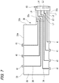
- FIG. 7 is a plan view of a circuit body and a connector of the battery module
- FIG. 8 is a plan view of a connector connection portion of a substrate constituting the circuit body
- FIG. 9 is a plan view of the connector connection portion and the connector of the substrate constituting the circuit body.
- FIGS. 10A and 10B are views illustrating a manufacturing process of the battery module, where FIGS. 10A and 10B are plan views of the substrate, respectively.
- FIG. 1 is a perspective view of a battery assembly in which the battery module according to the first embodiment is assembled.
- FIG. 2 is a plan view of the battery assembly in which the battery module according to the first embodiment is assembled.
- a battery module 10 according to the first embodiment is assembled to a battery assembly 1 .
- the battery assembly 1 is used, for example, as a power source of an electric car, a hybrid car, or the like.
- the battery assembly 1 is constituted of battery cells 2 composed of a plurality of secondary batteries.
- the battery cells 2 are stacked on one another to constitute a battery assembly 1 .
- Each battery cell 2 has a pair of electrodes 3 at the top.
- One of the pair of electrodes 3 is a positive electrode 3 A and the other is a negative electrode 3 B.
- the positive electrode 3 A and the negative electrode 3 B are disposed at mutually separated positions in each of the battery cells 2 .
- the battery cells 2 are arranged alternately such that the positive electrode 3 A and the negative electrode 3 B are adjacent to each other, that is, the positive electrode side and the negative electrode side of the adjacent battery cells 2 are in the opposite direction.
- the battery module 10 is assembled between the arrays of electrodes 3 at the top of the battery assembly 1 .
- the battery module 10 includes bus bars 20 A and 20 B, a circuit body 30 , and a connector 40 .
- the bus bars 20 A and 20 B are formed by pressing a plate made of a conductive metal material such as copper or copper alloy into a rectangular shape and each bus bar has a terminal insertion hole 21 . Further, the bus bars 20 A and 20 B are not limited to copper or copper alloy as long as they are conductive metal materials and may be made of, for example, aluminum or aluminum alloy.
- the bus bar 20 A has two terminal insertion holes 21 through which the positive electrode 3 A and the negative electrode 3 B are inserted and the bus bar 20 B has one terminal insertion hole 21 through which the positive electrode 3 A or the negative electrode 3 B is inserted.
- the adjacent positive electrode 3 A and negative electrode 3 B of two battery cells 2 are inserted into the terminal insertion holes 21 . Further, the bus bar 20 A is fastened to the positive electrode 3 A and the negative electrode 3 B by nuts (not illustrated) screwed into the positive electrode 3 A and the negative electrode 3 B. As a result, the adjacent positive electrode 3 A and negative electrode 3 B of two battery cells 2 are conducted by the bus bar 20 A. In the bus bars 20 B, the positive electrode 3 A and the negative electrode 3 B of two battery cells 2 disposed at end portions are inserted into the terminal insertion holes 21 .
- the bus bar 20 B is fastened to the positive electrode 3 A or the negative electrode 3 B by a nut (not illustrated) screwed into the positive electrode 3 A or the negative electrode 3 B.
- the battery cells 2 are connected in series by the bus bars 20 A and portions to which the bus bars 20 A and 20 B are fastened are taken as detection points P 1 to P 7 in order from the low potential side as points for detecting a voltage.
- FIG. 3 is a plan view of the circuit body and the connector of the battery module.
- FIG. 4 is a plan view of a first substrate and a second substrate constituting the circuit body.
- the circuit body 30 is constituted of a first substrate 31 and a second substrate 32 .
- the first substrate 31 and the second substrate 32 are flexible printed circuits (FPCs) each having a base 35 and a conductor 36 .
- the substrate 35 is constituted of a pair of flexible films bonded to each other and the conductor 36 made of a conductive metal foil is provided between the films.
- the first substrate 31 and the second substrate 32 have battery wiring portions 31 a and 32 a , connection portions 31 b and 32 b , and connector connection portions 31 c and 32 c .
- the battery wiring portions 31 a and 32 a are respectively routed along two rows of the arrays of the electrodes 3 at the top of the battery assembly 1 .
- connection port portions 41 protruding from edge portions and one end of the conductors 36 is drawn into each connection port portion 41 .
- connection port portions 41 there is no film on the upper side of the base 35 and one end of the conductor 36 is exposed on an upper surface.
- the bus bars 20 A and 20 B are overlapped and joined to the upper portions of those connection port portions 41 .
- the bus bars 20 A and 20 B and the conductor 36 are electrically connected.
- a method of joining the bus bars 20 A and 20 B in the connection port portion 41 for example, welding, caulking, fastening with a screw or the like may be used.
- connection port portion 41 one end of the conductor 36 may be exposed on a lower surface. In this case, the bus bars 20 A and 20 B are overlapped and joined to a lower portion of the connection port portion 41 .
- the battery wiring portion 31 a In the first substrate 31 , the battery wiring portion 31 a , the connection portion 31 b , and the connector connection portion 31 c are provided along the same direction.
- the conductors 36 of the first substrate 31 are voltage detection lines L 1 , L 3 , L 5 , and L 7 connected to the detection points P 1 , P 3 , P 5 , and P 7 .
- connection portion 32 b extends perpendicular to battery wiring portion 32 a and toward the first substrate 31 and the connector connection portion 32 c extends perpendicular to the connection portion 32 b and parallel to an extending direction of the first substrate 31 .
- the conductors 36 of the second substrate 32 are voltage detection lines L 2 , L 4 , and L 6 connected to the detection points P 2 , P 4 , and P 6 .
- the respective connector connection portions 31 c and 32 c are overlapped on each other. Further, portions where the connector connection portions 31 c and 32 c are overlapped are set as a connector connection end 30 a in the circuit body 30 .
- the voltage detection lines L 2 , L 4 , and L 6 of the second substrate 32 are arranged between the voltage detection lines L 1 , L 3 , L 5 , and L 7 of the first substrate 31 .
- the conductors 36 are arranged in the order of voltage detection lines L 1 to L 7 from one side. That is, in the connector connection end 30 a , the conductors 36 are arranged in the arrangement order of the battery cells 2 to be connected, that is, the order of voltage.
- the connector 40 is connected to the connector connection end 30 a of the circuit body 30 .
- the connector 40 is connected to an Electronic Control Unit (ECU) 5 (see FIGS. 1 and 2 ). Therefore, the voltage values of the voltage detection lines L 1 to L 7 of the circuit body 30 can be detected by the ECU 5 .
- ECU Electronic Control Unit
- the connector 40 for example, seven terminals (not illustrated) having press-contacting blades such as tuning fork-like terminals are provided at the top and bottom and those terminals are electrically connected to the conductors 36 of the voltage detection lines L 1 to L 7 by biting into the first substrate 31 and the second substrate 32 .
- the connector 40 four terminals provided on an upper side bite into the first substrate 31 from the upper surface and are electrically connected to the conductors 36 of the voltage detection lines L 1 , L 3 , L 5 , and L 7 and three terminals provided on a lower side bite into the second substrate 32 from a lower surface and are electrically connected to the conductors 36 of the voltage detection lines L 2 , L 4 , and L 6 .
- the connector 40 may be provided with terminals which bite into the conductors 36 of the voltage detection lines L 1 , L 3 , L 5 , and L 7 and the conductors 36 of the voltage detection lines L 2 , L 4 , and L 6 from inside the superposition of the connector connection portions 31 c and 32 c of the first substrate 31 and the second substrate 32 .
- FIGS. 5A to 5C are views illustrating a manufacturing process of the battery module, where FIGS. 5A to 5C are plan views of the first substrate and the second substrate, respectively.
- the first substrate 31 and the second substrate 32 formed of flexible circuit boards are formed.
- the second substrate 32 is formed in an L shape in which each of the connection portion 32 b and the connector connection portion 32 c is linear.
- the second substrate 32 is folded at a boundary between the connection portion 32 b and the connector connection portion 32 c and bent in a perpendicular direction to invert the connector connection portion 32 c.
- the connector connection portion 31 c of the first substrate 31 and the connector connection portion 32 c of the second substrate 32 are overlapped.
- the conductors 36 in the connector connection end 30 a of the circuit body 30 are arranged in the order of the voltage detection lines L 1 to L 7 which are in the order of potential.
- bus bars 20 A and 20 B are joined to the connection port portions 41 of the first substrate 31 and the second substrate 32 of the circuit body 30 and the connector 40 is attached to the connector connection end 30 a.
- the bus bars 20 A and 20 B are fixed to the electrodes 3 of the battery cells 2 of the battery assembly 1 by being fastened by nuts and the connector 40 is joined to the ECU 5 . Therefore, the ECU 5 detects the voltage of the battery cell 2 of the battery assembly 1 and monitors the voltage of each battery cell 2 to adjust the charge amount and the like.
- the battery module 10 of the first embodiment by folding a part of the second substrate 32 and overlapping it on the first substrate 31 , in connector connection portions 31 c and 32 c , the other ends of the conductors 36 , one ends of which are connected to respective bus bars 20 A and 20 B, are arranged in the order of voltage of the battery assembly. Therefore, in the connector 40 attached to the connector connection portions 31 c and 32 c , the terminals thereof are arranged in the order of voltage of the battery assembly 1 .
- the other ends of the conductors 36 can be arranged in the order of voltage of the battery assembly 1 in the connector connection portions 31 c and 32 c by folding a part of the second substrate 32 and overlapping it on the first substrate 31 . That is, with a simple structure, the conductors 36 can be arranged in the order of voltage in the connector connection portions 31 c and 32 c.
- the width of the connector connection end 30 a should be adapted to the width of the connector 40 regardless of the distance between the positive electrode 3 A and the negative electrode 3 B of the battery cells 2 .
- FIG. 6 is a perspective view of a battery assembly in which a battery module according to the second embodiment is assembled.
- FIG. 7 is a plan view of a circuit body and a connector of the battery module.
- the circuit body 30 is formed of a single substrate 33 .
- the substrate 33 is a flexible printed circuit (FPC) having a base 35 and a conductor 36 .
- FPC flexible printed circuit
- the substrate 33 has a battery wiring portion 33 a , a connection portion 33 b , and a connector connection portion 33 c .
- the battery wiring portion 33 a and the connection portion 33 b are formed to have substantially the same width and the connector connection portion 33 c is formed to be narrower than the battery wiring portion 33 a and the connection portion 33 b .
- the battery wiring portion 33 a is routed along the arrangement of the electrodes 3 at the top of the battery assembly 1 .
- the substrate 33 has connection port portions 41 connected to the bus bars 20 A and 20 B at both edges of the battery wiring portion 33 a and one end of the conductor 36 is drawn into each connection port portion 41 .
- the conductors 36 of the substrate 33 are the voltage detection lines L 1 , L 3 , L 5 , and L 7 connected to the detection points P 1 , P 3 , P 5 , and P 7 and the voltage detection lines L 2 , L 4 , and L 6 connected to the detection points P 2 , P 4 , and P 6 .
- FIG. 8 is a plan view of the connector connection portion of the substrate constituting the circuit body.
- FIG. 9 is a plan view of the connector connection portion and the connector of the substrate constituting the circuit body.
- the connector connection portion 33 c of the substrate 33 has a base portion 34 a and a folded portion 34 b .
- Each of the base portion 34 a and the folded portion 34 b has a width dimension about half that of the connection portion 33 b .
- the base portion 34 a is connected to the connection portion 33 b and the folded portion 34 b is connected to a side edge portion of the base portion 34 a .
- the voltage detection lines L 1 , L 3 , L 5 , and L 7 of the conductors 36 are arranged in the base portion 34 a and the voltage detection lines L 2 , L 4 , and L 6 of the conductors 36 are drawn in and arranged in the folded portion 34 b . As illustrated in FIG.
- the folded portion 34 b is folded and overlapped on the base portion 34 a . Further, by folding the folded portion 34 b and overlapping it on the base portion 34 a , the voltage detection lines L 2 , L 4 , and L 6 of the folded portion 34 b are disposed between the voltage detection lines L 1 , L 3 , L 5 , and L 7 of the base portion 34 a .
- the conductors 36 are arranged in the order of voltage detection lines L 1 to L 7 from one side. That is, in the connector connection end 30 a , the conductors 36 are arranged in the order of voltage.
- positioning holes H 1 and H 2 having a square hole shape and a round hole shape respectively are formed in the base portion 34 a and the folded portion 34 b and the positioning holes H 1 and the positioning holes H 2 respectively communicate by folding and overlapping the folded portion 34 b on the base portion 34 a.
- the connector 40 connected to the connector connection end 30 a has positioning pins P 1 and P 2 inserted into the positioning holes H 1 and H 2 .
- the connector 40 is positioned with high accuracy relative to the connector connection end 30 a by inserting the positioning pins P 1 and P 2 into the positioning holes H 1 and H 2 of the connector connection end 30 a of the circuit body 30 .
- the terminals of the connectors 40 are reliably electrically connected to the conductors 36 of the voltage detection lines L 1 to L 7 of the circuit body 30 .
- FIGS. 10A and 10B are views illustrating the manufacturing process of the battery module, where FIGS. 10A and 10B are plan views of the substrate, respectively.
- the substrate 33 made of a flexible circuit substrate is formed.
- a folded portion 34 b is formed by cutting away a part of the substrate 33 to form a slit portion 34 c.
- the folded portion 34 b is folded and overlapped on the base portion 34 a .
- the conductors 36 in the connector connection end 30 a of the circuit body 30 are arranged in order of the voltage detection lines L 1 to L 7 which is in order of potential.
- bus bars 20 A and 20 B are joined to the connection port portions 41 of the substrate 33 of the circuit body 30 and the connector 40 is attached to the connector connection end 30 a.
- the bus bars 20 A and 20 B are fixed to the electrodes 3 of the respective battery cells 2 of the battery assembly 1 by being fastened by nuts and the connector 40 is joined to the ECU 5 .
- the ECU 5 detects the voltage of the battery cell 2 of the battery assembly 1 and monitors the voltage of each battery cell 2 to adjust the charge amount or the like.
- the battery module 10 A of the second embodiment by folding and overlapping the folded portion 34 b of the substrate 33 on the base portion 34 a , the other ends of the conductors 36 , one ends of which are connected to respective bus bars 20 A and 20 B, can be arranged in the voltage order of the battery assembly 1 . That is, with the simplified structure, the conductors 36 can be arranged in the voltage order in the connector connection portion 33 c.
- each battery cell 2 constituting the battery module 10 is not limited to a rectangular shape as illustrated in FIG. 1 and the like and may be a cylindrical shape.
- the positive electrode and the negative electrode are arranged at both end portions in a cylinder axial direction of each battery cell 2 , for example, the first substrate 31 and the second substrate 32 are routed along respective end portions.
- the positive electrode 3 A and the negative electrode 3 B of the battery cell 2 are alternately arranged to be adjacent to each other in the battery module 10 is described as an example, but the invention is not limited thereto.
- the battery module 10 may be configured such that the positive electrodes 3 A and the negative electrodes 3 B of several adjacent battery cells 2 of a plurality of battery cells 2 are adjacent to each other, that is, several battery cells 2 are connected in parallel.
- the substrate (first substrate 31 , second substrate 32 , substrate 33 ) includes
- first substrate 31 , second substrate 32 , substrate 33 is overlapped in the connector connection portion ( 31 c , 32 c , 33 c ), so an arrangement order of the other ends of the conductors ( 36 ) corresponds to the potential order of the conductive members (bus bar 20 A, 20 B) connected to the conductors ( 36 ).
- the substrate includes:
- a part of the second substrate ( 32 ) is folded in the connector connection portion ( 31 c , 32 c ) and overlapped on the first substrate ( 31 ), so an arrangement order of the other ends of the conductors ( 36 ) included in the first substrate ( 31 ) and the second substrate ( 32 ) corresponds to the potential order of the conductive members (bus bar 20 A, 20 B) connected to the conductors ( 36 ).
- the substrate ( 33 ) includes a base portion ( 34 a ) and a folded portion ( 34 b ) folded with respect to the base portion ( 34 a ), and
- the folded portion ( 34 b ) is folded in the connector connection portion ( 33 c ) and overlapped on the base portion ( 34 a ), so an arrangement order of the other ends of the conductors ( 36 ) included in the base portion ( 34 a ) and the folded portion ( 34 b ) corresponds to the potential order of the conductive members (bus bar 20 A, 20 B) connected to the conductors ( 36 ).
- bus bar 20 A, 20 B connected to one end of a conductor ( 36 ) constituting the circuit body
- a connector ( 40 ) connected to the other end of the conductor ( 36 ).
Applications Claiming Priority (3)
| Application Number | Priority Date | Filing Date | Title |
|---|---|---|---|
| JP2018133502A JP7025297B2 (ja) | 2018-07-13 | 2018-07-13 | 回路体及び電池モジュール |
| JPJP2018-133502 | 2018-07-13 | ||
| JP2018-133502 | 2018-07-13 |
Publications (2)
| Publication Number | Publication Date |
|---|---|
| US20200020919A1 US20200020919A1 (en) | 2020-01-16 |
| US11128018B2 true US11128018B2 (en) | 2021-09-21 |
Family
ID=67253699
Family Applications (1)
| Application Number | Title | Priority Date | Filing Date |
|---|---|---|---|
| US16/506,617 Active 2040-02-20 US11128018B2 (en) | 2018-07-13 | 2019-07-09 | Circuit body and battery module |
Country Status (4)
| Country | Link |
|---|---|
| US (1) | US11128018B2 (ja) |
| EP (1) | EP3595038B1 (ja) |
| JP (1) | JP7025297B2 (ja) |
| CN (1) | CN110718661B (ja) |
Families Citing this family (8)
| Publication number | Priority date | Publication date | Assignee | Title |
|---|---|---|---|---|
| JP6837033B2 (ja) * | 2018-06-27 | 2021-03-03 | 矢崎総業株式会社 | 電池モジュール |
| JP6774460B2 (ja) * | 2018-07-13 | 2020-10-21 | 矢崎総業株式会社 | 回路体及び電池モジュール |
| JP2021125405A (ja) * | 2020-02-06 | 2021-08-30 | 日本メクトロン株式会社 | フレキシブルプリント配線板及びバッテリモジュール |
| JPWO2021199489A1 (ja) * | 2020-03-30 | 2021-10-07 | ||
| KR102580241B1 (ko) * | 2020-10-13 | 2023-09-19 | 삼성에스디아이 주식회사 | 배터리 팩 |
| JP2022144921A (ja) * | 2021-03-19 | 2022-10-03 | 株式会社オートネットワーク技術研究所 | 配線モジュール |
| JP2022144922A (ja) * | 2021-03-19 | 2022-10-03 | 株式会社オートネットワーク技術研究所 | 配線モジュール |
| WO2023130144A1 (en) * | 2022-01-03 | 2023-07-06 | Cps Technology Holdings Llc | Intelligent battery and assembly method |
Citations (11)
| Publication number | Priority date | Publication date | Assignee | Title |
|---|---|---|---|---|
| JP2002298958A (ja) | 2001-03-30 | 2002-10-11 | Olympus Optical Co Ltd | フレキシブル基板、及び、基板接続用コネクタ |
| JP2003323923A (ja) | 2002-02-28 | 2003-11-14 | Sumitomo Electric Ind Ltd | フラットケーブルと電子部品との接続構造 |
| JP2011210711A (ja) | 2010-03-12 | 2011-10-20 | Autonetworks Technologies Ltd | 電池モジュール |
| US20120019061A1 (en) | 2009-03-31 | 2012-01-26 | Sanyo Electric Co., Ltd. | Battery module, battery system and electric vehicle |
| JP2012226969A (ja) | 2011-04-19 | 2012-11-15 | Jst Mfg Co Ltd | 電池モジュールのハーネス及び電池モジュール |
| US20120328920A1 (en) | 2010-03-12 | 2012-12-27 | Autonetworks Technologies, Ltd. | Battery module |
| CN204809296U (zh) | 2015-07-21 | 2015-11-25 | 苏州安靠电源有限公司 | 电池组采样装置 |
| US20170025661A1 (en) * | 2015-07-23 | 2017-01-26 | Ford Global Technologies, Llc | Sensor lead securing assembly and method |
| US20170133724A1 (en) * | 2014-06-26 | 2017-05-11 | Robert Bosch Gmbh | Transmitting device for transmitting electrical signals from at least one galvanic cell to at least one electronic evaluating unit |
| US20170318663A1 (en) | 2016-04-27 | 2017-11-02 | Yazaki Corporation | Printed circuit body |
| US10601017B2 (en) * | 2017-08-04 | 2020-03-24 | Yazaki Corporation | Conductor module |
Family Cites Families (3)
| Publication number | Priority date | Publication date | Assignee | Title |
|---|---|---|---|---|
| JP5194584B2 (ja) * | 2006-11-27 | 2013-05-08 | 日産自動車株式会社 | 配線基板、及び積層型蓄電デバイス |
| KR20120073195A (ko) * | 2009-08-31 | 2012-07-04 | 산요덴키가부시키가이샤 | 배터리 모듈, 배터리 시스템 및 전동 차량 |
| JP6249991B2 (ja) * | 2015-06-10 | 2017-12-20 | 矢崎総業株式会社 | 配線モジュール |
-
2018
- 2018-07-13 JP JP2018133502A patent/JP7025297B2/ja active Active
-
2019
- 2019-07-09 US US16/506,617 patent/US11128018B2/en active Active
- 2019-07-10 CN CN201910618847.9A patent/CN110718661B/zh active Active
- 2019-07-11 EP EP19185620.2A patent/EP3595038B1/en active Active
Patent Citations (12)
| Publication number | Priority date | Publication date | Assignee | Title |
|---|---|---|---|---|
| JP2002298958A (ja) | 2001-03-30 | 2002-10-11 | Olympus Optical Co Ltd | フレキシブル基板、及び、基板接続用コネクタ |
| JP2003323923A (ja) | 2002-02-28 | 2003-11-14 | Sumitomo Electric Ind Ltd | フラットケーブルと電子部品との接続構造 |
| US20120019061A1 (en) | 2009-03-31 | 2012-01-26 | Sanyo Electric Co., Ltd. | Battery module, battery system and electric vehicle |
| JP2011210711A (ja) | 2010-03-12 | 2011-10-20 | Autonetworks Technologies Ltd | 電池モジュール |
| US20120328920A1 (en) | 2010-03-12 | 2012-12-27 | Autonetworks Technologies, Ltd. | Battery module |
| JP2012226969A (ja) | 2011-04-19 | 2012-11-15 | Jst Mfg Co Ltd | 電池モジュールのハーネス及び電池モジュール |
| US20170133724A1 (en) * | 2014-06-26 | 2017-05-11 | Robert Bosch Gmbh | Transmitting device for transmitting electrical signals from at least one galvanic cell to at least one electronic evaluating unit |
| CN204809296U (zh) | 2015-07-21 | 2015-11-25 | 苏州安靠电源有限公司 | 电池组采样装置 |
| US20170025661A1 (en) * | 2015-07-23 | 2017-01-26 | Ford Global Technologies, Llc | Sensor lead securing assembly and method |
| US20170318663A1 (en) | 2016-04-27 | 2017-11-02 | Yazaki Corporation | Printed circuit body |
| JP2017199804A (ja) | 2016-04-27 | 2017-11-02 | 矢崎総業株式会社 | 印刷回路体 |
| US10601017B2 (en) * | 2017-08-04 | 2020-03-24 | Yazaki Corporation | Conductor module |
Also Published As
| Publication number | Publication date |
|---|---|
| US20200020919A1 (en) | 2020-01-16 |
| JP7025297B2 (ja) | 2022-02-24 |
| CN110718661B (zh) | 2022-07-29 |
| JP2020013829A (ja) | 2020-01-23 |
| EP3595038A1 (en) | 2020-01-15 |
| CN110718661A (zh) | 2020-01-21 |
| EP3595038B1 (en) | 2021-12-22 |
Similar Documents
| Publication | Publication Date | Title |
|---|---|---|
| US11128018B2 (en) | Circuit body and battery module | |
| US11063322B2 (en) | Circuit body and battery module | |
| US10629873B2 (en) | Bus bar module and battery pack | |
| US10586970B2 (en) | Wiring module | |
| US11211727B2 (en) | Connector-attached circuit body and bus bar module | |
| JP6227082B1 (ja) | 接続モジュール | |
| JP2012190678A (ja) | 蓄電ユニット用のバスバーモジュール | |
| US9184472B2 (en) | Battery pack and method of manufacturing battery pack with interconnected half contact pads | |
| JP2021068696A (ja) | 配線モジュール及び蓄電モジュール | |
| US20240014517A1 (en) | Wiring module | |
| US20240014501A1 (en) | Wiring module | |
| US20220006159A1 (en) | Connection module | |
| US11602050B2 (en) | Flexible printed circuit board and wiring module | |
| US20230231259A1 (en) | Battery wiring module | |
| US20200395589A1 (en) | Circuit body, connection structure of a board and a circuit body, and busbar module | |
| US20230395878A1 (en) | Battery monitoring module and flexible printed wiring board | |
| US11757159B2 (en) | Conductive module | |
| WO2023037889A1 (ja) | 配線モジュール | |
| US20220263141A1 (en) | Wiring module | |
| US20240128614A1 (en) | Flexible wiring component | |
| JP2024033130A (ja) | 電池パック | |
| JP2023103074A (ja) | 配線板組立体 |
Legal Events
| Date | Code | Title | Description |
|---|---|---|---|
| AS | Assignment |
Owner name: YAZAKI CORPORATION, JAPAN Free format text: ASSIGNMENT OF ASSIGNORS INTEREST;ASSIGNOR:MAKINO, KIMITOSHI;REEL/FRAME:049703/0271 Effective date: 20190618 |
|
| FEPP | Fee payment procedure |
Free format text: ENTITY STATUS SET TO UNDISCOUNTED (ORIGINAL EVENT CODE: BIG.); ENTITY STATUS OF PATENT OWNER: LARGE ENTITY |
|
| STPP | Information on status: patent application and granting procedure in general |
Free format text: APPLICATION DISPATCHED FROM PREEXAM, NOT YET DOCKETED |
|
| STPP | Information on status: patent application and granting procedure in general |
Free format text: DOCKETED NEW CASE - READY FOR EXAMINATION |
|
| STPP | Information on status: patent application and granting procedure in general |
Free format text: NON FINAL ACTION MAILED |
|
| STPP | Information on status: patent application and granting procedure in general |
Free format text: NOTICE OF ALLOWANCE MAILED -- APPLICATION RECEIVED IN OFFICE OF PUBLICATIONS |
|
| STPP | Information on status: patent application and granting procedure in general |
Free format text: PUBLICATIONS -- ISSUE FEE PAYMENT RECEIVED |
|
| STCF | Information on status: patent grant |
Free format text: PATENTED CASE |
|
| AS | Assignment |
Owner name: YAZAKI CORPORATION, JAPAN Free format text: CHANGE OF ADDRESS;ASSIGNOR:YAZAKI CORPORATION;REEL/FRAME:063845/0802 Effective date: 20230331 |