US11053444B2 - Method and system for optimizing coke plant operation and output - Google Patents
Method and system for optimizing coke plant operation and output Download PDFInfo
- Publication number
- US11053444B2 US11053444B2 US16/251,352 US201916251352A US11053444B2 US 11053444 B2 US11053444 B2 US 11053444B2 US 201916251352 A US201916251352 A US 201916251352A US 11053444 B2 US11053444 B2 US 11053444B2
- Authority
- US
- United States
- Prior art keywords
- coal
- coke oven
- coking
- charging
- charge
- Prior art date
- Legal status (The legal status is an assumption and is not a legal conclusion. Google has not performed a legal analysis and makes no representation as to the accuracy of the status listed.)
- Active
Links
Images


Classifications
-
- C—CHEMISTRY; METALLURGY
- C10—PETROLEUM, GAS OR COKE INDUSTRIES; TECHNICAL GASES CONTAINING CARBON MONOXIDE; FUELS; LUBRICANTS; PEAT
- C10B—DESTRUCTIVE DISTILLATION OF CARBONACEOUS MATERIALS FOR PRODUCTION OF GAS, COKE, TAR, OR SIMILAR MATERIALS
- C10B15/00—Other coke ovens
- C10B15/02—Other coke ovens with floor heating
-
- C—CHEMISTRY; METALLURGY
- C10—PETROLEUM, GAS OR COKE INDUSTRIES; TECHNICAL GASES CONTAINING CARBON MONOXIDE; FUELS; LUBRICANTS; PEAT
- C10B—DESTRUCTIVE DISTILLATION OF CARBONACEOUS MATERIALS FOR PRODUCTION OF GAS, COKE, TAR, OR SIMILAR MATERIALS
- C10B21/00—Heating of coke ovens with combustible gases
- C10B21/10—Regulating and controlling the combustion
- C10B21/12—Burners
-
- C—CHEMISTRY; METALLURGY
- C10—PETROLEUM, GAS OR COKE INDUSTRIES; TECHNICAL GASES CONTAINING CARBON MONOXIDE; FUELS; LUBRICANTS; PEAT
- C10B—DESTRUCTIVE DISTILLATION OF CARBONACEOUS MATERIALS FOR PRODUCTION OF GAS, COKE, TAR, OR SIMILAR MATERIALS
- C10B25/00—Doors or closures for coke ovens
- C10B25/02—Doors; Door frames
-
- C—CHEMISTRY; METALLURGY
- C10—PETROLEUM, GAS OR COKE INDUSTRIES; TECHNICAL GASES CONTAINING CARBON MONOXIDE; FUELS; LUBRICANTS; PEAT
- C10B—DESTRUCTIVE DISTILLATION OF CARBONACEOUS MATERIALS FOR PRODUCTION OF GAS, COKE, TAR, OR SIMILAR MATERIALS
- C10B31/00—Charging devices
-
- C—CHEMISTRY; METALLURGY
- C10—PETROLEUM, GAS OR COKE INDUSTRIES; TECHNICAL GASES CONTAINING CARBON MONOXIDE; FUELS; LUBRICANTS; PEAT
- C10B—DESTRUCTIVE DISTILLATION OF CARBONACEOUS MATERIALS FOR PRODUCTION OF GAS, COKE, TAR, OR SIMILAR MATERIALS
- C10B31/00—Charging devices
- C10B31/02—Charging devices for charging vertically
-
- C—CHEMISTRY; METALLURGY
- C10—PETROLEUM, GAS OR COKE INDUSTRIES; TECHNICAL GASES CONTAINING CARBON MONOXIDE; FUELS; LUBRICANTS; PEAT
- C10B—DESTRUCTIVE DISTILLATION OF CARBONACEOUS MATERIALS FOR PRODUCTION OF GAS, COKE, TAR, OR SIMILAR MATERIALS
- C10B31/00—Charging devices
- C10B31/06—Charging devices for charging horizontally
- C10B31/08—Charging devices for charging horizontally coke ovens with horizontal chambers
- C10B31/10—Charging devices for charging horizontally coke ovens with horizontal chambers with one compact charge
-
- C—CHEMISTRY; METALLURGY
- C10—PETROLEUM, GAS OR COKE INDUSTRIES; TECHNICAL GASES CONTAINING CARBON MONOXIDE; FUELS; LUBRICANTS; PEAT
- C10B—DESTRUCTIVE DISTILLATION OF CARBONACEOUS MATERIALS FOR PRODUCTION OF GAS, COKE, TAR, OR SIMILAR MATERIALS
- C10B35/00—Combined charging and discharging devices
-
- C—CHEMISTRY; METALLURGY
- C10—PETROLEUM, GAS OR COKE INDUSTRIES; TECHNICAL GASES CONTAINING CARBON MONOXIDE; FUELS; LUBRICANTS; PEAT
- C10B—DESTRUCTIVE DISTILLATION OF CARBONACEOUS MATERIALS FOR PRODUCTION OF GAS, COKE, TAR, OR SIMILAR MATERIALS
- C10B37/00—Mechanical treatments of coal charges in the oven
- C10B37/02—Levelling charges, e.g. with bars
-
- C—CHEMISTRY; METALLURGY
- C10—PETROLEUM, GAS OR COKE INDUSTRIES; TECHNICAL GASES CONTAINING CARBON MONOXIDE; FUELS; LUBRICANTS; PEAT
- C10B—DESTRUCTIVE DISTILLATION OF CARBONACEOUS MATERIALS FOR PRODUCTION OF GAS, COKE, TAR, OR SIMILAR MATERIALS
- C10B37/00—Mechanical treatments of coal charges in the oven
- C10B37/04—Compressing charges
-
- C—CHEMISTRY; METALLURGY
- C10—PETROLEUM, GAS OR COKE INDUSTRIES; TECHNICAL GASES CONTAINING CARBON MONOXIDE; FUELS; LUBRICANTS; PEAT
- C10B—DESTRUCTIVE DISTILLATION OF CARBONACEOUS MATERIALS FOR PRODUCTION OF GAS, COKE, TAR, OR SIMILAR MATERIALS
- C10B39/00—Cooling or quenching coke
- C10B39/04—Wet quenching
- C10B39/06—Wet quenching in the oven
-
- C—CHEMISTRY; METALLURGY
- C10—PETROLEUM, GAS OR COKE INDUSTRIES; TECHNICAL GASES CONTAINING CARBON MONOXIDE; FUELS; LUBRICANTS; PEAT
- C10B—DESTRUCTIVE DISTILLATION OF CARBONACEOUS MATERIALS FOR PRODUCTION OF GAS, COKE, TAR, OR SIMILAR MATERIALS
- C10B41/00—Safety devices, e.g. signalling or controlling devices for use in the discharge of coke
-
- C—CHEMISTRY; METALLURGY
- C10—PETROLEUM, GAS OR COKE INDUSTRIES; TECHNICAL GASES CONTAINING CARBON MONOXIDE; FUELS; LUBRICANTS; PEAT
- C10B—DESTRUCTIVE DISTILLATION OF CARBONACEOUS MATERIALS FOR PRODUCTION OF GAS, COKE, TAR, OR SIMILAR MATERIALS
- C10B5/00—Coke ovens with horizontal chambers
-
- C—CHEMISTRY; METALLURGY
- C10—PETROLEUM, GAS OR COKE INDUSTRIES; TECHNICAL GASES CONTAINING CARBON MONOXIDE; FUELS; LUBRICANTS; PEAT
- C10B—DESTRUCTIVE DISTILLATION OF CARBONACEOUS MATERIALS FOR PRODUCTION OF GAS, COKE, TAR, OR SIMILAR MATERIALS
- C10B57/00—Other carbonising or coking processes; Features of destructive distillation processes in general
- C10B57/02—Multi-step carbonising or coking processes
-
- C—CHEMISTRY; METALLURGY
- C10—PETROLEUM, GAS OR COKE INDUSTRIES; TECHNICAL GASES CONTAINING CARBON MONOXIDE; FUELS; LUBRICANTS; PEAT
- C10B—DESTRUCTIVE DISTILLATION OF CARBONACEOUS MATERIALS FOR PRODUCTION OF GAS, COKE, TAR, OR SIMILAR MATERIALS
- C10B57/00—Other carbonising or coking processes; Features of destructive distillation processes in general
- C10B57/08—Non-mechanical pretreatment of the charge, e.g. desulfurization
-
- C—CHEMISTRY; METALLURGY
- C10—PETROLEUM, GAS OR COKE INDUSTRIES; TECHNICAL GASES CONTAINING CARBON MONOXIDE; FUELS; LUBRICANTS; PEAT
- C10B—DESTRUCTIVE DISTILLATION OF CARBONACEOUS MATERIALS FOR PRODUCTION OF GAS, COKE, TAR, OR SIMILAR MATERIALS
- C10B15/00—Other coke ovens
Definitions
- the present technology is generally directed to optimizing the operation and output of coke plants.
- Coke is a solid carbon fuel and carbon source used to melt and reduce iron ore in the production of steel.
- coke is produced by batch feeding pulverized coal to an oven that is sealed and heated to very high temperatures for approximately forty-eight hours under closely-controlled atmospheric conditions.
- Coking ovens have been used for many years to convert coal into metallurgical coke.
- finely crushed coal is heated under controlled temperature conditions to devolatilize the coal and form a fused mass of coke having a predetermined porosity and strength. Because the production of coke is a batch process, multiple coke ovens are operated simultaneously.
- a pusher charger machine (“PCM”) is typically used on the coal side of the oven for a number of different operations.
- a common PCM operation sequence begins as the PCM is moved along a set of rails that run in front of an oven battery to an assigned oven and align a coal charging system of the PCM with the oven.
- the pusher side oven door is removed from the oven using a door extractor from the coal charging system.
- the PCM is then moved to align a pusher ram of the PCM to the center of the oven.
- the pusher ram is energized, to push coke from the oven interior.
- the PCM is again moved away from the oven center to align the coal charging system with the oven center.
- Coal is delivered to the coal charging system of the PCM by a tripper conveyor.
- the coal charging system then charges the coal into the oven interior.
- particulate matter entrained in hot gas emissions that escape from the oven face are captured by the PCM during the step of charging the coal.
- the particulate matter is drawn into an emissions hood through the baghouse of a dust collector.
- the charging conveyor is then retracted from the oven. Finally, the door extractor of the PCM replaces and latches the pusher side oven door.
- PCM coal charging systems 10 have commonly included an elongated frame 12 that is mounted on the PCM (not depicted) and reciprocally movable, toward and away from the coke ovens.
- a planar charging head 14 is positioned at a free distal end of the elongated frame 12 .
- a conveyor 16 is positioned within the elongated frame 12 and substantially extends along a length of the elongated frame 12 .
- the charging head 14 is used, in a reciprocal motion, to generally level the coal that is deposited in the oven.
- FIGS. 2A, 3A, and 4A the prior art coal charging systems tend to leave voids 16 at the sides of the coal bed, as shown in FIG.
- FIG. 2A depicts the manner in which an ideally charged, level coke bed would look.
- the weight of coal charging system 10 which can include internal water cooling systems, can be 80,000 pounds or more.
- the coal charging system 10 deflects downwardly at its free distal end. This shortens the coal charge capacity.
- FIG. 3A indicates the drop in bed height caused by the deflections of the coal charging system 10 .
- the plot depicted in FIG. 5 shows the coal bed profile along the oven length.
- the bed height drop, due to coal charging system deflection is from five inches to eight inches between the pusher side to the coke side, depending upon the charge weight. As depicted, the effect of the deflection is more significant when less coal is charged into the oven. In general, coal charging system deflection can cause a coal volume loss of approximately one to two tons.
- FIG. 3B depicts the manner in which an ideally charged, level coke bed would look.
- the coal charging system 10 provides little benefit in the way of coal bed densification.
- the coal charging system 10 provides minimal improvement to internal coal bed density, forming a first layer d 1 and a second, less dense layer d 2 at the bottom of the coal bed.
- Increasing the density of the coal bed can facilitate conductive heat transfer throughout the coal bed which is a component in determining oven cycle time and oven production capacity.
- FIG. 6 depicts a set of density measurements taken for an oven test using a prior art coal charging system 10 .
- the line with diamond indicators shows the density on the coal bed surface.
- FIG. 4B depicts the manner in which an ideally charged, level coke bed would look, having relatively increased density layers D 1 and D 2 .
- Typical coking operations present coke ovens that coke an average of forty-seven tons of coal in a forty-eight hour period. Accordingly, such ovens are said to process coal at a rate of approximately 0.98 tons/hr, by previously known methods of oven charging and operation.
- Several factors contribute to the coal processing rate, including the constraints of draft, oven temperature (gas temperature and thermal reserve from the oven brick), and operating temperature limits of the oven sole flue, common tunnel, and associated components, such as Heat Recovery Steam Generators (HRSG). Accordingly, it has heretofore been difficult to attain coal processing rates that exceed 1.0 tons/hr.
- FIG. 1 depicts a front perspective view of a prior art coal charging system.
- FIG. 2A depicts a front view of a coal bed that was charged into a coke oven using a prior art coal charging system and depicts that the coal bed is not level, having voids at the sides of the bed.
- FIG. 2B depicts a front view of a coal bed that was ideally charged into a coke oven, without voids at the sides of the bed.
- FIG. 3A depicts a side elevation view of a coal bed that was charged into a coke oven using a prior art coal charging system and depicts that the coal bed is not level, having voids at the end portions of the bed.
- FIG. 3B depicts a side elevation view of a coal bed that was ideally charged into a coke oven, without voids at the end portions of the bed.
- FIG. 4A depicts a side elevation view of a coal bed that was charged into a coke oven using a prior art coal charging system and depicts two different layers of minimal coal density formed by the prior art coal charging system.
- FIG. 4B depicts a side elevation view of a coal bed that was ideally charged into a coke oven having two different layers of relatively increased coal density.
- FIG. 5 depicts a plot of mock data of surface and internal coal bulk density over bed length.
- FIG. 6 depicts a plot of test data of bed height over bed length and the bed height drop, due to coal charging system deflection.
- FIG. 7 depicts a front, perspective view of one embodiment of a charging frame and charging head of a coal charging system according to the present technology.
- FIG. 8 depicts a top, plan view of the charging frame and charging head depicted in FIG. 7 .
- FIG. 9A depicts a top plan view of one embodiment of a charging head according to the present technology.
- FIG. 9B depicts a front elevation view of the charging head depicted in FIG. 9A .
- FIG. 9C depicts a side elevation view of the charging head depicted in FIG. 9A .
- FIG. 10A depicts a top plan view of another embodiment of a charging head according to the present technology.
- FIG. 10B depicts a front elevation view of the charging head depicted in FIG. 10A .
- FIG. 10C depicts a side elevation view of the charging head depicted in FIG. 10A .
- FIG. 11A depicts a top plan view of yet another embodiment of a charging head according to the present technology.
- FIG. 11B depicts a front elevation view of the charging head depicted in FIG. 11A .
- FIG. 11C depicts a side elevation view of the charging head depicted in FIG. 11A .
- FIG. 12A depicts a top plan view of still another embodiment of a charging head according to the present technology.
- FIG. 12B depicts a front elevation view of the charging head depicted in FIG. 12A .
- FIG. 12C depicts a side elevation view of the charging head depicted in FIG. 12A .
- FIG. 13 depicts a side elevation view of one embodiment of a charging head, according to the present technology, wherein the charging head includes particulate deflection surfaces on top of the upper edge portion of the charging head.
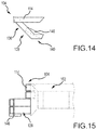
- FIG. 14 depicts a partial, top elevation view of one embodiment of the charging head of the present technology and further depicts one embodiment of a densification bar and one manner in which it can be coupled with a wing of the charging head.
- FIG. 15 depicts a side elevation view of the charging head and densification bar depicted in FIG. 14 .
- FIG. 16 depicts a partial side elevation view of one embodiment of the charging head of the present technology and further depicts another embodiment of a densification bar and a manner in which it can be coupled with the charging head.
- FIG. 17 depicts a partial, top elevation view of one embodiment of a charging head and charging frame, according to the present technology, and further depicts one embodiment of a slotted joint that couples the charging head and charging frame with one another.
- FIG. 18 depicts a partial, cutaway side elevation view of the charging head and charging frame depicted in FIG. 17 .
- FIG. 19 depicts a partial front elevation view of one embodiment of a charging head and charging frame, according to the present technology, and further depicts one embodiment of a charging frame deflection face that may be associated with the charging frame.
- FIG. 20 depicts a partial, cutaway side elevation view of the charging head and charging frame depicted in FIG. 19 .
- FIG. 21 depicts a front perspective view of one embodiment of an extrusion plate, according to the present technology, and further depicts one manner in which it may be associated with a rearward face of a charging head.
- FIG. 22 depicts a partial isometric view of the extrusion plate and charging head depicted in FIG. 21 .
- FIG. 23 depicts a side perspective view of one embodiment of an extrusion plate, according to the present technology, and further depicts one manner in which it may be associated with a rearward face of a charging head and extrude coal that is being conveyed into a coal charging system.
- FIG. 24A depicts a top plan view of another embodiment of extrusion plates, according to the present technology, and further depicts one manner in which they may be associated with wing members of a charging head.
- FIG. 24B depicts a side elevation view of the extrusion plates of FIG. 24A .
- FIG. 25A depicts a top plan view of still another embodiment of extrusion plates, according to the present technology, and further depicts one manner in which they may be associated with multiple sets of wing members that are disposed both forwardly and rearwardly of a charging head.
- FIG. 25B depicts a side elevation view of the extrusion plates of FIG. 25A .
- FIG. 26 depicts a front elevation view of one embodiment of a charging head, according to the present technology, and further depicts the differences in coal bed densities when an extrusion plate is used and not used in a coal bed charging operation.
- FIG. 27 depicts a plot of coal bed density over a length of a coal bed where the coal bed is charged without the use of an extrusion plate.
- FIG. 28 depicts a plot of coal bed density over a length of a coal bed where the coal bed is charged with the use of an extrusion plate.
- FIG. 29 depicts a top plan view of one embodiment of a charging head, according to the present technology, and further depicts another embodiment of an extrusion plate that may be associated with a rearward surface of the charging head.
- FIG. 30 depicts a top, plan view of a prior art false door assembly.
- FIG. 31 depicts a side elevation view of the false door assembly depicted in FIG. 30 .
- FIG. 32 depicts a side elevation view of one embodiment of a false door, according to the present technology, and further depicts one manner in which the false door may be coupled with an existing, angled false door assembly.
- FIG. 33 depicts a side elevation view of one manner in which a coal bed may be charged into a coke oven according to the present technology.
- FIG. 34A depicts a front perspective view of one embodiment of a false door assembly according to the present technology.
- FIG. 34B depicts a rear elevation view of one embodiment of a false door that may be used with the false door assembly depicted in FIG. 34A .
- FIG. 34C depicts a side elevation view of the false door assembly depicted in FIG. 34A and further depicts one manner in which a height of the false door may be selectively increased or decreased.
- FIG. 35A depicts a front perspective view of another embodiment of a false door assembly according to the present technology.
- FIG. 35B depicts a rear elevation view of one embodiment of a false door that may be used with the false door assembly depicted in FIG. 35A .
- FIG. 35C depicts a side elevation view of the false door assembly depicted in FIG. 35A and further depicts one manner in which a height of the false door may be selectively increased or decreased.
- FIG. 36 depicts two graphs comparatively, wherein the two graphs plot coke oven sole and crown temperatures over time for a twenty-four hour coking cycle and a forty-eight hour coking cycle.
- FIG. 37 depicts a plot of coal bed densities over a length of a coal bed for a thirty ton coal charge baseline coked over twenty-four hours, a thirty ton coal charge that has been at least partially extruded, according to the present technology, over twenty-four hours, and a forty-two ton coal charge baseline coked over forty-eight hours.
- FIG. 38 depicts a plot of coking time over coal bed density for coal beds of charge heights of twenty-four inches, thirty inches, thirty-six inches, forty-two inches, and forty-eight inches.
- FIG. 39 depicts a plot of coal processing rate over coal bed bulk density for coal beds of charge heights of twenty-four inches, thirty inches, thirty-six inches, forty-two inches, and forty-eight inches.
- FIG. 40 depicts a plot of coal processing rate over coal bed charge height for a variety of coal bed different bulk densities.
- the present technology is generally directed to methods of increasing a coal processing rate of coke ovens.
- the present technology is applied to methods of coking relatively small coal charges over relatively short time periods, resulting in an increase in coal processing rate.
- methods of the present technology are used with horizontal heat recovery coke ovens.
- embodiments of the present technology can be used with other coke ovens, such as horizontal, non-recovery ovens.
- coal is charged into the oven using a coal charging system that includes a charging head having opposing wings that extend outwardly and forwardly from the charging head, leaving an open pathway through which coal may be directed toward the side edges of the coal bed.
- an extrusion plate is positioned on a rearward face of the charging head and oriented to engage and compress coal as the coal is charged along a length of the coking oven.
- a false door is vertically oriented to maximize an amount of coal being charged into the oven.
- coal charging technology of the present matter will be used in combination with a pusher charger machine (“PCM”) having one or more other components common to PCMs, such as a door extractor, a pusher ram, a tripper conveyor, and the like.
- PCM pusher charger machine
- aspects of the present technology may be used separately from a PCM and may be used individually or with other equipment associated with a coking system. Accordingly, aspects of the present technology may simply be described as “a coal charging system” or components thereof. Components associated with coal charging systems, such as coal conveyers and the like that are well-known may not be described in detail, if at all, to avoid unnecessarily obscuring the description of the various embodiments of the technology.
- a coal charging system 100 having an elongated charging frame 102 and a charging head 104 .
- the charging frame 102 will be configured to have opposite sides 106 and 108 that extend between a distal end portion 110 and proximal end portion 112 .
- the proximal end portion 112 may be coupled with a PCM in a manner that permits selective extension and retraction of the charging frame 102 into, and from within, a coke oven interior during a coal charging operation.
- Other systems such as a height adjustment system that selectively adjusts the height of the charging frame 102 with respect to a coke oven floor and/or a coal bed, may also be associated with the coal charging system 100 .
- the charging head 104 is coupled with the distal end portion 110 of the elongated charging frame 102 .
- the charging head 104 is defined by a planar body 114 , having an upper edge portion 116 , lower edge portion 118 , opposite side portions 120 and 122 , a front face 124 , and a rearward face 126 .
- a substantial portion of the body 114 resides within a charging head plane. This is not to suggest that embodiments of the present technology will not provide charging head bodies having aspects that occupy one or more additional planes.
- the planar body is formed from a plurality of tubes, having square or rectangular cross-sectional shapes.
- the tubes are provided with a width of six inches to twelve inches. In at least one embodiment, the tubes have a width of eight inches, which demonstrated a significant resistance to warping during charging operations.
- various embodiments of the charging head 104 include a pair of opposing wings 128 and 130 that are shaped to have free end portions 132 and 134 .
- the free end portions 132 and 134 are positioned in a spaced-apart relationship, forwardly from the charging head plane.
- the free end portions 132 and 134 are spaced forwardly from the charging head plane a distance of six inches to 24 inches, depending on the size of the charging head 104 and the geometry of the opposing wings 128 and 130 . In this position, the opposing wings 128 and 130 define open spaces rearwardly from the opposing wings 128 and 130 , through the charging head plane.
- the present technology is adaptable as particular characteristics are presented from coking system to coking system.
- the opposing wings 128 and 130 include first faces 136 and 138 that extend outwardly from the charging head plane.
- the first faces 136 and 138 extend outwardly from the charging plane at a forty-five degree angle.
- the angle at which the first face deviates from the charging head plane may be increased or decreased according to the particular intended use of the coal charging system 100 .
- particular embodiments may employ an angle of ten degrees to sixty degrees, depending on the conditions anticipated during charging and leveling operations.
- the opposing wings 128 and 130 further include second faces 140 and 142 that extend outwardly from the first faces 136 and 138 toward the free distal end portions 132 and 134 .
- the second faces 140 and 142 of the opposing wings 128 and 130 reside within a wing plane that is parallel to the charging head plane.
- the second faces 140 and 142 are provided to be approximately ten inches in length. In other embodiments, however, the second faces 140 and 142 may have lengths ranging from zero to ten inches, depending on one or more design considerations, including the length selected for the first faces 136 and 138 and the angles at which the first faces 136 and 138 extend away from the charging plane. As depicted in FIGS.
- the opposing wings 128 and 130 are shaped to receive loose coal from the rearward face of the charging head 104 , while the coal charging system 100 is being withdrawn across the coal bed being charged, and funnel or otherwise direct loose coal toward the side edges of the coal bed.
- the coal charging system 100 may reduce the likelihood of voids at the sides of the coal bed, as shown in FIG. 2A .
- the wings 128 and 130 help to promote the level coal bed depicted in FIG. 2B . Testing has shown that use of the opposing wings 128 and 130 can increase the charge weight by one to two tons by filling these side voids.
- the shape of the wings 128 and 130 reduce drag back of the coal and spillage from the pusher side of the oven, which reduces waste and the expenditure of labor to retrieve the spilled coal.
- FIGS. 10A-10C another embodiment of a charging head 204 is depicted as having a planar body 214 , having an upper edge portion 216 , lower edge portion 218 , opposite side portions 220 and 222 , a front face 224 , and a rearward face 226 .
- the charging head 204 further includes a pair of opposing wings 228 and 230 that are shaped to have free end portions 232 and 234 that are positioned in a spaced-apart relationship, forwardly from the charging head plane.
- the free end portions 232 and 234 are spaced forwardly from the charging head plane a distance of six inches to 24 inches.
- the opposing wings 228 and 230 define open spaces rearwardly from the opposing wings 228 and 230 , through the charging head plane.
- the opposing wings 228 and 230 include first faces 236 and 238 that extend outwardly from the charging head plane at a forty-five degree angle.
- the angle at which the first faces 236 and 238 deviate from the charging head plane from ten degrees to sixty degrees, depending on the conditions anticipated during charging and leveling operations.
- the opposing wings 228 and 230 are shaped to receive loose coal from the rearward face of the charging head 204 , while the coal charging system is being withdrawn across the coal bed being charged, and funnel or otherwise direct loose coal toward the side edges of the coal bed.
- a further embodiment of a charging head 304 is depicted as having a planar body 314 , having an upper edge portion 316 , lower edge portion 318 , opposite side portions 320 and 322 , a front face 324 , and a rearward face 326 .
- the charging head 300 further includes a pair of curved opposing wings 328 and 330 that have free end portions 332 and 334 that are positioned in a spaced-apart relationship, forwardly from the charging head plane.
- the free end portions 332 and 334 are spaced forwardly from the charging head plane a distance of six inches to twenty-four inches.
- the curved opposing wings 328 and 330 define open spaces rearwardly from the curved opposing wings 328 and 330 , through the charging head plane.
- the curved opposing wings 328 and 330 include first faces 336 and 338 that extend outwardly from the charging head plane at a forty-five degree angle from a proximal end portion of the curved opposing wings 328 and 330 .
- the angle at which the first faces 336 and 338 deviate from the charging head plane from ten degrees to sixty degrees. This angle dynamically changes along lengths of the curved opposing wings 328 and 330 .
- the opposing wings 328 and 330 receive loose coal from the rearward face of the charging head 304 , while the coal charging system is being withdrawn across the coal bed being charged, and funnel or otherwise direct loose coal toward the side edges of the coal bed.
- an embodiment of a charging head 404 includes a planar body 414 , having an upper edge portion 416 , lower edge portion 418 , opposite side portions 420 and 422 , a front face 424 , and a rearward face 426 .
- the charging head 400 further includes a first pair of opposing wings 428 and 430 that have free end portions 432 and 434 that are positioned in a spaced-apart relationship, forwardly from the charging head plane.
- the opposing wings 428 and 430 include first faces 436 and 438 that extend outwardly from the charging head plane. In some embodiments, the first faces 436 and 438 extend outwardly from the charging head plane at a forty-five degree angle.
- the angle at which the first face deviates from the charging head plane may be increased or decreased according to the particular intended use of the coal charging system 400 .
- particular embodiments may employ an angle of ten degrees to sixty degrees, depending on the conditions anticipated during charging and leveling operations.
- the free end portions 432 and 434 are spaced forwardly from the charging head plane a distance of six inches to twenty-four inches.
- the opposing wings 428 and 430 define open spaces rearwardly from the curved opposing wings 428 and 430 , through the charging head plane.
- the opposing wings 428 and 430 further include second faces 440 and 442 that extend outwardly from the first faces 436 and 438 toward the free distal end portions 432 and 434 .
- the second faces 440 and 442 of the opposing wings 428 and 430 reside within a wing plane that is parallel to the charging head plane.
- the second faces 440 and 442 are provided to be approximately ten inches in length. In other embodiments, however, the second faces 440 and 442 may have lengths ranging from zero to ten inches, depending on one or more design considerations, including the length selected for the first faces 436 and 438 and the angles at which the first faces 436 and 438 extend away from the charging plane.
- the opposing wings 428 and 430 are shaped to receive loose coal from the rearward face of the charging head 404 , while the coal charging system 400 is being withdrawn across the coal bed being charged, and funnel or otherwise direct loose coal toward the side edges of the coal bed.
- opposing wings of various geometries may extend rearwardly from a charging head associated with a coal charging system according to the present technology.
- the charging head 400 further includes a second pair of opposing wings 444 and 446 that each include free end portions 448 and 450 that are positioned in a spaced-apart relationship, rearwardly from the charging head plane.
- the opposing wings 444 and 446 include first faces 452 and 454 that extend outwardly from the charging head plane. In some embodiments, the first faces 452 and 454 extend outwardly from the charging head plane at a forty-five degree angle.
- the angle at which the first faces 452 and 454 deviate from the charging head plane may be increased or decreased according to the particular intended use of the coal charging system 400 .
- particular embodiments may employ an angle of ten degrees to sixty degrees, depending on the conditions anticipated during charging and leveling operations.
- the free end portions 448 and 450 are spaced rearwardly from the charging head plane a distance of six inches to twenty-four inches.
- the opposing wings 444 and 446 define open spaces rearwardly from the opposing wings 444 and 446 , through the charging head plane.
- the opposing wings 444 and 446 further include second faces 456 and 458 that extend outwardly from the first faces 452 and 454 toward the free distal end portions 448 and 450 .
- the second faces 456 and 458 of the opposing wings 444 and 446 reside within a wing plane that is parallel to the charging head plane.
- the second faces 456 and 458 are provided to be approximately ten inches in length. In other embodiments, however, the second faces 456 and 458 may have lengths ranging from zero to ten inches, depending on one or more design considerations, including the length selected for the first faces 452 and 454 and the angles at which the first faces 452 and 454 extend away from the charging plane.
- the opposing wings 444 and 446 are shaped to receive loose coal from the front face 424 of the charging head 404 , while the coal charging system 400 is being extended along the coal bed being charged, and funnel or otherwise direct loose coal toward the side edges of the coal bed.
- the rearwardly faced opposing wings 444 and 446 are depicted as being positioned above the forwardly faced opposing wings 428 and 430 . However, it is contemplated that this particular arrangement may be reversed, in some embodiments, without departing from the scope of the present technology. Similarly, the rearwardly faced opposing wings 444 and 446 and forwardly faced opposing wings 428 and 430 are each depicted as angularly disposed wings having first and second sets of faces that are disposed at angles with respect to one another.
- either or both sets of opposing wings may be provided in different geometries, such as demonstrated by the straight, angularly disposed opposing wings 228 and 230 , or the curved wings 328 and 330 .
- Other combinations of known shapes, intermixed or in pairs, are contemplated.
- the charging heads of the present technology could be provided with one or more sets of opposing wings that only face rearwardly from the charging head, with no wings that face forwardly. In such instances, the rearwardly positioned opposing wings will distribute the coal to the side portions of the coal bed when the coal charging system is moving forward (charging).
- some embodiments of the present technology will include one or more angularly disposed particulate deflection surfaces 144 on top of the upper edge portion 116 of the charging head 104 .
- a pair of oppositely faced particulate deflection surfaces 144 combine to form a peaked structure, which disperses errant particulate material in front of and behind the charging head 104 .
- a single particulate deflection surface 144 may be provided with an orientation chosen to disperse the coal accordingly. It is further contemplated that the particulate deflection surfaces 144 may be provided in other, non-planar or non-angular configurations. In particular, the particulate deflection surfaces 144 may be flat, curvilinear, convex, concave, compound, or various combinations thereof. Some embodiments will merely dispose the particulate deflection surfaces 144 so that they are not horizontally disposed. In some embodiments, the particulate surfaces can be integrally formed with the upper edge portion 116 of the charging head 104 , which may further include a water cooling feature.
- Coal bed bulk density plays a significant role in determining coke quality and minimizing burn loss, particularly near the oven walls.
- the charging head 104 retracts against a top portion of the coal bed. In this manner, the charging head contributes to the top shape of the coal bed.
- particular aspects of the present technology cause portions of the charging head to increase the density of the coal bed.
- the opposing wings 128 and 130 may be provided with one or more elongated densification bars 146 that, in some embodiments, extend along a length of, and downwardly from, each of the opposing wings 128 and 130 . In some embodiments, such as depicted in FIGS.
- the densification bars 146 may extend downwardly from bottom surfaces of the opposing wings 128 and 130 . In other embodiments, the densification bars 146 may be operatively coupled with forward or rearward faces of either or both of the opposing wings 128 and 130 and/or the lower edge portion 118 of the charging head 104 . In particular embodiments, such as depicted in FIG. 13 , the elongated densification bar 146 has a long axis disposed at an angle with respect to the charging head plane. It is contemplated that the densification bar 146 may be formed from a roller that rotates about a generally horizontal axis, or a static structure of various shapes, such as a pipe or rod, formed from a high temperature material. The exterior shape of the elongated densification bar 146 may be planar or curvilinear. Moreover, the elongated densification bar may be curved along its length or angularly disposed.
- the charging heads and charging frames of various systems may not include a cooling system.
- the extreme temperatures of the ovens will cause portions of such charging heads and charging frames to expand slightly, and at different rates, with respect to one another.
- the rapid, uneven heating and expansion of the components may stress the coal charging system and warp or otherwise misalign the charging head with respect to the charging frame.
- embodiments of the present technology couple the charging head 104 to the sides 106 and 108 of the charging frame 102 using a plurality of slotted joints that allow relative movement between the charging head 104 and the elongated charging frame 102 .
- first frame plates 150 extend outwardly from inner faces of the sides 106 and 108 of the elongated frame 102 .
- the first frame plates 150 include one or more elongated mounting slots 152 that penetrate the first frame plates 150 .
- second frame plates 154 are also provided to extend outwardly from the inner faces of the sides 106 and 108 , beneath the first frame plates 150 .
- the second frame plates 154 of the elongated frame 102 also include one or more elongated mounting slots 152 that penetrate the second frame plates 154 .
- First head plates 156 extend outwardly from opposite sides of the rearward face 126 of the charging head 104 .
- the first head plates 156 include one or more mounting apertures 158 that penetrate the first head plates 156 .
- second head plates 160 are also provided to extend outwardly from the rearward face 126 of the charging head 104 , beneath the first head plates 156 .
- the second head plates 160 also include one or more mounting apertures 158 that penetrate the second head plates 158 .
- the charging head 104 is aligned with the charging frame 102 so that the first frame plates 150 align with first head pates 156 and the second frame plates 154 align with the second head plates 160 .
- Mechanical fasteners 161 pass through the elongated mounting slots 152 of the first frame plates 150 and second frame plates 152 and corresponding mounting apertures 160 .
- the mechanical fasteners 161 are placed in a fixed position with respect to the mounting apertures 160 but are allowed to move along lengths of the elongated mounting slots 152 as the charging head 104 move with respect to the charging frame 102 .
- the charging head 104 and the elongated charging frame 102 it is contemplated that more or fewer charging head plates and frame plates of various shapes and sizes could be employed to operatively couple the charging head 104 and the elongated charging frame 102 with one another.
- particular embodiments of the present technology provide the lower inner faces of each of the opposite sides 106 and 108 of the elongated charging frame 102 with charging frame deflection faces 162 , positioned to face at a slightly downward angle toward a middle portion of the charging frame 102 .
- the charging frame deflection faces 162 engage the loosely charged coal and direct the coal down and toward the sides of the coal bed being charged.
- the angle of the deflection faces 162 further compress the coal downwardly in a manner that helps to increase the density of the edge portions of the coal bed.
- forward end portions of each of the opposite sides 106 and 108 of the elongated charging frame 102 include charging frame deflection faces 163 that are also positioned rearwardly from the wings but are oriented to face forwardly and downwardly from the charging frame. In this manner, the deflection faces 163 may further help to increase the density of the coal bed and direct the coal outwardly toward the edge portions of the coal bed in an effort to more fully level the coal bed.
- FIG. 6 graphically depicts density measurements taken during mock oven testing. The top line shows the density of the coal bed surface. The lower two lines depict the density at twelve inches and twenty-four inches below the coal bed surface, respectively. From the testing data, one can conclude that bed density drops more significantly on the coke side of the oven.
- various embodiments of the present technology position an extrusion plate 166 operatively coupled with the rearward face 126 of the charging head 104 .
- the extrusion plate 166 includes a coal engagement face 168 that is oriented to face rearwardly and downwardly with respect to the charging head 104 . In this manner, loose coal being charged into the oven behind the charging head 104 will engage the coal engagement face 168 of the extrusion plate 166 . Due to the pressure of the coal being deposited behind the charging head 104 , the coal engagement face 168 compacts the coal downwardly, increasing the coal density of the coal bed beneath the extrusion plate 166 .
- the extrusion plate 166 extends substantially along a length of the charging head 104 in order to maximize density across a significant width of the coal bed.
- the extrusion plate 166 further includes an upper deflection face 170 that is oriented to face rearwardly and upwardly with respect to the charging head 104 .
- the coal engagement face 168 and the upper deflection face 170 are coupled with one another to define a peak shape, having a peak ridge that faces rearwardly away from the charging head 104 . Accordingly, any coal that falls atop the upper deflection face 170 will be directed off the extrusion plate 166 to join the incoming coal before it is extruded.
- coal is shuffled to the front end portion of the coal charging system 100 , behind the charging head 104 .
- Coal piles up in the opening between the conveyor and the charging head 104 and conveyor chain pressure starts to build up gradually until reaching approximately 2500 to 2800 psi.
- the coal is fed into the system behind the charging head 104 and the charging head 104 is retracted, rearwardly through the oven.
- the extrusion plate 166 compacts the coal and extrudes it into the coal bed.
- embodiments of the present technology may associate extrusion plates with one or more wings that extend from the charging head.
- the extrusion plates 266 are provided with coal engagement faces 268 and upper deflection faces 270 that are coupled with one another to define a peak shape, having a peak ridge that faces rearwardly away from the opposing wings 128 and 130 .
- the coal engagement faces 268 are positioned to compact the coal downwardly as the coal charging system is retracted through the oven, increasing the coal density of the coal bed beneath the extrusion plates 266 .
- 25A and 25B depict a charging head similar to that depicted in FIGS. 12A-12C except that extrusion plates 466 , having coal engagement faces 468 and upper deflection faces 470 , are positioned to extend rearwardly from the opposing wings 428 and 430 .
- the extrusion plates 466 function similarly to the extrusion plates 266 .
- Additional extrusion plates 466 may be positioned to extend forwardly from the opposing wings 444 and 446 , which are positioned behind the charging head 400 .
- Such extrusion plates compact the coal downwardly as the coal charging system is advanced through the oven, further increasing the coal density of the coal bed beneath the extrusion plates 466 .
- FIG. 26 depicts the effect on the density of a coal charge with the benefit of the extrusion plate 166 (left side of the coal bed) and without the benefit of the extrusion plate 166 (right side of the coal bed).
- use of the extrusion plate 166 provides area “D” of increased coal bed bulk density and an area of lesser coal bed bulk density “d” where the extrusion plate is not present.
- the extrusion plate 166 not only demonstrates an improvement in the surface density, but also improves the overall internal bed bulk density.
- FIGS. 27 and 28 below show the improvement of bed density with the use of the extrusion plate 166 ( FIG. 28 ) and without the use of the extrusion plate 166 ( FIG. 27 ).
- the data demonstrates a significant impact on both surface density and twenty-four inches below the surface of the coal bed.
- an extrusion plate 166 having a ten inch peak (distance from back of the charging head 104 to the peak ridge of the extrusion plate 166 , where the coal engagement face 168 and the upper deflection face 170 meet).
- coal density was increased but not to the levels resulting from the use of the ten inch peak extrusion plate 166 .
- the data reveals that the use of the ten inch peak extrusion plate increased the density of the coal bed, which allowed for an increase in charge weight of approximately two and a half tons.
- smaller extrusion plates of five to ten inches in peak height, for example, or larger extrusion plates, of ten to twenty inches in peak height, for example, could be used.
- extrusion plate 166 that is shaped to include opposing side deflection faces 172 that are oriented to face rearwardly and laterally with respect to the charging head 104 .
- extrusion plate 166 helps to promote the level coal bed, depicted in FIG. 2B , as well as an increase in coal bed density across the width of the coal bed.
- coal charging systems When charging systems extend inside the ovens during charging operations, the coal charging systems, typically weighing approximately 80,000 pounds, deflect downwardly at their free, distal ends. This deflection shortens the coal charge capacity.
- FIG. 5 shows that the bed height drop, due to coal charging system deflection, is from five inches to eight inches between the pusher side to the coke side, depending upon the charge weight. In general, coal charging system deflection can cause a coal volume loss of approximately 1 to 2 tons.
- coal piles up in the opening between the conveyor and the charging head 104 and conveyor chain pressure starts to build up.
- Traditional coal charging systems operate at a chain pressure of approximately 2300 psi.
- the coal charging system of the present technology can be operated at a chain pressure of approximately 2500 to 2800 psi.
- This increase in chain pressure increases the rigidity of the coal charging system 100 along a length of its charging frame 102 .
- Testing indicates that operating the coal charging system 100 at a chain pressure of approximately 2700 psi reduces deflection of the coal charging system deflection by approximately two inches, which equates to a higher charge weight and increased production.
- Testing has further shown that operating the coal charging system 100 at a higher chain pressure of approximately 3000 to 3300 psi can produce a more effective charge and further realize greater benefit from the use of one or more extrusion plates 166 , as described above.
- various embodiments of the coal charging system 100 include a false door assembly 500 , having an elongated false door frame 502 and a false door 504 , which is coupled to a distal end portion 506 of the false door frame 502 .
- the false door frame 502 further includes a proximal end portion 508 , and opposite sides 510 and 512 that extend between the proximal end portion 508 and the distal end portion 506 .
- the proximal end portion 508 may be coupled with a PCM in a manner that permits selective extension and retraction of the false door frame 502 into and from within a coke oven interior during a coal charging operation.
- the false door frame 502 is coupled with the PCM adjacent to and, in many instances, beneath the charging frame 102 .
- the false door 504 is generally planar, having an upper end portion 514 , a lower end portion 516 , opposite side portions 518 and 520 , a front face 522 , and a rearward face 524 .
- the false door 504 is placed just inside the coke oven during a coal charging operation. In this manner, the false door 504 substantially prevents loose coal from unintentionally exiting the pusher side of the coke oven until the coal is fully charged and the coke oven can be closed.
- the false door 504 includes an extension plate 526 , having an upper end portion 528 , a lower end portion 530 , opposite side portions 530 and 534 , a front face 536 , and a rearward face 538 .
- the upper end portion 528 of extension plate 526 is removably coupled to the lower end portion 516 of the false door 504 so that the lower end portion 530 of the extension plate 526 extends lower than the lower end portion 516 of the false door 504 . In this manner a height of the front face 522 of the false door 504 may be selectively increased to accommodate the charging of a coal bed having a greater height.
- the extension plate 526 is typically coupled with the false door 504 using a plurality of mechanical fasteners 540 that form a quick connect/disconnect system.
- a plurality of separate extension plates 526 may be associated with a false door assembly 500 .
- a longer extension plate 526 may be used for coal charges of forty-eight tons
- a shorter extension plate 526 may be used for a coal charge of thirty-six tons
- no extension plate 526 might be used for a coal charge of twenty-eight tons.
- removing and replacing the extension plates 526 is labor intensive and time consuming, due to the weight of the extension plate and the fact that it is manually removed and replaced. This procedure can interrupt coke production at a facility by an hour or more.
- an existing false door 504 that resides within a body plane, which is disposed at an angle away from vertical, may be adapted to have a vertical false door.
- a false door extension 542 having an upper end portion 544 , a lower end portion 546 , a front face 548 , and a rearward face 550 , may be operatively coupled with the false door 504 .
- the false door extension 542 is shaped and oriented to define a replacement front face of the false door 504 . It is contemplated that the false door extension 542 can be coupled with the false door 504 using mechanical fasteners, welding, or the like.
- the front face 548 is positioned to reside within a false door plane that is substantially vertical. In some embodiments, the front face 548 is shaped to closely mirror a contour of a refractory surface 552 of a pusher side oven door 554 .
- the vertical orientation of the front face 548 allows the false door extension 542 to be placed just inside the coke oven during a coal charging operation.
- an end portion of the coal bed 556 is positioned closely adjacent the refractory surface 552 of the pusher side oven door 554 .
- the six to twelve inch gap left between the coal bed and the refractory surface 552 can be eliminated or, at the very least, minimized significantly.
- the vertically disposed front face 548 of the false door extension 542 maximizes the use of the full oven capacity to charge more coal into the oven, as opposed to the sloped bed shape created by the prior art designs, which increases the production rate for the oven.
- each oven can charge an additional half ton to a full ton of coal, which can significantly improve the coal processing rate for an entire oven battery.
- a forty-nine ton charge may be placed into an oven typically operated with forty-eight ton charges.
- the forty-nine ton charge will not increase the forty-eight hour coke cycle. If the twelve inch void is filled using the aforementioned methodology but only forty-eight tons of coal are charged into the oven, the bed will be reduced from an expected forty-eight inches high to forty-seven inches high. Coking the forty-seven inch high coal charge for forty-eight hours buys one additional hour of soak time for the coking process, which could improve coke quality (CSR or stability).
- the false door frame 502 may be fitted with a vertical false door 558 , in place of the false door 504 .
- the vertical false door 558 has an upper end portion 560 , a lower end portion 562 , opposite side portions 564 and 566 , a front face 568 , and a rearward face 570 .
- the front face 568 is positioned to reside within a false door plane that is substantially vertical.
- the front face 568 is shaped to closely mirror a contour of a refractory surface 552 of a pusher side oven door 554 . In this manner, the vertical false door may be used much in the same manner as that described above with regard to the false door assembly that employs a false door extension 542 .
- an oven may be first charged with a forty-eight ton, forty-eight inch high, coal bed. Thereafter, the oven may be charged with a twenty-eight ton, twenty-eight inch high, coal bed.
- the different bed heights require the use of false doors of correspondingly different heights.
- various embodiments of the present technology provide a lower extension plate 572 coupled with the front face 568 of the vertical false door 558 .
- the lower extension plate 572 is selectively, vertically moveable with respect to the vertical false door 558 between retracted and extended positions.
- At least one extended position disposes a lower edge portion 574 of the lower extension plate 572 below the lower edge portion 562 of the vertical false door 558 such that an effective height of the vertical false door 558 is increased.
- relative movement between the lower extension plate 572 and the vertical false door 558 is effected by disposing one or more extension plate brackets 576 , which extend rearwardly from the lower extension plate 572 , through one or more vertically arranged slots 578 that penetrate the vertical false door 558 .
- One of various arm assemblies 580 and power cylinders 582 may be coupled to the extension plate brackets 576 to selectively move the lower extension plate 572 between its retracted and extended positions.
- the effective height of the vertical false door 558 may be automatically customized to any height, ranging from an initial height of the vertical false door 558 to a height with the lower extension plate 572 at a full extension position.
- the lower extension plate 558 and its associated components may be operatively coupled with the false door 504 , such as depicted in FIGS. 35A-35C .
- the lower extension plate 558 and its associated components may be operatively coupled with the extension plate 526 .
- the end portion of the coal bed 556 may be slightly compacted to reduce the likelihood that the end portion of the coal charge will spill from the oven before the pusher side oven door 554 can be closed.
- one or more vibration devices may be associated with the false door 504 , extension plate 526 , or vertical false door 558 , in order to vibrate the false door 504 , extension plate 526 , or vertical false door 558 , and compact the end portion of the coal bed 556 .
- the elongated false door frame 502 may be reciprocally and repeatedly moved into contact with the end portion of the coal bed 204 with sufficient force to compact the end portion of the coal bed 556 .
- a water spray may also be used, alone or in conjunction with the vibratory or impact compaction methods, to moisten the end portion of the coal bed 556 and, at least temporarily, maintain a shape of the end portion of the coal bed 556 so that portions of the coal bed 556 do not spill from the coke oven.
- coal processing rates can be increased by twenty percent or more over a forty-eight hour period.
- a coal charging system 100 having an elongated charging frame 102 and a charging head 104 coupled with the distal end portion of the elongated charging frame 102 , is positioned at least partially within a coke oven.
- the coke oven is at least partially defined by a maximum designed coal charge capacity (volume per charge).
- the maximum designed coal charge capacity is defined as the maximum volume of coal that can be charged into a coke oven according to the width and length of a coke oven multiplied by a maximum bed height, which is typically defined by a height of downcomer openings, formed in the coke oven's opposing side walls, above the coke oven floor.
- the volume will further vary according to the density of the coal charge throughout the coal bed.
- the maximum coal charge of the coke oven is associated with a maximum coking time (the designed coking time associated with the designed coal volume per charge).
- the maximum coking time is defined as the longest amount of time in which the coal bed may be fully coked.
- the maximum coking time is, in various embodiments, constrained by the amount of volatile matter within the coal bed that may be converted into heat over the duration of the coking process. Further constraints on the maximum coking time include the maximum and minimum coking temperatures of the coking oven being used, as well as the density of the coal bed and the quality of coal being coked.
- the coal is charged into the coke oven with the coal charging system 100 in a manner that defines a first operational coal charge that is less than the maximum coal charge capacity.
- the first operational coal charge is coked in the coke oven until it is converted into a first coke bed over a first coking time that is less than the maximum coking time.
- the first coke bed is then pushed from the coke oven.
- More coal may then be charged into the coke oven by the coal charging system to define a second operational coal charge that is less than the maximum coal charge capacity.
- the second operational coal charge is coked in the coke oven until it is converted into a second coke bed over a second coking time that is less than the maximum coking time.
- the second coke bed may then be pushed from the coke oven.
- a sum of the first operational coal charge and the second operational coal charge exceeds a weight of the maximum coal charge capacity.
- a sum of the first coking time and the second coking time are less than the maximum coking time.
- the first operational coal charge and second operational coal charge have individual weights that are at least more than half of the weight of the maximum coal charge capacity.
- the first operational coal charge and second operational coal charge each have a weight of between 24 and 30 tons.
- the duration of each of the first coking time and second coking time approximates half of the maximum coking time or less.
- the sum of the first coking time and the second coking time is 48 hours or less.
- the coke oven is charged with approximately twenty-eight and one half tons of coal.
- the charge is fully coked over a twenty-four hour period. Once complete, the coke is pushed from the coke oven and a second coal charge of twenty-eight and one half tons is charged into the coke oven. Twenty-four hours later, the charge is fully coked and pushed from the oven. Accordingly, one oven has coked fifty-seven tons of coal in forty-eight hours, providing a coal processing rate of 1.19 ton/hour for a twenty-one percent increase.
- oven control burn efficiency and thermal management to maintain oven thermal energy
- coal charging techniques that balance oven heat from one end of the bed to the other.
- a comparison of the oven burning profiles for twenty-four hour and forty-eight hour coking cycles reveals differences in the characteristics of the two burn profiles.
- One significant difference between the two burn profiles is the crossover time between the crown and sole flue temperatures. Specifically, the crossover time is longer in a twenty-four hour coking cycle, which tries to reserve more heat in the oven, both for the current coking cycle and to maintain high oven heat for the next coking cycle. Reducing the charge from forty-seven tons (typically forty-seven inches in height) to twenty-eight and one half tons (twenty-eight and one half inches) significantly decreases oven volume occupied by the coal bed. Therefore, an oven that is charged with a lighter bed of coal will have less volatile material to burn over the coking cycle. Accordingly, maintaining proper heat levels in the oven is an issue for twenty-four hour coking cycles.
- the oven startup temperature is generally higher for twenty-four hour coking cycles (greater than 2,100° F.) than forty-eight hour coking cycles (less than 2,000° F.).
- the heat may be maintained over the coking cycle by controlling the release of the volatile material from the coal bed.
- uptake dampers are precisely controlled to adjust oven draft. In this manner, the oxygen intake of the oven, and combustion of the volatile material, may be managed to ensure that the supply of volatile material is not exhausted too early in the coking cycle.
- the twenty-four hour cycle maintains a higher average cycle temperature than that for the forty-eight hour cycle.
- the power cylinder 582 is actuated to engage the arm assemblies 580 and retract the lower extension plate 572 with respect to the front face 568 of the vertical false door 558 .
- the lower extension plate 572 is retracted until the vertical false door 558 is properly sized to be disposed between the coal charging system 100 and the floor of the coke oven, adjacent the pusher side oven door 554 .
- the coke quality was improved by charging the coal bed of thirty tons or less using a coal charging system 100 having an extrusion plate 166 .
- loose coal is conveyed into the coal charging system 100 behind the charging head 104 and engages the coal engagement face 168 .
- the coal engagement face 168 compacts the coal downwardly, into the coal bed.
- the pressure of the coal being deposited behind the charging head 104 increases the density of the coal bed beneath the extrusion plate 166 .
- FIG. 37 depicts at least some of the density increasing benefits attributable to the extrusion plate 166 .
- the extruded coal bed In tests involving a thirty ton non-extruded coal bed, a thirty ton extruded coal bed, and a forty-two ton non-extruded coal bed, the extruded coal bed exhibited a bed density that was consistently higher than the non-extruded coal bed of the same weight. In fact, the extruded coal bed weighing thirty tons had a density that was similar to better than the forty-two ton coal bed. Extruding the smaller coal beds generally lowers the bed height by approximately one inch, while maintaining the same charge weight. Accordingly, the bed receives the added benefit of an additional hour for soak time. Further testing of the sample indicated that the higher coal bulk density improved the soak time of the bed, as well as the resulting coke stability, CSR, and coke size.
- coking time is plotted against coal bed density for coal beds of five different heights.
- the data demonstrates the increase in production rate through the use of the present technology.
- a first coal bed having a height of 37.7 inches, a weight of 56.0 tons, and a bed density of 73.5 lbs./cu. ft. was fully coked in forty-eight hours. This provides a coking rate of 1.167 tons per hour.
- a second coal bed having a height of 24.0 inches, a weight of nearly 28.7 tons, and a bed density of 59.2 lbs./cu. ft. was fully coked in twenty-four hours. This provides a coking rate of 1.196 tons per hour.
- coal processing rate is plotted against bulk density for coal beds of charge heights of thirty inches, thirty-six inches, forty-two inches, and forty-eight inches.
- FIG. 40 coal processing rate is plotted against charge height for a variety of coal bed different bulk densities.
- a method of increasing a coal processing rate of a coke oven comprising:
- first operational coal charge and second operational coal charge each have a weight of between 24 and 30 tons.
- the extrusion plate is shaped to include opposing side deflection faces that are oriented to face rearwardly and laterally with respect to the charging head and portions of the coal are extruded by the opposing side deflection faces.
- a method of increasing a coal processing rate of a coke oven comprising:
- a method of increasing a coal processing rate of a horizontal heat recovery coke oven comprising:
- a stated range of 1 to 10 should be considered to include and provide support for claims that recite any and all subranges or individual values that are between and/or inclusive of the minimum value of 1 and the maximum value of 10; that is, all subranges beginning with a minimum value of 1 or more and ending with a maximum value of 10 or less (e.g., 5.5 to 10, 2.34 to 3.56, and so forth) or any values from 1 to 10 (e.g., 3, 5.8, 9.9994, and so forth).
Abstract
Description
-
- positioning a coal charging system, having an elongated charging frame and a charging head operatively coupled with the distal end portion of the elongated charging frame, at least partially within a coke oven having a maximum coal charge capacity and a maximum coking time associated with the maximum coal charge;
- charging coal into the coke oven with the coal charging system in a manner that defines a first operational coal charge that is less than the maximum coal charge capacity;
- coking the first operational coal charge in the coke oven until it is converted into a first coke bed but over a first coking time that is less than the maximum coking time;
- pushing the first coke bed from the coke oven;
- charging coal into the coke oven with the coal charging system in a manner that defines a second operational coal charge that is less than the maximum coal charge capacity;
- coking the second operational coal charge in the coke oven until it is converted into a second coke bed but over a second coking time that is less than the maximum coking time; and
- pushing the second coke bed from the coke oven;
- a sum of the first operational coal charge and the second operational coal charge exceeds a weight of the maximum coal charge capacity;
- a sum of the first coking time and the second coking time being less than the maximum coking time.
-
- extruding at least portions of the coal being charged into the coke oven by engaging the portions of the coal with an extrusion plate operatively coupled with a rearward face of the charging head, such that the portions of coal are compressed beneath a coal engagement face that is oriented to face rearwardly and downwardly with respect to the charging head.
-
- gradually withdrawing the coal charging system so that a portion of the coal flows through a pair of opposing wing openings that penetrate lower side portions of the charging head and engage a pair of opposing wings having free end portions positioned in a spaced-apart relationship, forwardly from a front face of the charging head, such that the portion of the coal is directed toward side portions of a coal bed being formed by the coal charging system.
-
- compressing portions of the coal bed beneath the opposing wings by engaging elongated densification bars, which extend along a length of, and downwardly from, each of the opposing wings, with the portions of the coal bed as the coal charging system is withdrawn.
-
- supporting a rearward portion of the coal bed with a false door system having a generally planar false door that is operatively coupled with a distal end portion of an elongated false door frame.
-
- vertically moving a lower extension plate that is operatively coupled with the front face of the false door, to a retracted position that disposes a lower edge portion of the lower extension plate no lower than a lower edge portion of the false door and decreases an effective height of the false door, prior to supporting the rearward portion of the coal bed.
-
- charging a bed of coal into a coke oven in a manner that defines an operational coal charge; the coke oven having a designed coal processing rate that is defined by a designed coal charge and a designed coking time associated with the designed coal charge; the operational coal charge being less than the designed coal charge;
- coking the operational coal charge in the coke oven over an operational coking time to define an operational coal processing rate; the operational coking time being less than the designed coking time; wherein the operational coal processing rate is greater than the designed coal processing rate.
-
- charging coal into a coke oven with a coal charging system in a manner that defines a first operational coal charge that weighs between 24 and 30 tons;
- coking the first operational coal charge in the coke oven until it is converted into a first coke bed but over a first coking time that is no more than 24 hours;
- pushing the first coke bed from the coke oven;
- charging coal into the coke oven with the coal charging system in a manner that defines a second operational coal charge that weighs between 24 and 30 tons;
- coking the second operational coal charge in the coke oven until it is converted into a second coke bed but over a second coking time that is no more than 24 hours; and
- pushing the second coke bed from the coke oven.
-
- extruding at least portions of the coal being charged into the coke oven with the coal charging system by engaging the portions of the coal with an extrusion plate operatively coupled with a rearward face of a charging head associated with the coal charging system, such that the portions of coal are compressed beneath the extrusion plate.
-
- charging coal into the coke oven in a manner that defines a first operational coal charge that is less than the designed coal volume per charge;
- coking the first operational coal charge in the coke oven until it is converted into a first coke bed but over a first coking time that is less than the designed coking time;
- pushing the first coke bed from the coke oven;
- charging coal into the coke oven in a manner that defines a second operational coal charge that is less than the designed coal volume per charge;
- coking the second operational coal charge in the coke oven until it is converted into a second coke bed but over a second coking time that is less than the designed coking time; and
- pushing the second coke bed from the coke oven;
- a sum of the first operational coal charge and the second operational coal charge exceeding a weight of the designed coal volume per charge;
- a sum of the first coking time and the second coking time being less than the designed coking time.
Claims (19)
Priority Applications (1)
| Application Number | Priority Date | Filing Date | Title |
|---|---|---|---|
| US16/251,352 US11053444B2 (en) | 2014-08-28 | 2019-01-18 | Method and system for optimizing coke plant operation and output |
Applications Claiming Priority (3)
| Application Number | Priority Date | Filing Date | Title |
|---|---|---|---|
| US201462043359P | 2014-08-28 | 2014-08-28 | |
| US14/839,493 US10233392B2 (en) | 2014-08-28 | 2015-08-28 | Method for optimizing coke plant operation and output |
| US16/251,352 US11053444B2 (en) | 2014-08-28 | 2019-01-18 | Method and system for optimizing coke plant operation and output |
Related Parent Applications (1)
| Application Number | Title | Priority Date | Filing Date |
|---|---|---|---|
| US14/839,493 Continuation US10233392B2 (en) | 2014-08-28 | 2015-08-28 | Method for optimizing coke plant operation and output |
Publications (2)
| Publication Number | Publication Date |
|---|---|
| US20190352568A1 US20190352568A1 (en) | 2019-11-21 |
| US11053444B2 true US11053444B2 (en) | 2021-07-06 |
Family
ID=55400694
Family Applications (8)
| Application Number | Title | Priority Date | Filing Date |
|---|---|---|---|
| US14/839,551 Active 2037-05-13 US10308876B2 (en) | 2014-08-28 | 2015-08-28 | Burn profiles for coke operations |
| US14/839,588 Active US9708542B2 (en) | 2014-08-28 | 2015-08-28 | Method and system for optimizing coke plant operation and output |
| US14/839,384 Active US9580656B2 (en) | 2014-08-28 | 2015-08-28 | Coke oven charging system |
| US14/839,493 Active US10233392B2 (en) | 2014-08-28 | 2015-08-28 | Method for optimizing coke plant operation and output |
| US15/443,246 Active US9976089B2 (en) | 2014-08-28 | 2017-02-27 | Coke oven charging system |
| US16/251,352 Active US11053444B2 (en) | 2014-08-28 | 2019-01-18 | Method and system for optimizing coke plant operation and output |
| US16/428,014 Active US10920148B2 (en) | 2014-08-28 | 2019-05-31 | Burn profiles for coke operations |
| US17/155,719 Active US11441078B2 (en) | 2014-08-28 | 2021-01-22 | Burn profiles for coke operations |
Family Applications Before (5)
| Application Number | Title | Priority Date | Filing Date |
|---|---|---|---|
| US14/839,551 Active 2037-05-13 US10308876B2 (en) | 2014-08-28 | 2015-08-28 | Burn profiles for coke operations |
| US14/839,588 Active US9708542B2 (en) | 2014-08-28 | 2015-08-28 | Method and system for optimizing coke plant operation and output |
| US14/839,384 Active US9580656B2 (en) | 2014-08-28 | 2015-08-28 | Coke oven charging system |
| US14/839,493 Active US10233392B2 (en) | 2014-08-28 | 2015-08-28 | Method for optimizing coke plant operation and output |
| US15/443,246 Active US9976089B2 (en) | 2014-08-28 | 2017-02-27 | Coke oven charging system |
Family Applications After (2)
| Application Number | Title | Priority Date | Filing Date |
|---|---|---|---|
| US16/428,014 Active US10920148B2 (en) | 2014-08-28 | 2019-05-31 | Burn profiles for coke operations |
| US17/155,719 Active US11441078B2 (en) | 2014-08-28 | 2021-01-22 | Burn profiles for coke operations |
Country Status (14)
| Country | Link |
|---|---|
| US (8) | US10308876B2 (en) |
| EP (4) | EP3186336B1 (en) |
| JP (7) | JP6208919B1 (en) |
| KR (4) | KR101845209B1 (en) |
| CN (4) | CN107109237A (en) |
| AU (6) | AU2015308678B2 (en) |
| BR (4) | BR112017004037B1 (en) |
| CA (5) | CA2959618C (en) |
| CO (4) | CO2017001976A2 (en) |
| PL (3) | PL3186340T3 (en) |
| RU (4) | RU2697555C2 (en) |
| UA (4) | UA124610C2 (en) |
| WO (4) | WO2016033511A1 (en) |
| ZA (1) | ZA201701787B (en) |
Cited By (16)
| Publication number | Priority date | Publication date | Assignee | Title |
|---|---|---|---|---|
| US11505747B2 (en) | 2018-12-28 | 2022-11-22 | Suncoke Technology And Development Llc | Coke plant tunnel repair and anchor distribution |
| US11643602B2 (en) | 2018-12-28 | 2023-05-09 | Suncoke Technology And Development Llc | Decarbonization of coke ovens, and associated systems and methods |
| US11680208B2 (en) | 2018-12-28 | 2023-06-20 | Suncoke Technology And Development Llc | Spring-loaded heat recovery oven system and method |
| US11692138B2 (en) | 2012-08-17 | 2023-07-04 | Suncoke Technology And Development Llc | Automatic draft control system for coke plants |
| US11746296B2 (en) | 2013-03-15 | 2023-09-05 | Suncoke Technology And Development Llc | Methods and systems for improved quench tower design |
| US11767482B2 (en) | 2020-05-03 | 2023-09-26 | Suncoke Technology And Development Llc | High-quality coke products |
| US11788012B2 (en) | 2015-01-02 | 2023-10-17 | Suncoke Technology And Development Llc | Integrated coke plant automation and optimization using advanced control and optimization techniques |
| US11795400B2 (en) | 2014-09-15 | 2023-10-24 | Suncoke Technology And Development Llc | Coke ovens having monolith component construction |
| US11807812B2 (en) | 2012-12-28 | 2023-11-07 | Suncoke Technology And Development Llc | Methods and systems for improved coke quenching |
| US11819802B2 (en) | 2018-12-31 | 2023-11-21 | Suncoke Technology And Development Llc | Methods and systems for providing corrosion resistant surfaces in contaminant treatment systems |
| US11845898B2 (en) | 2017-05-23 | 2023-12-19 | Suncoke Technology And Development Llc | System and method for repairing a coke oven |
| US11845037B2 (en) | 2012-12-28 | 2023-12-19 | Suncoke Technology And Development Llc | Systems and methods for removing mercury from emissions |
| US11845897B2 (en) | 2018-12-28 | 2023-12-19 | Suncoke Technology And Development Llc | Heat recovery oven foundation |
| US11851724B2 (en) | 2021-11-04 | 2023-12-26 | Suncoke Technology And Development Llc. | Foundry coke products, and associated systems, devices, and methods |
| US11939526B2 (en) | 2012-12-28 | 2024-03-26 | Suncoke Technology And Development Llc | Vent stack lids and associated systems and methods |
| US11946108B2 (en) | 2021-11-04 | 2024-04-02 | Suncoke Technology And Development Llc | Foundry coke products and associated processing methods via cupolas |
Families Citing this family (20)
| Publication number | Priority date | Publication date | Assignee | Title |
|---|---|---|---|---|
| US9243186B2 (en) | 2012-08-17 | 2016-01-26 | Suncoke Technology And Development Llc. | Coke plant including exhaust gas sharing |
| US9238778B2 (en) | 2012-12-28 | 2016-01-19 | Suncoke Technology And Development Llc. | Systems and methods for improving quenched coke recovery |
| US10760002B2 (en) | 2012-12-28 | 2020-09-01 | Suncoke Technology And Development Llc | Systems and methods for maintaining a hot car in a coke plant |
| US10047295B2 (en) | 2012-12-28 | 2018-08-14 | Suncoke Technology And Development Llc | Non-perpendicular connections between coke oven uptakes and a hot common tunnel, and associated systems and methods |
| WO2015103414A1 (en) | 2013-12-31 | 2015-07-09 | Suncoke Technology And Development Llc | Methods for decarbonizing coking ovens, and associated systems and devices |
| BR112016030880B1 (en) | 2014-06-30 | 2021-05-04 | Suncoke Technology And Development Llc | horizontal heat recovery coke oven chamber |
| CA2959618C (en) | 2014-08-28 | 2019-10-29 | Suncoke Technology And Development Llc | Method and system for optimizing coke plant operation and output |
| US10968395B2 (en) | 2014-12-31 | 2021-04-06 | Suncoke Technology And Development Llc | Multi-modal beds of coking material |
| US11060032B2 (en) | 2015-01-02 | 2021-07-13 | Suncoke Technology And Development Llc | Integrated coke plant automation and optimization using advanced control and optimization techniques |
| CA3203921A1 (en) | 2015-12-28 | 2017-07-06 | Suncoke Technology And Development Llc | Method and system for dynamically charging a coke oven |
| CN109313443A (en) | 2016-06-03 | 2019-02-05 | 太阳焦炭科技和发展有限责任公司 | For automatically generating the method and system of remedial measure in industrial plants |
| KR101927772B1 (en) * | 2017-08-29 | 2018-12-11 | 주식회사 포스코 | Planarizing apparatus and method thereof |
| TWI681048B (en) * | 2017-09-15 | 2020-01-01 | 德商蒂森克虜伯工業解決方案股份有限公司 | Coke oven device having a circular flow path with an encircling flow around it for the production of coke, and method for operating the coke oven device, and control installation, and use thereof |
| US11760937B2 (en) | 2018-12-28 | 2023-09-19 | Suncoke Technology And Development Llc | Oven uptakes |
| BR112021012718B1 (en) | 2018-12-28 | 2022-05-10 | Suncoke Technology And Development Llc | Particulate detection system for use in an industrial facility and method for detecting particulate matter in an industrial gas facility |
| BR112021012412A2 (en) | 2018-12-31 | 2021-09-08 | Suncoke Technology And Development Llc | IMPROVED SYSTEMS AND METHODS TO USE COMBUSTION GAS |
| DE102019206628B4 (en) * | 2019-05-08 | 2024-04-18 | Thyssenkrupp Ag | Coke oven device for producing coke and method for operating the coke oven device and use |
| WO2021134071A1 (en) * | 2019-12-26 | 2021-07-01 | Suncoke Technology And Development Llc | Oven health optimization systems and methods |
| CN112746169B (en) * | 2021-02-04 | 2022-08-19 | 大冶有色金属有限责任公司 | Method for quickly melting coke by spray gun of Ausmelt smelting furnace |
| CN113322085A (en) * | 2021-07-02 | 2021-08-31 | 攀钢集团攀枝花钢钒有限公司 | Coal cake production method for tamping coking |
Citations (519)
| Publication number | Priority date | Publication date | Assignee | Title |
|---|---|---|---|---|
| US425797A (en) | 1890-04-15 | Charles w | ||
| US469868A (en) | 1892-03-01 | Apparatus for quenching coke | ||
| US845719A (en) | 1899-08-01 | 1907-02-26 | United Coke & Gas Company | Apparatus for charging coke-ovens. |
| DE201729C (en) | 1956-08-25 | 1908-09-19 | Franz Meguin & Co Ag | DEVICE FOR SCRAPING GRAPHITE APPROACHES AND THE DIGITAL VOCES OF KOKS CHAMBERS |
| DE212176C (en) | 1908-04-10 | 1909-07-26 | ||
| US976580A (en) | 1909-07-08 | 1910-11-22 | Stettiner Chamotte Fabrik Actien Ges | Apparatus for quenching incandescent materials. |
| US1140798A (en) | 1915-01-02 | 1915-05-25 | Riterconley Mfg Company | Coal-gas-generating apparatus. |
| US1424777A (en) | 1915-08-21 | 1922-08-08 | Schondeling Wilhelm | Process of and device for quenching coke in narrow containers |
| US1430027A (en) | 1920-05-01 | 1922-09-26 | Plantinga Pierre | Oven-wall structure |
| US1486401A (en) | 1924-03-11 | van ackeren | ||
| US1530995A (en) | 1922-09-11 | 1925-03-24 | Geiger Joseph | Coke-oven construction |
| US1572391A (en) | 1923-09-12 | 1926-02-09 | Koppers Co Inc | Container for testing coal and method of testing |
| US1677973A (en) | 1925-08-08 | 1928-07-24 | Frank F Marquard | Method of quenching coke |
| US1705039A (en) | 1926-11-01 | 1929-03-12 | Thornhill Anderson Company | Furnace for treatment of materials |
| US1721813A (en) | 1926-03-04 | 1929-07-23 | Geipert Rudolf | Method of and apparatus for testing coal |
| US1757682A (en) | 1928-05-18 | 1930-05-06 | Palm Robert | Furnace-arch support |
| US1818370A (en) | 1929-04-27 | 1931-08-11 | William E Wine | Cross bearer |
| US1818994A (en) | 1924-10-11 | 1931-08-18 | Combustion Eng Corp | Dust collector |
| US1830951A (en) | 1927-04-12 | 1931-11-10 | Koppers Co Inc | Pusher ram for coke ovens |
| GB364236A (en) | 1929-11-25 | 1932-01-07 | Stettiner Chamotte Fabrik Ag | Improvements in processes and apparatus for extinguishing coke |
| US1848818A (en) | 1932-03-08 | becker | ||
| GB368649A (en) | 1930-10-04 | 1932-03-10 | Ig Farbenindustrie Ag | Process for the treatment of welded structural members, of light metal, with closed, hollow cross section |
| US1947499A (en) | 1930-08-12 | 1934-02-20 | Semet Solvay Eng Corp | By-product coke oven |
| US1955962A (en) | 1933-07-18 | 1934-04-24 | Carter Coal Company | Coal testing apparatus |
| GB441784A (en) | 1934-08-16 | 1936-01-27 | Carves Simon Ltd | Process for improvement of quality of coke in coke ovens |
| US2075337A (en) | 1936-04-03 | 1937-03-30 | Harold F Burnaugh | Ash and soot trap |
| US2141035A (en) | 1935-01-24 | 1938-12-20 | Koppers Co Inc | Coking retort oven heating wall of brickwork |
| US2195466A (en) | 1936-07-28 | 1940-04-02 | Otto Wilputte Ovenbouw Mij N V | Operating coke ovens |
| US2235970A (en) | 1940-06-19 | 1941-03-25 | Wilputte Coke Oven Corp | Underfired coke oven |
| US2340981A (en) | 1941-05-03 | 1944-02-08 | Fuel Refining Corp | Coke oven construction |
| US2394173A (en) | 1943-07-26 | 1946-02-05 | Albert B Harris | Locomotive draft arrangement |
| US2424012A (en) | 1942-07-07 | 1947-07-15 | C D Patents Ltd | Manufacture of molded articles from coal |
| GB606340A (en) | 1944-02-28 | 1948-08-12 | Waldemar Amalius Endter | Latch devices |
| GB611524A (en) | 1945-07-21 | 1948-11-01 | Koppers Co Inc | Improvements in or relating to coke oven door handling apparatus |
| US2641575A (en) | 1949-01-21 | 1953-06-09 | Otto Carl | Coke oven buckstay structure |
| US2649978A (en) | 1950-10-07 | 1953-08-25 | Smith Henry Such | Belt charging apparatus |
| US2667185A (en) | 1950-02-13 | 1954-01-26 | James L Beavers | Fluid diverter |
| GB725865A (en) | 1952-04-29 | 1955-03-09 | Koppers Gmbh Heinrich | Coke-quenching car |
| US2723725A (en) | 1954-05-18 | 1955-11-15 | Charles J Keiffer | Dust separating and recovering apparatus |
| US2756842A (en) | 1954-08-27 | 1956-07-31 | Research Corp | Electrostatic gas cleaning method |
| US2813708A (en) | 1951-10-08 | 1957-11-19 | Frey Kurt Paul Hermann | Devices to improve flow pattern and heat transfer in heat exchange zones of brick-lined furnaces |
| US2827424A (en) | 1953-03-09 | 1958-03-18 | Koppers Co Inc | Quenching station |
| US2873816A (en) | 1954-09-27 | 1959-02-17 | Ajem Lab Inc | Gas washing apparatus |
| US2902991A (en) | 1957-08-15 | 1959-09-08 | Howard E Whitman | Smoke generator |
| US2907698A (en) | 1950-10-07 | 1959-10-06 | Schulz Erich | Process of producing coke from mixture of coke breeze and coal |
| GB871094A (en) | 1959-04-29 | 1961-06-21 | Didier Werke Ag | Coke cooling towers |
| US3015893A (en) | 1960-03-14 | 1962-01-09 | Mccreary John | Fluid flow control device for tenter machines utilizing super-heated steam |
| US3033764A (en) | 1958-06-10 | 1962-05-08 | Koppers Co Inc | Coke quenching tower |
| GB923205A (en) | 1959-02-06 | 1963-04-10 | Stanley Pearson Winn | Roller blind for curved windows |
| US3224805A (en) | 1964-01-30 | 1965-12-21 | Glen W Clyatt | Truck top carrier |
| DE1212037B (en) | 1963-08-28 | 1966-03-10 | Still Fa Carl | Sealing of the extinguishing area of coke extinguishing devices |
| US3448012A (en) | 1967-02-01 | 1969-06-03 | Marathon Oil Co | Rotary concentric partition in a coke oven hearth |
| US3462345A (en) | 1967-05-10 | 1969-08-19 | Babcock & Wilcox Co | Nuclear reactor rod controller |
| US3511030A (en) | 1967-02-06 | 1970-05-12 | Cottrell Res Inc | Methods and apparatus for electrostatically cleaning highly compressed gases |
| US3542650A (en) | 1966-12-17 | 1970-11-24 | Gvi Proekt Predpriaty Koksokhi | Method of loading charge materials into a horizontal coke oven |
| US3545470A (en) | 1967-07-24 | 1970-12-08 | Hamilton Neil King Paton | Differential-pressure flow-controlling valve mechanism |
| US3592742A (en) | 1970-02-06 | 1971-07-13 | Buster R Thompson | Foundation cooling system for sole flue coking ovens |
| US3616408A (en) | 1968-05-29 | 1971-10-26 | Westinghouse Electric Corp | Oxygen sensor |
| US3623511A (en) | 1970-02-16 | 1971-11-30 | Bvs | Tubular conduits having a bent portion and carrying a fluid |
| US3630852A (en) | 1968-07-20 | 1971-12-28 | Still Fa Carl | Pollution-free discharging and quenching apparatus |
| US3652403A (en) | 1968-12-03 | 1972-03-28 | Still Fa Carl | Method and apparatus for the evacuation of coke from a furnace chamber |
| US3676305A (en) | 1968-12-05 | 1972-07-11 | Koppers Gmbh Heinrich | Dust collector for a by-product coke oven |
| US3709794A (en) | 1971-06-24 | 1973-01-09 | Koppers Co Inc | Coke oven machinery door extractor shroud |
| US3710551A (en) | 1970-06-18 | 1973-01-16 | Pollution Rectifiers Corp | Gas scrubber |
| US3746626A (en) | 1970-05-14 | 1973-07-17 | Dravo Corp | Pollution control system for discharging operations of coke oven |
| US3748235A (en) | 1971-06-10 | 1973-07-24 | Otto & Co Gmbh Dr C | Pollution free discharging and quenching system |
| US3784034A (en) | 1972-04-04 | 1974-01-08 | B Thompson | Coke oven pushing and charging machine and method |
| US3806032A (en) | 1971-11-02 | 1974-04-23 | Otto & Co Gmbh Dr C | Coke quenching tower |
| US3811572A (en) | 1970-04-13 | 1974-05-21 | Koppers Co Inc | Pollution control system |
| US3836161A (en) | 1973-01-08 | 1974-09-17 | Midland Ross Corp | Leveling system for vehicles with optional manual or automatic control |
| US3839156A (en) | 1971-12-11 | 1974-10-01 | Koppers Gmbh Heinrich | Process and apparatus for controlling the heating of a horizontal by-product coke oven |
| US3844900A (en) | 1972-10-16 | 1974-10-29 | Hartung Kuhn & Co Maschf | Coking installation |
| US3857758A (en) | 1972-07-21 | 1974-12-31 | Block A | Method and apparatus for emission free operation of by-product coke ovens |
| US3875016A (en) | 1970-10-13 | 1975-04-01 | Otto & Co Gmbh Dr C | Method and apparatus for controlling the operation of regeneratively heated coke ovens |
| US3876143A (en) | 1973-03-15 | 1975-04-08 | Otto & Co Gmbh Dr C | Process for quenching hot coke from coke ovens |
| US3876506A (en) | 1972-09-16 | 1975-04-08 | Wolff Kg G Jr | Coke oven door |
| US3878053A (en) | 1973-09-04 | 1975-04-15 | Koppers Co Inc | Refractory shapes and jamb structure of coke oven battery heating wall |
| US3894302A (en) | 1972-03-08 | 1975-07-15 | Tyler Pipe Ind Inc | Self-venting fitting |
| US3897312A (en) | 1974-01-17 | 1975-07-29 | Interlake Inc | Coke oven charging system |
| US3906992A (en) | 1974-07-02 | 1975-09-23 | John Meredith Leach | Sealed, easily cleanable gate valve |
| US3912091A (en) | 1972-04-04 | 1975-10-14 | Buster Ray Thompson | Coke oven pushing and charging machine and method |
| US3912597A (en) | 1974-03-08 | 1975-10-14 | James E Macdonald | Smokeless non-recovery type coke oven |
| US3917458A (en) | 1972-07-21 | 1975-11-04 | Nicoll Jr Frank S | Gas filtration system employing a filtration screen of particulate solids |
| JPS50148405A (en) | 1974-05-18 | 1975-11-28 | ||
| US3928144A (en) | 1974-07-17 | 1975-12-23 | Nat Steel Corp | Pollutants collection system for coke oven discharge operation |
| US3930961A (en) | 1974-04-08 | 1976-01-06 | Koppers Company, Inc. | Hooded quenching wharf for coke side emission control |
| US3957591A (en) | 1973-05-25 | 1976-05-18 | Hartung, Kuhn & Co., Maschinenfabrik Gmbh | Coking oven |
| US3959084A (en) | 1974-09-25 | 1976-05-25 | Dravo Corporation | Process for cooling of coke |
| US3963582A (en) | 1974-11-26 | 1976-06-15 | Koppers Company, Inc. | Method and apparatus for suppressing the deposition of carbonaceous material in a coke oven battery |
| US3969191A (en) | 1973-06-01 | 1976-07-13 | Dr. C. Otto & Comp. G.M.B.H. | Control for regenerators of a horizontal coke oven |
| US3975148A (en) | 1974-02-19 | 1976-08-17 | Onoda Cement Company, Ltd. | Apparatus for calcining cement |
| US3984289A (en) | 1974-07-12 | 1976-10-05 | Koppers Company, Inc. | Coke quencher car apparatus |
| US3993443A (en) | 1974-06-25 | 1976-11-23 | Minnesota Mining And Manufacturing Company | Noxious vapor suppression using glass microbubbles with a fluorosilane or polyfluorosiloxane film |
| US4004983A (en) | 1974-04-04 | 1977-01-25 | Dr. C. Otto & Comp. G.M.B.H. | Coke oven battery |
| US4004702A (en) | 1975-04-21 | 1977-01-25 | Bethlehem Steel Corporation | Coke oven larry car coal restricting insert |
| US4025395A (en) | 1974-02-15 | 1977-05-24 | United States Steel Corporation | Method for quenching coke |
| US4040910A (en) | 1975-06-03 | 1977-08-09 | Firma Carl Still | Apparatus for charging coke ovens |
| FR2339664A1 (en) | 1976-01-31 | 1977-08-26 | Saarbergwerke Ag | Charging ram locking in coke oven opening - using sliding plate arranged in guideway |
| US4045299A (en) | 1975-11-24 | 1977-08-30 | Pennsylvania Coke Technology, Inc. | Smokeless non-recovery type coke oven |
| US4045056A (en) | 1975-10-14 | 1977-08-30 | Gennady Petrovich Kandakov | Expansion compensator for pipelines |
| US4059885A (en) | 1975-03-19 | 1977-11-29 | Dr. C. Otto & Comp. G.M.B.H. | Process for partial restoration of a coke oven battery |
| US4067462A (en) | 1974-01-08 | 1978-01-10 | Buster Ray Thompson | Coke oven pushing and charging machine and method |
| US4083753A (en) | 1976-05-04 | 1978-04-11 | Koppers Company, Inc. | One-spot coke quencher car |
| US4086231A (en) | 1974-10-31 | 1978-04-25 | Takatoshi Ikio | Coke oven door construction |
| US4093245A (en) | 1977-06-02 | 1978-06-06 | Mosser Industries, Inc. | Mechanical sealing means |
| US4100491A (en) | 1977-02-28 | 1978-07-11 | Southwest Research Institute | Automatic self-cleaning ferromagnetic metal detector |
| US4100033A (en) | 1974-08-21 | 1978-07-11 | Hoelter H | Extraction of charge gases from coke ovens |
| US4111757A (en) | 1977-05-25 | 1978-09-05 | Pennsylvania Coke Technology, Inc. | Smokeless and non-recovery type coke oven battery |
| US4135948A (en) | 1976-12-17 | 1979-01-23 | Krupp-Koppers Gmbh | Method and apparatus for scraping the bottom wall of a coke oven chamber |
| US4141796A (en) | 1977-08-08 | 1979-02-27 | Bethlehem Steel Corporation | Coke oven emission control method and apparatus |
| US4145195A (en) | 1976-06-28 | 1979-03-20 | Firma Carl Still | Adjustable device for removing pollutants from gases and vapors evolved during coke quenching operations |
| US4147230A (en) | 1978-04-14 | 1979-04-03 | Nelson Industries, Inc. | Combination spark arrestor and aspirating muffler |
| JPS5453103A (en) | 1977-10-04 | 1979-04-26 | Nippon Kokan Kk <Nkk> | Production of metallurgical coke |
| JPS5454101A (en) | 1977-10-07 | 1979-04-28 | Nippon Kokan Kk <Nkk> | Charging of raw coal for sintered coke |
| US4162546A (en) | 1977-10-31 | 1979-07-31 | Carrcraft Manufacturing Company | Branch tail piece |
| US4181459A (en) | 1978-03-01 | 1980-01-01 | United States Steel Corporation | Conveyor protection system |
| US4189272A (en) | 1978-02-27 | 1980-02-19 | Gewerkschaft Schalker Eisenhutte | Method of and apparatus for charging coal into a coke oven chamber |
| US4194951A (en) | 1977-03-19 | 1980-03-25 | Dr. C. Otto & Comp. G.M.B.H. | Coke oven quenching car |
| US4196053A (en) | 1977-10-04 | 1980-04-01 | Hartung, Kuhn & Co. Maschinenfabrik Gmbh | Equipment for operating coke oven service machines |
| US4211611A (en) | 1978-02-06 | 1980-07-08 | Firma Carl Still | Coke oven coal charging device |
| US4211608A (en) | 1977-09-28 | 1980-07-08 | Bethlehem Steel Corporation | Coke pushing emission control system |
| US4213828A (en) | 1977-06-07 | 1980-07-22 | Albert Calderon | Method and apparatus for quenching coke |
| US4213489A (en) | 1979-01-10 | 1980-07-22 | Koppers Company, Inc. | One-spot coke quench car coke distribution system |
| US4222824A (en) | 1978-02-25 | 1980-09-16 | Didier Engineering Gmbh | Recuperative coke oven and process for the operation thereof |
| US4222748A (en) | 1979-02-22 | 1980-09-16 | Monsanto Company | Electrostatically augmented fiber bed and method of using |
| US4224109A (en) | 1977-04-07 | 1980-09-23 | Bergwerksverband Gmbh | Process and apparatus for the recovery of waste heat from a coke oven operation |
| US4225393A (en) | 1977-12-10 | 1980-09-30 | Gewerkschaft Schalker Eisenhutte | Door-removal device |
| US4235830A (en) | 1978-09-05 | 1980-11-25 | Aluminum Company Of America | Flue pressure control for tunnel kilns |
| US4239602A (en) | 1979-07-23 | 1980-12-16 | Insul Company, Inc. | Ascension pipe elbow lid for coke ovens |
| US4248671A (en) | 1979-04-04 | 1981-02-03 | Envirotech Corporation | Dry coke quenching and pollution control |
| US4249997A (en) | 1978-12-18 | 1981-02-10 | Bethlehem Steel Corporation | Low differential coke oven heating system |
| US4263099A (en) | 1979-05-17 | 1981-04-21 | Bethlehem Steel Corporation | Wet quenching of incandescent coke |
| US4268360A (en) | 1980-03-03 | 1981-05-19 | Koritsu Machine Industrial Limited | Temporary heat-proof apparatus for use in repairing coke ovens |
| US4271814A (en) | 1977-04-29 | 1981-06-09 | Lister Paul M | Heat extracting apparatus for fireplaces |
| US4284478A (en) | 1977-08-19 | 1981-08-18 | Didier Engineering Gmbh | Apparatus for quenching hot coke |
| US4285772A (en) | 1979-02-06 | 1981-08-25 | Kress Edward S | Method and apparatus for handlng and dry quenching coke |
| US4287024A (en) * | 1978-06-22 | 1981-09-01 | Thompson Buster R | High-speed smokeless coke oven battery |
| US4289479A (en) | 1980-06-19 | 1981-09-15 | Johnson Jr Allen S | Thermally insulated rotary kiln and method of making same |
| US4289585A (en) | 1979-04-14 | 1981-09-15 | Didier Engineering Gmbh | Method and apparatus for the wet quenching of coke |
| US4289584A (en) | 1979-03-15 | 1981-09-15 | Bethlehem Steel Corporation | Coke quenching practice for one-spot cars |
| US4296938A (en) | 1979-05-17 | 1981-10-27 | Firma Carl Still Gmbh & Kg | Immersion-type seal for the standpipe opening of coke ovens |
| US4299666A (en) | 1979-04-10 | 1981-11-10 | Firma Carl Still Gmbh & Co. Kg | Heating wall construction for horizontal chamber coke ovens |
| US4303615A (en) | 1980-06-02 | 1981-12-01 | Fisher Scientific Company | Crucible with lid |
| US4302935A (en) | 1980-01-31 | 1981-12-01 | Cousimano Robert D | Adjustable (D)-port insert header for internal combustion engines |
| US4307673A (en) | 1979-07-23 | 1981-12-29 | Forest Fuels, Inc. | Spark arresting module |
| US4314787A (en) | 1979-06-02 | 1982-02-09 | Dr. C. Otto & Comp. Gmbh | Charging car for coke ovens |
| JPS5751787A (en) | 1980-09-11 | 1982-03-26 | Nippon Steel Corp | Apparatus for pressurizing and vibration-packing pulverized coal in coke oven |
| JPS5751786A (en) | 1980-09-11 | 1982-03-26 | Nippon Steel Corp | Apparatus for pressurizing and vibration-packing pulverized coal in coke oven |
| US4324568A (en) | 1980-08-11 | 1982-04-13 | Flanders Filters, Inc. | Method and apparatus for the leak testing of filters |
| US4330372A (en) | 1981-05-29 | 1982-05-18 | National Steel Corporation | Coke oven emission control method and apparatus |
| JPS5783585A (en) | 1980-11-12 | 1982-05-25 | Ishikawajima Harima Heavy Ind Co Ltd | Method for charging stock coal into coke oven |
| JPS5790092A (en) | 1980-11-27 | 1982-06-04 | Ishikawajima Harima Heavy Ind Co Ltd | Method for compacting coking coal |
| US4334963A (en) | 1979-09-26 | 1982-06-15 | Wsw Planungs-Gmbh | Exhaust hood for unloading assembly of coke-oven battery |
| US4336843A (en) | 1979-10-19 | 1982-06-29 | Odeco Engineers, Inc. | Emergency well-control vessel |
| US4340445A (en) | 1981-01-09 | 1982-07-20 | Kucher Valery N | Car for receiving incandescent coke |
| US4342195A (en) | 1980-08-15 | 1982-08-03 | Lo Ching P | Motorcycle exhaust system |
| US4344822A (en) | 1979-10-31 | 1982-08-17 | Bethlehem Steel Corporation | One-spot car coke quenching method |
| US4353189A (en) | 1978-08-15 | 1982-10-12 | Firma Carl Still Gmbh & Co. Kg | Earthquake-proof foundation for coke oven batteries |
| JPS57172978A (en) | 1981-04-17 | 1982-10-25 | Kawatetsu Kagaku Kk | Apparatus for feeding pressure molded briquette into oven chamber |
| US4366029A (en) | 1981-08-31 | 1982-12-28 | Koppers Company, Inc. | Pivoting back one-spot coke car |
| US4373244A (en) | 1979-05-25 | 1983-02-15 | Dr. C. Otto & Comp. G.M.B.H. | Method for renewing the brickwork of coke ovens |
| US4375388A (en) | 1979-10-23 | 1983-03-01 | Nippon Steel Corporation | Apparatus for filling carbonizing chamber of coke oven with powered coal with vibration applied thereto |
| JPS5891788A (en) | 1981-11-27 | 1983-05-31 | Ishikawajima Harima Heavy Ind Co Ltd | Apparatus for charging compacted raw coal briquette into coke oven |
| US4391674A (en) | 1981-02-17 | 1983-07-05 | Republic Steel Corporation | Coke delivery apparatus and method |
| US4392824A (en) | 1980-10-08 | 1983-07-12 | Dr. C. Otto & Comp. G.M.B.H. | System for improving the flow of gases to a combustion chamber of a coke oven or the like |
| US4394217A (en) | 1980-03-27 | 1983-07-19 | Ruhrkohle Aktiengesellschaft | Apparatus for servicing coke ovens |
| US4395269A (en) | 1981-09-30 | 1983-07-26 | Donaldson Company, Inc. | Compact dust filter assembly |
| US4396461A (en) | 1979-10-31 | 1983-08-02 | Bethlehem Steel Corporation | One-spot car coke quenching process |
| US4396394A (en) | 1981-12-21 | 1983-08-02 | Atlantic Richfield Company | Method for producing a dried coal fuel having a reduced tendency to spontaneously ignite from a low rank coal |
| US4407237A (en) | 1981-02-18 | 1983-10-04 | Applied Engineering Co., Inc. | Economizer with soot blower |
| US4421070A (en) | 1982-06-25 | 1983-12-20 | Combustion Engineering, Inc. | Steam cooled hanger tube for horizontal superheaters and reheaters |
| DE3231697C1 (en) | 1982-08-26 | 1984-01-26 | Didier Engineering Gmbh, 4300 Essen | Quenching tower |
| JPS5919301A (en) | 1982-07-24 | 1984-01-31 | 株式会社井上ジャパックス研究所 | Pressure sensitive resistor |
| US4431484A (en) | 1981-05-20 | 1984-02-14 | Firma Carl Still Gmbh & Co. Kg | Heating system for regenerative coke oven batteries |
| DE3315738C2 (en) | 1982-05-03 | 1984-03-22 | WSW Planungsgesellschaft mbH, 4355 Waltrop | Process and device for dedusting coke oven emissions |
| JPS5951978A (en) | 1982-09-16 | 1984-03-26 | Kawasaki Heavy Ind Ltd | Self-supporting carrier case for compression-molded coal |
| US4439277A (en) | 1981-08-01 | 1984-03-27 | Dix Kurt | Coke-oven door with Z-profile sealing frame |
| JPS5953589A (en) | 1982-09-22 | 1984-03-28 | Kawasaki Steel Corp | Manufacture of compression-formed coal |
| US4440098A (en) | 1982-12-10 | 1984-04-03 | Energy Recovery Group, Inc. | Waste material incineration system and method |
| JPS5971388A (en) | 1982-10-15 | 1984-04-23 | Kawatetsu Kagaku Kk | Operating station for compression molded coal case in coke oven |
| US4446018A (en) | 1980-05-01 | 1984-05-01 | Armco Inc. | Waste treatment system having integral intrachannel clarifier |
| US4445977A (en) | 1983-02-28 | 1984-05-01 | Furnco Construction Corporation | Coke oven having an offset expansion joint and method of installation thereof |
| US4448541A (en) | 1982-09-22 | 1984-05-15 | Mediminder Development Limited Partnership | Medical timer apparatus |
| US4452749A (en) | 1982-09-14 | 1984-06-05 | Modern Refractories Service Corp. | Method of repairing hot refractory brick walls |
| JPS59108083A (en) | 1982-12-13 | 1984-06-22 | Kawasaki Heavy Ind Ltd | Transportation of compression molded coal and its device |
| US4459103A (en) | 1982-03-10 | 1984-07-10 | Hazen Research, Inc. | Automatic volatile matter content analyzer |
| JPS59145281A (en) | 1983-02-08 | 1984-08-20 | Ishikawajima Harima Heavy Ind Co Ltd | Equipment for production of compacted cake from slack coal |
| CA1172895A (en) | 1981-08-27 | 1984-08-21 | James Ross | Energy saving chimney cap assembly |
| US4469446A (en) | 1982-06-24 | 1984-09-04 | Joy Manufacturing Company | Fluid handling |
| US4474344A (en) | 1981-03-25 | 1984-10-02 | The Boeing Company | Compression-sealed nacelle inlet door assembly |
| EP0126399A1 (en) | 1983-05-13 | 1984-11-28 | Robertson GAL Gesellschaft für angewandte Lufttechnik mbH | Fluid duct presenting a reduced construction |
| DE3329367C1 (en) | 1983-08-13 | 1984-11-29 | Gewerkschaft Schalker Eisenhütte, 4650 Gelsenkirchen | Coking oven |
| US4487137A (en) | 1983-01-21 | 1984-12-11 | Horvat George T | Auxiliary exhaust system |
| JPS604588A (en) | 1983-06-22 | 1985-01-11 | Nippon Steel Corp | Horizontal chamber coke oven and method for controlling heating of said oven |
| US4498786A (en) | 1980-11-15 | 1985-02-12 | Balcke-Durr Aktiengesellschaft | Apparatus for mixing at least two individual streams having different thermodynamic functions of state |
| DE3328702A1 (en) | 1983-08-09 | 1985-02-28 | FS-Verfahrenstechnik für Industrieanlagen GmbH, 5110 Alsorf | Process and equipment for quenching red-hot coke |
| US4506025A (en) | 1984-03-22 | 1985-03-19 | Dresser Industries, Inc. | Silica castables |
| US4508539A (en) | 1982-03-04 | 1985-04-02 | Idemitsu Kosan Company Limited | Process for improving low quality coal |
| DE3407487C1 (en) | 1984-02-27 | 1985-06-05 | Mannesmann AG, 4000 Düsseldorf | Coke-quenching tower |
| US4527488A (en) | 1983-04-26 | 1985-07-09 | Koppers Company, Inc. | Coke oven charging car |
| US4564420A (en) | 1982-12-09 | 1986-01-14 | Dr. C. Otto & Comp. Gmbh | Coke oven battery |
| US4568426A (en) | 1983-02-09 | 1986-02-04 | Alcor, Inc. | Controlled atmosphere oven |
| US4570670A (en) | 1984-05-21 | 1986-02-18 | Johnson Charles D | Valve |
| JPS61106690A (en) | 1984-10-30 | 1986-05-24 | Kawasaki Heavy Ind Ltd | Apparatus for transporting compacted coal for coke oven |
| US4614567A (en) | 1983-10-28 | 1986-09-30 | Firma Carl Still Gmbh & Co. Kg | Method and apparatus for selective after-quenching of coke on a coke bench |
| EP0208490A1 (en) | 1985-07-01 | 1987-01-14 | A/S Niro Atomizer | A process for removal of mercury vapor and vapor of chlorodibenzodioxins and -furans from a stream of hot flue gas |
| JPS6211794A (en) | 1985-07-10 | 1987-01-20 | Nippon Steel Corp | Device for vibrating and consolidating coal to be fed to coke oven |
| US4643327A (en) | 1986-03-25 | 1987-02-17 | Campbell William P | Insulated container hinge seal |
| US4645513A (en) | 1982-10-20 | 1987-02-24 | Idemitsu Kosan Company Limited | Process for modification of coal |
| US4655193A (en) | 1984-06-05 | 1987-04-07 | Blacket Arnold M | Incinerator |
| US4655804A (en) | 1985-12-11 | 1987-04-07 | Environmental Elements Corp. | Hopper gas distribution system |
| US4666675A (en) | 1985-11-12 | 1987-05-19 | Shell Oil Company | Mechanical implant to reduce back pressure in a riser reactor equipped with a horizontal tee joint connection |
| US4680167A (en) | 1983-02-09 | 1987-07-14 | Alcor, Inc. | Controlled atmosphere oven |
| US4690689A (en) | 1983-03-02 | 1987-09-01 | Columbia Gas System Service Corp. | Gas tracer composition and method |
| US4704195A (en) | 1984-12-01 | 1987-11-03 | Krupp Koppers Gmbh | Method of reducing NOx component of flue gas in heating coking ovens, and an arrangement of coking oven for carrying out the method |
| JPS62285980A (en) | 1986-06-05 | 1987-12-11 | Ishikawajima Harima Heavy Ind Co Ltd | Method and apparatus for charging coke oven with coal |
| US4720262A (en) | 1984-10-05 | 1988-01-19 | Krupp Polysius Ag | Apparatus for the heat treatment of fine material |
| US4724976A (en) | 1987-01-12 | 1988-02-16 | Lee Alfredo A | Collapsible container |
| US4726465A (en) | 1985-06-15 | 1988-02-23 | Fa.Dr.C.Otto & Comp. Gmbh | Coke quenching car |
| US4732652A (en) | 1980-11-28 | 1988-03-22 | Krupp Koppers Gmbh | Clamping system for coke oven heating walls |
| CN87212113U (en) | 1987-08-22 | 1988-06-29 | 戴春亭 | Coking still |
| CN87107195A (en) | 1986-11-19 | 1988-07-27 | 巴布考克和威尔科斯公司 | Injection and bag house integrated system with reagent regeneration control SOx-NOx-particle |
| JPH01103694A (en) | 1987-07-21 | 1989-04-20 | Sumitomo Metal Ind Ltd | Method and apparatus for compacting coke oven charge material |
| US4824614A (en) | 1987-04-09 | 1989-04-25 | Santa Fe Energy Company | Device for uniformly distributing a two-phase fluid |
| JPH01249886A (en) | 1988-03-31 | 1989-10-05 | Nkk Corp | Control of bulk density in coke oven |
| US4889698A (en) | 1986-07-16 | 1989-12-26 | A/S Niro Atomizer | Process for removal or mercury vapor and/or vapor of noxious organic compounds and/or nitrogen oxides from flue gas from an incinerator plant |
| SU1535880A1 (en) | 1988-04-12 | 1990-01-15 | Донецкий политехнический институт | Installation for wet quenching of coke |
| US4919170A (en) | 1987-08-08 | 1990-04-24 | Veba Kraftwerke Ruhr Aktiengesellschaft | Flow duct for the flue gas of a flue gas-cleaning plant |
| US4929179A (en) | 1987-05-21 | 1990-05-29 | Ruhrkohle Ag | Roof structure |
| US4941824A (en) | 1988-05-13 | 1990-07-17 | Heinz Holter | Method of and apparatus for cooling and cleaning the roof and environs of a coke oven |
| WO1990012074A1 (en) | 1989-03-30 | 1990-10-18 | Kress Corporation | Coke handling and quenching apparatus and method |
| CN2064363U (en) | 1989-07-10 | 1990-10-24 | 介休县第二机械厂 | Cover of coke-oven |
| JPH0319127A (en) | 1989-06-16 | 1991-01-28 | Fuji Photo Film Co Ltd | Magnetic recording medium |
| JPH03197588A (en) | 1989-12-26 | 1991-08-28 | Sumitomo Metal Ind Ltd | Method and equipment for boring degassing hole in coal charge in coke oven |
| US5052922A (en) | 1989-06-27 | 1991-10-01 | Hoogovens Groep Bv | Ceramic gas burner for a hot blast stove, and bricks therefor |
| US5062925A (en) | 1988-12-10 | 1991-11-05 | Krupp Koppers Gmbh | Method of reducing the nitrogen dioxide content of flue gas from a coke oven with dual heating flues by a combination of external flue gas feed back and internal flue gas recirculation |
| US5078822A (en) | 1989-11-14 | 1992-01-07 | Hodges Michael F | Method for making refractory lined duct and duct formed thereby |
| US5087328A (en) | 1989-09-07 | 1992-02-11 | Voest-Alpine Stahl Linz Gasellschaft M.B.H. | Method and apparatus for removing filling gases from coke ovens |
| US5114542A (en) | 1990-09-25 | 1992-05-19 | Jewell Coal And Coke Company | Nonrecovery coke oven battery and method of operation |
| JPH04159392A (en) | 1990-10-22 | 1992-06-02 | Sumitomo Metal Ind Ltd | Method and equipment for opening hole for degassing of coal charge in coke oven |
| JPH04178494A (en) | 1990-11-09 | 1992-06-25 | Sumitomo Metal Ind Ltd | Method for preventing leakage of dust from coke-quenching tower |
| US5213138A (en) | 1992-03-09 | 1993-05-25 | United Technologies Corporation | Mechanism to reduce turning losses in conduits |
| US5227106A (en) | 1990-02-09 | 1993-07-13 | Tonawanda Coke Corporation | Process for making large size cast monolithic refractory repair modules suitable for use in a coke oven repair |
| US5228955A (en) | 1992-05-22 | 1993-07-20 | Sun Coal Company | High strength coke oven wall having gas flues therein |
| CN2139121Y (en) | 1992-11-26 | 1993-07-28 | 吴在奋 | Scraper for cleaning graphite from carbide chamber of coke oven |
| US5234601A (en) | 1992-09-28 | 1993-08-10 | Autotrol Corporation | Apparatus and method for controlling regeneration of a water treatment system |
| JPH0649450A (en) | 1992-07-28 | 1994-02-22 | Nippon Steel Corp | Fire wall during heating in hot repairing work of coke oven |
| JPH0654753U (en) | 1993-01-08 | 1994-07-26 | 日本鋼管株式会社 | Insulation box for coke oven repair |
| JPH06264062A (en) | 1992-05-28 | 1994-09-20 | Kawasaki Steel Corp | Operation of coke oven dry quencher |
| CN1092457A (en) | 1994-02-04 | 1994-09-21 | 张胜 | Contiuum type coke furnace and coking process thereof |
| JPH06299156A (en) | 1993-04-13 | 1994-10-25 | Nippon Steel Corp | Method for removing deposited carbon of carbonization chamber of coke oven |
| US5370218A (en) | 1993-09-17 | 1994-12-06 | Johnson Industries, Inc. | Apparatus for hauling coal through a mine |
| JPH07188668A (en) | 1993-12-27 | 1995-07-25 | Nkk Corp | Dust collection in charging coke oven with coal |
| JPH07204432A (en) | 1994-01-14 | 1995-08-08 | Mitsubishi Heavy Ind Ltd | Exhaust gas treatment method |
| JPH07216357A (en) | 1994-01-27 | 1995-08-15 | Nippon Steel Corp | Method for compacting coal for charge into coke oven and apparatus therefor |
| US5447606A (en) | 1993-05-12 | 1995-09-05 | Sun Coal Company | Method of and apparatus for capturing coke oven charging emissions |
| US5480594A (en) | 1994-09-02 | 1996-01-02 | Wilkerson; H. Joe | Method and apparatus for distributing air through a cooling tower |
| JPH08104875A (en) | 1994-10-04 | 1996-04-23 | Takamichi Iida | Device for inserting heat insulating box for hot repairing construction for coke oven into coke oven |
| JPH08127778A (en) | 1994-10-28 | 1996-05-21 | Sumitomo Metal Ind Ltd | Method and apparatus for charging coke oven with coal |
| US5542650A (en) | 1995-02-10 | 1996-08-06 | Anthony-Ross Company | Apparatus for automatically cleaning smelt spouts of a chemical recovery furnace |
| US5622280A (en) | 1995-07-06 | 1997-04-22 | North American Packaging Company | Method and apparatus for sealing an open head drum |
| DE19545736A1 (en) | 1995-12-08 | 1997-06-12 | Thyssen Still Otto Gmbh | Method of charging coke oven with coal |
| RU2083532C1 (en) | 1995-05-06 | 1997-07-10 | Акционерное общество открытого типа "Восточный институт огнеупоров" | Process for manufacturing dinas products |
| US5659110A (en) | 1994-02-03 | 1997-08-19 | Metallgesellschar Aktiengeselschaft | Process of purifying combustion exhaust gases |
| US5670025A (en) | 1995-08-24 | 1997-09-23 | Saturn Machine & Welding Co., Inc. | Coke oven door with multi-latch sealing system |
| US5687768A (en) | 1996-01-18 | 1997-11-18 | The Babcock & Wilcox Company | Corner foils for hydraulic measurement |
| US5715962A (en) | 1995-11-16 | 1998-02-10 | Mcdonnell; Sandra J. | Expandable ice chest |
| US5752548A (en) | 1995-10-06 | 1998-05-19 | Benkan Corporation | Coupling for drainage pipings |
| US5787821A (en) | 1996-02-13 | 1998-08-04 | The Babcock & Wilcox Company | High velocity integrated flue gas treatment scrubbing system |
| US5810032A (en) | 1995-03-22 | 1998-09-22 | Chevron U.S.A. Inc. | Method and apparatus for controlling the distribution of two-phase fluids flowing through impacting pipe tees |
| US5816210A (en) | 1996-10-03 | 1998-10-06 | Nissan Diesel Motor Co., Ltd. | Structure of an exhaust port in an internal combustion engine |
| JPH10273672A (en) | 1997-03-27 | 1998-10-13 | Kawasaki Steel Corp | Charging of coal into coke oven capable of producing coke with large size |
| US5857308A (en) | 1991-05-18 | 1999-01-12 | Aea Technology Plc | Double lid system |
| EP0903393A2 (en) | 1997-09-23 | 1999-03-24 | Krupp Uhde GmbH | Charging car for charging the chambers of a coke oven battery |
| JPH11131074A (en) | 1997-10-31 | 1999-05-18 | Kawasaki Steel Corp | Operation of coke oven |
| KR19990017156U (en) | 1997-10-31 | 1999-05-25 | 이구택 | Hot Air Valve Leakage Measuring Device |
| US5913448A (en) | 1997-07-08 | 1999-06-22 | Rubbermaid Incorporated | Collapsible container |
| KR19990054426A (en) | 1997-12-26 | 1999-07-15 | 이구택 | Coke Swarm's automatic coke fire extinguishing system |
| US5928476A (en) | 1997-08-19 | 1999-07-27 | Sun Coal Company | Nonrecovery coke oven door |
| DE19803455C1 (en) | 1998-01-30 | 1999-08-26 | Saarberg Interplan Gmbh | Method and device for producing a coking coal cake for coking in an oven chamber |
| WO1999045083A1 (en) | 1998-03-04 | 1999-09-10 | Kress Corporation | Method and apparatus for handling and indirectly cooling coke |
| US5966886A (en) | 1994-02-25 | 1999-10-19 | Fib-Services | Method for partially building and/or repairing at high temperatures industrial facilities including a structure made of refractory materials, and prefabricated element therefor |
| US5968320A (en) | 1997-02-07 | 1999-10-19 | Stelco, Inc. | Non-recovery coke oven gas combustion system |
| US6017214A (en) | 1998-10-05 | 2000-01-25 | Pennsylvania Coke Technology, Inc. | Interlocking floor brick for non-recovery coke oven |
| US6059932A (en) | 1998-10-05 | 2000-05-09 | Pennsylvania Coke Technology, Inc. | Coal bed vibration compactor for non-recovery coke oven |
| CN1255528A (en) | 1999-12-09 | 2000-06-07 | 山西三佳煤化有限公司 | Integrative cokery and its coking process |
| KR20000042375A (en) | 1998-12-24 | 2000-07-15 | 손재익 | Cyclone filter for collecting solid at high temperature |
| JP2000204373A (en) | 1999-01-18 | 2000-07-25 | Sumitomo Metal Ind Ltd | Sealing of charging hole lid of coke oven |
| JP2000219883A (en) | 1999-02-02 | 2000-08-08 | Nippon Steel Corp | Inhibition of carbon adhesion in coke oven and removal of sticking carbon |
| CN1270983A (en) | 1999-10-13 | 2000-10-25 | 太原重型机械(集团)有限公司 | Coal feeding method and equipment for horizontal coke furnace |
| US6139692A (en) | 1997-03-25 | 2000-10-31 | Kawasaki Steel Corporation | Method of controlling the operating temperature and pressure of a coke oven |
| US6187148B1 (en) | 1999-03-01 | 2001-02-13 | Pennsylvania Coke Technology, Inc. | Downcomer valve for non-recovery coke oven |
| US6189819B1 (en) | 1999-05-20 | 2001-02-20 | Wisconsin Electric Power Company (Wepco) | Mill door in coal-burning utility electrical power generation plant |
| JP2001055576A (en) | 1999-08-20 | 2001-02-27 | Sumitomo Metal Ind Ltd | Method for repairing dry main of coke furnace |
| JP2001200258A (en) | 2000-01-14 | 2001-07-24 | Kawasaki Steel Corp | Method and apparatus for removing carbon in coke oven |
| US6290494B1 (en) | 2000-10-05 | 2001-09-18 | Sun Coke Company | Method and apparatus for coal coking |
| JP2002097472A (en) | 2000-09-26 | 2002-04-02 | Kawasaki Steel Corp | Apparatus and method for repairing oven wall of coke oven carbonization chamber |
| JP2002106941A (en) | 2000-09-29 | 2002-04-10 | Kajima Corp | Branching/joining header duct unit |
| US6412221B1 (en) | 1999-08-02 | 2002-07-02 | Thermal Engineering International | Catalyst door system |
| CN1358822A (en) | 2001-11-08 | 2002-07-17 | 李天瑞 | Clean type heat recovery tamping type coke oven |
| WO2002062922A1 (en) | 2001-02-07 | 2002-08-15 | Sms Demag S.P.A. | Coke oven with forced air-cooling of metal supporting uprights |
| CN2509188Y (en) | 2001-11-08 | 2002-09-04 | 李天瑞 | Cleaning heat recovery tamping coke oven |
| CN2521473Y (en) | 2001-12-27 | 2002-11-20 | 杨正德 | Induced flow tee |
| DE10122531A1 (en) | 2001-05-09 | 2002-11-21 | Thyssenkrupp Stahl Ag | Quenching tower, used for quenching coke, comprises quenching chamber, shaft into which vapor produced by quenching coke rises, removal devices in shaft in rising direction of vapor, and scrubbing devices |
| US20020170605A1 (en) | 2000-09-22 | 2002-11-21 | Tadashi Shiraishi | Pipe structure of branch pipe line |
| CN2528771Y (en) | 2002-02-02 | 2003-01-01 | 李天瑞 | Coal charging device of tamping type heat recovery cleaning coke oven |
| US20030015809A1 (en) | 2001-07-17 | 2003-01-23 | Carson William D. | Fluidized spray tower |
| US20030014954A1 (en) | 2001-07-18 | 2003-01-23 | Ronning Richard L. | Centrifugal separator apparatus for removing particulate material from an air stream |
| KR20030012458A (en) | 2001-08-01 | 2003-02-12 | 주식회사 포스코 | Gas Auto-detector of Stave Pipe Arrangement For Stave Blast Furnace |
| JP2003041258A (en) | 2001-07-27 | 2003-02-13 | Nippon Steel Corp | Measuring device of unevenness of coke oven bottom, oven bottom-repairing method and repairing apparatus |
| JP2003071313A (en) | 2001-09-05 | 2003-03-11 | Asahi Glass Co Ltd | Apparatus for crushing glass |
| US20030057083A1 (en) | 2001-09-17 | 2003-03-27 | Eatough Craig N. | Clean production of coke |
| DE10154785A1 (en) | 2001-11-07 | 2003-05-15 | Koch Transporttechnik Gmbh | Door closure used for coking oven comprises door leaf which can be lowered into closed position in front of oven opening/closing unit for holding door leaf in closed position and pressing against edge of opening |
| US6596128B2 (en) | 2001-02-14 | 2003-07-22 | Sun Coke Company | Coke oven flue gas sharing |
| US6626984B1 (en) | 1999-10-26 | 2003-09-30 | Fsx, Inc. | High volume dust and fume collector |
| JP2003292968A (en) | 2002-04-02 | 2003-10-15 | Jfe Steel Kk | Method for reusing dust coke produced in coke production process |
| JP2003342581A (en) | 2002-05-24 | 2003-12-03 | Jfe Steel Kk | Method for controlling combustion of gas in coke oven, and device for the same |
| US6699035B2 (en) | 2001-09-06 | 2004-03-02 | Enardo, Inc. | Detonation flame arrestor including a spiral wound wedge wire screen for gases having a low MESG |
| US6758875B2 (en) | 2001-11-13 | 2004-07-06 | Great Lakes Air Systems, Inc. | Air cleaning system for a robotic welding chamber |
| CN2668641Y (en) | 2004-05-19 | 2005-01-05 | 山西森特煤焦化工程集团有限公司 | Level coke-receiving coke-quenching vehicle |
| WO2005023649A1 (en) | 2003-08-28 | 2005-03-17 | The Boeing Company | Fluid control valve |
| US20050087767A1 (en) | 2003-10-27 | 2005-04-28 | Fitzgerald Sean P. | Manifold designs, and flow control in multichannel microchannel devices |
| UA50580C2 (en) | 2002-02-14 | 2005-05-16 | Zaporizhkoks Open Joint Stock | A method for diagnostics of hydraulic state and coke oven heating gas combustion conditions |
| EP1538503A1 (en) | 2003-10-31 | 2005-06-08 | General Electric Company | Distributed power generation plant automated event assessment and mitigation plan determination process |
| KR20050053861A (en) | 2003-12-03 | 2005-06-10 | 주식회사 포스코 | An apparatus for monitoring the dry distillation and adjusting the combustion of coke in coke oven |
| JP2005154597A (en) | 2003-11-26 | 2005-06-16 | Jfe Steel Kk | Method for hot repair of coke oven |
| US6907895B2 (en) | 2001-09-19 | 2005-06-21 | The United States Of America As Represented By The Secretary Of Commerce | Method for microfluidic flow manipulation |
| US6946011B2 (en) | 2003-03-18 | 2005-09-20 | The Babcock & Wilcox Company | Intermittent mixer with low pressure drop |
| JP2005263983A (en) | 2004-03-18 | 2005-09-29 | Jfe Holdings Inc | Method for recycling organic waste using coke oven |
| US6964236B2 (en) | 2000-09-20 | 2005-11-15 | Thyssen Krupp Encoke Gmbh | Leveling device with an adjustable width |
| WO2005115583A1 (en) | 2004-05-27 | 2005-12-08 | Aker Kvaerner Subsea As | Apparatus for filtering of solids suspended in fluids |
| JP2005344085A (en) | 2004-06-07 | 2005-12-15 | Kansai Coke & Chem Co Ltd | Leveler for coke oven |
| US20060102420A1 (en) | 2004-11-13 | 2006-05-18 | Andreas Stihl Ag & Co. Kg | Muffler for exhaust gas |
| US7056390B2 (en) | 2001-05-04 | 2006-06-06 | Mark Vii Equipment Llc | Vehicle wash apparatus with an adjustable boom |
| US20060149407A1 (en) | 2001-12-28 | 2006-07-06 | Kimberly-Clark Worlwide, Inc. | Quality management and intelligent manufacturing with labels and smart tags in event-based product manufacturing |
| US7077892B2 (en) | 2003-11-26 | 2006-07-18 | Lee David B | Air purification system and method |
| JP2006188608A (en) | 2005-01-06 | 2006-07-20 | Sumitomo Metal Ind Ltd | Method for repairing inside of flue of coke oven and heat-insulating box for work, and method for operating coke oven on repairing |
| DE102005015301A1 (en) | 2005-04-01 | 2006-10-05 | Uhde Gmbh | Process and apparatus for the coking of high volatility coal |
| KR20060132336A (en) | 2005-06-17 | 2006-12-21 | 고려특수화학주식회사 | Coke oven door |
| JP2007063420A (en) | 2005-08-31 | 2007-03-15 | Kurita Water Ind Ltd | Bulk density-improving agent of coking coal for coke making, method for improving bulk density and method for producing coke |
| US20070087946A1 (en) | 2005-10-18 | 2007-04-19 | Quest William J | System, methods, and compositions for detecting and inhibiting leaks in steering systems |
| CN1957204A (en) | 2004-05-21 | 2007-05-02 | 阿尔斯托姆科技有限公司 | Method and device for the separation of dust particles |
| US20070116619A1 (en) | 2005-11-18 | 2007-05-24 | General Electric Company | Method and system for removing mercury from combustion gas |
| KR100737393B1 (en) | 2006-08-30 | 2007-07-09 | 주식회사 포스코 | Apparatus for removing dust of cokes quenching tower |
| DE102006004669A1 (en) | 2006-01-31 | 2007-08-09 | Uhde Gmbh | Coke oven with optimized control and method of control |
| WO2007103649A2 (en) | 2006-03-03 | 2007-09-13 | Suncoke Energy, Inc. | Improved method and apparatus for producing coke |
| CN101037603A (en) | 2007-04-20 | 2007-09-19 | 中冶焦耐工程技术有限公司 | High-effective dust-removing coke quenching tower |
| CN101058731A (en) | 2007-05-24 | 2007-10-24 | 中冶焦耐工程技术有限公司 | Dome type dust removing coke quenching machine |
| US20070251198A1 (en) | 2006-04-28 | 2007-11-01 | Witter Robert M | Auxiliary dust collection system |
| DE102006026521A1 (en) | 2006-06-06 | 2007-12-13 | Uhde Gmbh | Horizontal oven for the production of coke, comprises a coke oven chamber, and a coke oven base that is arranged in vertical direction between the oven chamber and horizontally running flue gas channels and that has cover- and lower layer |
| US7314060B2 (en) | 2005-04-23 | 2008-01-01 | Industrial Technology Research Institute | Fluid flow conducting module |
| KR100797852B1 (en) | 2006-12-28 | 2008-01-24 | 주식회사 포스코 | Discharge control method of exhaust fumes |
| US7331298B2 (en) | 2004-09-03 | 2008-02-19 | Suncoke Energy, Inc. | Coke oven rotary wedge door latch |
| WO2008034424A1 (en) | 2006-09-20 | 2008-03-27 | Dinano Ecotechnology Llc | Method of thermochemical processing of carbonaceous raw materials |
| CN101157874A (en) | 2007-11-20 | 2008-04-09 | 济南钢铁股份有限公司 | Coking coal dust shaping technique |
| JP4101226B2 (en) | 2004-10-22 | 2008-06-18 | 伊藤鉄工株式会社 | Pipe fitting device for pressure drainage |
| KR20080069170A (en) | 2005-11-18 | 2008-07-25 | 우데 게엠베하 | Centrally controlled coke oven aeration system for primary and secondary air |
| US20080179165A1 (en) | 2007-01-25 | 2008-07-31 | Exxonmobil Research And Engineering Company | Coker feed method and apparatus |
| CN201121178Y (en) | 2007-10-31 | 2008-09-24 | 北京弘泰汇明能源技术有限责任公司 | Coke quenching tower vapor recovery unit |
| JP2008231278A (en) | 2007-03-22 | 2008-10-02 | Jfe Chemical Corp | Treating method of tar sludge, and charging method of tar sludge into coke oven |
| US7433743B2 (en) | 2001-05-25 | 2008-10-07 | Imperial College Innovations, Ltd. | Process control using co-ordinate space |
| US20080257236A1 (en) | 2007-04-17 | 2008-10-23 | Green E Laurence | Smokeless furnace |
| US20080271985A1 (en) | 2005-02-22 | 2008-11-06 | Yamasaki Industries Co,, Ltd. | Coke Oven Doors Having Heating Function |
| US20080289305A1 (en) | 2005-11-29 | 2008-11-27 | Ufi Filters S.P.A. | Filtering System for the Air Directed Towards an Internal Combustion Engine Intake |
| US20090007785A1 (en) | 2007-03-01 | 2009-01-08 | Toshio Kimura | Method for removing mercury vapor in gas |
| JP2009019106A (en) | 2007-07-11 | 2009-01-29 | Sumitomo Metal Ind Ltd | Heat insulating box for repairing coke oven carbonizing chamber and method of repairing coke furnace |
| US20090032385A1 (en) | 2007-07-31 | 2009-02-05 | Engle Bradley G | Damper baffle for a coke oven ventilation system |
| US7497930B2 (en) | 2006-06-16 | 2009-03-03 | Suncoke Energy, Inc. | Method and apparatus for compacting coal for a coal coking process |
| JP2009073864A (en) | 2007-09-18 | 2009-04-09 | Shinagawa Furness Kk | Heat insulating box for hot repair work of coke oven |
| JP2009073865A (en) | 2007-09-18 | 2009-04-09 | Shinagawa Furness Kk | Heat insulating box for hot repair work of coke oven |
| CN100500619C (en) | 2007-07-18 | 2009-06-17 | 山西盂县西小坪耐火材料有限公司 | Silicon brick for 7.63-meter coke oven |
| US20090152092A1 (en) | 2005-06-03 | 2009-06-18 | Uhde Gmbh | Feeding of Combustion Air for Coking Ovens |
| US20090162269A1 (en) | 2006-07-13 | 2009-06-25 | Alstom Technology Ltd | Reduced liquid discharge in wet flue gas desulfurization |
| CN201264981Y (en) | 2008-09-01 | 2009-07-01 | 鞍钢股份有限公司 | Coke shield cover of coke quenching car |
| JP2009144121A (en) | 2007-12-18 | 2009-07-02 | Nippon Steel Corp | Coke pusher and coke extrusion method in coke oven |
| CN101486017A (en) | 2009-01-12 | 2009-07-22 | 北京航空航天大学 | Wet coke-quenching aerial fog processing method and device based on non-thermal plasma injection |
| CN101497835A (en) | 2009-03-13 | 2009-08-05 | 唐山金强恒业压力型焦有限公司 | Method for making coal fine into form coke by microwave energy |
| CN101509427A (en) | 2008-02-11 | 2009-08-19 | 通用电气公司 | Exhaust stacks and power generation systems for increasing gas turbine power output |
| US20090217576A1 (en) | 2006-02-02 | 2009-09-03 | Ronald Kim | Method and Device for the Coking of High Volatility Coal |
| US20090257932A1 (en) | 2006-09-05 | 2009-10-15 | Clue As | Flue gas desulfurization process |
| US7611609B1 (en) | 2001-05-01 | 2009-11-03 | ArcelorMittal Investigacion y Desarrollo, S. L. | Method for producing blast furnace coke through coal compaction in a non-recovery or heat recovery type oven |
| US20090283395A1 (en) | 2006-06-06 | 2009-11-19 | Uhde Gmbh | Floor Construction for Horizontal Coke Ovens |
| US7644711B2 (en) | 2005-08-05 | 2010-01-12 | The Big Green Egg, Inc. | Spark arrestor and airflow control assembly for a portable cooking or heating device |
| US20100095521A1 (en) | 2004-03-01 | 2010-04-22 | Novinium, Inc. | Method for treating electrical cable at sustained elevated pressure |
| US20100106310A1 (en) | 2008-10-27 | 2010-04-29 | Lennox Industries Inc. | Alarm and diagnostics system and method for a distributed- architecture heating, ventilation and air conditioning network |
| US20100113266A1 (en) | 2007-05-29 | 2010-05-06 | Kuraray Chemical Co. Ltd. | Mercury adsorbent and process for production thereof |
| US20100115912A1 (en) | 2008-11-07 | 2010-05-13 | General Electric Company | Parallel turbine arrangement and method |
| US20100119425A1 (en) | 2007-06-15 | 2010-05-13 | Greg Palmer | Anchor system for refractory lining |
| US7722843B1 (en) | 2006-11-24 | 2010-05-25 | Srivats Srinivasachar | System and method for sequestration and separation of mercury in combustion exhaust gas aqueous scrubber systems |
| US7727307B2 (en) | 2007-09-04 | 2010-06-01 | Evonik Energy Services Gmbh | Method for removing mercury from flue gas after combustion |
| US20100181297A1 (en) | 2007-09-27 | 2010-07-22 | Whysall Simon A | Oven drive load measuring system |
| US20100196597A1 (en) | 2007-07-05 | 2010-08-05 | Osvaldo Di Loreto | Method of Treating a Chamber Having Refractory Walls |
| WO2010107513A1 (en) | 2009-03-17 | 2010-09-23 | Suncoke Energy, Inc. | Flat push coke wet quenching apparatus and process |
| US7803627B2 (en) | 2005-06-23 | 2010-09-28 | Bp Oil International Limited | Process for evaluating quality of coke and bitumen of refinery feedstocks |
| JP2010229239A (en) | 2009-03-26 | 2010-10-14 | Nippon Steel Corp | Heat insulating box for hot repair of carbonization chamber of coke oven and hot repair process for carbonization chamber |
| US7823401B2 (en) | 2006-10-27 | 2010-11-02 | Denso Corporation | Refrigerant cycle device |
| JP2010248389A (en) | 2009-04-16 | 2010-11-04 | Sumitomo Metal Ind Ltd | Side-surface heat shielding apparatus and installation method of side-surface heat shielding plate for hot replacement in coke oven carbonization chamber |
| US20100276269A1 (en) | 2007-11-28 | 2010-11-04 | Franz-Josef Schuecker | Leveling apparatus for and method of filling an oven chamber of a coke-oven battery |
| US7827689B2 (en) | 2007-01-16 | 2010-11-09 | Vanocur Refractories, L.L.C. | Coke oven reconstruction |
| CN101886466A (en) | 2010-07-09 | 2010-11-17 | 中国二十二冶集团有限公司 | Construction method for support structure of coal tower template for tamping type coke oven |
| US20100287871A1 (en) | 2009-05-12 | 2010-11-18 | Vanocur Refractories, L.L.C. | Corbel repairs of coke ovens |
| US20100300867A1 (en) | 2007-09-07 | 2010-12-02 | Ronald Kim | Device for feeding combustion air or gas influencing coal carbonization into the upper area of coke ovens |
| US20100314234A1 (en) | 2008-02-28 | 2010-12-16 | Ralf Knoch | Method and device for the positioning of operating units of a coal filling cart at the filling openings of a coke oven |
| DE102009031436A1 (en) | 2009-07-01 | 2011-01-05 | Uhde Gmbh | Method and device for keeping warm coke oven chambers during standstill of a waste heat boiler |
| US20110000284A1 (en) | 2007-12-06 | 2011-01-06 | Hemant Kumar | Heat Exchanger Leak Testing Method and Apparatus |
| US20110014406A1 (en) | 2009-07-15 | 2011-01-20 | James Clyde Coleman | Sheet material exhibiting insulating and cushioning properties |
| KR20110010452A (en) | 2009-07-24 | 2011-02-01 | 현대제철 주식회사 | Dust collecting device |
| US20110048917A1 (en) | 2007-12-18 | 2011-03-03 | Uhde Gmbh | Controllable air ducts for feeding of additional combustion air into the area of flue gas channels of coke oven chambers |
| EP2295129A1 (en) | 2003-06-03 | 2011-03-16 | Alstom Technology Ltd | Method and apparatus for removing mercury from flue gas of solid fuel combustion |
| JP2011068733A (en) | 2009-09-25 | 2011-04-07 | Shinagawa Refractories Co Ltd | Repairing material for oven wall of coke oven carbonization chamber and method of repairing the wall |
| US20110088600A1 (en) | 2009-10-16 | 2011-04-21 | Macrae Allan J | Eddy-free high velocity cooler |
| CA2775992A1 (en) | 2009-11-09 | 2011-05-12 | Thyssenkrupp Uhde Gmbh | Method for compensation of flue gas enthalpy losses from "heat recovery" coke ovens |
| JP2011102351A (en) | 2009-11-11 | 2011-05-26 | Jfe Steel Corp | Method for detecting closing of dust collecting duct lid |
| US20110120852A1 (en) | 2008-05-27 | 2011-05-26 | Ronald Kim | Devices for a directed introduction of primary combustion air into the gas space of a coke oven battery |
| US20110144406A1 (en) | 2008-08-20 | 2011-06-16 | Mitsuru Masatsugu | Catalyst and method for thermal decomposition of organic substance and method for producing such catalyst |
| US20110168482A1 (en) | 2010-01-08 | 2011-07-14 | Laxmikant Merchant | Vane type silencers in elbow for gas turbine |
| US20110174301A1 (en) | 2010-01-20 | 2011-07-21 | Carrier Corporation | Primary Heat Exchanger Design for Condensing Gas Furnace |
| US20110192395A1 (en) | 2008-10-09 | 2011-08-11 | Uhde Gmbh | Air distributing device for primary air in coke ovens |
| US20110198206A1 (en) | 2008-09-29 | 2011-08-18 | Uhde Gmbh | Air proportioning system for secondary air in coke ovens depending on the vault vs. sole temperature ratio |
| US20110223088A1 (en) | 2010-03-11 | 2011-09-15 | Ramsay Chang | Method and Apparatus for On-Site Production of Lime and Sorbents for Use in Removal of Gaseous Pollutants |
| WO2011126043A1 (en) | 2010-04-06 | 2011-10-13 | 新日本製鐵株式会社 | Method for repairing inside of gas flue of coke oven, and device for repairing inside of gas flue |
| US20110253521A1 (en) | 2008-12-22 | 2011-10-20 | Uhde Gmbh | Method for a cyclical operation of coke oven banks comprised of" heat recovery" coke oven chambers |
| US20110291827A1 (en) | 2011-07-01 | 2011-12-01 | Baldocchi Albert S | Portable Monitor for Elderly/Infirm Individuals |
| US8071060B2 (en) | 2008-01-21 | 2011-12-06 | Mitsubishi Heavy Industries, Ltd. | Flue gas control system of coal combustion boiler and operating method thereof |
| US8080088B1 (en) | 2007-03-05 | 2011-12-20 | Srivats Srinivasachar | Flue gas mercury control |
| US8079751B2 (en) | 2004-09-10 | 2011-12-20 | M-I L.L.C. | Apparatus for homogenizing two or more fluids of different densities |
| US20110313218A1 (en) | 2010-03-23 | 2011-12-22 | Dana Todd C | Systems, Apparatus and Methods of a Dome Retort |
| US20110315538A1 (en) | 2009-03-11 | 2011-12-29 | Uhde Gmbh | Device and method for dosing or shutting off primary combustion air in the primary heating room of horizontal coke-oven chambers |
| US20120031076A1 (en) | 2010-08-06 | 2012-02-09 | Robert Bosch Gmbh | Method and device for regenerating a particle filter |
| US20120030998A1 (en) | 2010-08-03 | 2012-02-09 | Suncoke Energy, Inc. | Method and apparatus for compacting coal for a coal coking process |
| WO2012029979A1 (en) | 2010-09-01 | 2012-03-08 | Jfeスチール株式会社 | Method for producing metallurgical coke |
| WO2012031726A1 (en) | 2010-09-10 | 2012-03-15 | Michael Schneider | Modular system for conveyor engineering |
| US8146376B1 (en) | 2008-01-14 | 2012-04-03 | Research Products Corporation | System and methods for actively controlling an HVAC system based on air cleaning requirements |
| KR20120033091A (en) | 2010-09-29 | 2012-04-06 | 현대제철 주식회사 | Apparatus and method for removing carbon |
| CN202226816U (en) | 2011-08-31 | 2012-05-23 | 武汉钢铁(集团)公司 | Graphite scrapping pusher ram for coke oven carbonization chamber |
| JP2012102302A (en) | 2010-11-15 | 2012-05-31 | Jfe Steel Corp | Kiln mouth structure of coke oven |
| CN202265541U (en) | 2011-10-24 | 2012-06-06 | 大连华宇冶金设备有限公司 | Cleaning device for coal adhered to coal wall |
| EP2468837A1 (en) | 2010-12-21 | 2012-06-27 | Tata Steel UK Limited | Method and device for assessing through-wall leakage of a heating wall of a coke oven |
| US20120177541A1 (en) | 2011-01-06 | 2012-07-12 | Ibiden Co., Ltd. | Exhaust gas processing device |
| US20120180133A1 (en) | 2011-01-10 | 2012-07-12 | Saudi Arabian Oil Company | Systems, Program Product and Methods For Performing a Risk Assessment Workflow Process For Plant Networks and Systems |
| CN102584294A (en) | 2012-02-28 | 2012-07-18 | 贵阳东吉博宇耐火材料有限公司 | Composite fire-proof material with high refractoriness under load for coke ovens as well as furnace-building process and products thereof |
| CA2822857A1 (en) | 2011-01-21 | 2012-07-26 | Thyssenkrupp Uhde Gmbh | Method and contrivance for the breaking-up of a fresh and hot coke batch in a receiving container |
| CA2822841A1 (en) | 2011-01-21 | 2012-07-26 | Thyssenkrupp Uhde Gmbh | Contrivance and method for increasing the inner surface of a compact coke batch in a receiving container |
| US8236142B2 (en) | 2010-05-19 | 2012-08-07 | Westbrook Thermal Technology, Llc | Process for transporting and quenching coke |
| CN202415446U (en) | 2012-01-06 | 2012-09-05 | 山东潍焦集团有限公司 | Coke shielding cover of quenching tower |
| US20120247939A1 (en) | 2009-11-11 | 2012-10-04 | Thyssenkrupp Uhde Gmbh | Method for generating a negative pressure in a coke oven chamber during the discharging and charging processes |
| US20120305380A1 (en) | 2010-02-23 | 2012-12-06 | Shanxi Supply And Marketing Cooperative | Method and device for carbonification of crop straws |
| DE102011052785B3 (en) | 2011-08-17 | 2012-12-06 | Thyssenkrupp Uhde Gmbh | Wet extinguishing tower for the extinguishment of hot coke |
| US20120312019A1 (en) | 2010-02-01 | 2012-12-13 | Nooter/Eriksen, Inc. | Process and apparatus for heating feedwater in a heat recovery steam generator |
| JP2013006957A (en) | 2011-06-24 | 2013-01-10 | Nippon Steel & Sumitomo Metal Corp | Method for producing charged coal for coke oven, and method for producing coke |
| US20130020781A1 (en) | 2011-07-19 | 2013-01-24 | Honda Motor Co., Ltd. | Vehicle body frame, saddle riding vehicle with the same, and method for producing vehicle body frame |
| US20130045149A1 (en) | 2011-08-15 | 2013-02-21 | Empire Technology Developement LLC | Oxalate sorbents for mercury removal |
| US8398935B2 (en) | 2005-06-09 | 2013-03-19 | The United States Of America, As Represented By The Secretary Of The Navy | Sheath flow device and method |
| KR20130050807A (en) | 2011-11-08 | 2013-05-16 | 주식회사 포스코 | Removing apparatus of carbon in carbonizing chamber of coke oven |
| US8500881B2 (en) | 2009-09-30 | 2013-08-06 | Hitachi, Ltd. | Carbon dioxide capture power generation system |
| US8515508B2 (en) | 2010-04-20 | 2013-08-20 | Panasonic Corporation | Method for measuring a concentration of a biogenic substance contained in a living body |
| US20130216717A1 (en) | 2010-12-30 | 2013-08-22 | United States Gypsum Company | Slurry distributor with a wiping mechanism, system, and method for using same |
| US20130220373A1 (en) | 2010-09-10 | 2013-08-29 | Thyssenkrupp Uhde Gmbh | Method and apparatus for automatic removal of carbon deposits from the oven chambers and flow channels of non-recovery and heat-recovery coke ovens |
| JP2013189322A (en) | 2012-02-13 | 2013-09-26 | Nippon Tokushu Rozai Kk | Silica-based castable refractory and silica-based precast block refractory |
| KR101314288B1 (en) | 2011-04-11 | 2013-10-02 | 김언주 | Leveling apparatus for a coking chamber of coke oven |
| CN103468289A (en) | 2013-09-27 | 2013-12-25 | 武汉科技大学 | Iron coke for blast furnace and preparing method thereof |
| US20140039833A1 (en) | 2012-07-31 | 2014-02-06 | Joseph Hiserodt Sharpe, JR. | Systems and methods to monitor an asset in an operating process unit |
| US20140033917A1 (en) | 2012-07-31 | 2014-02-06 | Suncoke Technology And Development Llc | Methods for handling coal processing emissions and associated systems and devices |
| JP2014040502A (en) | 2012-08-21 | 2014-03-06 | Kansai Coke & Chem Co Ltd | Maintenance method for coke oven wall |
| US20140061018A1 (en) | 2012-08-29 | 2014-03-06 | Suncoke Technology And Development Llc | Method and apparatus for testing coal coking properties |
| WO2014043667A1 (en) | 2012-09-17 | 2014-03-20 | Siemens Corporation | Logic based approach for system behavior diagnosis |
| US20140083836A1 (en) | 2012-09-21 | 2014-03-27 | Suncoke Technology And Development Llc. | Reduced output rate coke oven operation with gas sharing providing extended process cycle |
| KR20140042526A (en) | 2012-09-28 | 2014-04-07 | 주식회사 포스코 | Formation apparatus of refractory for coke oven ascension pipe |
| US20140182195A1 (en) | 2012-12-28 | 2014-07-03 | Suncoke Technology And Development Llc. | Methods and systems for improved coke quenching |
| US20140182683A1 (en) | 2012-12-28 | 2014-07-03 | Suncoke Technology And Development Llc. | Exhaust flow modifier, duct intersection incorporating the same, and methods therefor |
| WO2014105064A1 (en) | 2012-12-28 | 2014-07-03 | Suncoke Technology And Development Llc. | Systems and methods for controlling air distribution in a coke oven |
| US20140183023A1 (en) | 2012-12-28 | 2014-07-03 | Suncoke Technology And Development Llc. | Systems and methods for controlling air distribution in a coke oven |
| US20140208997A1 (en) | 2011-06-15 | 2014-07-31 | Zakrytoye Aktsionernoye Obschestvo "Pikkerama" | Batch-type resistance furnace made of phosphate concrete |
| US8800795B2 (en) | 2010-03-26 | 2014-08-12 | Hyung Keun Hwang | Ice chest having extending wall for variable volume |
| US20140224123A1 (en) | 2013-02-13 | 2014-08-14 | Camfil Farr, Inc. | Dust collector with spark arrester |
| US20140262139A1 (en) | 2013-03-15 | 2014-09-18 | Suncoke Technology And Development Llc | Methods and systems for improved quench tower design |
| US20140262726A1 (en) | 2013-03-14 | 2014-09-18 | Suncoke Technology And Development Llc | Horizontal heat recovery coke ovens having monolith crowns |
| CN203981700U (en) | 2014-07-21 | 2014-12-03 | 乌鲁木齐市恒信瑞丰机械科技有限公司 | Dust through-current capacity pick-up unit |
| KR20150011084A (en) | 2013-07-22 | 2015-01-30 | 주식회사 포스코 | Apparatus of damper for collectiong duct |
| JP2015094091A (en) | 2013-11-11 | 2015-05-18 | 鹿島建設株式会社 | Fireproof structure for flexible joint of underground structure |
| US20150175433A1 (en) | 2012-07-19 | 2015-06-25 | Invista North America S.A R.L. | Corrosion control in ammonia extraction by air sparging |
| US20150219530A1 (en) | 2013-12-23 | 2015-08-06 | Exxonmobil Research And Engineering Company | Systems and methods for event detection and diagnosis |
| US9103234B2 (en) | 2008-05-27 | 2015-08-11 | Synthesis Energy Systems, Inc. | HRSG for fluidized gasification |
| US20150247092A1 (en) | 2013-12-31 | 2015-09-03 | Suncoke Technology And Development Llc | Methods for decarbonizing coking ovens, and associated systems and devices |
| US20150361346A1 (en) | 2012-12-28 | 2015-12-17 | Suncoke Technology And Development Llc | Vent stack lids and associated systems and methods |
| US20150361347A1 (en) | 2012-12-28 | 2015-12-17 | Suncoke Technology And Devopment Llc. | Systems and methods for maintaining a hot car in a coke plant |
| WO2016004106A1 (en) | 2014-06-30 | 2016-01-07 | Suncoke Technology And Development Llc | Horizontal heat recovery coke ovens having monolith crowns |
| US9238778B2 (en) | 2012-12-28 | 2016-01-19 | Suncoke Technology And Development Llc. | Systems and methods for improving quenched coke recovery |
| US9243186B2 (en) | 2012-08-17 | 2016-01-26 | Suncoke Technology And Development Llc. | Coke plant including exhaust gas sharing |
| US20160026193A1 (en) | 2013-03-15 | 2016-01-28 | Lantheus Medical Imaging, Inc. | Control system for radiopharmaceuticals |
| US9249357B2 (en) | 2012-08-17 | 2016-02-02 | Suncoke Technology And Development Llc. | Method and apparatus for volatile matter sharing in stamp-charged coke ovens |
| US20160048139A1 (en) | 2013-04-25 | 2016-02-18 | Dow Global Technologies Llc | Real-Time Chemical Process Monitoring, Assessment and Decision-Making Assistance Method |
| WO2016033511A1 (en) | 2014-08-28 | 2016-03-03 | Suncoke Technology And Development Llc | Coke oven charging system |
| US20160149944A1 (en) | 2014-11-21 | 2016-05-26 | Abb Technology Ag | Method For Intrusion Detection In Industrial Automation And Control System |
| US20160154171A1 (en) | 2014-11-28 | 2016-06-02 | Kabushiki Kaisha Toshiba | Lighting device |
| US9359554B2 (en) | 2012-08-17 | 2016-06-07 | Suncoke Technology And Development Llc | Automatic draft control system for coke plants |
| US20160186065A1 (en) | 2014-12-31 | 2016-06-30 | Suncoke Technology And Development Llc. | Multi-modal beds of coking material |
| JP2016169897A (en) | 2015-03-12 | 2016-09-23 | Jfeスチール株式会社 | Repair method for brick structure and repair method for coke-oven gas flue |
| US20160319198A1 (en) | 2015-01-02 | 2016-11-03 | Suncoke Technology And Development Llc. | Integrated coke plant automation and optimization using advanced control and optimization techniques |
| US9498786B2 (en) | 2008-12-12 | 2016-11-22 | General Electric Technology Gmbh | Dry flue gas desulfurization system with dual feed atomizer liquid distributor |
| KR20170038102A (en) | 2009-06-05 | 2017-04-05 | 엑스트랄리스 테크놀로지 리미티드 | Gas detector apparatus |
| KR20170058808A (en) | 2015-11-19 | 2017-05-29 | 주식회사 진흥기공 | Damper having perpendicular system blade for high pressure and high temperature |
| US9672499B2 (en) | 2014-04-02 | 2017-06-06 | Modernity Financial Holdings, Ltd. | Data analytic and security mechanism for implementing a hot wallet service |
| US20170183569A1 (en) | 2015-12-28 | 2017-06-29 | Suncoke Technology And Development Llc. | Method and system for dynamically charging a coke oven |
| US20170182447A1 (en) | 2015-06-08 | 2017-06-29 | Cts Corporation | Radio Frequency Process Sensing, Control, and Diagnostics Network and System |
| US20170253803A1 (en) | 2014-09-15 | 2017-09-07 | Suncoke Technology And Development Llc | Coke ovens having monolith component construction |
| US20170261417A1 (en) | 2016-03-08 | 2017-09-14 | Ford Global Technologies, Llc | Method and system for exhaust particulate matter sensing |
| US20170352243A1 (en) | 2016-06-03 | 2017-12-07 | Suncoke Technology And Development Llc. | Methods and systems for automatically generating a remedial action in an industrial facility |
| CN107445633A (en) | 2017-08-21 | 2017-12-08 | 上海应用技术大学 | A kind of liquid grouting material and preparation method and application method for coke oven furnace wall crack hot patching |
| KR101862491B1 (en) | 2016-12-14 | 2018-05-29 | 주식회사 포스코 | Level control apparatus for dust catcher in cokes dry quenchingfacilities |
| US10016714B2 (en) | 2012-12-28 | 2018-07-10 | Suncoke Technology And Development Llc | Systems and methods for removing mercury from emissions |
| US10047295B2 (en) | 2012-12-28 | 2018-08-14 | Suncoke Technology And Development Llc | Non-perpendicular connections between coke oven uptakes and a hot common tunnel, and associated systems and methods |
| US10047296B2 (en) | 2012-08-06 | 2018-08-14 | Shanxi Xinli Energy Technology Co., Ltd | Thermal cycle continuous automated coal pyrolyzing furnace |
| US20190317167A1 (en) | 2018-04-11 | 2019-10-17 | Mars Sciences Limited | Superparamagnetic particle imaging and its applications in quantitative multiplex stationary phase diagnostic assays |
| US10578521B1 (en) | 2017-05-10 | 2020-03-03 | American Air Filter Company, Inc. | Sealed automatic filter scanning system |
| US20200071190A1 (en) | 2018-09-05 | 2020-03-05 | Elemental Scientific, Inc. | Ultrapure water generation and verification system |
| US20200139273A1 (en) | 2018-10-24 | 2020-05-07 | Hamid Badiei | Particle filters and systems including them |
| US20200173679A1 (en) | 2017-06-29 | 2020-06-04 | American Air Filter Company, Inc. | Sensor array environment for an air handling unit |
| US10732621B2 (en) | 2016-05-09 | 2020-08-04 | Strong Force Iot Portfolio 2016, Llc | Methods and systems for process adaptation in an internet of things downstream oil and gas environment |
Family Cites Families (13)
| Publication number | Priority date | Publication date | Assignee | Title |
|---|---|---|---|---|
| US3933443A (en) | 1971-05-18 | 1976-01-20 | Hugo Lohrmann | Coking component |
| DE2416151B1 (en) * | 1974-04-03 | 1975-02-06 | Hartung, Kuhn & Co Maschinenfabrik Gmbh, 4000 Duesseldorf | |
| DE3116495C2 (en) * | 1981-04-25 | 1986-02-27 | Carl Still Gmbh & Co Kg, 4350 Recklinghausen | Method and device for avoiding emissions when filling a coking furnace chamber |
| US4793931A (en) | 1987-09-10 | 1988-12-27 | Solarchem Research, A Division Of Brolor Investments Limited | Process for treatment of organic contaminants in solid or liquid phase wastes |
| JP3197588B2 (en) | 1991-09-19 | 2001-08-13 | ティーディーケイ株式会社 | Electronic component manufacturing method |
| KR960008754B1 (en) | 1994-02-02 | 1996-06-29 | Lg Semicon Co Ltd | On screen display circuit |
| DE19726964C2 (en) * | 1997-06-25 | 1999-07-22 | Dmt Gmbh | Device for preventing the escape of filling gases from a coke oven chamber during the loading with pound cake |
| DE19830382C2 (en) * | 1998-07-08 | 2001-03-15 | Montan Tech Gmbh | Leveling bar for coking ovens |
| KR20000012393A (en) | 1999-12-02 | 2000-03-06 | 안일환 | Direct Type Barcode Printer System |
| JP4159392B2 (en) | 2003-03-31 | 2008-10-01 | ニグレリ システムズ インコーポレイテッド | Case assembly method |
| CN101979463A (en) * | 2010-10-26 | 2011-02-23 | 山西省化工设计院 | Clean heat reclamation tamping type coke furnace |
| DE102014221150B3 (en) * | 2014-10-17 | 2016-03-17 | Thyssenkrupp Ag | Coke oven with improved exhaust system in the secondary heating chambers and a method for coking coal and the use of the coke oven |
| EP3630923A4 (en) | 2017-05-23 | 2021-02-24 | Suncoke Technology and Development LLC | System and method for repairing a coke oven |
-
2015
- 2015-08-28 CA CA2959618A patent/CA2959618C/en active Active
- 2015-08-28 RU RU2017110046A patent/RU2697555C2/en active
- 2015-08-28 EP EP15835588.3A patent/EP3186336B1/en active Active
- 2015-08-28 AU AU2015308678A patent/AU2015308678B2/en not_active Ceased
- 2015-08-28 KR KR1020177005693A patent/KR101845209B1/en active IP Right Grant
- 2015-08-28 AU AU2015308674A patent/AU2015308674B2/en not_active Ceased
- 2015-08-28 UA UAA201702646A patent/UA124610C2/en unknown
- 2015-08-28 US US14/839,551 patent/US10308876B2/en active Active
- 2015-08-28 CN CN201580058064.XA patent/CN107109237A/en active Pending
- 2015-08-28 US US14/839,588 patent/US9708542B2/en active Active
- 2015-08-28 EP EP15836056.0A patent/EP3186337B1/en active Active
- 2015-08-28 PL PL15836082T patent/PL3186340T3/en unknown
- 2015-08-28 CA CA3054519A patent/CA3054519C/en active Active
- 2015-08-28 CN CN201580049825.5A patent/CN106715650B/en active Active
- 2015-08-28 JP JP2017511657A patent/JP6208919B1/en active Active
- 2015-08-28 BR BR112017004037-9A patent/BR112017004037B1/en active IP Right Grant
- 2015-08-28 AU AU2015308693A patent/AU2015308693B2/en not_active Ceased
- 2015-08-28 WO PCT/US2015/047511 patent/WO2016033511A1/en active Application Filing
- 2015-08-28 WO PCT/US2015/047533 patent/WO2016033524A1/en active Application Filing
- 2015-08-28 CN CN201580050658.6A patent/CN106715655B/en active Active
- 2015-08-28 CA CA2959367A patent/CA2959367C/en active Active
- 2015-08-28 CN CN201580049832.5A patent/CN107075381B/en active Active
- 2015-08-28 WO PCT/US2015/047522 patent/WO2016033515A1/en active Application Filing
- 2015-08-28 UA UAA201702648A patent/UA121396C2/en unknown
- 2015-08-28 RU RU2017109941A patent/RU2643989C1/en active
- 2015-08-28 EP EP15836082.6A patent/EP3186340B1/en active Active
- 2015-08-28 JP JP2017511644A patent/JP6678652B2/en active Active
- 2015-08-28 US US14/839,384 patent/US9580656B2/en active Active
- 2015-08-28 UA UAA201702650A patent/UA123493C2/en unknown
- 2015-08-28 EP EP15836657.5A patent/EP3186335A4/en active Pending
- 2015-08-28 PL PL15835588T patent/PL3186336T3/en unknown
- 2015-08-28 JP JP2017511646A patent/JP6393828B2/en active Active
- 2015-08-28 US US14/839,493 patent/US10233392B2/en active Active
- 2015-08-28 RU RU2017109970A patent/RU2644467C1/en active
- 2015-08-28 RU RU2017110017A patent/RU2644461C1/en active
- 2015-08-28 CA CA2959369A patent/CA2959369C/en active Active
- 2015-08-28 BR BR112017004101-4A patent/BR112017004101B1/en active IP Right Grant
- 2015-08-28 KR KR1020177005692A patent/KR101821100B1/en active IP Right Grant
- 2015-08-28 CA CA2959379A patent/CA2959379A1/en not_active Abandoned
- 2015-08-28 AU AU2015308687A patent/AU2015308687A1/en not_active Abandoned
- 2015-08-28 UA UAA201702656A patent/UA123494C2/en unknown
- 2015-08-28 JP JP2017511645A patent/JP6683685B2/en active Active
- 2015-08-28 WO PCT/US2015/047542 patent/WO2016033530A1/en active Application Filing
- 2015-08-28 PL PL15836056T patent/PL3186337T3/en unknown
- 2015-08-28 BR BR112017004232-0A patent/BR112017004232B1/en active IP Right Grant
- 2015-08-28 BR BR112017004015-8A patent/BR112017004015B1/en active IP Right Grant
- 2015-08-28 KR KR1020177005503A patent/KR102442237B1/en active IP Right Grant
- 2015-08-28 KR KR1020177007766A patent/KR101879555B1/en active IP Right Grant
-
2017
- 2017-02-27 US US15/443,246 patent/US9976089B2/en active Active
- 2017-02-28 CO CONC2017/0001976A patent/CO2017001976A2/en unknown
- 2017-02-28 CO CONC2017/0001961A patent/CO2017001961A2/en unknown
- 2017-03-13 ZA ZA2017/01787A patent/ZA201701787B/en unknown
- 2017-03-22 CO CONC2017/0002675A patent/CO2017002675A2/en unknown
- 2017-03-28 CO CONC2017/0002992A patent/CO2017002992A2/en unknown
-
2018
- 2018-06-20 JP JP2018117023A patent/JP2018141175A/en active Pending
-
2019
- 2019-01-18 US US16/251,352 patent/US11053444B2/en active Active
- 2019-05-31 US US16/428,014 patent/US10920148B2/en active Active
- 2019-12-11 JP JP2019224041A patent/JP6821000B2/en active Active
-
2020
- 2020-06-25 JP JP2020109938A patent/JP6987181B2/en active Active
- 2020-11-06 AU AU2020264394A patent/AU2020264394A1/en not_active Abandoned
-
2021
- 2021-01-22 US US17/155,719 patent/US11441078B2/en active Active
-
2022
- 2022-09-09 AU AU2022228179A patent/AU2022228179A1/en not_active Abandoned
Patent Citations (583)
| Publication number | Priority date | Publication date | Assignee | Title |
|---|---|---|---|---|
| US1486401A (en) | 1924-03-11 | van ackeren | ||
| US469868A (en) | 1892-03-01 | Apparatus for quenching coke | ||
| US425797A (en) | 1890-04-15 | Charles w | ||
| US1848818A (en) | 1932-03-08 | becker | ||
| US845719A (en) | 1899-08-01 | 1907-02-26 | United Coke & Gas Company | Apparatus for charging coke-ovens. |
| DE212176C (en) | 1908-04-10 | 1909-07-26 | ||
| US976580A (en) | 1909-07-08 | 1910-11-22 | Stettiner Chamotte Fabrik Actien Ges | Apparatus for quenching incandescent materials. |
| US1140798A (en) | 1915-01-02 | 1915-05-25 | Riterconley Mfg Company | Coal-gas-generating apparatus. |
| US1424777A (en) | 1915-08-21 | 1922-08-08 | Schondeling Wilhelm | Process of and device for quenching coke in narrow containers |
| US1430027A (en) | 1920-05-01 | 1922-09-26 | Plantinga Pierre | Oven-wall structure |
| US1530995A (en) | 1922-09-11 | 1925-03-24 | Geiger Joseph | Coke-oven construction |
| US1572391A (en) | 1923-09-12 | 1926-02-09 | Koppers Co Inc | Container for testing coal and method of testing |
| US1818994A (en) | 1924-10-11 | 1931-08-18 | Combustion Eng Corp | Dust collector |
| US1677973A (en) | 1925-08-08 | 1928-07-24 | Frank F Marquard | Method of quenching coke |
| US1721813A (en) | 1926-03-04 | 1929-07-23 | Geipert Rudolf | Method of and apparatus for testing coal |
| US1705039A (en) | 1926-11-01 | 1929-03-12 | Thornhill Anderson Company | Furnace for treatment of materials |
| US1830951A (en) | 1927-04-12 | 1931-11-10 | Koppers Co Inc | Pusher ram for coke ovens |
| US1757682A (en) | 1928-05-18 | 1930-05-06 | Palm Robert | Furnace-arch support |
| US1818370A (en) | 1929-04-27 | 1931-08-11 | William E Wine | Cross bearer |
| GB364236A (en) | 1929-11-25 | 1932-01-07 | Stettiner Chamotte Fabrik Ag | Improvements in processes and apparatus for extinguishing coke |
| US1947499A (en) | 1930-08-12 | 1934-02-20 | Semet Solvay Eng Corp | By-product coke oven |
| GB368649A (en) | 1930-10-04 | 1932-03-10 | Ig Farbenindustrie Ag | Process for the treatment of welded structural members, of light metal, with closed, hollow cross section |
| US1955962A (en) | 1933-07-18 | 1934-04-24 | Carter Coal Company | Coal testing apparatus |
| GB441784A (en) | 1934-08-16 | 1936-01-27 | Carves Simon Ltd | Process for improvement of quality of coke in coke ovens |
| US2141035A (en) | 1935-01-24 | 1938-12-20 | Koppers Co Inc | Coking retort oven heating wall of brickwork |
| US2075337A (en) | 1936-04-03 | 1937-03-30 | Harold F Burnaugh | Ash and soot trap |
| US2195466A (en) | 1936-07-28 | 1940-04-02 | Otto Wilputte Ovenbouw Mij N V | Operating coke ovens |
| US2235970A (en) | 1940-06-19 | 1941-03-25 | Wilputte Coke Oven Corp | Underfired coke oven |
| US2340981A (en) | 1941-05-03 | 1944-02-08 | Fuel Refining Corp | Coke oven construction |
| US2424012A (en) | 1942-07-07 | 1947-07-15 | C D Patents Ltd | Manufacture of molded articles from coal |
| US2394173A (en) | 1943-07-26 | 1946-02-05 | Albert B Harris | Locomotive draft arrangement |
| GB606340A (en) | 1944-02-28 | 1948-08-12 | Waldemar Amalius Endter | Latch devices |
| GB611524A (en) | 1945-07-21 | 1948-11-01 | Koppers Co Inc | Improvements in or relating to coke oven door handling apparatus |
| US2641575A (en) | 1949-01-21 | 1953-06-09 | Otto Carl | Coke oven buckstay structure |
| US2667185A (en) | 1950-02-13 | 1954-01-26 | James L Beavers | Fluid diverter |
| US2649978A (en) | 1950-10-07 | 1953-08-25 | Smith Henry Such | Belt charging apparatus |
| US2907698A (en) | 1950-10-07 | 1959-10-06 | Schulz Erich | Process of producing coke from mixture of coke breeze and coal |
| US2813708A (en) | 1951-10-08 | 1957-11-19 | Frey Kurt Paul Hermann | Devices to improve flow pattern and heat transfer in heat exchange zones of brick-lined furnaces |
| GB725865A (en) | 1952-04-29 | 1955-03-09 | Koppers Gmbh Heinrich | Coke-quenching car |
| US2827424A (en) | 1953-03-09 | 1958-03-18 | Koppers Co Inc | Quenching station |
| US2723725A (en) | 1954-05-18 | 1955-11-15 | Charles J Keiffer | Dust separating and recovering apparatus |
| US2756842A (en) | 1954-08-27 | 1956-07-31 | Research Corp | Electrostatic gas cleaning method |
| US2873816A (en) | 1954-09-27 | 1959-02-17 | Ajem Lab Inc | Gas washing apparatus |
| DE201729C (en) | 1956-08-25 | 1908-09-19 | Franz Meguin & Co Ag | DEVICE FOR SCRAPING GRAPHITE APPROACHES AND THE DIGITAL VOCES OF KOKS CHAMBERS |
| US2902991A (en) | 1957-08-15 | 1959-09-08 | Howard E Whitman | Smoke generator |
| US3033764A (en) | 1958-06-10 | 1962-05-08 | Koppers Co Inc | Coke quenching tower |
| GB923205A (en) | 1959-02-06 | 1963-04-10 | Stanley Pearson Winn | Roller blind for curved windows |
| GB871094A (en) | 1959-04-29 | 1961-06-21 | Didier Werke Ag | Coke cooling towers |
| US3015893A (en) | 1960-03-14 | 1962-01-09 | Mccreary John | Fluid flow control device for tenter machines utilizing super-heated steam |
| DE1212037B (en) | 1963-08-28 | 1966-03-10 | Still Fa Carl | Sealing of the extinguishing area of coke extinguishing devices |
| US3224805A (en) | 1964-01-30 | 1965-12-21 | Glen W Clyatt | Truck top carrier |
| US3542650A (en) | 1966-12-17 | 1970-11-24 | Gvi Proekt Predpriaty Koksokhi | Method of loading charge materials into a horizontal coke oven |
| US3448012A (en) | 1967-02-01 | 1969-06-03 | Marathon Oil Co | Rotary concentric partition in a coke oven hearth |
| US3511030A (en) | 1967-02-06 | 1970-05-12 | Cottrell Res Inc | Methods and apparatus for electrostatically cleaning highly compressed gases |
| US3462345A (en) | 1967-05-10 | 1969-08-19 | Babcock & Wilcox Co | Nuclear reactor rod controller |
| US3545470A (en) | 1967-07-24 | 1970-12-08 | Hamilton Neil King Paton | Differential-pressure flow-controlling valve mechanism |
| US3616408A (en) | 1968-05-29 | 1971-10-26 | Westinghouse Electric Corp | Oxygen sensor |
| US3630852A (en) | 1968-07-20 | 1971-12-28 | Still Fa Carl | Pollution-free discharging and quenching apparatus |
| US3652403A (en) | 1968-12-03 | 1972-03-28 | Still Fa Carl | Method and apparatus for the evacuation of coke from a furnace chamber |
| US3676305A (en) | 1968-12-05 | 1972-07-11 | Koppers Gmbh Heinrich | Dust collector for a by-product coke oven |
| US3592742A (en) | 1970-02-06 | 1971-07-13 | Buster R Thompson | Foundation cooling system for sole flue coking ovens |
| US3623511A (en) | 1970-02-16 | 1971-11-30 | Bvs | Tubular conduits having a bent portion and carrying a fluid |
| US3811572A (en) | 1970-04-13 | 1974-05-21 | Koppers Co Inc | Pollution control system |
| US3746626A (en) | 1970-05-14 | 1973-07-17 | Dravo Corp | Pollution control system for discharging operations of coke oven |
| US3710551A (en) | 1970-06-18 | 1973-01-16 | Pollution Rectifiers Corp | Gas scrubber |
| US3875016A (en) | 1970-10-13 | 1975-04-01 | Otto & Co Gmbh Dr C | Method and apparatus for controlling the operation of regeneratively heated coke ovens |
| US3748235A (en) | 1971-06-10 | 1973-07-24 | Otto & Co Gmbh Dr C | Pollution free discharging and quenching system |
| US3709794A (en) | 1971-06-24 | 1973-01-09 | Koppers Co Inc | Coke oven machinery door extractor shroud |
| US3806032A (en) | 1971-11-02 | 1974-04-23 | Otto & Co Gmbh Dr C | Coke quenching tower |
| US3839156A (en) | 1971-12-11 | 1974-10-01 | Koppers Gmbh Heinrich | Process and apparatus for controlling the heating of a horizontal by-product coke oven |
| US3894302A (en) | 1972-03-08 | 1975-07-15 | Tyler Pipe Ind Inc | Self-venting fitting |
| US3784034A (en) | 1972-04-04 | 1974-01-08 | B Thompson | Coke oven pushing and charging machine and method |
| US3912091A (en) | 1972-04-04 | 1975-10-14 | Buster Ray Thompson | Coke oven pushing and charging machine and method |
| US3857758A (en) | 1972-07-21 | 1974-12-31 | Block A | Method and apparatus for emission free operation of by-product coke ovens |
| US3917458A (en) | 1972-07-21 | 1975-11-04 | Nicoll Jr Frank S | Gas filtration system employing a filtration screen of particulate solids |
| US3876506A (en) | 1972-09-16 | 1975-04-08 | Wolff Kg G Jr | Coke oven door |
| US3844900A (en) | 1972-10-16 | 1974-10-29 | Hartung Kuhn & Co Maschf | Coking installation |
| US3836161A (en) | 1973-01-08 | 1974-09-17 | Midland Ross Corp | Leveling system for vehicles with optional manual or automatic control |
| US3876143A (en) | 1973-03-15 | 1975-04-08 | Otto & Co Gmbh Dr C | Process for quenching hot coke from coke ovens |
| US3957591A (en) | 1973-05-25 | 1976-05-18 | Hartung, Kuhn & Co., Maschinenfabrik Gmbh | Coking oven |
| US3969191A (en) | 1973-06-01 | 1976-07-13 | Dr. C. Otto & Comp. G.M.B.H. | Control for regenerators of a horizontal coke oven |
| US3878053A (en) | 1973-09-04 | 1975-04-15 | Koppers Co Inc | Refractory shapes and jamb structure of coke oven battery heating wall |
| US4067462A (en) | 1974-01-08 | 1978-01-10 | Buster Ray Thompson | Coke oven pushing and charging machine and method |
| US3897312A (en) | 1974-01-17 | 1975-07-29 | Interlake Inc | Coke oven charging system |
| US4025395A (en) | 1974-02-15 | 1977-05-24 | United States Steel Corporation | Method for quenching coke |
| US3975148A (en) | 1974-02-19 | 1976-08-17 | Onoda Cement Company, Ltd. | Apparatus for calcining cement |
| US3912597A (en) | 1974-03-08 | 1975-10-14 | James E Macdonald | Smokeless non-recovery type coke oven |
| US4004983A (en) | 1974-04-04 | 1977-01-25 | Dr. C. Otto & Comp. G.M.B.H. | Coke oven battery |
| US3930961A (en) | 1974-04-08 | 1976-01-06 | Koppers Company, Inc. | Hooded quenching wharf for coke side emission control |
| JPS50148405A (en) | 1974-05-18 | 1975-11-28 | ||
| US3993443A (en) | 1974-06-25 | 1976-11-23 | Minnesota Mining And Manufacturing Company | Noxious vapor suppression using glass microbubbles with a fluorosilane or polyfluorosiloxane film |
| US3906992A (en) | 1974-07-02 | 1975-09-23 | John Meredith Leach | Sealed, easily cleanable gate valve |
| US3984289A (en) | 1974-07-12 | 1976-10-05 | Koppers Company, Inc. | Coke quencher car apparatus |
| US3928144A (en) | 1974-07-17 | 1975-12-23 | Nat Steel Corp | Pollutants collection system for coke oven discharge operation |
| US4100033A (en) | 1974-08-21 | 1978-07-11 | Hoelter H | Extraction of charge gases from coke ovens |
| US3959084A (en) | 1974-09-25 | 1976-05-25 | Dravo Corporation | Process for cooling of coke |
| US4086231A (en) | 1974-10-31 | 1978-04-25 | Takatoshi Ikio | Coke oven door construction |
| US3963582A (en) | 1974-11-26 | 1976-06-15 | Koppers Company, Inc. | Method and apparatus for suppressing the deposition of carbonaceous material in a coke oven battery |
| US4059885A (en) | 1975-03-19 | 1977-11-29 | Dr. C. Otto & Comp. G.M.B.H. | Process for partial restoration of a coke oven battery |
| US4004702A (en) | 1975-04-21 | 1977-01-25 | Bethlehem Steel Corporation | Coke oven larry car coal restricting insert |
| US4040910A (en) | 1975-06-03 | 1977-08-09 | Firma Carl Still | Apparatus for charging coke ovens |
| US4045056A (en) | 1975-10-14 | 1977-08-30 | Gennady Petrovich Kandakov | Expansion compensator for pipelines |
| US4045299A (en) | 1975-11-24 | 1977-08-30 | Pennsylvania Coke Technology, Inc. | Smokeless non-recovery type coke oven |
| US4124450A (en) | 1975-11-24 | 1978-11-07 | Pennsylvania Coke Technology, Inc. | Method for producing coke |
| FR2339664A1 (en) | 1976-01-31 | 1977-08-26 | Saarbergwerke Ag | Charging ram locking in coke oven opening - using sliding plate arranged in guideway |
| US4083753A (en) | 1976-05-04 | 1978-04-11 | Koppers Company, Inc. | One-spot coke quencher car |
| US4145195A (en) | 1976-06-28 | 1979-03-20 | Firma Carl Still | Adjustable device for removing pollutants from gases and vapors evolved during coke quenching operations |
| US4135948A (en) | 1976-12-17 | 1979-01-23 | Krupp-Koppers Gmbh | Method and apparatus for scraping the bottom wall of a coke oven chamber |
| US4100491A (en) | 1977-02-28 | 1978-07-11 | Southwest Research Institute | Automatic self-cleaning ferromagnetic metal detector |
| US4194951A (en) | 1977-03-19 | 1980-03-25 | Dr. C. Otto & Comp. G.M.B.H. | Coke oven quenching car |
| US4224109A (en) | 1977-04-07 | 1980-09-23 | Bergwerksverband Gmbh | Process and apparatus for the recovery of waste heat from a coke oven operation |
| US4271814A (en) | 1977-04-29 | 1981-06-09 | Lister Paul M | Heat extracting apparatus for fireplaces |
| US4111757A (en) | 1977-05-25 | 1978-09-05 | Pennsylvania Coke Technology, Inc. | Smokeless and non-recovery type coke oven battery |
| US4093245A (en) | 1977-06-02 | 1978-06-06 | Mosser Industries, Inc. | Mechanical sealing means |
| US4213828A (en) | 1977-06-07 | 1980-07-22 | Albert Calderon | Method and apparatus for quenching coke |
| US4141796A (en) | 1977-08-08 | 1979-02-27 | Bethlehem Steel Corporation | Coke oven emission control method and apparatus |
| US4284478A (en) | 1977-08-19 | 1981-08-18 | Didier Engineering Gmbh | Apparatus for quenching hot coke |
| US4211608A (en) | 1977-09-28 | 1980-07-08 | Bethlehem Steel Corporation | Coke pushing emission control system |
| JPS5453103A (en) | 1977-10-04 | 1979-04-26 | Nippon Kokan Kk <Nkk> | Production of metallurgical coke |
| US4196053A (en) | 1977-10-04 | 1980-04-01 | Hartung, Kuhn & Co. Maschinenfabrik Gmbh | Equipment for operating coke oven service machines |
| JPS5454101A (en) | 1977-10-07 | 1979-04-28 | Nippon Kokan Kk <Nkk> | Charging of raw coal for sintered coke |
| US4162546A (en) | 1977-10-31 | 1979-07-31 | Carrcraft Manufacturing Company | Branch tail piece |
| US4225393A (en) | 1977-12-10 | 1980-09-30 | Gewerkschaft Schalker Eisenhutte | Door-removal device |
| US4211611A (en) | 1978-02-06 | 1980-07-08 | Firma Carl Still | Coke oven coal charging device |
| US4222824A (en) | 1978-02-25 | 1980-09-16 | Didier Engineering Gmbh | Recuperative coke oven and process for the operation thereof |
| US4189272A (en) | 1978-02-27 | 1980-02-19 | Gewerkschaft Schalker Eisenhutte | Method of and apparatus for charging coal into a coke oven chamber |
| US4181459A (en) | 1978-03-01 | 1980-01-01 | United States Steel Corporation | Conveyor protection system |
| US4147230A (en) | 1978-04-14 | 1979-04-03 | Nelson Industries, Inc. | Combination spark arrestor and aspirating muffler |
| US4287024A (en) * | 1978-06-22 | 1981-09-01 | Thompson Buster R | High-speed smokeless coke oven battery |
| US4344820A (en) | 1978-06-22 | 1982-08-17 | Elk River Resources, Inc. | Method of operation of high-speed coke oven battery |
| US4353189A (en) | 1978-08-15 | 1982-10-12 | Firma Carl Still Gmbh & Co. Kg | Earthquake-proof foundation for coke oven batteries |
| US4235830A (en) | 1978-09-05 | 1980-11-25 | Aluminum Company Of America | Flue pressure control for tunnel kilns |
| US4249997A (en) | 1978-12-18 | 1981-02-10 | Bethlehem Steel Corporation | Low differential coke oven heating system |
| US4213489A (en) | 1979-01-10 | 1980-07-22 | Koppers Company, Inc. | One-spot coke quench car coke distribution system |
| US4285772A (en) | 1979-02-06 | 1981-08-25 | Kress Edward S | Method and apparatus for handlng and dry quenching coke |
| US4222748A (en) | 1979-02-22 | 1980-09-16 | Monsanto Company | Electrostatically augmented fiber bed and method of using |
| US4289584A (en) | 1979-03-15 | 1981-09-15 | Bethlehem Steel Corporation | Coke quenching practice for one-spot cars |
| US4248671A (en) | 1979-04-04 | 1981-02-03 | Envirotech Corporation | Dry coke quenching and pollution control |
| US4299666A (en) | 1979-04-10 | 1981-11-10 | Firma Carl Still Gmbh & Co. Kg | Heating wall construction for horizontal chamber coke ovens |
| US4289585A (en) | 1979-04-14 | 1981-09-15 | Didier Engineering Gmbh | Method and apparatus for the wet quenching of coke |
| US4296938A (en) | 1979-05-17 | 1981-10-27 | Firma Carl Still Gmbh & Kg | Immersion-type seal for the standpipe opening of coke ovens |
| US4263099A (en) | 1979-05-17 | 1981-04-21 | Bethlehem Steel Corporation | Wet quenching of incandescent coke |
| US4373244A (en) | 1979-05-25 | 1983-02-15 | Dr. C. Otto & Comp. G.M.B.H. | Method for renewing the brickwork of coke ovens |
| US4314787A (en) | 1979-06-02 | 1982-02-09 | Dr. C. Otto & Comp. Gmbh | Charging car for coke ovens |
| US4307673A (en) | 1979-07-23 | 1981-12-29 | Forest Fuels, Inc. | Spark arresting module |
| US4239602A (en) | 1979-07-23 | 1980-12-16 | Insul Company, Inc. | Ascension pipe elbow lid for coke ovens |
| US4334963A (en) | 1979-09-26 | 1982-06-15 | Wsw Planungs-Gmbh | Exhaust hood for unloading assembly of coke-oven battery |
| US4336843A (en) | 1979-10-19 | 1982-06-29 | Odeco Engineers, Inc. | Emergency well-control vessel |
| US4375388A (en) | 1979-10-23 | 1983-03-01 | Nippon Steel Corporation | Apparatus for filling carbonizing chamber of coke oven with powered coal with vibration applied thereto |
| US4396461A (en) | 1979-10-31 | 1983-08-02 | Bethlehem Steel Corporation | One-spot car coke quenching process |
| US4344822A (en) | 1979-10-31 | 1982-08-17 | Bethlehem Steel Corporation | One-spot car coke quenching method |
| US4302935A (en) | 1980-01-31 | 1981-12-01 | Cousimano Robert D | Adjustable (D)-port insert header for internal combustion engines |
| US4268360A (en) | 1980-03-03 | 1981-05-19 | Koritsu Machine Industrial Limited | Temporary heat-proof apparatus for use in repairing coke ovens |
| US4394217A (en) | 1980-03-27 | 1983-07-19 | Ruhrkohle Aktiengesellschaft | Apparatus for servicing coke ovens |
| US4446018A (en) | 1980-05-01 | 1984-05-01 | Armco Inc. | Waste treatment system having integral intrachannel clarifier |
| US4303615A (en) | 1980-06-02 | 1981-12-01 | Fisher Scientific Company | Crucible with lid |
| US4289479A (en) | 1980-06-19 | 1981-09-15 | Johnson Jr Allen S | Thermally insulated rotary kiln and method of making same |
| US4324568A (en) | 1980-08-11 | 1982-04-13 | Flanders Filters, Inc. | Method and apparatus for the leak testing of filters |
| US4342195A (en) | 1980-08-15 | 1982-08-03 | Lo Ching P | Motorcycle exhaust system |
| JPS5751786A (en) | 1980-09-11 | 1982-03-26 | Nippon Steel Corp | Apparatus for pressurizing and vibration-packing pulverized coal in coke oven |
| JPS5751787A (en) | 1980-09-11 | 1982-03-26 | Nippon Steel Corp | Apparatus for pressurizing and vibration-packing pulverized coal in coke oven |
| US4392824A (en) | 1980-10-08 | 1983-07-12 | Dr. C. Otto & Comp. G.M.B.H. | System for improving the flow of gases to a combustion chamber of a coke oven or the like |
| JPS5783585A (en) | 1980-11-12 | 1982-05-25 | Ishikawajima Harima Heavy Ind Co Ltd | Method for charging stock coal into coke oven |
| US4498786A (en) | 1980-11-15 | 1985-02-12 | Balcke-Durr Aktiengesellschaft | Apparatus for mixing at least two individual streams having different thermodynamic functions of state |
| JPS5790092A (en) | 1980-11-27 | 1982-06-04 | Ishikawajima Harima Heavy Ind Co Ltd | Method for compacting coking coal |
| US4732652A (en) | 1980-11-28 | 1988-03-22 | Krupp Koppers Gmbh | Clamping system for coke oven heating walls |
| US4340445A (en) | 1981-01-09 | 1982-07-20 | Kucher Valery N | Car for receiving incandescent coke |
| US4391674A (en) | 1981-02-17 | 1983-07-05 | Republic Steel Corporation | Coke delivery apparatus and method |
| US4407237A (en) | 1981-02-18 | 1983-10-04 | Applied Engineering Co., Inc. | Economizer with soot blower |
| US4474344A (en) | 1981-03-25 | 1984-10-02 | The Boeing Company | Compression-sealed nacelle inlet door assembly |
| JPS57172978A (en) | 1981-04-17 | 1982-10-25 | Kawatetsu Kagaku Kk | Apparatus for feeding pressure molded briquette into oven chamber |
| US4431484A (en) | 1981-05-20 | 1984-02-14 | Firma Carl Still Gmbh & Co. Kg | Heating system for regenerative coke oven batteries |
| US4330372A (en) | 1981-05-29 | 1982-05-18 | National Steel Corporation | Coke oven emission control method and apparatus |
| US4439277A (en) | 1981-08-01 | 1984-03-27 | Dix Kurt | Coke-oven door with Z-profile sealing frame |
| CA1172895A (en) | 1981-08-27 | 1984-08-21 | James Ross | Energy saving chimney cap assembly |
| US4366029A (en) | 1981-08-31 | 1982-12-28 | Koppers Company, Inc. | Pivoting back one-spot coke car |
| US4395269B1 (en) | 1981-09-30 | 1994-08-30 | Donaldson Co Inc | Compact dust filter assembly |
| US4395269A (en) | 1981-09-30 | 1983-07-26 | Donaldson Company, Inc. | Compact dust filter assembly |
| JPS5891788A (en) | 1981-11-27 | 1983-05-31 | Ishikawajima Harima Heavy Ind Co Ltd | Apparatus for charging compacted raw coal briquette into coke oven |
| US4396394A (en) | 1981-12-21 | 1983-08-02 | Atlantic Richfield Company | Method for producing a dried coal fuel having a reduced tendency to spontaneously ignite from a low rank coal |
| US4508539A (en) | 1982-03-04 | 1985-04-02 | Idemitsu Kosan Company Limited | Process for improving low quality coal |
| US4459103A (en) | 1982-03-10 | 1984-07-10 | Hazen Research, Inc. | Automatic volatile matter content analyzer |
| DE3315738C2 (en) | 1982-05-03 | 1984-03-22 | WSW Planungsgesellschaft mbH, 4355 Waltrop | Process and device for dedusting coke oven emissions |
| US4469446A (en) | 1982-06-24 | 1984-09-04 | Joy Manufacturing Company | Fluid handling |
| US4421070A (en) | 1982-06-25 | 1983-12-20 | Combustion Engineering, Inc. | Steam cooled hanger tube for horizontal superheaters and reheaters |
| JPS5919301A (en) | 1982-07-24 | 1984-01-31 | 株式会社井上ジャパックス研究所 | Pressure sensitive resistor |
| DE3231697C1 (en) | 1982-08-26 | 1984-01-26 | Didier Engineering Gmbh, 4300 Essen | Quenching tower |
| US4452749A (en) | 1982-09-14 | 1984-06-05 | Modern Refractories Service Corp. | Method of repairing hot refractory brick walls |
| JPS5951978A (en) | 1982-09-16 | 1984-03-26 | Kawasaki Heavy Ind Ltd | Self-supporting carrier case for compression-molded coal |
| JPS5953589A (en) | 1982-09-22 | 1984-03-28 | Kawasaki Steel Corp | Manufacture of compression-formed coal |
| US4448541A (en) | 1982-09-22 | 1984-05-15 | Mediminder Development Limited Partnership | Medical timer apparatus |
| JPS5971388A (en) | 1982-10-15 | 1984-04-23 | Kawatetsu Kagaku Kk | Operating station for compression molded coal case in coke oven |
| US4645513A (en) | 1982-10-20 | 1987-02-24 | Idemitsu Kosan Company Limited | Process for modification of coal |
| US4564420A (en) | 1982-12-09 | 1986-01-14 | Dr. C. Otto & Comp. Gmbh | Coke oven battery |
| US4440098A (en) | 1982-12-10 | 1984-04-03 | Energy Recovery Group, Inc. | Waste material incineration system and method |
| JPS59108083A (en) | 1982-12-13 | 1984-06-22 | Kawasaki Heavy Ind Ltd | Transportation of compression molded coal and its device |
| US4487137A (en) | 1983-01-21 | 1984-12-11 | Horvat George T | Auxiliary exhaust system |
| JPS59145281A (en) | 1983-02-08 | 1984-08-20 | Ishikawajima Harima Heavy Ind Co Ltd | Equipment for production of compacted cake from slack coal |
| US4680167A (en) | 1983-02-09 | 1987-07-14 | Alcor, Inc. | Controlled atmosphere oven |
| US4568426A (en) | 1983-02-09 | 1986-02-04 | Alcor, Inc. | Controlled atmosphere oven |
| US4445977A (en) | 1983-02-28 | 1984-05-01 | Furnco Construction Corporation | Coke oven having an offset expansion joint and method of installation thereof |
| US4690689A (en) | 1983-03-02 | 1987-09-01 | Columbia Gas System Service Corp. | Gas tracer composition and method |
| US4527488A (en) | 1983-04-26 | 1985-07-09 | Koppers Company, Inc. | Coke oven charging car |
| EP0126399A1 (en) | 1983-05-13 | 1984-11-28 | Robertson GAL Gesellschaft für angewandte Lufttechnik mbH | Fluid duct presenting a reduced construction |
| JPS604588A (en) | 1983-06-22 | 1985-01-11 | Nippon Steel Corp | Horizontal chamber coke oven and method for controlling heating of said oven |
| DE3328702A1 (en) | 1983-08-09 | 1985-02-28 | FS-Verfahrenstechnik für Industrieanlagen GmbH, 5110 Alsorf | Process and equipment for quenching red-hot coke |
| DE3329367C1 (en) | 1983-08-13 | 1984-11-29 | Gewerkschaft Schalker Eisenhütte, 4650 Gelsenkirchen | Coking oven |
| US4614567A (en) | 1983-10-28 | 1986-09-30 | Firma Carl Still Gmbh & Co. Kg | Method and apparatus for selective after-quenching of coke on a coke bench |
| DE3407487C1 (en) | 1984-02-27 | 1985-06-05 | Mannesmann AG, 4000 Düsseldorf | Coke-quenching tower |
| US4506025A (en) | 1984-03-22 | 1985-03-19 | Dresser Industries, Inc. | Silica castables |
| US4570670A (en) | 1984-05-21 | 1986-02-18 | Johnson Charles D | Valve |
| US4655193A (en) | 1984-06-05 | 1987-04-07 | Blacket Arnold M | Incinerator |
| US4720262A (en) | 1984-10-05 | 1988-01-19 | Krupp Polysius Ag | Apparatus for the heat treatment of fine material |
| JPS61106690A (en) | 1984-10-30 | 1986-05-24 | Kawasaki Heavy Ind Ltd | Apparatus for transporting compacted coal for coke oven |
| US4704195A (en) | 1984-12-01 | 1987-11-03 | Krupp Koppers Gmbh | Method of reducing NOx component of flue gas in heating coking ovens, and an arrangement of coking oven for carrying out the method |
| US4726465A (en) | 1985-06-15 | 1988-02-23 | Fa.Dr.C.Otto & Comp. Gmbh | Coke quenching car |
| EP0208490A1 (en) | 1985-07-01 | 1987-01-14 | A/S Niro Atomizer | A process for removal of mercury vapor and vapor of chlorodibenzodioxins and -furans from a stream of hot flue gas |
| JPS6211794A (en) | 1985-07-10 | 1987-01-20 | Nippon Steel Corp | Device for vibrating and consolidating coal to be fed to coke oven |
| US4666675A (en) | 1985-11-12 | 1987-05-19 | Shell Oil Company | Mechanical implant to reduce back pressure in a riser reactor equipped with a horizontal tee joint connection |
| US4655804A (en) | 1985-12-11 | 1987-04-07 | Environmental Elements Corp. | Hopper gas distribution system |
| US4643327A (en) | 1986-03-25 | 1987-02-17 | Campbell William P | Insulated container hinge seal |
| JPS62285980A (en) | 1986-06-05 | 1987-12-11 | Ishikawajima Harima Heavy Ind Co Ltd | Method and apparatus for charging coke oven with coal |
| US4889698B1 (en) | 1986-07-16 | 2000-02-01 | Niro Atomizer As | Process for removal or mercury vapor and/ or vapor of noxious organic compounds and/ or nitrogen oxides from flue gas from an incinerator plant |
| US4889698A (en) | 1986-07-16 | 1989-12-26 | A/S Niro Atomizer | Process for removal or mercury vapor and/or vapor of noxious organic compounds and/or nitrogen oxides from flue gas from an incinerator plant |
| CN87107195A (en) | 1986-11-19 | 1988-07-27 | 巴布考克和威尔科斯公司 | Injection and bag house integrated system with reagent regeneration control SOx-NOx-particle |
| US4793981A (en) | 1986-11-19 | 1988-12-27 | The Babcock & Wilcox Company | Integrated injection and bag filter house system for SOx -NOx -particulate control with reagent/catalyst regeneration |
| US4724976A (en) | 1987-01-12 | 1988-02-16 | Lee Alfredo A | Collapsible container |
| US4824614A (en) | 1987-04-09 | 1989-04-25 | Santa Fe Energy Company | Device for uniformly distributing a two-phase fluid |
| US4929179A (en) | 1987-05-21 | 1990-05-29 | Ruhrkohle Ag | Roof structure |
| JPH01103694A (en) | 1987-07-21 | 1989-04-20 | Sumitomo Metal Ind Ltd | Method and apparatus for compacting coke oven charge material |
| US4919170A (en) | 1987-08-08 | 1990-04-24 | Veba Kraftwerke Ruhr Aktiengesellschaft | Flow duct for the flue gas of a flue gas-cleaning plant |
| CN87212113U (en) | 1987-08-22 | 1988-06-29 | 戴春亭 | Coking still |
| JPH01249886A (en) | 1988-03-31 | 1989-10-05 | Nkk Corp | Control of bulk density in coke oven |
| SU1535880A1 (en) | 1988-04-12 | 1990-01-15 | Донецкий политехнический институт | Installation for wet quenching of coke |
| US4941824A (en) | 1988-05-13 | 1990-07-17 | Heinz Holter | Method of and apparatus for cooling and cleaning the roof and environs of a coke oven |
| US5062925A (en) | 1988-12-10 | 1991-11-05 | Krupp Koppers Gmbh | Method of reducing the nitrogen dioxide content of flue gas from a coke oven with dual heating flues by a combination of external flue gas feed back and internal flue gas recirculation |
| WO1990012074A1 (en) | 1989-03-30 | 1990-10-18 | Kress Corporation | Coke handling and quenching apparatus and method |
| JPH0319127A (en) | 1989-06-16 | 1991-01-28 | Fuji Photo Film Co Ltd | Magnetic recording medium |
| US5052922A (en) | 1989-06-27 | 1991-10-01 | Hoogovens Groep Bv | Ceramic gas burner for a hot blast stove, and bricks therefor |
| CN2064363U (en) | 1989-07-10 | 1990-10-24 | 介休县第二机械厂 | Cover of coke-oven |
| US5087328A (en) | 1989-09-07 | 1992-02-11 | Voest-Alpine Stahl Linz Gasellschaft M.B.H. | Method and apparatus for removing filling gases from coke ovens |
| US5078822A (en) | 1989-11-14 | 1992-01-07 | Hodges Michael F | Method for making refractory lined duct and duct formed thereby |
| JPH03197588A (en) | 1989-12-26 | 1991-08-28 | Sumitomo Metal Ind Ltd | Method and equipment for boring degassing hole in coal charge in coke oven |
| US5227106A (en) | 1990-02-09 | 1993-07-13 | Tonawanda Coke Corporation | Process for making large size cast monolithic refractory repair modules suitable for use in a coke oven repair |
| US5423152A (en) | 1990-02-09 | 1995-06-13 | Tonawanda Coke Corporation | Large size cast monolithic refractory repair modules and interfitting ceiling repair modules suitable for use in a coke over repair |
| US5114542A (en) | 1990-09-25 | 1992-05-19 | Jewell Coal And Coke Company | Nonrecovery coke oven battery and method of operation |
| US5318671A (en) | 1990-09-25 | 1994-06-07 | Sun Coal Company | Method of operation of nonrecovery coke oven battery |
| JPH04159392A (en) | 1990-10-22 | 1992-06-02 | Sumitomo Metal Ind Ltd | Method and equipment for opening hole for degassing of coal charge in coke oven |
| JPH04178494A (en) | 1990-11-09 | 1992-06-25 | Sumitomo Metal Ind Ltd | Method for preventing leakage of dust from coke-quenching tower |
| US5857308A (en) | 1991-05-18 | 1999-01-12 | Aea Technology Plc | Double lid system |
| JPH05230466A (en) | 1991-08-01 | 1993-09-07 | Tonawanda Coke Corp | Improved repairing of coke oven |
| US5213138A (en) | 1992-03-09 | 1993-05-25 | United Technologies Corporation | Mechanism to reduce turning losses in conduits |
| US5228955A (en) | 1992-05-22 | 1993-07-20 | Sun Coal Company | High strength coke oven wall having gas flues therein |
| JPH06264062A (en) | 1992-05-28 | 1994-09-20 | Kawasaki Steel Corp | Operation of coke oven dry quencher |
| JPH0649450A (en) | 1992-07-28 | 1994-02-22 | Nippon Steel Corp | Fire wall during heating in hot repairing work of coke oven |
| US5234601A (en) | 1992-09-28 | 1993-08-10 | Autotrol Corporation | Apparatus and method for controlling regeneration of a water treatment system |
| CN2139121Y (en) | 1992-11-26 | 1993-07-28 | 吴在奋 | Scraper for cleaning graphite from carbide chamber of coke oven |
| JPH0654753U (en) | 1993-01-08 | 1994-07-26 | 日本鋼管株式会社 | Insulation box for coke oven repair |
| JPH06299156A (en) | 1993-04-13 | 1994-10-25 | Nippon Steel Corp | Method for removing deposited carbon of carbonization chamber of coke oven |
| US5447606A (en) | 1993-05-12 | 1995-09-05 | Sun Coal Company | Method of and apparatus for capturing coke oven charging emissions |
| US5370218A (en) | 1993-09-17 | 1994-12-06 | Johnson Industries, Inc. | Apparatus for hauling coal through a mine |
| JPH07188668A (en) | 1993-12-27 | 1995-07-25 | Nkk Corp | Dust collection in charging coke oven with coal |
| JPH07204432A (en) | 1994-01-14 | 1995-08-08 | Mitsubishi Heavy Ind Ltd | Exhaust gas treatment method |
| JPH07216357A (en) | 1994-01-27 | 1995-08-15 | Nippon Steel Corp | Method for compacting coal for charge into coke oven and apparatus therefor |
| US5659110A (en) | 1994-02-03 | 1997-08-19 | Metallgesellschar Aktiengeselschaft | Process of purifying combustion exhaust gases |
| CN1092457A (en) | 1994-02-04 | 1994-09-21 | 张胜 | Contiuum type coke furnace and coking process thereof |
| US5966886A (en) | 1994-02-25 | 1999-10-19 | Fib-Services | Method for partially building and/or repairing at high temperatures industrial facilities including a structure made of refractory materials, and prefabricated element therefor |
| US5480594A (en) | 1994-09-02 | 1996-01-02 | Wilkerson; H. Joe | Method and apparatus for distributing air through a cooling tower |
| JPH08104875A (en) | 1994-10-04 | 1996-04-23 | Takamichi Iida | Device for inserting heat insulating box for hot repairing construction for coke oven into coke oven |
| JPH08127778A (en) | 1994-10-28 | 1996-05-21 | Sumitomo Metal Ind Ltd | Method and apparatus for charging coke oven with coal |
| US5542650A (en) | 1995-02-10 | 1996-08-06 | Anthony-Ross Company | Apparatus for automatically cleaning smelt spouts of a chemical recovery furnace |
| US5810032A (en) | 1995-03-22 | 1998-09-22 | Chevron U.S.A. Inc. | Method and apparatus for controlling the distribution of two-phase fluids flowing through impacting pipe tees |
| RU2083532C1 (en) | 1995-05-06 | 1997-07-10 | Акционерное общество открытого типа "Восточный институт огнеупоров" | Process for manufacturing dinas products |
| US5622280A (en) | 1995-07-06 | 1997-04-22 | North American Packaging Company | Method and apparatus for sealing an open head drum |
| US5670025A (en) | 1995-08-24 | 1997-09-23 | Saturn Machine & Welding Co., Inc. | Coke oven door with multi-latch sealing system |
| US5752548A (en) | 1995-10-06 | 1998-05-19 | Benkan Corporation | Coupling for drainage pipings |
| US5715962A (en) | 1995-11-16 | 1998-02-10 | Mcdonnell; Sandra J. | Expandable ice chest |
| DE19545736A1 (en) | 1995-12-08 | 1997-06-12 | Thyssen Still Otto Gmbh | Method of charging coke oven with coal |
| US5687768A (en) | 1996-01-18 | 1997-11-18 | The Babcock & Wilcox Company | Corner foils for hydraulic measurement |
| US5787821A (en) | 1996-02-13 | 1998-08-04 | The Babcock & Wilcox Company | High velocity integrated flue gas treatment scrubbing system |
| US5816210A (en) | 1996-10-03 | 1998-10-06 | Nissan Diesel Motor Co., Ltd. | Structure of an exhaust port in an internal combustion engine |
| US5968320A (en) | 1997-02-07 | 1999-10-19 | Stelco, Inc. | Non-recovery coke oven gas combustion system |
| US6139692A (en) | 1997-03-25 | 2000-10-31 | Kawasaki Steel Corporation | Method of controlling the operating temperature and pressure of a coke oven |
| JPH10273672A (en) | 1997-03-27 | 1998-10-13 | Kawasaki Steel Corp | Charging of coal into coke oven capable of producing coke with large size |
| US5913448A (en) | 1997-07-08 | 1999-06-22 | Rubbermaid Incorporated | Collapsible container |
| US5928476A (en) | 1997-08-19 | 1999-07-27 | Sun Coal Company | Nonrecovery coke oven door |
| EP0903393A2 (en) | 1997-09-23 | 1999-03-24 | Krupp Uhde GmbH | Charging car for charging the chambers of a coke oven battery |
| US6152668A (en) | 1997-09-23 | 2000-11-28 | Thyssen Krupp Encoke Gmbh | Coal charging car for charging chambers in a coke-oven battery |
| JPH11131074A (en) | 1997-10-31 | 1999-05-18 | Kawasaki Steel Corp | Operation of coke oven |
| KR19990017156U (en) | 1997-10-31 | 1999-05-25 | 이구택 | Hot Air Valve Leakage Measuring Device |
| KR19990054426A (en) | 1997-12-26 | 1999-07-15 | 이구택 | Coke Swarm's automatic coke fire extinguishing system |
| DE19803455C1 (en) | 1998-01-30 | 1999-08-26 | Saarberg Interplan Gmbh | Method and device for producing a coking coal cake for coking in an oven chamber |
| WO1999045083A1 (en) | 1998-03-04 | 1999-09-10 | Kress Corporation | Method and apparatus for handling and indirectly cooling coke |
| US6059932A (en) | 1998-10-05 | 2000-05-09 | Pennsylvania Coke Technology, Inc. | Coal bed vibration compactor for non-recovery coke oven |
| US6017214A (en) | 1998-10-05 | 2000-01-25 | Pennsylvania Coke Technology, Inc. | Interlocking floor brick for non-recovery coke oven |
| KR100296700B1 (en) | 1998-12-24 | 2001-10-26 | 손재익 | Composite cyclone filter for solids collection at high temperature |
| KR20000042375A (en) | 1998-12-24 | 2000-07-15 | 손재익 | Cyclone filter for collecting solid at high temperature |
| JP2000204373A (en) | 1999-01-18 | 2000-07-25 | Sumitomo Metal Ind Ltd | Sealing of charging hole lid of coke oven |
| JP2000219883A (en) | 1999-02-02 | 2000-08-08 | Nippon Steel Corp | Inhibition of carbon adhesion in coke oven and removal of sticking carbon |
| US6187148B1 (en) | 1999-03-01 | 2001-02-13 | Pennsylvania Coke Technology, Inc. | Downcomer valve for non-recovery coke oven |
| US6189819B1 (en) | 1999-05-20 | 2001-02-20 | Wisconsin Electric Power Company (Wepco) | Mill door in coal-burning utility electrical power generation plant |
| US6412221B1 (en) | 1999-08-02 | 2002-07-02 | Thermal Engineering International | Catalyst door system |
| JP2001055576A (en) | 1999-08-20 | 2001-02-27 | Sumitomo Metal Ind Ltd | Method for repairing dry main of coke furnace |
| CN1270983A (en) | 1999-10-13 | 2000-10-25 | 太原重型机械(集团)有限公司 | Coal feeding method and equipment for horizontal coke furnace |
| US6626984B1 (en) | 1999-10-26 | 2003-09-30 | Fsx, Inc. | High volume dust and fume collector |
| CN1255528A (en) | 1999-12-09 | 2000-06-07 | 山西三佳煤化有限公司 | Integrative cokery and its coking process |
| JP2001200258A (en) | 2000-01-14 | 2001-07-24 | Kawasaki Steel Corp | Method and apparatus for removing carbon in coke oven |
| US6964236B2 (en) | 2000-09-20 | 2005-11-15 | Thyssen Krupp Encoke Gmbh | Leveling device with an adjustable width |
| US20020170605A1 (en) | 2000-09-22 | 2002-11-21 | Tadashi Shiraishi | Pipe structure of branch pipe line |
| JP2002097472A (en) | 2000-09-26 | 2002-04-02 | Kawasaki Steel Corp | Apparatus and method for repairing oven wall of coke oven carbonization chamber |
| JP2002106941A (en) | 2000-09-29 | 2002-04-10 | Kajima Corp | Branching/joining header duct unit |
| CN1468364A (en) | 2000-10-05 | 2004-01-14 | ɣ�ƿ˹�˾ | Method and apparatus for coal coking |
| US6290494B1 (en) | 2000-10-05 | 2001-09-18 | Sun Coke Company | Method and apparatus for coal coking |
| WO2002062922A1 (en) | 2001-02-07 | 2002-08-15 | Sms Demag S.P.A. | Coke oven with forced air-cooling of metal supporting uprights |
| CN1527872A (en) | 2001-02-14 | 2004-09-08 | 太阳焦炭公司 | Coke oven flue gas sharing |
| JP2005503448A (en) | 2001-02-14 | 2005-02-03 | サン・コーク・カンパニー | Coke oven flue gas shared |
| CN100510004C (en) | 2001-02-14 | 2009-07-08 | 太阳焦炭能源公司 | Coke oven flue gas sharing |
| US6596128B2 (en) | 2001-02-14 | 2003-07-22 | Sun Coke Company | Coke oven flue gas sharing |
| US7611609B1 (en) | 2001-05-01 | 2009-11-03 | ArcelorMittal Investigacion y Desarrollo, S. L. | Method for producing blast furnace coke through coal compaction in a non-recovery or heat recovery type oven |
| US7056390B2 (en) | 2001-05-04 | 2006-06-06 | Mark Vii Equipment Llc | Vehicle wash apparatus with an adjustable boom |
| DE10122531A1 (en) | 2001-05-09 | 2002-11-21 | Thyssenkrupp Stahl Ag | Quenching tower, used for quenching coke, comprises quenching chamber, shaft into which vapor produced by quenching coke rises, removal devices in shaft in rising direction of vapor, and scrubbing devices |
| US7433743B2 (en) | 2001-05-25 | 2008-10-07 | Imperial College Innovations, Ltd. | Process control using co-ordinate space |
| US20030015809A1 (en) | 2001-07-17 | 2003-01-23 | Carson William D. | Fluidized spray tower |
| US20030014954A1 (en) | 2001-07-18 | 2003-01-23 | Ronning Richard L. | Centrifugal separator apparatus for removing particulate material from an air stream |
| JP2003041258A (en) | 2001-07-27 | 2003-02-13 | Nippon Steel Corp | Measuring device of unevenness of coke oven bottom, oven bottom-repairing method and repairing apparatus |
| KR20030012458A (en) | 2001-08-01 | 2003-02-12 | 주식회사 포스코 | Gas Auto-detector of Stave Pipe Arrangement For Stave Blast Furnace |
| JP2003071313A (en) | 2001-09-05 | 2003-03-11 | Asahi Glass Co Ltd | Apparatus for crushing glass |
| US6699035B2 (en) | 2001-09-06 | 2004-03-02 | Enardo, Inc. | Detonation flame arrestor including a spiral wound wedge wire screen for gases having a low MESG |
| US20030057083A1 (en) | 2001-09-17 | 2003-03-27 | Eatough Craig N. | Clean production of coke |
| US7785447B2 (en) | 2001-09-17 | 2010-08-31 | Combustion Resources, Llc | Clean production of coke |
| US6907895B2 (en) | 2001-09-19 | 2005-06-21 | The United States Of America As Represented By The Secretary Of Commerce | Method for microfluidic flow manipulation |
| DE10154785A1 (en) | 2001-11-07 | 2003-05-15 | Koch Transporttechnik Gmbh | Door closure used for coking oven comprises door leaf which can be lowered into closed position in front of oven opening/closing unit for holding door leaf in closed position and pressing against edge of opening |
| CN2509188Y (en) | 2001-11-08 | 2002-09-04 | 李天瑞 | Cleaning heat recovery tamping coke oven |
| CN1358822A (en) | 2001-11-08 | 2002-07-17 | 李天瑞 | Clean type heat recovery tamping type coke oven |
| US6758875B2 (en) | 2001-11-13 | 2004-07-06 | Great Lakes Air Systems, Inc. | Air cleaning system for a robotic welding chamber |
| CN2521473Y (en) | 2001-12-27 | 2002-11-20 | 杨正德 | Induced flow tee |
| US20060149407A1 (en) | 2001-12-28 | 2006-07-06 | Kimberly-Clark Worlwide, Inc. | Quality management and intelligent manufacturing with labels and smart tags in event-based product manufacturing |
| CN2528771Y (en) | 2002-02-02 | 2003-01-01 | 李天瑞 | Coal charging device of tamping type heat recovery cleaning coke oven |
| UA50580C2 (en) | 2002-02-14 | 2005-05-16 | Zaporizhkoks Open Joint Stock | A method for diagnostics of hydraulic state and coke oven heating gas combustion conditions |
| JP2003292968A (en) | 2002-04-02 | 2003-10-15 | Jfe Steel Kk | Method for reusing dust coke produced in coke production process |
| JP2003342581A (en) | 2002-05-24 | 2003-12-03 | Jfe Steel Kk | Method for controlling combustion of gas in coke oven, and device for the same |
| US6946011B2 (en) | 2003-03-18 | 2005-09-20 | The Babcock & Wilcox Company | Intermittent mixer with low pressure drop |
| EP2295129A1 (en) | 2003-06-03 | 2011-03-16 | Alstom Technology Ltd | Method and apparatus for removing mercury from flue gas of solid fuel combustion |
| WO2005023649A1 (en) | 2003-08-28 | 2005-03-17 | The Boeing Company | Fluid control valve |
| US20050087767A1 (en) | 2003-10-27 | 2005-04-28 | Fitzgerald Sean P. | Manifold designs, and flow control in multichannel microchannel devices |
| EP1538503A1 (en) | 2003-10-31 | 2005-06-08 | General Electric Company | Distributed power generation plant automated event assessment and mitigation plan determination process |
| JP2005154597A (en) | 2003-11-26 | 2005-06-16 | Jfe Steel Kk | Method for hot repair of coke oven |
| US7077892B2 (en) | 2003-11-26 | 2006-07-18 | Lee David B | Air purification system and method |
| KR20050053861A (en) | 2003-12-03 | 2005-06-10 | 주식회사 포스코 | An apparatus for monitoring the dry distillation and adjusting the combustion of coke in coke oven |
| US20100095521A1 (en) | 2004-03-01 | 2010-04-22 | Novinium, Inc. | Method for treating electrical cable at sustained elevated pressure |
| JP2005263983A (en) | 2004-03-18 | 2005-09-29 | Jfe Holdings Inc | Method for recycling organic waste using coke oven |
| CN2668641Y (en) | 2004-05-19 | 2005-01-05 | 山西森特煤焦化工程集团有限公司 | Level coke-receiving coke-quenching vehicle |
| US20080028935A1 (en) | 2004-05-21 | 2008-02-07 | Rune Andersson | Method and Device for the Separation of Dust Particles |
| CN1957204A (en) | 2004-05-21 | 2007-05-02 | 阿尔斯托姆科技有限公司 | Method and device for the separation of dust particles |
| WO2005115583A1 (en) | 2004-05-27 | 2005-12-08 | Aker Kvaerner Subsea As | Apparatus for filtering of solids suspended in fluids |
| JP2005344085A (en) | 2004-06-07 | 2005-12-15 | Kansai Coke & Chem Co Ltd | Leveler for coke oven |
| US7331298B2 (en) | 2004-09-03 | 2008-02-19 | Suncoke Energy, Inc. | Coke oven rotary wedge door latch |
| US8079751B2 (en) | 2004-09-10 | 2011-12-20 | M-I L.L.C. | Apparatus for homogenizing two or more fluids of different densities |
| JP4101226B2 (en) | 2004-10-22 | 2008-06-18 | 伊藤鉄工株式会社 | Pipe fitting device for pressure drainage |
| US20060102420A1 (en) | 2004-11-13 | 2006-05-18 | Andreas Stihl Ag & Co. Kg | Muffler for exhaust gas |
| JP2006188608A (en) | 2005-01-06 | 2006-07-20 | Sumitomo Metal Ind Ltd | Method for repairing inside of flue of coke oven and heat-insulating box for work, and method for operating coke oven on repairing |
| US20080271985A1 (en) | 2005-02-22 | 2008-11-06 | Yamasaki Industries Co,, Ltd. | Coke Oven Doors Having Heating Function |
| DE102005015301A1 (en) | 2005-04-01 | 2006-10-05 | Uhde Gmbh | Process and apparatus for the coking of high volatility coal |
| US7314060B2 (en) | 2005-04-23 | 2008-01-01 | Industrial Technology Research Institute | Fluid flow conducting module |
| US20090152092A1 (en) | 2005-06-03 | 2009-06-18 | Uhde Gmbh | Feeding of Combustion Air for Coking Ovens |
| US8398935B2 (en) | 2005-06-09 | 2013-03-19 | The United States Of America, As Represented By The Secretary Of The Navy | Sheath flow device and method |
| KR20060132336A (en) | 2005-06-17 | 2006-12-21 | 고려특수화학주식회사 | Coke oven door |
| US7803627B2 (en) | 2005-06-23 | 2010-09-28 | Bp Oil International Limited | Process for evaluating quality of coke and bitumen of refinery feedstocks |
| US7644711B2 (en) | 2005-08-05 | 2010-01-12 | The Big Green Egg, Inc. | Spark arrestor and airflow control assembly for a portable cooking or heating device |
| JP2007063420A (en) | 2005-08-31 | 2007-03-15 | Kurita Water Ind Ltd | Bulk density-improving agent of coking coal for coke making, method for improving bulk density and method for producing coke |
| US20070087946A1 (en) | 2005-10-18 | 2007-04-19 | Quest William J | System, methods, and compositions for detecting and inhibiting leaks in steering systems |
| US20070116619A1 (en) | 2005-11-18 | 2007-05-24 | General Electric Company | Method and system for removing mercury from combustion gas |
| KR20080069170A (en) | 2005-11-18 | 2008-07-25 | 우데 게엠베하 | Centrally controlled coke oven aeration system for primary and secondary air |
| US20080289305A1 (en) | 2005-11-29 | 2008-11-27 | Ufi Filters S.P.A. | Filtering System for the Air Directed Towards an Internal Combustion Engine Intake |
| DE102006004669A1 (en) | 2006-01-31 | 2007-08-09 | Uhde Gmbh | Coke oven with optimized control and method of control |
| US20090217576A1 (en) | 2006-02-02 | 2009-09-03 | Ronald Kim | Method and Device for the Coking of High Volatility Coal |
| CN101395248A (en) | 2006-03-03 | 2009-03-25 | 太阳焦炭能源公司 | Improved method and apparatus for producing coke |
| WO2007103649A2 (en) | 2006-03-03 | 2007-09-13 | Suncoke Energy, Inc. | Improved method and apparatus for producing coke |
| US8152970B2 (en) | 2006-03-03 | 2012-04-10 | Suncoke Technology And Development Llc | Method and apparatus for producing coke |
| US20070251198A1 (en) | 2006-04-28 | 2007-11-01 | Witter Robert M | Auxiliary dust collection system |
| RU2441898C2 (en) | 2006-06-06 | 2012-02-10 | Уде Гмбх | Design of horizontal-flue oven sole |
| US20090283395A1 (en) | 2006-06-06 | 2009-11-19 | Uhde Gmbh | Floor Construction for Horizontal Coke Ovens |
| DE102006026521A1 (en) | 2006-06-06 | 2007-12-13 | Uhde Gmbh | Horizontal oven for the production of coke, comprises a coke oven chamber, and a coke oven base that is arranged in vertical direction between the oven chamber and horizontally running flue gas channels and that has cover- and lower layer |
| US7497930B2 (en) | 2006-06-16 | 2009-03-03 | Suncoke Energy, Inc. | Method and apparatus for compacting coal for a coal coking process |
| US20090162269A1 (en) | 2006-07-13 | 2009-06-25 | Alstom Technology Ltd | Reduced liquid discharge in wet flue gas desulfurization |
| KR100737393B1 (en) | 2006-08-30 | 2007-07-09 | 주식회사 포스코 | Apparatus for removing dust of cokes quenching tower |
| US20090257932A1 (en) | 2006-09-05 | 2009-10-15 | Clue As | Flue gas desulfurization process |
| WO2008034424A1 (en) | 2006-09-20 | 2008-03-27 | Dinano Ecotechnology Llc | Method of thermochemical processing of carbonaceous raw materials |
| US7823401B2 (en) | 2006-10-27 | 2010-11-02 | Denso Corporation | Refrigerant cycle device |
| US7722843B1 (en) | 2006-11-24 | 2010-05-25 | Srivats Srinivasachar | System and method for sequestration and separation of mercury in combustion exhaust gas aqueous scrubber systems |
| KR100797852B1 (en) | 2006-12-28 | 2008-01-24 | 주식회사 포스코 | Discharge control method of exhaust fumes |
| US7827689B2 (en) | 2007-01-16 | 2010-11-09 | Vanocur Refractories, L.L.C. | Coke oven reconstruction |
| US20080179165A1 (en) | 2007-01-25 | 2008-07-31 | Exxonmobil Research And Engineering Company | Coker feed method and apparatus |
| US20090007785A1 (en) | 2007-03-01 | 2009-01-08 | Toshio Kimura | Method for removing mercury vapor in gas |
| US8080088B1 (en) | 2007-03-05 | 2011-12-20 | Srivats Srinivasachar | Flue gas mercury control |
| JP2008231278A (en) | 2007-03-22 | 2008-10-02 | Jfe Chemical Corp | Treating method of tar sludge, and charging method of tar sludge into coke oven |
| US20080257236A1 (en) | 2007-04-17 | 2008-10-23 | Green E Laurence | Smokeless furnace |
| CN101037603A (en) | 2007-04-20 | 2007-09-19 | 中冶焦耐工程技术有限公司 | High-effective dust-removing coke quenching tower |
| CN101058731A (en) | 2007-05-24 | 2007-10-24 | 中冶焦耐工程技术有限公司 | Dome type dust removing coke quenching machine |
| US20100113266A1 (en) | 2007-05-29 | 2010-05-06 | Kuraray Chemical Co. Ltd. | Mercury adsorbent and process for production thereof |
| US20100119425A1 (en) | 2007-06-15 | 2010-05-13 | Greg Palmer | Anchor system for refractory lining |
| US20100196597A1 (en) | 2007-07-05 | 2010-08-05 | Osvaldo Di Loreto | Method of Treating a Chamber Having Refractory Walls |
| JP2009019106A (en) | 2007-07-11 | 2009-01-29 | Sumitomo Metal Ind Ltd | Heat insulating box for repairing coke oven carbonizing chamber and method of repairing coke furnace |
| CN100500619C (en) | 2007-07-18 | 2009-06-17 | 山西盂县西小坪耐火材料有限公司 | Silicon brick for 7.63-meter coke oven |
| US20090032385A1 (en) | 2007-07-31 | 2009-02-05 | Engle Bradley G | Damper baffle for a coke oven ventilation system |
| US7727307B2 (en) | 2007-09-04 | 2010-06-01 | Evonik Energy Services Gmbh | Method for removing mercury from flue gas after combustion |
| US8647476B2 (en) | 2007-09-07 | 2014-02-11 | Uhde Gmbh | Device for feeding combustion air or gas influencing coal carbonization into the upper area of coke ovens |
| US20100300867A1 (en) | 2007-09-07 | 2010-12-02 | Ronald Kim | Device for feeding combustion air or gas influencing coal carbonization into the upper area of coke ovens |
| JP2009073864A (en) | 2007-09-18 | 2009-04-09 | Shinagawa Furness Kk | Heat insulating box for hot repair work of coke oven |
| JP2009073865A (en) | 2007-09-18 | 2009-04-09 | Shinagawa Furness Kk | Heat insulating box for hot repair work of coke oven |
| US20100181297A1 (en) | 2007-09-27 | 2010-07-22 | Whysall Simon A | Oven drive load measuring system |
| CN201121178Y (en) | 2007-10-31 | 2008-09-24 | 北京弘泰汇明能源技术有限责任公司 | Coke quenching tower vapor recovery unit |
| CN101157874A (en) | 2007-11-20 | 2008-04-09 | 济南钢铁股份有限公司 | Coking coal dust shaping technique |
| JP2011504947A (en) | 2007-11-28 | 2011-02-17 | ウーデ・ゲゼルシヤフト・ミツト・ベシユレンクテル・ハフツング | Planarization apparatus and method for filling a furnace chamber of a coke oven battery |
| US20100276269A1 (en) | 2007-11-28 | 2010-11-04 | Franz-Josef Schuecker | Leveling apparatus for and method of filling an oven chamber of a coke-oven battery |
| US20110000284A1 (en) | 2007-12-06 | 2011-01-06 | Hemant Kumar | Heat Exchanger Leak Testing Method and Apparatus |
| JP2009144121A (en) | 2007-12-18 | 2009-07-02 | Nippon Steel Corp | Coke pusher and coke extrusion method in coke oven |
| US9039869B2 (en) | 2007-12-18 | 2015-05-26 | Uhde Gmbh | Controllable air ducts for feeding of additional combustion air into the area of flue gas channels of coke oven chambers |
| US20110048917A1 (en) | 2007-12-18 | 2011-03-03 | Uhde Gmbh | Controllable air ducts for feeding of additional combustion air into the area of flue gas channels of coke oven chambers |
| US8146376B1 (en) | 2008-01-14 | 2012-04-03 | Research Products Corporation | System and methods for actively controlling an HVAC system based on air cleaning requirements |
| US8071060B2 (en) | 2008-01-21 | 2011-12-06 | Mitsubishi Heavy Industries, Ltd. | Flue gas control system of coal combustion boiler and operating method thereof |
| CN101509427A (en) | 2008-02-11 | 2009-08-19 | 通用电气公司 | Exhaust stacks and power generation systems for increasing gas turbine power output |
| US20100314234A1 (en) | 2008-02-28 | 2010-12-16 | Ralf Knoch | Method and device for the positioning of operating units of a coal filling cart at the filling openings of a coke oven |
| US9103234B2 (en) | 2008-05-27 | 2015-08-11 | Synthesis Energy Systems, Inc. | HRSG for fluidized gasification |
| US20110120852A1 (en) | 2008-05-27 | 2011-05-26 | Ronald Kim | Devices for a directed introduction of primary combustion air into the gas space of a coke oven battery |
| US20110144406A1 (en) | 2008-08-20 | 2011-06-16 | Mitsuru Masatsugu | Catalyst and method for thermal decomposition of organic substance and method for producing such catalyst |
| US8956995B2 (en) | 2008-08-20 | 2015-02-17 | Sakai Chemical Industry Co., Ltd. | Catalyst and method for thermal decomposition of organic substance and method for producing such catalyst |
| CN201264981Y (en) | 2008-09-01 | 2009-07-01 | 鞍钢股份有限公司 | Coke shield cover of coke quenching car |
| US8980063B2 (en) | 2008-09-29 | 2015-03-17 | Uhde Gmbh | Air proportioning system for secondary air in coke ovens depending on the vault vs. sole temperature ratio |
| RU2493233C2 (en) | 2008-09-29 | 2013-09-20 | Тиссенкрупп Уде Гмбх | Air distribution system for secondary heating in coke furnace depending on ratio of roof and hearth bottom temperatures |
| US20110198206A1 (en) | 2008-09-29 | 2011-08-18 | Uhde Gmbh | Air proportioning system for secondary air in coke ovens depending on the vault vs. sole temperature ratio |
| US9404043B2 (en) | 2008-10-09 | 2016-08-02 | Thyssenkrupp Industrial Suolutions Ag | Air distributing device for primary air in coke ovens |
| US20110192395A1 (en) | 2008-10-09 | 2011-08-11 | Uhde Gmbh | Air distributing device for primary air in coke ovens |
| US20100106310A1 (en) | 2008-10-27 | 2010-04-29 | Lennox Industries Inc. | Alarm and diagnostics system and method for a distributed- architecture heating, ventilation and air conditioning network |
| US20100115912A1 (en) | 2008-11-07 | 2010-05-13 | General Electric Company | Parallel turbine arrangement and method |
| US9498786B2 (en) | 2008-12-12 | 2016-11-22 | General Electric Technology Gmbh | Dry flue gas desulfurization system with dual feed atomizer liquid distributor |
| US20110253521A1 (en) | 2008-12-22 | 2011-10-20 | Uhde Gmbh | Method for a cyclical operation of coke oven banks comprised of" heat recovery" coke oven chambers |
| CN101486017A (en) | 2009-01-12 | 2009-07-22 | 北京航空航天大学 | Wet coke-quenching aerial fog processing method and device based on non-thermal plasma injection |
| US8409405B2 (en) | 2009-03-11 | 2013-04-02 | Thyssenkrupp Uhde Gmbh | Device and method for dosing or shutting off primary combustion air in the primary heating room of horizontal coke-oven chambers |
| US20110315538A1 (en) | 2009-03-11 | 2011-12-29 | Uhde Gmbh | Device and method for dosing or shutting off primary combustion air in the primary heating room of horizontal coke-oven chambers |
| CN101497835A (en) | 2009-03-13 | 2009-08-05 | 唐山金强恒业压力型焦有限公司 | Method for making coal fine into form coke by microwave energy |
| US7998316B2 (en) | 2009-03-17 | 2011-08-16 | Suncoke Technology And Development Corp. | Flat push coke wet quenching apparatus and process |
| WO2010107513A1 (en) | 2009-03-17 | 2010-09-23 | Suncoke Energy, Inc. | Flat push coke wet quenching apparatus and process |
| US20120024688A1 (en) | 2009-03-17 | 2012-02-02 | Suncoke Technology And Development Corp. | Flat push coke wet quenching apparatus and process |
| JP2010229239A (en) | 2009-03-26 | 2010-10-14 | Nippon Steel Corp | Heat insulating box for hot repair of carbonization chamber of coke oven and hot repair process for carbonization chamber |
| JP2010248389A (en) | 2009-04-16 | 2010-11-04 | Sumitomo Metal Ind Ltd | Side-surface heat shielding apparatus and installation method of side-surface heat shielding plate for hot replacement in coke oven carbonization chamber |
| US8266853B2 (en) | 2009-05-12 | 2012-09-18 | Vanocur Refractories Llc | Corbel repairs of coke ovens |
| US20100287871A1 (en) | 2009-05-12 | 2010-11-18 | Vanocur Refractories, L.L.C. | Corbel repairs of coke ovens |
| KR20170038102A (en) | 2009-06-05 | 2017-04-05 | 엑스트랄리스 테크놀로지 리미티드 | Gas detector apparatus |
| US20120152720A1 (en) | 2009-07-01 | 2012-06-21 | Thyssenkrupp Uhde Gmbh | Method and device for keeping coke furnace chambers hot when a waste heat boiler is stopped |
| WO2011000447A1 (en) | 2009-07-01 | 2011-01-06 | Uhde Gmbh | Method and device for keeping coke furnace chambers hot when a waste heat boiler is stopped |
| US9057023B2 (en) | 2009-07-01 | 2015-06-16 | Thyssenkrupp Uhde Gmbh | Method and device for keeping coke furnace chambers hot when a waste heat boiler is stopped |
| DE102009031436A1 (en) | 2009-07-01 | 2011-01-05 | Uhde Gmbh | Method and device for keeping warm coke oven chambers during standstill of a waste heat boiler |
| US20110014406A1 (en) | 2009-07-15 | 2011-01-20 | James Clyde Coleman | Sheet material exhibiting insulating and cushioning properties |
| KR20110010452A (en) | 2009-07-24 | 2011-02-01 | 현대제철 주식회사 | Dust collecting device |
| JP2011068733A (en) | 2009-09-25 | 2011-04-07 | Shinagawa Refractories Co Ltd | Repairing material for oven wall of coke oven carbonization chamber and method of repairing the wall |
| US8500881B2 (en) | 2009-09-30 | 2013-08-06 | Hitachi, Ltd. | Carbon dioxide capture power generation system |
| US20110088600A1 (en) | 2009-10-16 | 2011-04-21 | Macrae Allan J | Eddy-free high velocity cooler |
| CA2775992A1 (en) | 2009-11-09 | 2011-05-12 | Thyssenkrupp Uhde Gmbh | Method for compensation of flue gas enthalpy losses from "heat recovery" coke ovens |
| JP2011102351A (en) | 2009-11-11 | 2011-05-26 | Jfe Steel Corp | Method for detecting closing of dust collecting duct lid |
| US20120247939A1 (en) | 2009-11-11 | 2012-10-04 | Thyssenkrupp Uhde Gmbh | Method for generating a negative pressure in a coke oven chamber during the discharging and charging processes |
| JP2013510910A (en) | 2009-11-11 | 2013-03-28 | ティッセンクルップ ウーデ ゲゼルシャフト ミット ベシュレンクテル ハフツング | Method for generating negative pressure in coke oven chamber during coke pushing and coal charging process |
| US20120125709A1 (en) | 2010-01-08 | 2012-05-24 | General Electric Company | Vane type silencers in elbow for gas turbine |
| CN102155300A (en) | 2010-01-08 | 2011-08-17 | 通用电气公司 | Vane type silencers in elbow for gas turbine |
| US20110168482A1 (en) | 2010-01-08 | 2011-07-14 | Laxmikant Merchant | Vane type silencers in elbow for gas turbine |
| US20110174301A1 (en) | 2010-01-20 | 2011-07-21 | Carrier Corporation | Primary Heat Exchanger Design for Condensing Gas Furnace |
| US20120312019A1 (en) | 2010-02-01 | 2012-12-13 | Nooter/Eriksen, Inc. | Process and apparatus for heating feedwater in a heat recovery steam generator |
| US20120305380A1 (en) | 2010-02-23 | 2012-12-06 | Shanxi Supply And Marketing Cooperative | Method and device for carbonification of crop straws |
| US20110223088A1 (en) | 2010-03-11 | 2011-09-15 | Ramsay Chang | Method and Apparatus for On-Site Production of Lime and Sorbents for Use in Removal of Gaseous Pollutants |
| US20110313218A1 (en) | 2010-03-23 | 2011-12-22 | Dana Todd C | Systems, Apparatus and Methods of a Dome Retort |
| US8800795B2 (en) | 2010-03-26 | 2014-08-12 | Hyung Keun Hwang | Ice chest having extending wall for variable volume |
| WO2011126043A1 (en) | 2010-04-06 | 2011-10-13 | 新日本製鐵株式会社 | Method for repairing inside of gas flue of coke oven, and device for repairing inside of gas flue |
| US8515508B2 (en) | 2010-04-20 | 2013-08-20 | Panasonic Corporation | Method for measuring a concentration of a biogenic substance contained in a living body |
| US20120228115A1 (en) | 2010-05-19 | 2012-09-13 | Westbrook Thermal Technology, Llc | System for Transporting and Quenching Coke |
| US8236142B2 (en) | 2010-05-19 | 2012-08-07 | Westbrook Thermal Technology, Llc | Process for transporting and quenching coke |
| CN101886466A (en) | 2010-07-09 | 2010-11-17 | 中国二十二冶集团有限公司 | Construction method for support structure of coal tower template for tamping type coke oven |
| US20120030998A1 (en) | 2010-08-03 | 2012-02-09 | Suncoke Energy, Inc. | Method and apparatus for compacting coal for a coal coking process |
| US20120031076A1 (en) | 2010-08-06 | 2012-02-09 | Robert Bosch Gmbh | Method and device for regenerating a particle filter |
| WO2012029979A1 (en) | 2010-09-01 | 2012-03-08 | Jfeスチール株式会社 | Method for producing metallurgical coke |
| WO2012031726A1 (en) | 2010-09-10 | 2012-03-15 | Michael Schneider | Modular system for conveyor engineering |
| US20130220373A1 (en) | 2010-09-10 | 2013-08-29 | Thyssenkrupp Uhde Gmbh | Method and apparatus for automatic removal of carbon deposits from the oven chambers and flow channels of non-recovery and heat-recovery coke ovens |
| KR20120033091A (en) | 2010-09-29 | 2012-04-06 | 현대제철 주식회사 | Apparatus and method for removing carbon |
| JP2012102302A (en) | 2010-11-15 | 2012-05-31 | Jfe Steel Corp | Kiln mouth structure of coke oven |
| EP2468837A1 (en) | 2010-12-21 | 2012-06-27 | Tata Steel UK Limited | Method and device for assessing through-wall leakage of a heating wall of a coke oven |
| US20130216717A1 (en) | 2010-12-30 | 2013-08-22 | United States Gypsum Company | Slurry distributor with a wiping mechanism, system, and method for using same |
| US20120177541A1 (en) | 2011-01-06 | 2012-07-12 | Ibiden Co., Ltd. | Exhaust gas processing device |
| US20120180133A1 (en) | 2011-01-10 | 2012-07-12 | Saudi Arabian Oil Company | Systems, Program Product and Methods For Performing a Risk Assessment Workflow Process For Plant Networks and Systems |
| TW201241166A (en) | 2011-01-21 | 2012-10-16 | Thyssenkrupp Uhde Gmbh | Method and contrivance for the breaking-up of a fresh and hot coke batch in a receiving container |
| CA2822857A1 (en) | 2011-01-21 | 2012-07-26 | Thyssenkrupp Uhde Gmbh | Method and contrivance for the breaking-up of a fresh and hot coke batch in a receiving container |
| CA2822841A1 (en) | 2011-01-21 | 2012-07-26 | Thyssenkrupp Uhde Gmbh | Contrivance and method for increasing the inner surface of a compact coke batch in a receiving container |
| US20130306462A1 (en) | 2011-01-21 | 2013-11-21 | Thyssenkrupp Uhde Gmbh | Method and device for breaking up a fresh and hot coke charge in a receiving trough |
| TW201245431A (en) | 2011-01-21 | 2012-11-16 | Thyssenkrupp Uhde Gmbh | Contrivance and method for increasing the inner surface of a compact coke batch in a receiving container |
| KR101314288B1 (en) | 2011-04-11 | 2013-10-02 | 김언주 | Leveling apparatus for a coking chamber of coke oven |
| US20140208997A1 (en) | 2011-06-15 | 2014-07-31 | Zakrytoye Aktsionernoye Obschestvo "Pikkerama" | Batch-type resistance furnace made of phosphate concrete |
| JP2013006957A (en) | 2011-06-24 | 2013-01-10 | Nippon Steel & Sumitomo Metal Corp | Method for producing charged coal for coke oven, and method for producing coke |
| US20110291827A1 (en) | 2011-07-01 | 2011-12-01 | Baldocchi Albert S | Portable Monitor for Elderly/Infirm Individuals |
| US20130020781A1 (en) | 2011-07-19 | 2013-01-24 | Honda Motor Co., Ltd. | Vehicle body frame, saddle riding vehicle with the same, and method for producing vehicle body frame |
| US20130045149A1 (en) | 2011-08-15 | 2013-02-21 | Empire Technology Developement LLC | Oxalate sorbents for mercury removal |
| DE102011052785B3 (en) | 2011-08-17 | 2012-12-06 | Thyssenkrupp Uhde Gmbh | Wet extinguishing tower for the extinguishment of hot coke |
| WO2013023872A1 (en) | 2011-08-17 | 2013-02-21 | Thyssenkrupp Uhde Gmbh | Wet quenching tower for quenching hot coke |
| US20150122629A1 (en) | 2011-08-17 | 2015-05-07 | Thyssenkrupp Industrial Solutions Gmbh | Wet quenching tower for quenching hot coke |
| CN202226816U (en) | 2011-08-31 | 2012-05-23 | 武汉钢铁(集团)公司 | Graphite scrapping pusher ram for coke oven carbonization chamber |
| CN202265541U (en) | 2011-10-24 | 2012-06-06 | 大连华宇冶金设备有限公司 | Cleaning device for coal adhered to coal wall |
| KR101318388B1 (en) | 2011-11-08 | 2013-10-15 | 주식회사 포스코 | Removing apparatus of carbon in carbonizing chamber of coke oven |
| KR20130050807A (en) | 2011-11-08 | 2013-05-16 | 주식회사 포스코 | Removing apparatus of carbon in carbonizing chamber of coke oven |
| CN202415446U (en) | 2012-01-06 | 2012-09-05 | 山东潍焦集团有限公司 | Coke shielding cover of quenching tower |
| JP2013189322A (en) | 2012-02-13 | 2013-09-26 | Nippon Tokushu Rozai Kk | Silica-based castable refractory and silica-based precast block refractory |
| CN102584294A (en) | 2012-02-28 | 2012-07-18 | 贵阳东吉博宇耐火材料有限公司 | Composite fire-proof material with high refractoriness under load for coke ovens as well as furnace-building process and products thereof |
| US20150175433A1 (en) | 2012-07-19 | 2015-06-25 | Invista North America S.A R.L. | Corrosion control in ammonia extraction by air sparging |
| US20140039833A1 (en) | 2012-07-31 | 2014-02-06 | Joseph Hiserodt Sharpe, JR. | Systems and methods to monitor an asset in an operating process unit |
| WO2014021909A1 (en) | 2012-07-31 | 2014-02-06 | Suncoke Technology And Development Llc | Methods for handling coal processing emissions and associated systems and devices |
| US20140033917A1 (en) | 2012-07-31 | 2014-02-06 | Suncoke Technology And Development Llc | Methods for handling coal processing emissions and associated systems and devices |
| US10047296B2 (en) | 2012-08-06 | 2018-08-14 | Shanxi Xinli Energy Technology Co., Ltd | Thermal cycle continuous automated coal pyrolyzing furnace |
| US20160319197A1 (en) | 2012-08-17 | 2016-11-03 | Suncoke Technology And Development Llc | Automatic draft control system for coke plants |
| US9249357B2 (en) | 2012-08-17 | 2016-02-02 | Suncoke Technology And Development Llc. | Method and apparatus for volatile matter sharing in stamp-charged coke ovens |
| US9243186B2 (en) | 2012-08-17 | 2016-01-26 | Suncoke Technology And Development Llc. | Coke plant including exhaust gas sharing |
| US9359554B2 (en) | 2012-08-17 | 2016-06-07 | Suncoke Technology And Development Llc | Automatic draft control system for coke plants |
| US10041002B2 (en) | 2012-08-17 | 2018-08-07 | Suncoke Technology And Development Llc | Coke plant including exhaust gas sharing |
| JP2014040502A (en) | 2012-08-21 | 2014-03-06 | Kansai Coke & Chem Co Ltd | Maintenance method for coke oven wall |
| US10053627B2 (en) | 2012-08-29 | 2018-08-21 | Suncoke Technology And Development Llc | Method and apparatus for testing coal coking properties |
| US20140061018A1 (en) | 2012-08-29 | 2014-03-06 | Suncoke Technology And Development Llc | Method and apparatus for testing coal coking properties |
| WO2014043667A1 (en) | 2012-09-17 | 2014-03-20 | Siemens Corporation | Logic based approach for system behavior diagnosis |
| US20140083836A1 (en) | 2012-09-21 | 2014-03-27 | Suncoke Technology And Development Llc. | Reduced output rate coke oven operation with gas sharing providing extended process cycle |
| KR20140042526A (en) | 2012-09-28 | 2014-04-07 | 주식회사 포스코 | Formation apparatus of refractory for coke oven ascension pipe |
| US9273249B2 (en) | 2012-12-28 | 2016-03-01 | Suncoke Technology And Development Llc. | Systems and methods for controlling air distribution in a coke oven |
| US20170015908A1 (en) | 2012-12-28 | 2017-01-19 | Suncoke Technology And Development Llc | Exhaust flow modifier, duct intersection incorporating the same, and methods therefor |
| US20140183023A1 (en) | 2012-12-28 | 2014-07-03 | Suncoke Technology And Development Llc. | Systems and methods for controlling air distribution in a coke oven |
| WO2014105064A1 (en) | 2012-12-28 | 2014-07-03 | Suncoke Technology And Development Llc. | Systems and methods for controlling air distribution in a coke oven |
| US10323192B2 (en) | 2012-12-28 | 2019-06-18 | Suncoke Technology And Development Llc | Systems and methods for improving quenched coke recovery |
| US20150361346A1 (en) | 2012-12-28 | 2015-12-17 | Suncoke Technology And Development Llc | Vent stack lids and associated systems and methods |
| US20150361347A1 (en) | 2012-12-28 | 2015-12-17 | Suncoke Technology And Devopment Llc. | Systems and methods for maintaining a hot car in a coke plant |
| US20140182683A1 (en) | 2012-12-28 | 2014-07-03 | Suncoke Technology And Development Llc. | Exhaust flow modifier, duct intersection incorporating the same, and methods therefor |
| US10016714B2 (en) | 2012-12-28 | 2018-07-10 | Suncoke Technology And Development Llc | Systems and methods for removing mercury from emissions |
| US9238778B2 (en) | 2012-12-28 | 2016-01-19 | Suncoke Technology And Development Llc. | Systems and methods for improving quenched coke recovery |
| US10047295B2 (en) | 2012-12-28 | 2018-08-14 | Suncoke Technology And Development Llc | Non-perpendicular connections between coke oven uptakes and a hot common tunnel, and associated systems and methods |
| US9862888B2 (en) | 2012-12-28 | 2018-01-09 | Suncoke Technology And Development Llc | Systems and methods for improving quenched coke recovery |
| US20140182195A1 (en) | 2012-12-28 | 2014-07-03 | Suncoke Technology And Development Llc. | Methods and systems for improved coke quenching |
| US20140224123A1 (en) | 2013-02-13 | 2014-08-14 | Camfil Farr, Inc. | Dust collector with spark arrester |
| US9193915B2 (en) | 2013-03-14 | 2015-11-24 | Suncoke Technology And Development Llc. | Horizontal heat recovery coke ovens having monolith crowns |
| CN105189704A (en) | 2013-03-14 | 2015-12-23 | 太阳焦炭科技和发展有限责任公司 | Horizontal heat recovery coke ovens having monolith crowns |
| US20140262726A1 (en) | 2013-03-14 | 2014-09-18 | Suncoke Technology And Development Llc | Horizontal heat recovery coke ovens having monolith crowns |
| WO2014153050A1 (en) | 2013-03-14 | 2014-09-25 | Suncoke Technology And Development, Llc | Horizontal heat recovery coke ovens having monolith crowns |
| US20160026193A1 (en) | 2013-03-15 | 2016-01-28 | Lantheus Medical Imaging, Inc. | Control system for radiopharmaceuticals |
| US20140262139A1 (en) | 2013-03-15 | 2014-09-18 | Suncoke Technology And Development Llc | Methods and systems for improved quench tower design |
| US20160222297A1 (en) | 2013-03-15 | 2016-08-04 | Suncoke Technology And Development Llc | Methods and systems for improved quench tower design |
| US20160048139A1 (en) | 2013-04-25 | 2016-02-18 | Dow Global Technologies Llc | Real-Time Chemical Process Monitoring, Assessment and Decision-Making Assistance Method |
| KR20150011084A (en) | 2013-07-22 | 2015-01-30 | 주식회사 포스코 | Apparatus of damper for collectiong duct |
| CN103468289A (en) | 2013-09-27 | 2013-12-25 | 武汉科技大学 | Iron coke for blast furnace and preparing method thereof |
| JP2015094091A (en) | 2013-11-11 | 2015-05-18 | 鹿島建設株式会社 | Fireproof structure for flexible joint of underground structure |
| US20150219530A1 (en) | 2013-12-23 | 2015-08-06 | Exxonmobil Research And Engineering Company | Systems and methods for event detection and diagnosis |
| US20150247092A1 (en) | 2013-12-31 | 2015-09-03 | Suncoke Technology And Development Llc | Methods for decarbonizing coking ovens, and associated systems and devices |
| US9672499B2 (en) | 2014-04-02 | 2017-06-06 | Modernity Financial Holdings, Ltd. | Data analytic and security mechanism for implementing a hot wallet service |
| CN106661456A (en) | 2014-06-30 | 2017-05-10 | 太阳焦炭科技和发展有限责任公司 | Horizontal heat recovery coke ovens having monolith crowns |
| WO2016004106A1 (en) | 2014-06-30 | 2016-01-07 | Suncoke Technology And Development Llc | Horizontal heat recovery coke ovens having monolith crowns |
| US20170137714A1 (en) | 2014-06-30 | 2017-05-18 | Suncoke Technology And Development Llc | Horizontal heat recovery coke ovens having monolith crowns |
| CN203981700U (en) | 2014-07-21 | 2014-12-03 | 乌鲁木齐市恒信瑞丰机械科技有限公司 | Dust through-current capacity pick-up unit |
| WO2016033511A1 (en) | 2014-08-28 | 2016-03-03 | Suncoke Technology And Development Llc | Coke oven charging system |
| US9708542B2 (en) | 2014-08-28 | 2017-07-18 | Suncoke Technology And Development Llc | Method and system for optimizing coke plant operation and output |
| US10233392B2 (en) | 2014-08-28 | 2019-03-19 | Suncoke Technology And Development Llc | Method for optimizing coke plant operation and output |
| US9580656B2 (en) | 2014-08-28 | 2017-02-28 | Suncoke Technology And Development Llc | Coke oven charging system |
| US9976089B2 (en) | 2014-08-28 | 2018-05-22 | Suncoke Technology And Development Llc | Coke oven charging system |
| US20160060532A1 (en) | 2014-08-28 | 2016-03-03 | Suncoke Technology And Development Llc | Burn profiles for coke operations |
| US20170253803A1 (en) | 2014-09-15 | 2017-09-07 | Suncoke Technology And Development Llc | Coke ovens having monolith component construction |
| US20160149944A1 (en) | 2014-11-21 | 2016-05-26 | Abb Technology Ag | Method For Intrusion Detection In Industrial Automation And Control System |
| US20160154171A1 (en) | 2014-11-28 | 2016-06-02 | Kabushiki Kaisha Toshiba | Lighting device |
| US20160186063A1 (en) | 2014-12-31 | 2016-06-30 | Suncoke Technology And Development Llc. | Multi-modal beds of coking material |
| US20160186065A1 (en) | 2014-12-31 | 2016-06-30 | Suncoke Technology And Development Llc. | Multi-modal beds of coking material |
| US20160186064A1 (en) | 2014-12-31 | 2016-06-30 | Suncoke Technology And Development Llc. | Multi-modal beds of coking material |
| US20160319198A1 (en) | 2015-01-02 | 2016-11-03 | Suncoke Technology And Development Llc. | Integrated coke plant automation and optimization using advanced control and optimization techniques |
| JP2016169897A (en) | 2015-03-12 | 2016-09-23 | Jfeスチール株式会社 | Repair method for brick structure and repair method for coke-oven gas flue |
| US20170182447A1 (en) | 2015-06-08 | 2017-06-29 | Cts Corporation | Radio Frequency Process Sensing, Control, and Diagnostics Network and System |
| KR20170058808A (en) | 2015-11-19 | 2017-05-29 | 주식회사 진흥기공 | Damper having perpendicular system blade for high pressure and high temperature |
| US20170183569A1 (en) | 2015-12-28 | 2017-06-29 | Suncoke Technology And Development Llc. | Method and system for dynamically charging a coke oven |
| US20170261417A1 (en) | 2016-03-08 | 2017-09-14 | Ford Global Technologies, Llc | Method and system for exhaust particulate matter sensing |
| US10732621B2 (en) | 2016-05-09 | 2020-08-04 | Strong Force Iot Portfolio 2016, Llc | Methods and systems for process adaptation in an internet of things downstream oil and gas environment |
| US20170352243A1 (en) | 2016-06-03 | 2017-12-07 | Suncoke Technology And Development Llc. | Methods and systems for automatically generating a remedial action in an industrial facility |
| KR101862491B1 (en) | 2016-12-14 | 2018-05-29 | 주식회사 포스코 | Level control apparatus for dust catcher in cokes dry quenchingfacilities |
| US10578521B1 (en) | 2017-05-10 | 2020-03-03 | American Air Filter Company, Inc. | Sealed automatic filter scanning system |
| US20200173679A1 (en) | 2017-06-29 | 2020-06-04 | American Air Filter Company, Inc. | Sensor array environment for an air handling unit |
| CN107445633A (en) | 2017-08-21 | 2017-12-08 | 上海应用技术大学 | A kind of liquid grouting material and preparation method and application method for coke oven furnace wall crack hot patching |
| US20190317167A1 (en) | 2018-04-11 | 2019-10-17 | Mars Sciences Limited | Superparamagnetic particle imaging and its applications in quantitative multiplex stationary phase diagnostic assays |
| US20200071190A1 (en) | 2018-09-05 | 2020-03-05 | Elemental Scientific, Inc. | Ultrapure water generation and verification system |
| US20200139273A1 (en) | 2018-10-24 | 2020-05-07 | Hamid Badiei | Particle filters and systems including them |
Non-Patent Citations (143)
| Title |
|---|
| "Conveyor Chain Designer Guild", Mar. 27, 2014 (date obtained from wayback machine), Renold.com, Section 4, available online at: http://www.renold/com/upload/renoldswitzerland/conveyor_chain_-_designer_guide.pdf. |
| "Middletown Coke Company HRSG Maintenance BACT Analysis Option 1—Individual Spray Quenches Sun Heat Recovery Coke Facility Process Flow Diagram Middletown Coke Company 100 Oven Case #1-24.5 VM", (Sep. 1, 2009), URL: http://web.archive.org/web/20090901042738/http://epa.ohio.gov/portals/27/transfer/ptiApplication/mcc/new/262504.pdf, (Feb. 12, 2016), XP055249803 [X] 1-13 * p. 7 * * pages 8-11 *. |
| "Resources and Utilization of Coking Coal in China," Mingxin Shen ed., Chemical Industry Press, first edition, Jan. 2007, pp. 242-243, 247. |
| "What is dead-band control," forum post by user "wireaddict" on AllAboutCircuits.com message board, Feb. 8, 2007, accessed Oct. 24, 2018 at https:/forum.allaboutcircuits.com/threads/what-is-dead-band-control.4728/; 8 pages. |
| ASTM D5341-99(2010)e1, Standard Test Method for Measuring Coke Reactivity Index (CRI) and Coke Strength After Reaction (CSR), ASTM International, West Conshohocken, PA, 2010. |
| Astrom, et al., "Feedback Systems: An Introduction for Scientists and Engineers," Sep. 16, 2006, available on line at http://people/duke.edu/-hpgavin/SystemID/References/Astrom-Feedback-2006.pdf ; 404 pages. |
| Australian Examination Report No. 1, for Australian Patent Application No. 2015308678, dated Mar. 9, 2017. |
| Basset et al., "Calculation of steady flow pressure loss coefficients for pipe junctions," Proc Instn Mech Engrs., vol. 215, Part C. IMechIE 2001. |
| Beckman et al., "Possibilities and limits of cutting back coking plant output," Stahl Und Eisen, Verlag Stahleisen, Dusseldorf, DE, vol. 130, No. 8, Aug. 16, 2010, pp. 57-67. |
| Bloom, et al., "Modular cast block—The future of coke oven repairs," Iron & Steel Technol, AIST, Warrendale, PA, vol. 4, No. 3, Mar. 1, 2007, pp. 61-64. |
| Boyes, Walt. (2003), Instrumentation Reference Book (3rd Edition)—34.7.4.6 Infrared and Thermal Cameras, Elsevier. Online version available at: https://app.knovel.com/hotlink/pdf/id:kt004QMGV6/instrumentation-reference-2/ditigal-video. |
| Canadian Office Action in Canadian Application No. 2,959,369, dated Apr. 4, 2017, 4 pages. |
| Chinese Office Action in Chinese Application No. 201580049832.5; dated Jan. 23, 2018; 12 pages. |
| Chinese Office Action in Chinese Application No. 2015800498325; dated Aug. 1, 2018; 10 pages. |
| Clean coke process: process development studies by USS Engineers and Consultants, Inc., Wisconsin Tech Search, request date Oct. 5, 2011, 17 pages. |
| Colombian Office Action in Colombian Patent Application No. NC2017/0001976; dated Jul. 19, 2018; 25 pages. |
| Colombian Preliminary Office Action in Colombian Patent Application No. NC2017/0001976; dated Apr. 2017. |
| Costa, et al., "Edge Effects on the Flow Characteristics in a 90 deg Tee Junction," Transactions of the ASME, Nov. 2006, vol. 128, pp. 1204-1217. |
| Crelling, et al., "Effects of Weathered Coal on Coking Properties and Coke Quality", Fuel, 1979, vol. 58, Issue 7, pp. 542-546. |
| Database WPI, Week 199115, Thomson Scientific, Lond, GB; AN 1991-107552. |
| Diez, et al., "Coal for Metallurgical Coke Production: Predictions of Coke Quality and Future Requirements for Cokemaking", International Journal of Coal Geology, 2002, vol. 50, Issue 14, pp. 389-412. |
| Examination Report for European Application No. 15835588.3; dated Mar. 13, 2019; 5 pages. |
| India First Examination Report in Application No. 201737007130; dated Aug. 16, 2019; 6 pages. |
| Industrial Furnace Design Handbook, Editor-in-Chief: First Design Institute of First Ministry of Machinery Industry, Beijing: Mechanical Industry Press, pp. 180-183, Oct. 1981. |
| International Search Report and Written Opinion of International Application No. PCT/US2015/047522; dated Oct. 26, 2015, 12 pages. |
| Japanese Final Notice of Rejection for Japanese Application No. 2018-117023; dated Feb. 25, 2020; 4 pages. |
| Japanese Notice of Rejection for Japanese Application No. 2017-511646; dated Aug. 8, 2017, 5 pages. |
| Joseph, B., "A tutorial on inferential control and its applications," Proceedings of the 1999 American Control Conference (Cat. No. 99CH36251), San Diego, CA, 1999, pp. 3106-3118 vol. 5. |
| JP 03-197588, Inoue Keizo et al., Method and Equipment for Boring Degassing Hole in Coal Charge in Coke Oven, Japanese Patent (Abstract Only) Aug. 28, 1991. |
| JP 04-159392, Inoue Keizo et al., Method and Equipment for Opening Hole for Degassing of Coal Charge in Coke Oven, Japanese Patent (Abstract Only) Jun. 2, 1992. |
| Kerlin, Thomas (1999), Practical Thermocouple Thermometry—1.1 The Thermocouple. ISA. Online version available at https:app.knovel.com/pdf/id:kt007XPTM3/practical-thermocouple/the-thermocouple. |
| Knoerzer et al. "Jewell-Thompson Non-Recovery Cokemaking", Steel Times, Fuel & Metallurgical Journals Ltd. London, GB, vol. 221, No. 4, Apr. 1, 1993, pp. 172-173,184. |
| Kochanski et al., "Overview of Uhde Heat Recovery Cokemaking Technology," AISTech Iron and Steel Technology Conference Proceedings, Association for Iron and Steel Technology, U.S., vol. 1, Jan. 1, 2005, pp. 25-32. |
| Korean Office Action for Korean Application No. 10-2017-7005692; dated Jun. 30, 2017; 24 pages. |
| Madias, et al., "A review on stamped charging of coals" (2013). Available at https://www.researchgate.net/publication/263887759_A_review_on_stamped_charging_of coals. |
| Metallurgical Coke MSDS, ArcelorMittal, May 30, 2011, available online at http://dofasco.arcelormittal.com/-/media/Files/A/Arcelormittal-Canada/material-safety/metallurgical-coke.pdf. |
| Practical Technical Manual of Refractories, Baoyu Hu, etc., Beijing: Metallurgical Industry Press, Chapter 6; 2004, 6-30. |
| Refractories for Ironmaking and Steelmaking: A History of Battles over High Temperatures; Kyoshi Sugita (Japan, Shaolin Zhang), 1995, p. 160, 2004, 2-29. |
| Rose, Harold J., "The Selection of Coals for the Manufacture of Coke," American Institute of Mining and Metallurgical Engineers, Feb. 1926, 8 pages. |
| Supplementary European Search Report for European Application No. 158355883.3; dated May 18, 2018; 7 pages. |
| U.S. Appl. No. 07/587,742, filed Sep. 25, 1990, now U.S. Pat. No. 5,114,542, titled Nonrecovery Coke Oven Battery and Method of Operation. |
| U.S. Appl. No. 07/878,904, filed May 6, 1992, now U.S. Pat. No. 5,318,671, titled Method of Operation of Nonrecovery Coke Oven Battery. |
| U.S. Appl. No. 07/886,804, filed May 22, 1992, now U.S. Pat. No. 5,228,955, titled High Strength Coke Oven Wall Having Gas Flues Therein. |
| U.S. Appl. No. 08/059,673, filed May 12, 1993, now U.S. Pat. No. 5,447,606, titled Method of and Apparatus For Capturing Coke Oven Charging Emissions. |
| U.S. Appl. No. 08/914,140, filed Aug. 19, 1997, now U.S. Pat. No. 5,928,476, titled Nonrecovery Coke Oven Door. |
| U.S. Appl. No. 09/680,187, filed Oct. 5, 2000, now U.S. Pat. No. 6,290,494, titled Method and Apparatus For Coal Coking. |
| U.S. Appl. No. 09/783,195, filed Feb. 14, 2001, now U.S. Pat. No. 6,596,128, titled Coke Oven Flue Gas Sharing. |
| U.S. Appl. No. 10/933,866, filed Sep. 3, 2004, now U.S. Pat. No. 7,331,298, titled Coke Oven Rotary Wedge Door Latch. |
| U.S. Appl. No. 11/367,236, filed Mar. 3, 2006, now U.S. Pat. No. 8,152,970, titled Method and Apparatus For Producing Coke. |
| U.S. Appl. No. 11/424,566, filed Jun. 16, 2006, now U.S. Pat. No. 7,497,930, titled Method and Apparatus For Compacting Coal For a Coal Coking Process. |
| U.S. Appl. No. 12/403,391, filed Mar. 13, 2009, now U.S. Pat. No. 8,172,930, titled Cleanable In Situ Spark Arrestor. |
| U.S. Appl. No. 12/405,269, filed Mar. 17, 2009, now U.S. Pat. No. 7,998,316, titled Flat Push Coke Wet Quenching Apparatus and Process. |
| U.S. Appl. No. 12/849,192, filed Aug. 3, 2010, now U.S. Pat. No. 9,200,225, titled Method and Apparatus For Compacting Coal For a Coal Coking Process. |
| U.S. Appl. No. 13/205,960, filed Aug. 9, 2011, now U.S. Pat. No. 9,321,965, titled Flat Push Coke Wet Quenching Apparatus and Process. |
| U.S. Appl. No. 13/588,996, now U.S. Pat. No. 9,243,186, filed Aug. 17, 2012, titled Coke Plant Including Exhaust Gas Sharing. |
| U.S. Appl. No. 13/589,004, now U.S. Pat. No. 9,249,357, filed Aug. 17, 2012, titled Method and Apparatus For Volatile Matter Sharing in Stamp-Charged Coke Ovens. |
| U.S. Appl. No. 13/589,009, filed Aug. 17, 2012, titled Automatic Draft Control System For Coke Plants. |
| U.S. Appl. No. 13/598,394, now U.S. Pat. No. 9,169,439, filed Aug. 29, 2012, titled Method and Apparatus For Testing Coal Coking Properties. |
| U.S. Appl. No. 13/631,215, filed Sep. 28, 2012, now U.S. Pat. No. 9,683,740, titled Methods For Handling Coal Processing Emissions and Associated Systems and Devices. |
| U.S. Appl. No. 13/730,598, filed Dec. 28, 2012, now U.S. Pat. No. 9,238,778, titled Systems and Methods For Improving Quenched Coke Recovery. |
| U.S. Appl. No. 13/730,673, filed Dec. 28, 2012, titled Exhaust Flow Modifier, Duct Intersection Incorporating the Same, and Methods Therefor. |
| U.S. Appl. No. 13/730,692, filed Dec. 28, 2012, now U.S. Pat. No. 9,193,913, titled Reduced Output Rate Coke Oven Operation With Gas Sharing Providing Extended Process Cycle. |
| U.S. Appl. No. 13/730,735, filed Dec. 28, 2012, now U.S. Pat. No. 9,273,249, titled Systems and Methods For Controlling Air Distribution in a Coke Oven. |
| U.S. Appl. No. 13/730,796, filed Dec. 28, 2012, titled Methods and Systems For Improved Coke Quenching. |
| U.S. Appl. No. 13/829,588, now U.S. Pat. No. 9,193,915, filed Mar. 14, 2013, titled Horizontal Heat Recovery Coke Ovens Having Monolith Crowns. |
| U.S. Appl. No. 13/830,971, filed Mar. 14, 2013, now U.S. Pat. No. 10,047,296, titled Non-Perpendicular Connections Between Coke Oven Uptakes and a Hot Common Tunnel, and Associated Systems and Methods, now U.S. Pat. No. 10,047,295 |
| U.S. Appl. No. 13/843,166, now U.S. Pat. No. 9,273,250, filed Mar. 15, 2013, titled Methods and Systems For Improved Quench Tower Design. |
| U.S. Appl. No. 14/587,670, filed Dec. 31, 2014, now U.S. Pat. No. 10,619,101, titled Methods For Decarbonizing Coking Ovens, and Associated Systems and Devices. |
| U.S. Appl. No. 14/587,670, filed Dec. 31, 2014, titled Methods For Decarbonizing Coking Ovens, and Associated Systems and Devices. |
| U.S. Appl. No. 14/655,003, filed Jun. 23, 2015, titled Systems and Methods For Maintaining a Hot Car in a Coke Plant. |
| U.S. Appl. No. 14/655,013, filed Jun. 23, 2015, titled Vent Stack Lids and Associated Systems and Methods. |
| U.S. Appl. No. 14/655,204, filed Jun. 24, 2015, titled Systems and Methods For Removing Mercury From Emissions. |
| U.S. Appl. No. 14/839,384, filed Aug. 28, 2015, titled Coke Oven Charging System. |
| U.S. Appl. No. 14/839,493, filed Aug. 28, 2015, now U.S. Pat. No. 10,233,392, titled Method and System For Optimizing Coke Plant Operation and Output. |
| U.S. Appl. No. 14/839,551, filed Aug. 28, 2015, now U.S. Pat. No. 10,308,876, titled Burn Profiles For Coke Operations. |
| U.S. Appl. No. 14/839,551, filed Aug. 28, 2015, titled Burn Profiles For Coke Operations. |
| U.S. Appl. No. 14/839,588, filed Aug. 28, 2015, now U.S. Pat. No. 9,708,542, titled Method and System For Optimizing Coke Plant Operation and Output. |
| U.S. Appl. No. 14/865,581, filed Sep. 25, 2015, now U.S. Pat. No. 10,053,627, titled Method and Apparatus For Testing Coal Coking Properties, now U.S. Pat. No. 10,053,627. |
| U.S. Appl. No. 14/921,723, filed Oct. 23, 2015, titled Reduced Output Rate Coke Oven Operation With Gas Sharing Providing Extended Process Cycle. |
| U.S. Appl. No. 14/952,267, filed Nov. 25, 2015, now U.S. Pat. No. 9,862,888, titled Systems and Methods For Improving Quenched Coke Recovery. |
| U.S. Appl. No. 14/959,450, filed Dec. 4, 2015, now U.S. Pat. No. 10,041,002, titled Coke Plant Including Exhaust Gas Sharing, now U.S. Pat. No. 10,041,002. |
| U.S. Appl. No. 14/983,837, filed Dec. 30, 2015, titled Multi-Modal Beds of Coking Material. |
| U.S. Appl. No. 14/984,489, filed Dec. 30, 2015, titled Multi-Modal Beds of Coking Material. |
| U.S. Appl. No. 14/986,281, filed Dec. 31, 2015, titled Multi-Modal Beds of Coking Material. |
| U.S. Appl. No. 14/987,625, filed Jan. 4, 2016, titled Integrated Coke Plant Automation and Optimization Using Advanced Control and Optimization Techniques. |
| U.S. Appl. No. 15/014,547, filed Feb. 3, 2016, titled Methods and Systems For Improved Quench Tower Design. |
| U.S. Appl. No. 15/139,568, filed Apr. 27, 2016, titled Automatic Draft Control System For Coke Plants. |
| U.S. Appl. No. 15/281,891, filed Sep. 30, 2016, titled Exhaust Flow Modifier, Duck Intersection Incorporating the Same, and Methods Therefor. |
| U.S. Appl. No. 15/322,176, filed Dec. 27, 2016, now U.S. Pat. No. 10,526,541, titled Horizontal Heat Recovery Coke Ovens Having Monolith Crowns. |
| U.S. Appl. No. 15/322,176, filed Dec. 27, 2016, titled Horizontal Heat Recovery Coke Ovens Having Monolith Crowns. |
| U.S. Appl. No. 15/392,942, filed Dec. 28, 2016, now U.S. Pat. No. 10,526,542, titled Method and System For Dynamically Charging a Coke Oven. |
| U.S. Appl. No. 15/392,942, filed Dec. 28, 2016, titled Method and System For Dynamically Charging a Coke Oven. |
| U.S. Appl. No. 15/443,246, now U.S. Pat. No. 9,976,089, filed Feb. 27, 2017, titled Coke Oven Charging System. |
| U.S. Appl. No. 15/511,036, filed Mar. 14, 2017, titled Coke Ovens Having Monolith Component Construction. |
| U.S. Appl. No. 15/614,525, filed Jun. 5, 2017, titled Methods and Systems For Automatically Generating a Remedial Action in an Industrial Facility. |
| U.S. Appl. No. 15/830,320, filed Dec. 4, 2017, now U.S. Pat. No. 10,323,192, titled Systems and Methods For Improving Quenched Coke Recovery. |
| U.S. Appl. No. 15/987,860, filed May 23, 2018, titled System and Method For Repairing a Coke Oven. |
| U.S. Appl. No. 16/000,516, filed Jun. 5, 2018, titled Systems and Methods For Removing Mercury From Emissions. |
| U.S. Appl. No. 16/026,363, filed Jul. 3, 2018, Chun et al. |
| U.S. Appl. No. 16/026,363, filed Jul. 3, 2018, titled Non-Perpendicular Connections Between Coke Oven Uptakes and a Hot Common Tunnel, and Associated Systems and Methods. |
| U.S. Appl. No. 16/047,198, filed Jul. 27, 2018, now U.S. Pat. No. 10,611,965, titled Coke Plant Including Exhaust Gas Sharing. |
| U.S. Appl. No. 16/047,198, filed Jul. 27, 2018, Quanci et al. |
| U.S. Appl. No. 16/047,198, filed Jul. 27, 2018, titled Coke Plant Including Exhaust Gas Sharing. |
| U.S. Appl. No. 16/428,014, filed May 31, 2019, Quanci et al. |
| U.S. Appl. No. 16/428,014, filed May 31, 2019, titled Improved Burn Profiles For Coke Operations. |
| U.S. Appl. No. 16/704,689, filed Dec. 5, 2019, titled Horizontal Heat Recovery Coke Ovens Having Monolith Crowns. |
| U.S. Appl. No. 16/704,689, filed Dec. 5, 2019, West et al. |
| U.S. Appl. No. 16/729,036, filed Dec. 27, 2019, Quanci et at. |
| U.S. Appl. No. 16/729,036, filed Dec. 27, 2019, titled Systems and Methods For Treating a Surface of a Coke Plant. |
| U.S. Appl. No. 16/729,053, filed Dec. 27, 2019, Quanci et at. |
| U.S. Appl. No. 16/729,053, filed Dec. 27, 2019, titled Oven Uptakes. |
| U.S. Appl. No. 16/729,057, filed Dec. 27, 2019, Quanci et at. |
| U.S. Appl. No. 16/729,057, filed Dec. 27, 2019, titled Decarbonization of Coke Ovens and Associated Systems and Methods. |
| U.S. Appl. No. 16/729,068, filed Dec. 27, 2019, Quanci et at. |
| U.S. Appl. No. 16/729,068, filed Dec. 27, 2019, titled Systems and Methods For Utilizing Flue Gas. |
| U.S. Appl. No. 16/729,122, filed Dec. 27, 2019, Quanci et at. |
| U.S. Appl. No. 16/729,122, filed Dec. 27, 2019, titled Methods and Systems For Providing Corrosion Resistant Surfaces in Contaminant Treatment Systems. |
| U.S. Appl. No. 16/729,129, filed Dec. 27, 2019, Quanci et at. |
| U.S. Appl. No. 16/729,129, filed Dec. 27, 2019, titled Coke Plant Tunnel Repair and Flexible Joints. |
| U.S. Appl. No. 16/729,157, filed Dec. 27, 2019, Quanci et at. |
| U.S. Appl. No. 16/729,157, filed Dec. 27, 2019, titled Particulate Detection For Industrial Facilities, and Associated Systems and Methods. |
| U.S. Appl. No. 16/729,170, filed Dec. 27, 2019, Quanci et at. |
| U.S. Appl. No. 16/729,170, filed Dec. 27, 2019, titled Coke Plant Tunnel Repair and Anchor Distribution. |
| U.S. Appl. No. 16/729,201, filed Dec. 27, 2019, Quanci et at. |
| U.S. Appl. No. 16/729,201, filed Dec. 27, 2019, titled Gaseous Tracer Leak Detection. |
| U.S. Appl. No. 16/729,212, filed Dec. 27, 2019, Quanci et at. |
| U.S. Appl. No. 16/729,212, filed Dec. 27, 2019, titled Heat Recovery Oven Foundation. |
| U.S. Appl. No. 16/729,219, filed Dec. 27, 2019, Quanci et at. |
| U.S. Appl. No. 16/729,219, filed Dec. 27, 2019, titled Spring-Loaded Heat Recovery Oven System and Method. |
| U.S. Appl. No. 16/735,103, filed Jan. 6, 2020, Quanci et al. |
| U.S. Appl. No. 16/735,103, filed Jan. 6, 2020, titled Method and System For Dynamically Charging a Coke Oven. |
| U.S. Appl. No. 16/828,448, filed Mar. 24, 2020, Quanci et al. |
| U.S. Appl. No. 16/828,448, filed Mar. 24, 2020, titled Coke Plant Including Exhaust Gas Sharing. |
| U.S. Appl. No. 16/845,530, filed Apr. 10, 2020, Quanci et al. |
| U.S. Appl. No. 16/845,530, filed Apr. 10, 2020, titled Methods For Decarbonizing Coking Ovens, and Associated Systems and Devices. |
| U.S. Appl. No. 16/897,957, filed Jun. 10, 2020, Ball et al. |
| U.S. Appl. No. 16/897,957, filed Jun. 10, 2020, titled Systems and Methods For Maintaining a Hot Car in a Coke Plant. |
| U.S. Appl. No. 17/076,563, filed Oct. 21, 2020, Crum et al. |
| Ukraine Office Action for Ukraine Application No. 201702646; dated Nov. 30, 2019, 4 pages. |
| Waddell, et al., "Heat-Recovery Cokemaking Presentation," Jan. 1999, pp. 1-25. |
| Walker D N et al, "Sun Coke Company's heat recovery cokemaking technology high coke quality and low environmental impact", Revue De Metallurgie—Cahiers D'Informations Techniques, Revue De Metallurgie. Paris, FR, (Mar. 1, 2003), vol. 100, No. 3, ISSN 0035-1563, p. 23. |
| Westbrook, "Heat-Recovery Cokemaking at Sun Coke," AISE Steel Technology, Pittsburg, PA, vol. 76, No. 1, Jan. 1999, pp. 25-28. |
| Yu et al., "Coke Oven Production Technology," Lianoning Science and Technology Press, first edition, Apr. 2014, pp. 356-358. |
Cited By (17)
| Publication number | Priority date | Publication date | Assignee | Title |
|---|---|---|---|---|
| US11692138B2 (en) | 2012-08-17 | 2023-07-04 | Suncoke Technology And Development Llc | Automatic draft control system for coke plants |
| US11845037B2 (en) | 2012-12-28 | 2023-12-19 | Suncoke Technology And Development Llc | Systems and methods for removing mercury from emissions |
| US11939526B2 (en) | 2012-12-28 | 2024-03-26 | Suncoke Technology And Development Llc | Vent stack lids and associated systems and methods |
| US11807812B2 (en) | 2012-12-28 | 2023-11-07 | Suncoke Technology And Development Llc | Methods and systems for improved coke quenching |
| US11746296B2 (en) | 2013-03-15 | 2023-09-05 | Suncoke Technology And Development Llc | Methods and systems for improved quench tower design |
| US11795400B2 (en) | 2014-09-15 | 2023-10-24 | Suncoke Technology And Development Llc | Coke ovens having monolith component construction |
| US11788012B2 (en) | 2015-01-02 | 2023-10-17 | Suncoke Technology And Development Llc | Integrated coke plant automation and optimization using advanced control and optimization techniques |
| US11845898B2 (en) | 2017-05-23 | 2023-12-19 | Suncoke Technology And Development Llc | System and method for repairing a coke oven |
| US11643602B2 (en) | 2018-12-28 | 2023-05-09 | Suncoke Technology And Development Llc | Decarbonization of coke ovens, and associated systems and methods |
| US11597881B2 (en) | 2018-12-28 | 2023-03-07 | Suncoke Technology And Development Llc | Coke plant tunnel repair and flexible joints |
| US11505747B2 (en) | 2018-12-28 | 2022-11-22 | Suncoke Technology And Development Llc | Coke plant tunnel repair and anchor distribution |
| US11845897B2 (en) | 2018-12-28 | 2023-12-19 | Suncoke Technology And Development Llc | Heat recovery oven foundation |
| US11680208B2 (en) | 2018-12-28 | 2023-06-20 | Suncoke Technology And Development Llc | Spring-loaded heat recovery oven system and method |
| US11819802B2 (en) | 2018-12-31 | 2023-11-21 | Suncoke Technology And Development Llc | Methods and systems for providing corrosion resistant surfaces in contaminant treatment systems |
| US11767482B2 (en) | 2020-05-03 | 2023-09-26 | Suncoke Technology And Development Llc | High-quality coke products |
| US11851724B2 (en) | 2021-11-04 | 2023-12-26 | Suncoke Technology And Development Llc. | Foundry coke products, and associated systems, devices, and methods |
| US11946108B2 (en) | 2021-11-04 | 2024-04-02 | Suncoke Technology And Development Llc | Foundry coke products and associated processing methods via cupolas |
Also Published As
Similar Documents
| Publication | Publication Date | Title |
|---|---|---|
| US11053444B2 (en) | Method and system for optimizing coke plant operation and output |
Legal Events
| Date | Code | Title | Description |
|---|---|---|---|
| FEPP | Fee payment procedure |
Free format text: ENTITY STATUS SET TO UNDISCOUNTED (ORIGINAL EVENT CODE: BIG.); ENTITY STATUS OF PATENT OWNER: LARGE ENTITY |
|
| AS | Assignment |
Owner name: SUNCOKE TECHNOLOGY AND DEVELOPMENT LLC., ILLINOIS Free format text: ASSIGNMENT OF ASSIGNORS INTEREST;ASSIGNORS:RUSSELL, KATHARINE E.;VICHITVONGSA, KHAMBATH;BROMBOLICH, JEFFREY SCOTT;AND OTHERS;SIGNING DATES FROM 20150827 TO 20151001;REEL/FRAME:048883/0577 Owner name: SUNCOKE TECHNOLOGY AND DEVELOPMENT LLC., ILLINOIS Free format text: ASSIGNMENT OF ASSIGNORS INTEREST;ASSIGNORS:QUANCI, JOHN FRANCIS;CHOI, CHUN WAI;KESAVAN, PARTHASARATHY;SIGNING DATES FROM 20140902 TO 20140909;REEL/FRAME:048883/0979 |
|
| STPP | Information on status: patent application and granting procedure in general |
Free format text: NON FINAL ACTION MAILED |
|
| STPP | Information on status: patent application and granting procedure in general |
Free format text: NON FINAL ACTION MAILED |
|
| STPP | Information on status: patent application and granting procedure in general |
Free format text: FINAL REJECTION MAILED |
|
| STPP | Information on status: patent application and granting procedure in general |
Free format text: NOTICE OF ALLOWANCE MAILED -- APPLICATION RECEIVED IN OFFICE OF PUBLICATIONS |
|
| STPP | Information on status: patent application and granting procedure in general |
Free format text: PUBLICATIONS -- ISSUE FEE PAYMENT RECEIVED |
|
| STPP | Information on status: patent application and granting procedure in general |
Free format text: PUBLICATIONS -- ISSUE FEE PAYMENT VERIFIED |
|
| STCF | Information on status: patent grant |
Free format text: PATENTED CASE |
|
| AS | Assignment |
Owner name: BANK OF AMERICA, N.A., AS ADMINISTRATIVE AGENT, TEXAS Free format text: NOTICE OF GRANT OF SECURITY INTEREST IN PATENTS;ASSIGNOR:SUNCOKE TECHNOLOGY AND DEVELOPMENT LLC;REEL/FRAME:056713/0889 Effective date: 20190805 |
|
| AS | Assignment |
Owner name: THE BANK OF NEW YORK MELLON TRUST COMPANY, N.A., AS COLLATERAL AGENT, PENNSYLVANIA Free format text: SECURITY INTEREST;ASSIGNOR:SUNCOKE TECHNOLOGY AND DEVELOPMENT LLC;REEL/FRAME:056846/0548 Effective date: 20210622 |