KR20170048370A - Improved burn profiles for coke operation - Google Patents
Improved burn profiles for coke operation Download PDFInfo
- Publication number
- KR20170048370A KR20170048370A KR1020177005503A KR20177005503A KR20170048370A KR 20170048370 A KR20170048370 A KR 20170048370A KR 1020177005503 A KR1020177005503 A KR 1020177005503A KR 20177005503 A KR20177005503 A KR 20177005503A KR 20170048370 A KR20170048370 A KR 20170048370A
- Authority
- KR
- South Korea
- Prior art keywords
- oven
- temperature
- degrees fahrenheit
- crown
- heat recovery
- Prior art date
Links
Images


Classifications
-
- C—CHEMISTRY; METALLURGY
- C10—PETROLEUM, GAS OR COKE INDUSTRIES; TECHNICAL GASES CONTAINING CARBON MONOXIDE; FUELS; LUBRICANTS; PEAT
- C10B—DESTRUCTIVE DISTILLATION OF CARBONACEOUS MATERIALS FOR PRODUCTION OF GAS, COKE, TAR, OR SIMILAR MATERIALS
- C10B25/00—Doors or closures for coke ovens
- C10B25/02—Doors; Door frames
-
- C—CHEMISTRY; METALLURGY
- C10—PETROLEUM, GAS OR COKE INDUSTRIES; TECHNICAL GASES CONTAINING CARBON MONOXIDE; FUELS; LUBRICANTS; PEAT
- C10B—DESTRUCTIVE DISTILLATION OF CARBONACEOUS MATERIALS FOR PRODUCTION OF GAS, COKE, TAR, OR SIMILAR MATERIALS
- C10B15/00—Other coke ovens
- C10B15/02—Other coke ovens with floor heating
-
- C—CHEMISTRY; METALLURGY
- C10—PETROLEUM, GAS OR COKE INDUSTRIES; TECHNICAL GASES CONTAINING CARBON MONOXIDE; FUELS; LUBRICANTS; PEAT
- C10B—DESTRUCTIVE DISTILLATION OF CARBONACEOUS MATERIALS FOR PRODUCTION OF GAS, COKE, TAR, OR SIMILAR MATERIALS
- C10B21/00—Heating of coke ovens with combustible gases
- C10B21/10—Regulating and controlling the combustion
- C10B21/12—Burners
-
- C—CHEMISTRY; METALLURGY
- C10—PETROLEUM, GAS OR COKE INDUSTRIES; TECHNICAL GASES CONTAINING CARBON MONOXIDE; FUELS; LUBRICANTS; PEAT
- C10B—DESTRUCTIVE DISTILLATION OF CARBONACEOUS MATERIALS FOR PRODUCTION OF GAS, COKE, TAR, OR SIMILAR MATERIALS
- C10B31/00—Charging devices
-
- C—CHEMISTRY; METALLURGY
- C10—PETROLEUM, GAS OR COKE INDUSTRIES; TECHNICAL GASES CONTAINING CARBON MONOXIDE; FUELS; LUBRICANTS; PEAT
- C10B—DESTRUCTIVE DISTILLATION OF CARBONACEOUS MATERIALS FOR PRODUCTION OF GAS, COKE, TAR, OR SIMILAR MATERIALS
- C10B31/00—Charging devices
- C10B31/02—Charging devices for charging vertically
-
- C—CHEMISTRY; METALLURGY
- C10—PETROLEUM, GAS OR COKE INDUSTRIES; TECHNICAL GASES CONTAINING CARBON MONOXIDE; FUELS; LUBRICANTS; PEAT
- C10B—DESTRUCTIVE DISTILLATION OF CARBONACEOUS MATERIALS FOR PRODUCTION OF GAS, COKE, TAR, OR SIMILAR MATERIALS
- C10B31/00—Charging devices
- C10B31/06—Charging devices for charging horizontally
- C10B31/08—Charging devices for charging horizontally coke ovens with horizontal chambers
- C10B31/10—Charging devices for charging horizontally coke ovens with horizontal chambers with one compact charge
-
- C—CHEMISTRY; METALLURGY
- C10—PETROLEUM, GAS OR COKE INDUSTRIES; TECHNICAL GASES CONTAINING CARBON MONOXIDE; FUELS; LUBRICANTS; PEAT
- C10B—DESTRUCTIVE DISTILLATION OF CARBONACEOUS MATERIALS FOR PRODUCTION OF GAS, COKE, TAR, OR SIMILAR MATERIALS
- C10B35/00—Combined charging and discharging devices
-
- C—CHEMISTRY; METALLURGY
- C10—PETROLEUM, GAS OR COKE INDUSTRIES; TECHNICAL GASES CONTAINING CARBON MONOXIDE; FUELS; LUBRICANTS; PEAT
- C10B—DESTRUCTIVE DISTILLATION OF CARBONACEOUS MATERIALS FOR PRODUCTION OF GAS, COKE, TAR, OR SIMILAR MATERIALS
- C10B37/00—Mechanical treatments of coal charges in the oven
- C10B37/02—Levelling charges, e.g. with bars
-
- C—CHEMISTRY; METALLURGY
- C10—PETROLEUM, GAS OR COKE INDUSTRIES; TECHNICAL GASES CONTAINING CARBON MONOXIDE; FUELS; LUBRICANTS; PEAT
- C10B—DESTRUCTIVE DISTILLATION OF CARBONACEOUS MATERIALS FOR PRODUCTION OF GAS, COKE, TAR, OR SIMILAR MATERIALS
- C10B37/00—Mechanical treatments of coal charges in the oven
- C10B37/04—Compressing charges
-
- C—CHEMISTRY; METALLURGY
- C10—PETROLEUM, GAS OR COKE INDUSTRIES; TECHNICAL GASES CONTAINING CARBON MONOXIDE; FUELS; LUBRICANTS; PEAT
- C10B—DESTRUCTIVE DISTILLATION OF CARBONACEOUS MATERIALS FOR PRODUCTION OF GAS, COKE, TAR, OR SIMILAR MATERIALS
- C10B39/00—Cooling or quenching coke
- C10B39/04—Wet quenching
- C10B39/06—Wet quenching in the oven
-
- C—CHEMISTRY; METALLURGY
- C10—PETROLEUM, GAS OR COKE INDUSTRIES; TECHNICAL GASES CONTAINING CARBON MONOXIDE; FUELS; LUBRICANTS; PEAT
- C10B—DESTRUCTIVE DISTILLATION OF CARBONACEOUS MATERIALS FOR PRODUCTION OF GAS, COKE, TAR, OR SIMILAR MATERIALS
- C10B41/00—Safety devices, e.g. signalling or controlling devices for use in the discharge of coke
-
- C—CHEMISTRY; METALLURGY
- C10—PETROLEUM, GAS OR COKE INDUSTRIES; TECHNICAL GASES CONTAINING CARBON MONOXIDE; FUELS; LUBRICANTS; PEAT
- C10B—DESTRUCTIVE DISTILLATION OF CARBONACEOUS MATERIALS FOR PRODUCTION OF GAS, COKE, TAR, OR SIMILAR MATERIALS
- C10B57/00—Other carbonising or coking processes; Features of destructive distillation processes in general
- C10B57/02—Multi-step carbonising or coking processes
-
- C—CHEMISTRY; METALLURGY
- C10—PETROLEUM, GAS OR COKE INDUSTRIES; TECHNICAL GASES CONTAINING CARBON MONOXIDE; FUELS; LUBRICANTS; PEAT
- C10B—DESTRUCTIVE DISTILLATION OF CARBONACEOUS MATERIALS FOR PRODUCTION OF GAS, COKE, TAR, OR SIMILAR MATERIALS
- C10B57/00—Other carbonising or coking processes; Features of destructive distillation processes in general
- C10B57/08—Non-mechanical pretreatment of the charge, e.g. desulfurization
-
- C—CHEMISTRY; METALLURGY
- C10—PETROLEUM, GAS OR COKE INDUSTRIES; TECHNICAL GASES CONTAINING CARBON MONOXIDE; FUELS; LUBRICANTS; PEAT
- C10B—DESTRUCTIVE DISTILLATION OF CARBONACEOUS MATERIALS FOR PRODUCTION OF GAS, COKE, TAR, OR SIMILAR MATERIALS
- C10B15/00—Other coke ovens
-
- C—CHEMISTRY; METALLURGY
- C10—PETROLEUM, GAS OR COKE INDUSTRIES; TECHNICAL GASES CONTAINING CARBON MONOXIDE; FUELS; LUBRICANTS; PEAT
- C10B—DESTRUCTIVE DISTILLATION OF CARBONACEOUS MATERIALS FOR PRODUCTION OF GAS, COKE, TAR, OR SIMILAR MATERIALS
- C10B5/00—Coke ovens with horizontal chambers
Abstract
본 기술은 대체로 코크스로(coke oven), 예컨대 수평 열회수 노(horizontal heat recovery oven)에 관한 연소 프로파일(burn profile)을 최적화하기 위한 시스템 및 방법에 관한 것이다. 다양한 실시예에 있어서, 상기 연소 프로파일은 코크스로에서의 공기 분포를 제어함으로써 적어도 부분적으로 최적화된다. 일부 실시예에 있어서, 상기 공기 분포는 코크스로에서의 온도 판독에 따라 제어된다. 구체적인 실시예에 있어서, 상기 시스템은 코크스로의 크라운 온도(crown temperature)를 모니터링한다. 상기 크라운이 특정 온도 범위에 도달한 이후에, 코크스화 사이클(coking cycle) 전반에 걸쳐 솔 플루 온도(sole flue temperature)를 상승시키기 위해 휘발성 물질의 흐름이 솔 플루에 전달된다. 본 기술의 실시예는, 오븐 플로어(oven floor) 위에 위치 설정되는 복수 개의 크라운 공기 유입구(crown air inlet)를 갖춘 공기 분배 시스템을 포함한다.The present technology relates generally to a system and method for optimizing a burn profile for a coke oven, such as a horizontal heat recovery oven. In various embodiments, the combustion profile is at least partially optimized by controlling the air distribution in the coke oven. In some embodiments, the air distribution is controlled according to temperature readings in the coke oven. In a specific embodiment, the system monitors the crown temperature of the coke oven. After the crown reaches a certain temperature range, a flow of volatile material is transferred to the sol-fl uid to raise the sole flue temperature throughout the coking cycle. Embodiments of the present technology include an air distribution system having a plurality of crown air inlets positioned on an oven floor.
Description
관련 출원에 대한 상호 참조Cross-reference to related application
본 출원은 2014년 8월 28일자로 출원된, 미국 가특허 출원 제62/043,359호에 대한 우선권의 이익을 주장하며, 상기 미국 가특허 출원의 개시내용은 인용함으로써 전체적으로 본원에 포함된다.This application claims the benefit of priority to U.S. Provisional Patent Application No. 62 / 043,359, filed August 28, 2014, the disclosure of which is incorporated herein by reference in its entirety.
기술분야Technical field
본 기술은 대체로 코크스 플랜트(coke plant)의 작업 및 생산(output)을 최적화하는 코크스로 연소 프로파일(coke oven burn profile) 및 방법과 시스템에 관한 것이다.The present technology relates generally to coke oven burn profiles and methods and systems that optimize the operation and output of coke plants.
코크스는, 강의 생산 중에 철광석을 용융시키고 환원시키기 위해 사용되는 고체 탄소 연료 및 탄소 공급원이다. "톰슨 코크스화 프로세스(Thompson Coking Process)"라고 알려진 일 프로세스에 있어서, 코크스는, 밀봉되어 치밀하게 제어되는 대기 조건 하에서 24 시간 내지 48 시간 동안 매우 높은 온도로 가열되는 노에 미분탄(pulverized coal)을 배치(batch)식으로 공급함으로써 생성된다. 코크스화로(coking oven)는, 석탄을 야금학적 코크스로 변환하기 위해 오랜 세월 동안 사용되어 왔다. 코크스화 프로세스 동안, 미세하게 분쇄된 석탄은 제어된 온도 조건 하에서 가열되어 석탄을 탈휘발화(devolatilization)하며, 사전에 정해진 공극율 및 강도를 갖는 융합 질량(fused mass)의 코크스를 형성한다. 코크스의 생산은 배치 프로세스(batch process)이기 때문에, 다수의 코크스로가 동시에 작동된다.Coke is a solid carbon fuel and carbon source used to melt and reduce iron ore during the production of steel. In one process known as the "Thompson Coking Process ", the coke is pulverized coal in a furnace heated to a very high temperature for 24 to 48 hours under sealed and tightly controlled atmospheric conditions And are supplied in batch form. Coking oven has been used for many years to convert coal to metallurgical coke. During the coking process, the finely pulverized coal is heated under controlled temperature conditions to devolatilize the coal and form a coke of fused mass with a predefined porosity and strength. Since the production of coke is a batch process, multiple coke ovens operate simultaneously.
석탄 입자 또는 석탄 입자들의 혼합물이 고온의 노에 장전되고, 상기 석탄은 결과적인 코크스로부터 휘발성 물질(VM; volatile matter)을 제거하기 위해 노 내에서 가열된다. 수평 열회수 노(HHR oven; Horizontal Heat Recovery oven)는 부압 하에서 작동하며, 보통 내화 벽돌 및 다른 재료로 구성되어, 실질적으로 기밀 환경을 생성한다. 부압 노(negative pressure oven)는 노 외부로부터 공기를 유입하여 석탄의 휘발성 물질을 산화시키고 노 내에서 연소 열을 방출시킨다.A mixture of coal particles or coal particles is loaded into a hot furnace and the coal is heated in a furnace to remove volatile matter (VM) from the resulting coke. A horizontal heat recovery oven (HHR oven) operates under negative pressure and is usually composed of refractory bricks and other materials, creating a substantially hermetic environment. A negative pressure oven introduces air from outside the furnace to oxidize the volatile substances in the coal and release combustion heat in the furnace.
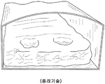
일부 구성에 있어서, 공기는 노의 측벽 또는 노의 문짝에 있는 댐퍼 포트(damper port) 또는 개구를 통해 노에 도입된다. 석탄 베드(coal bed) 위에 있는 크라운 영역에서, 공기는 석탄의 열분해로부터 나오는 휘발성 물질 가스와 연소한다. 그러나, 도 1 내지 도 3을 참고하면, 오븐 챔버(oven chamber)에 유입되는 저온 공기에 작용하는 부력 효과는 석탄의 번아웃(burnout) 및 산출 생산성에서의 손실을 초래할 수 있다. 구체적으로, 도 1에 도시된 바와 같이, 노에 유입되는 저온의 짙은 공기는 고온인 석탄 표면을 향해 내려가게 된다. 상기 공기가 가온되고 상승하여 휘발성 물질과 함께 연소할 수 있게 되기 전에, 및/또는 노 내에서 소산되고 혼합되기 전에, 상기 공기는 석탄 베드의 표면과 접촉하게 되며 연소하여, 도 2에 나타내는 바와 같은 "핫 스팟(hot spot)"을 생성한다. 도 3을 참고하면, 이러한 핫 스팟은, 석탄 베드 표면에 형성되는 오목부에 의해 입증되는 바와 같이 석탄 표면 상에서의 연소 손실(burn loss)을 발생시킨다. 이에 따라, 코크스로에서의 연소 효율을 개선할 필요가 존재한다.In some configurations, air is introduced into the furnace through a damper port or opening in the sidewall of the furnace or the door of the furnace. In the crown area above the coal bed, air burns with volatile gases from the pyrolysis of coal. However, referring to Figures 1 to 3, the buoyancy effect acting on the cold air entering the oven chamber can lead to burnout of the coal and loss of output productivity. Specifically, as shown in Fig. 1, the low-temperature, dense air introduced into the furnace descends toward the high-temperature coal surface. The air comes into contact with the surface of the coal bed before it is allowed to warm up and rise to burn with the volatile material, and / or before being dispersed and mixed in the furnace, Create a "hot spot. &Quot; Referring to FIG. 3, such hot spots cause burn losses on the coal surface, as evidenced by the recesses formed in the surface of the coal bed. Accordingly, there is a need to improve the combustion efficiency in the coke oven.
다수의 코크스화 작업에 있어서, 노의 드래프트(draft)는 업테이크 댐퍼(uptake damper)의 개방 및 폐쇄를 통해 적어도 부분적으로 제어된다. 그러나, 통상적인 코크스화 작업은, 적시에 업테이크 댐퍼 설정을 변경하는 것에 기초한다. 예를 들면, 48 시간 사이클에 있어서, 상기 업테이크 댐퍼는 보통 코크스화 사이클의 대략적으로 첫 24 시간 동안 완전히 개방되도록 설정된다. 상기 업테이크 댐퍼는 이후 코크스화 사이클의 32 시간에 앞서 제1의 부분 억제 위치로 이동하게 된다. 코크스화 사이클의 40 시간에 앞서, 상기 업테이크 댐퍼는 제2의 추가 억제 위치로 이동하게 된다. 48 시간의 코크스화 사이클의 종료 시에, 상기 업테이크 댐퍼는 실질적으로 폐쇄된다. 업테이크 댐퍼를 관리하는 이러한 방식은 융통성이 없는 것으로 입증될 수 있다. 예를 들면, 47 톤을 초과하는 대량의 장전물은, 활짝 개방된 업테이크 댐퍼 설정을 통해 노에 유입되는 공기의 체적에 대해 노 내로 과도하게 많은 휘발성 물질을 방출할 수 있다. 오랜 시구간에 걸친 이러한 휘발성 물질-공기 혼합물의 연소는, 노를 손상시킬 수 있는 NTE 온도를 초과하는 온도 상승을 유발할 수 있다. 이에 따라, NTE 온도를 초과하지 않도록 하면서 코크스로의 장전 중량을 증가시킬 필요가 있다.In many coking operations, the draft of the furnace is at least partially controlled through the opening and closing of the uptake damper. However, conventional coking operations are based on changing timed up-take damper settings. For example, in a 48 hour cycle, the up-take dampers are typically set to fully open for approximately the first 24 hours of the coking cycle. The up-take damper is then moved to the first partial suppression position before 32 hours of the coking cycle. Prior to 40 hours of the coking cycle, the up-take damper is moved to the second additional restraining position. At the end of the 48 hour coking cycle, the up-take dampers are substantially closed. This approach of managing up-take dampers can prove to be inflexible. For example, a large number of charges exceeding 47 tonnes can release excess volatiles into the furnace over the volume of air entering the furnace through a wide open up-take damper setting. Combustion of these volatile-air mixtures over a long period of time can cause a temperature rise above the NTE temperature, which can damage the furnace. Accordingly, it is necessary to increase the loading weight of the coke oven while not exceeding the NTE temperature.
코크스화 프로세스에 의해 발생되는 열은 보통 코크스 플랜트와 연관된 열 회수 증기 발전기(HRSG; Heat Recovery Steam Generators)에 의해 동력으로 변환된다. 비효율적인 연소 프로파일 관리는, 휘발성 물질 가스가 노에서 연소되지 않고 공통 터널(common tunnel)로 보내지는 결과를 초래할 수 있다. 이는 코크스화 프로세스를 위해 코크스로에 의해 이용될 수 있는 열을 낭비하게 된다. 연소 프로파일의 부적절한 관리는 또한 코크스 생산 속도를 더욱 저하시킬 수 있을 뿐만 아니라 코크스 플랜트에 의해 생산되는 코크스의 품질을 저하시킬 수 있다. 예를 들면, 코크스로에서 업테이크(uptake)를 관리하는 다수의 현존하는 방법은, 코크스화 사이클에 걸쳐 유지될 수 있는 솔 플루 온도(sole flue temperature) 범위를 한정하며, 이는 생산 속도 및 코크스 품질에 악영향을 줄 수 있다. 이에 따라, 코크스 플랜트의 작업 및 생산을 최적화하기 위해 코크스로의 연소 프로파일이 관리되는 방식을 개선할 필요가 있다.Heat generated by the coking process is converted to power by heat recovery steam generators (HRSGs) associated with the coke plant. Inefficient combustion profile management can result in volatile gases being sent to a common tunnel without burning in the furnace. Which wastes heat that can be utilized by the coke oven for the coking process. Inadequate management of the combustion profile may further degrade the coke production rate as well as reduce the quality of the coke produced by the coke plant. For example, many existing methods of managing uptakes in coke ovens define a range of sole flue temperatures that can be maintained over the coking cycle, which can include production rate and coke quality Can be adversely affected. Accordingly, there is a need to improve the manner in which the combustion profile of the coke oven is managed to optimize the operation and production of the coke plant.
본 발명의 과제는, 대체로 코크스 플랜트(coke plant)의 작업 및 생산(output)을 최적화하는 코크스로 연소 프로파일(coke oven burn profile) 및 방법과 시스템을 제공하는 것이다.It is an object of the present invention to provide a coke oven burn profile and method and system that optimizes the operation and output of a coke plant.
본 발명의 일 실시예에 따르면,According to an embodiment of the present invention,
수평 열회수 코크스로 연소 프로파일(horizontal heat recovery coke oven burn profile)의 제어 방법으로서,A method of controlling a horizontal heat recovery coke oven burn profile,
수평 열회수 코크스로의 오븐 챔버(oven chamber) 내로 석탄 베드(bed of coal)를 장전하는 단계로서, 상기 오븐 챔버는, 오븐 플로어(oven floor), 대향하는 오븐 도어(oven door), 대향하는 오븐 도어들 사이에서 오븐 플로어로부터 상방으로 연장되는 대향 측벽, 및 오븐 플로어 위에 위치 설정되는 오븐 크라운(oven crown)에 의해 적어도 부분적으로 형성되는 것인 단계;Loading a bed of coal into an oven chamber of a horizontal heat recovery coke oven, the oven chamber comprising an oven floor, an opposing oven door, an opposing oven door An opposing sidewall extending upwardly from the oven floor between the oven floor and an oven crown positioned over the oven floor;
상기 수평 열회수 코크스로에 대해 외측의 환경과 유체 연통되게 오븐 챔버를 배치하도록 위치 설정되는, 적어도 하나의 공기 유입구를 통해 오븐 챔버 내로 공기가 유입되도록, 오븐 챔버 상의 부압 드래프트(negative pressure draft)를 생성하는 단계;Creates a negative pressure draft on the oven chamber so that air is introduced into the oven chamber through at least one air inlet that is positioned to place the oven chamber in fluid communication with the outside environment for the horizontal heat recovery coke oven ;
휘발성 물질이 석탄 베드로부터 방출되어 공기와 혼합되고 오븐 챔버 내에서 적어도 부분적으로 연소되어 오븐 챔버 내에서 열을 발생시키도록, 석탄 베드의 탄화 사이클을 개시하는 단계로서,Initiating a carbonization cycle of the coal bed such that volatiles are released from the coal bed to be mixed with the air and at least partially combusted within the oven chamber to generate heat in the oven chamber,
상기 부압 드래프트는 휘발성 물질을 오븐 플로어 아래에 있는 적어도 하나의 솔 플루(sole flue) 내로 유입시키고, 휘발성 물질의 적어도 일부는 솔 플루 내에서 연소하여, 오븐 플로어를 통해 석탄 베드로 적어도 부분적으로 전달되는 열을 솔 플루 내에서 발생시키며,The negative pressure draft introduces volatiles into at least one sole flue below the oven floor and at least a portion of the volatile material burns in the sole fl ow so that the heat transferred at least partially through the oven floor to the coal bed Lt; RTI ID = 0.0 >
상기 부압 드래프트에 의해 적어도 하나의 솔 플루로부터 배기 가스가 인출되는 것인 단계;The exhaust gas is drawn from at least one sol-gel by the negative pressure draft;
상기 탄화 사이클에 걸쳐 오븐 챔버 내에서 복수의 온도 변동을 탐지하는 단계;Detecting a plurality of temperature fluctuations in the oven chamber over the carbonization cycle;
오븐 챔버 내에서의 복수의 온도 변동에 기초하여, 복수의 개별적인 유동 저감 단계에 걸쳐 부압 드래프트를 감소시키는 단계Reducing the negative pressure draft over a plurality of individual flow abatement steps based on a plurality of temperature fluctuations in the oven chamber,
를 포함하는 방법이 제시된다.A method is disclosed.
본 발명의 다른 실시예에 따르면,According to another embodiment of the present invention,
수평 열회수 코크스로 연소 프로파일(horizontal heat recovery coke oven burn profile)을 제어하기 위한 시스템으로서,A system for controlling a horizontal heat recovery coke oven burn profile,
오븐 플로어, 대향하는 오븐 도어, 대향하는 오븐 도어 사이에서 오븐 플로어로부터 상방으로 연장되는 대향 측벽, 오븐 플로어 위에 위치 설정되는 오븐 크라운, 및 오븐 챔버와 유체 연통하며 오븐 플로어 아래에 있는 적어도 하나의 솔 플루에 의해 적어도 부분적으로 형성되는 오븐 챔버를 갖춘 수평 열회수 코크스로;An oven floor, an opposing oven door, an opposing sidewall extending upwardly from the oven floor between the opposing oven doors, an oven crowning positioned over the oven floor, and at least one breeze fluid in fluid communication with the oven chamber, A horizontal heat recovery coke having an oven chamber formed at least in part by the heat recovery coke;
상기 오븐 챔버 내에 배치되는 온도 센서;A temperature sensor disposed in the oven chamber;
상기 수평 열회수 코크스로에 대해 외부의 환경과 유체 연통되게 오븐 챔버를 배치하도록 위치 설정되는 적어도 하나의 공기 유입구;At least one air inlet positioned to place the oven chamber in fluid communication with the external environment for the horizontal heat recovery coke oven;
적어도 하나의 상기 솔 플루와 유체 연통하는 업테이크 댐퍼를 갖춘 적어도 하나의 업테이크 채널로서,At least one up-take channel having an up-take damper in fluid communication with at least one said sol-
상기 업테이크 댐퍼는 개방 위치와 폐쇄 위치 사이에서 선택적으로 이동 가능하고,The up-take damper is selectively movable between an open position and a closed position,
복수의 유동 저감 단계에 걸쳐 부압 드래프트가 감소되는 것인 적어도 하나의 업테이크 채널;At least one up-take channel wherein the negative pressure draft is reduced over a plurality of flow abatement steps;
상기 업테이크 댐퍼에 작동 가능하게 결합되는 제어기로서, 오븐 챔버 내의 온도 센서에 의해 탐지되는 복수의 다양한 온도에 기초하여, 탄화 사이클에 걸쳐 복수의 증대되는 유동 억제 위치를 통해 업테이크 댐퍼를 이동시키도록 되어 있는 제어기A controller operatively coupled to the up-take damper, the controller operative to move the up-take damper through a plurality of increased flow restraint positions over the carbonization cycle, based on a plurality of various temperatures detected by a temperature sensor in the oven chamber The controller
를 포함하는 시스템이 제시된다.Is presented.
본 발명의 또 다른 실시예에 따르면,According to another embodiment of the present invention,
수평 열회수 코크스로 연소 프로파일(horizontal heat recovery coke oven burn profile)의 제어 방법으로서,A method of controlling a horizontal heat recovery coke oven burn profile,
수평 열회수 코크스로의 오븐 챔버 내에서 석탄 베드의 탄화 사이클을 개시하는 단계;Initiating a carbonization cycle of the coal bed in an oven chamber of a horizontal heat recovery coke oven;
상기 탄화 사이클에 걸쳐 오븐 챔버 내에서 복수의 온도 변동을 탐지하는 단계;Detecting a plurality of temperature fluctuations in the oven chamber over the carbonization cycle;
상기 오븐 챔버 내에서의 복수의 온도 변동에 기초하여, 복수의 개별적인 유동 저감 단계에 걸쳐 수평 열회수 코크스로에서의 부압 드래프트를 감소시키는 단계Reducing the negative pressure draft in the horizontal heat recovery coke oven over a plurality of individual flow reduction steps, based on a plurality of temperature variations in the oven chamber
를 포함하는 방법이 제시된다.A method is disclosed.
바람직한 실시예를 비롯한, 본 발명의 비한정적이고 비포괄적인 실시예가 이하의 도면을 참고로 설명되며, 달리 특정되지 않는 한, 다양한 도면 전반에 걸쳐 동일한 도면부호는 동일한 부분을 가리킨다.
도 1은 코크스로의 대향 단부에 도어 공기 유입구를 갖는 종래 기술의 코크스로의 부분 등각 투시도를 도시한 것이며, 공기가 노로 유입되고 부력으로 인해 석탄 표면을 향해 가라앉는 한 가지 방식을 도시한 것이다.
도 2는 종래 기술의 코크스로의 부분 등각 투시도를 도시한 것이며, 석탄 베드 표면과 공기 스트림 사이의 직접 접촉에 의해 형성되는 코크스 베드 표면의 번아웃에 관한 영역을 도시한 것이다.
도 3은 코크스로의 부분 단부 확대도를 도시한 것이며, 석탄 베드의 표면과 공기 스트림 사이의 직접 접촉으로 인해 코크스 베드 표면 상에 형성되는 딤플(dimple)의 예를 도시한 것이다.
도 4는 본 기술의 실시예에 따라 구성되는, 수평 열회수 코크스 플랜트의 일부에 관한 부분 등각 절개도를 도시한 것이다.
도 5는 본 기술의 실시예에 따라 구성되는, 수평 열회수 코크스로에 관한 단면도를 도시한 것이다.
도 6은 본 기술의 실시예에 따라 구성되는 크라운 공기 유입구(crown air inlet)를 갖춘 코크스로에 관한 부분 등각 투시도를 도시한 것이다.
도 7은 도 6에 도시된 코크스로의 부분 단부도를 도시한 것이다.
도 8은 본 기술의 실시예에 따라 구성되는 공기 유입구의 상부 평면도를 도시한 것이다.
도 9는 48 시간의 코크스화 사이클 전반에 걸쳐 특정한 시각에 어떤 위치에서 업테이크가 배치되어야 하는지를 나타내는 통상적인 업테이크 작업표를 도시한 것이다.
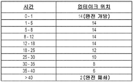
도 10은 본 기술의 실시예에 따른 업테이크 작업표를 도시한 것이며, 48 시간의 코크스화 사이클 전반에 걸쳐 특정 코크스로 크라운 온도 범위에 대해 어떤 위치에서 업테이크가 배치되어야 하는지를 나타낸다.
도 11은 본 기술의 실시예에 따라 생성되는 코크스 베드를 수용하는 코크스로의 부분 단부도를 도시한 것이다.
도 12는 본 기술의 실시예에 따른 연소 프로파일 및 통상적인 연소 프로파일에 대해, 시간에 따른 코크스로 크라운 온도를 비교한 그래프를 도시한 것이다.
도 13은 본 기술의 실시예에 따른 연소 프로파일 및 통상적인 연소 프로파일에 대해, 톤수(tonnage), 코크스화 시간, 및 코크스화 속도를 비교한 그래프를 도시한 것이다.
도 14는 본 기술의 실시예에 따른 연소 프로파일 및 통상적인 연소 프로파일에 대해, 시간에 따른 코크스로의 크라운 온도를 비교한 그래프를 도시한 것이다.
도 15는 본 기술의 실시예에 따른 연소 프로파일 및 통상적인 연소 프로파일에 대해, 시간에 따른 코크스로의 솔 플루 온도를 비교한 다른 그래프를 도시한 것이다.The non-limiting, non-exhaustive embodiments of the present invention, including the preferred embodiment, are described with reference to the following drawings, wherein like reference numerals refer to like parts throughout the various views unless otherwise specified.
Figure 1 shows a partial isometric view of a prior art coke oven with a door air inlet at the opposite end of the coke oven and illustrates one way in which air is introduced into the furnace and sinks towards the coal surface due to buoyancy.
Figure 2 shows a partial isometric view of a prior art coke oven and illustrates the area of the burnout of the coke bed surface formed by direct contact between the coal bed surface and the air stream.
Figure 3 shows a partial end enlarged view of the coke oven and shows an example of a dimple formed on the coke bed surface due to direct contact between the surface of the coal bed and the air stream.
Figure 4 shows a partial isometric view of a portion of a horizontal heat recovery coke plant constructed in accordance with an embodiment of the present technique.
Figure 5 shows a cross-sectional view of a horizontal heat recovery coke oven constructed in accordance with an embodiment of the present technique.
Figure 6 shows a partial isometric perspective view of a coke oven with a crown air inlet constructed in accordance with an embodiment of the present technique.
Fig. 7 shows a partial end view of the coke oven shown in Fig. 6. Fig.
Figure 8 shows a top plan view of an air inlet constructed in accordance with an embodiment of the present technique.
Figure 9 shows a typical up-take task table showing at which position an up-take should be placed at a particular time throughout the 48 hour coking cycle.
Figure 10 shows an uptake work table according to an embodiment of the present technology and shows where the uptake should be placed for a particular coke crown temperature range over a 48 hour coking cycle.
Figure 11 shows a partial end view of a coke oven receiving a resulting coke bed in accordance with an embodiment of the present technique.
12 shows a graph comparing the coke-crown temperature over time for the combustion profile and the typical combustion profile according to embodiments of the present technology.
Figure 13 shows a graph comparing the tonnage, coking time, and coking rate for the combustion profile and typical combustion profile according to embodiments of the present technology.
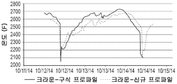
Figure 14 shows a graph comparing the crown temperature of the coke oven over time with respect to the combustion profile and the typical combustion profile according to embodiments of the present technology.
FIG. 15 shows another graph comparing solublature temperatures to cokes over time for combustion profiles and typical combustion profiles according to embodiments of the present technology.
본 기술은 대체로 코크스로(coke oven), 예컨대 수평 열회수 노(HHR oven; horizontal heat recovery oven)에 관한 연소 프로파일(burn profile)을 최적화하기 위한 시스템 및 방법에 관한 것이다. 다양한 실시예에 있어서, 상기 연소 프로파일은 코크스로에서의 공기 분포를 제어함으로써 적어도 부분적으로 최적화된다. 일부 실시예에 있어서, 상기 공기 분포는 코크스로에서의 온도 판독에 따라 제어된다. 구체적인 실시예에 있어서, 상기 시스템은 코크스로의 크라운 온도(crown temperature)를 모니터링한다. 오븐 크라운(oven crown)과 솔 플루(sole flue) 사이에서의 가스의 전달은, 코크스화 사이클 전반에 걸쳐 솔 플루 온도를 상승시키기 위해 최적화된다. 일부 실시예에 있어서, 본 기술은, 더 많은 휘발성 물질 가스를 전달하고 이 휘발성 물질을 솔 플루에서 연소시킴으로써 NTE 온도를 초과하지 않으면서 코크스로의 장전 중량을 증가시키는 것을 가능하게 한다. 본 기술의 실시예는, 오븐 플로어(oven floor) 위에 위치 설정되는 복수 개의 크라운 공기 유입구(crown air inlet)를 갖춘 공기 분배 시스템을 포함한다. 상기 크라운 공기 유입구는, 베드의 번아웃을 감소시키는 방식으로 오븐 챔버 내로 공기를 도입하도록 구성된다.The present technique relates generally to a system and method for optimizing a burn profile for a coke oven, such as a horizontal heat recovery oven (HHR oven). In various embodiments, the combustion profile is at least partially optimized by controlling the air distribution in the coke oven. In some embodiments, the air distribution is controlled according to temperature readings in the coke oven. In a specific embodiment, the system monitors the crown temperature of the coke oven. The transfer of gas between the oven crown and the sole flue is optimized to raise the sole flue temperature throughout the coking cycle. In some embodiments, the technique makes it possible to increase the loaded weight to the coke without exceeding the NTE temperature by delivering more volatile gases and burning the volatile material in the sol-flute. Embodiments of the present technology include an air distribution system having a plurality of crown air inlets positioned on an oven floor. The crown air inlet is configured to introduce air into the oven chamber in a manner that reduces burnout of the bed.
본 기술의 여러 가지 실시예에 관한 구체적인 세부사항은 도 4 내지 도 15를 참고하여 이하에서 설명된다. 코크스화 설비, 구체적으로 공기 분배 시스템, 자동화된 제어 시스템, 및 코크스로와 종종 관련되는 널리 공지된 구조 및 시스템을 설명하는 다른 세부사항은, 본 기술의 다양한 실시예에 관한 설명을 불필요하게 복잡하게 하는 것을 피하고자 이하의 개시내용에는 기술되어 있지 않다. 도면에 도시된 세부사항, 치수, 각도 및 다른 특징 중 다수는 단지 본 기술의 구체적인 실시예를 예시하려는 것이다. 이에 따라, 다른 실시예는 본 기술의 사상 또는 범위로부터 벗어나지 않으면서 다른 세부사항, 치수, 각도 및 특징을 나타낼 수 있다. 따라서, 당업자라면, 본 기술이 추가적인 요소를 갖춘 다른 실시예로도 가능할 수 있거나, 또는 본 기술이 도 4 내지 도 15를 참고하여 이하에 설명 및 도시된 특징부들 중 여러 가지를 포함하지 않으면서 다른 실시예로 가능할 수 있다는 것을 이해할 것이다.Specific details of various embodiments of the present technology will be described below with reference to Figs. 4 to 15. Fig. Other details describing coking facilities, specifically air distribution systems, automated control systems, and well known structures and systems often associated with coke oven, make the description of various embodiments of the technology unnecessarily complex And is not described in the following disclosure. Many of the details, dimensions, angles, and other features shown in the drawings are merely illustrative of specific embodiments of the present technique. Accordingly, other embodiments may represent other details, dimensions, angles, and features without departing from the spirit or scope of the technology. Accordingly, those skilled in the art will appreciate that the present technique may be possible in other embodiments with additional elements, or that the present technique may be applied to other embodiments without including any of the features described and illustrated below with reference to FIGS. It will be appreciated that embodiments may be possible.
이하의 추가적인 상세한 설명에 기술된 바와 같이, 여러 가지 실시예에 있어서, 개별적인 코크스로(100)는 석탄의 휘발성 물질을 연소시키기 위해 부압 오븐 챔버(negative pressure oven chamber) 내로 외부 공기를 허용하도록 구성되는 하나 이상의 공기 유입구를 포함할 수 있다. 상기 공기 유입구는 오븐 챔버 내에서 공기를 안내하기 위한, 순환시키기 위한, 및/또는 분배하기 위한 하나 이상의 공기 분배기와 함께 혹은 이러한 공기 분배기 없이 사용될 수 있다. 본원에서 사용될 때 용어 "공기"는 분위기 공기, 산소, 산화제, 질소, 질소 산화물, 희석제, 연소 가스, 공기 혼합물, 산화제 혼합물, 연도 가스, 재순환된 통풍 가스, 증기, 첨가제를 함유한 가스, 불활성 물질, 열 흡수제, 물방울과 같은 액상 재료, 가스 캐리어(gaseous carrier)를 통해 분무화된 액적과 같은 다상 재료, 흡입된 액체 연료, 가스 캐리어 스트림 내의 분무화된 액체 헵탄, 천연 가스 또는 수소와 같은 연료, 냉각된 가스, 다른 가스, 액체 또는 고체 혹은 이들 재료의 조합을 포함할 수 있다. 다양한 실시예에 있어서, 공기 유입구 및/또는 공기 분배기는 수동 제어 또는 자동화된 최신 제어 시스템에 응답하여 기능할 수 있다(즉, 개방, 폐쇄, 공기 분배 패턴의 변경 등을 행할 수 있음). 공기 유입구 및/또는 공기 분배기는 전용 최신 제어 시스템 상에서 작동할 수도 있고, 공기 유입구 및/또는 공기 분배기뿐만 아니라 업테이크 댐퍼, 솔 플루 댐퍼(sole flue damper), 및/또는 코크스로 시스템 내의 다른 공기 분배 경로를 조절하는 보다 광범위한 드래프트 제어 시스템(draft control system)에 의해 제어될 수 있다.As described in the following additional detailed description, in various embodiments, the
도 4는 본 기술의 실시예에 따라 구성되는, 수평 열회수 코크스 플랜트의 일부에 관한 부분 절개도를 도시한 것이다. 도 5는 본 기술의 실시예에 따라 구성되는, 수평 열회수 코크스로(100)에 관한 단면도를 도시한 것이다. 각각의 노(100)는, 오븐 플로어(102), 푸셔 사이드 오븐 도어(pusher side oven door; 104), 푸셔 사이드 오븐 도어(104)에 대향하는 코크스 사이드 오븐 도어(coke side oven door; 106), 오븐 플로어(102)로부터 상향으로 연장되고 푸셔 사이드 오븐 도어(104)와 코크스 사이드 오븐 도어(106) 사이에서 연장되는 대향 측벽(108), 및 오븐 챔버(112)의 개방 공동의 상부 표면을 형성하는 크라운(110)에 의해 형성되는 개방 공동을 포함한다. 오븐 챔버(112) 내부에서의 공기 흐름 및 압력을 제어하는 것은, 코크스화 사이클의 효율적인 작동에 있어서 중요한 역할을 한다. 이에 따라, 도 6 및 도 7을 참고하면, 본 기술의 실시예는, 오븐 챔버(112) 내로 제1 연소 공기를 허용하는 하나 이상의 크라운 공기 유입구(114)를 포함한다. 일부 실시예에 있어서, 노(100) 외부의 분위기 환경과 개방식으로 유체 연통되는 오븐 챔버(112)를 선택적으로 배치하는 방식으로 다수의 크라운 공기 유입구(114)가 크라운(110)을 관통하게 된다. 도 8을 참고하면, 업테이크 엘보우 공기 유입구(uptake elbow air inlet; 115)의 예는, 공기 유입구를 통한 공기 흐름의 양을 변경시키기 위해 완전 개방과 완전 폐쇄 사이에 있는 다수의 위치 중 임의의 위치에 위치 설정될 수 있는 공기 댐퍼(air damper; 116)를 갖는 것으로 도시되어 있다. 도어 공기 유입구 및 크라운 공기 유입구(114)를 비롯한 다른 오븐 공기 유입구(oven air inlet)는 마찬가지 방식으로 작동하는 공기 댐퍼(116)를 포함한다. 업테이크 엘보우 공기 유입구(115)는 공통 터널(128) 내로 공기를 허용하도록 위치 설정되는 반면, 도어 공기 유입구 및 크라운 공기 유입구(114)는 오븐 챔버(112) 내로의 공기 흐름의 양을 변경시킨다. 본 기술의 실시예는 오븐 챔버(112) 내로 제1 연소 공기를 제공하기 위해 오직 크라운 공기 유입구(114)만을 사용할 수 있지만, 본 기술의 양태로부터 벗어나지 않으면서 특정 실시예에서는 도어 공기 유입구와 같은 다른 유형의 공기 유입구도 사용될 수 있다.Figure 4 shows a partial cut-away view of a portion of a horizontal heat recovery coke plant constructed in accordance with an embodiment of the present technique. 5 illustrates a cross-sectional view of a horizontal heat
작업 중에, 오븐 챔버(112) 내부에 위치 설정되는 석탄으로부터 나오는 휘발성 가스는 크라운에 수집되며, 일 측벽 또는 양 측벽(108)에 형성되는 다운코머 채널(downcomer channel; 118) 내로 하류로 유도된다. 다운코머 채널(118)은, 오븐 플로어(102) 아래에 위치 설정되는 솔 플루(120)와 오븐 챔버(112)를 유체 연결한다. 솔 플루(120)는 오븐 플로어(102) 아래에서 빙 돌아가는 경로를 형성한다. 석탄으로부터 나오는 휘발성 가스는 솔 플루(120)에서 연소될 수 있고, 이에 따라 석탄이 코크스로 환원되는 것을 지원하는 열을 발생시키게 된다. 다운코머 채널(118)은 일 측벽(108) 또는 양 측벽에 형성된 업테이크 채널(122)에 유체 연결된다. 제2 공기 유입구(124)가 솔 플루(120)와 대기 사이에 마련될 수 있으며, 제2 공기 유입구(124)는, 솔 플루(120) 내로의 제2 공기 흐름의 양을 변경시키기 위해 완전 개방과 완전 폐쇄 사이에 있는 다수의 위치 중 임의의 위치에 위치 설정될 수 있는 제2 공기 댐퍼(126)를 포함할 수 있다. 업테이크 채널(122)은 하나 이상의 업테이크 덕트(130)에 의해 공통 터널(128)에 유체 연결된다. 제3 공기 유입구(132)는 업테이크 덕트(130)와 대기 사이에 마련될 수 있다. 제3 공기 유입구(132)는, 업테이크 덕트(130) 내로의 제3 공기 흐름의 양을 변경시키기 위해 완전 개방과 완전 폐쇄 사이에 있는 다수의 위치 중 임의의 위치에 위치 설정될 수 있는 제3 공기 댐퍼(134)를 포함할 수 있다.During operation, volatile gases from the coal positioned within the
각각의 업테이크 덕트(130)는, 업테이크 덕트(130)를 통한 노(100) 내에서의 가스 흐름을 제어하기 위해 사용될 수 있는 업데이트 댐퍼(136)를 포함한다. 업테이크 댐퍼(136)는, 노(100) 내에서 오븐 드래프트(oven draft)의 양을 변경시키기 위해 완전 개방과 완전 폐쇄 사이에 있는 다수의 위치 중 임의의 위치에 위치 설정될 수 있다. 업테이크 댐퍼(136)는 임의의 자동 제어식 또는 수동 제어식 유동 제어 디바이스 혹은 오리피스 차단 디바이스(예컨대, 임의의 플레이트, 밀봉부, 차단부 등)를 포함할 수 있다. 적어도 일부 실시예에 있어서, 업테이크 댐퍼(136)는 "폐쇄"를 나타내는 0과 2 그리고 "완전 개방"을 나타내는 14 사이의 유동 위치에 설정된다. 심지어 "폐쇄" 위치에 있어서, 또한 업테이크 댐퍼(136)는 소량의 공기가 업테이크 덕트(130)를 통과하도록 허용할 수 있는 것을 고려할 수 있다. 마찬가지로, 업테이크 댐퍼(136)가 "완전 개방" 위치에 있을 때 업테이크 댐퍼(136)의 작은 부분이 업테이크 덕트(130)를 통과하는 공기의 흐름 내에 적어도 부분적으로 위치 설정될 수 있는 것을 고려할 수 있다. 업테이크 댐퍼는 0과 14 사이에서 거의 무한한 개수의 위치를 취할 수 있다는 것을 이해할 것이다. 도 9 및 도 10을 참고하면, 유동 억제의 수준을 높이는, 업테이크 댐퍼(136)에 관한 일부 예시적인 설정은, 12, 10, 8 및 6을 포함한다. 일부 실시예에 있어서, 유동 위치 번호는 단순히 14인치 업테이크 덕트의 사용을 반영하고 있으며, 각각의 번호는 개방되는 업테이크 덕트(130)의 수준을 인치 단위로 나타낸 것이다. 다른 방식으로는, 0 내지 14의 유동 위치 번호 스케일은 개방과 폐쇄 사이에서의 증분 설정으로서 단순하게 이해될 수 있다는 것을 이해할 수 있을 것이다.Each up-
본원에서 사용될 때, "드래프트(draft)"는 대기에 대한 부압을 나타낸다. 예를 들면, 0.1 인치의 물의 드래프트는 대기압 아래로 0.1 인치의 물의 압력을 나타낸다. 물의 인치 수는 압력에 관한 비-SI 단위이며, 코크스 플랜트 내의 다양한 위치에서의 드래프트를 설명하기 위해 통상적으로 사용된다. 일부 실시예에 있어서, 드래프트는 약 0.12 인치의 물 내지 약 0.16 인치의 물의 범위이다. 드래프트가 증가하면, 또는 달리 더 커지면, 압력은 대기압 아래로 더 이동하게 된다. 드래프트가 감소하거나 떨어지면, 또는 달리 더 작아지거나 낮아지면, 압력은 대기압을 향해 이동하게 된다. 업테이크 댐퍼(136)를 이용하여 오븐 드래프트를 제어함으로써, 크라운 공기 유입구(114)로부터 노(100) 내로의 공기 흐름뿐만 아니라 노(100) 내로의 공기 누출도 제어될 수 있다. 보통, 도 5에 도시된 바와 같이, 개별적인 노(100)는 2개의 업테이크 덕트(130) 및 2개의 업테이크 댐퍼(136)를 포함하지만, 2개의 업테이크 덕트 및 2개의 업테이크 댐퍼의 사용은 필수적인 것은 아니며, 시스템은 2개의 업테이크 덕트 및 2개의 업테이크 댐퍼가 아닌 1개의 업테이크 덕트 및 업테이크 댐퍼 또는 3개 이상의 업테이크 덕트 및 업테이크 댐퍼를 사용하도록 구성될 수 있다.As used herein, "draft" refers to the negative pressure against the atmosphere. For example, a draft of 0.1 inch of water represents a pressure of 0.1 inches of water below atmospheric pressure. The number of inches of water is a non-SI unit for pressure and is typically used to describe drafts at various locations within a coke plant. In some embodiments, the draft ranges from about 0.12 inches of water to about 0.16 inches of water. As the draft increases, or otherwise increases, the pressure moves further under the atmospheric pressure. If the draft decreases or falls, or otherwise becomes smaller or lower, the pressure will move toward atmospheric pressure. By controlling the oven draft using the up-
작업 중에, 우선 석탄을 오븐 챔버(112) 내로 장전하고, 산소 고갈 환경에서 석탄을 가열하며, 석탄의 휘발성 성분을 날려버리고, 이후 방출되는 열을 포획 및 이용하기 위해 노(100) 내에서 휘발성 물질을 산화시킴으로써 노(100) 내에서 코크스가 생성된다. 석탄의 휘발성 물질은 긴 코크스화 사이클에 걸쳐 노(100) 내에서 산화되며, 석탄의 코크스로의 탄화를 재생식으로 강제하기 위한 열을 방출한다. 코크스화 사이클은, 푸셔 사이드 오븐 도어(104)가 개방될 때 개시되며, 석탄은 석탄 베드를 형성하는 방식으로 오븐 플로어(102) 내로 장전된다. 노로부터의 열(이전 코크스화 사이클로 인한 열)은 탄화 사이클이 개시되도록 한다. 다수의 실시예에 있어서, 코크스화 프로세스에 의해 생성되는 연료 이외의 다른 추가적인 연료는 사용되지 않는다. 석탄 베드로의 총 열 전달의 대략 절반이 석탄 베드의 발광 화염(luminous flame) 및 발광하는 오븐 크라운(oven crown; 110)으로부터 석탄 베드의 상부 표면 상으로 아래로 방출된다. 상기 총 열 전달의 나머지 절반은, 솔 플루(120)에서의 가스의 휘발 작용으로부터 대류식으로 가열되는 오븐 플로어(102)로부터의 전도에 의해 석탄 베드에 전달된다. 이러한 방식으로, 석탄 입자의 소성 흐름(plastic flow)의 탄화 프로세스 "파동(wave)" 및 고강도 응집 코크스의 형성은 석탄 베드의 상부 경계 및 하부 경계 양자 모두로부터 진행된다.During operation, first the coal is loaded into the
보통, 각각의 노(100)는 부압에서 작동하며, 이에 따라 공기는 노(100)와 대기 사이의 차압으로 인해 환원 프로세스 동안 노 내로 유입된다. 연소를 위한 제1 공기가 오븐 챔버(112)에 추가되어 부분적으로 석탄의 휘발성 물질을 산화시키지만, 석탄으로부터 방출되는 휘발성 물질의 단지 일부만이 오븐 챔버(112) 내에서 연소되도록 하기 위해 이러한 제1 공기의 양은 제어되며, 이에 따라 오븐 챔버(112) 내에서 연소 엔탈피의 단지 일부만이 방출된다. 다양한 실시예에 있어서, 제1 공기는 크라운 공기 유입구(114)를 통해 석탄 베드 위로 오븐 챔버(112) 내에 도입되는데, 이때 제1 공기의 양은 크라운 공기 댐퍼(116)에 의헤 제어된다. 다른 실시예에 있어서, 본 기술의 양태로부터 벗어나지 않으면서 다양한 유형의 공기 유입구가 사용될 수 있다. 에를 들면, 제1 공기는 공기 유입구, 댐퍼 포트, 및/또는 노 측벽 또는 문짝에 있는 개구를 통해 노에 도입될 수 있다. 사용되는 공기 유입구의 유형과는 상관 없이, 상기 공기 유입구는 오븐 챔버(112) 내부에서 원하는 작동 온도를 유지하기 위해 사용될 수 있다. 공기 유입구 댐퍼의 사용을 통해 오븐 챔버(112) 내로의 제1 공기 흐름을 증가시키거나 감소시키면, 오븐 챔버(112)에서의 휘발성 물질의 연소가 증가되거나 감소되며, 이에 따라 온도가 높아지거나 낮아지게 된다.Typically, each
도 6 및 도 7을 참고하면, 본 기술의 실시예에 따라 크라운(110)을 통해 오븐 챔버(112) 내로 연소 공기를 도입하도록 구성되는 크라운 공기 유입구(114)가 코크스로(100)에 마련될 수 있다. 일 실시예에 있어서, 노의 길이를 따라 푸셔 사이드 오븐 도어(104)와 노(100)의 중간점 사이에 3개의 크라운 공기 유입구(114)가 위치 설정된다. 마찬가지로, 코크스 사이드 오븐 도어(106)와 노(100)의 중간점 사이에 3개의 크라운 공기 유입구(114)가 위치 설정된다. 그러나, 노의 길이를 따라 다양한 위치에서 오븐 크라운(110)을 통해 하나 이상의 크라운 공기 유입구(114)가 배치될 수 있다는 것을 고려할 수 있다. 크라운 공기 유입구의 선택된 개수 및 위치 설정은 적어도 부분적으로 노(100)의 구성 및 용도에 따라 좌우된다. 각각의 크라운 공기 유입구(114)는, 오븐 챔버(112) 내로의 공기 흐름의 양을 변경시키기 위해 완전 개방과 완전 폐쇄 사이에 있는 다수의 위치 중 임의의 위치에 위치 설정될 수 있는 공기 댐퍼(116)를 포함할 수 있다. 일부 실시예에 있어서, 공기 댐퍼(116)는 "완전 폐쇄" 위치에서 또한 소량의 분위기 공기가 크라운 공기 유입구(114)를 통해 오븐 챔버 내로 통과하는 것을 가능하게 한다. 이에 따라, 도 8을 참고하면, 크라운 공기 유입구(114), 업테이크 엘보우 공기 유입구(115) 또는 도어 공기 유입구의 다양한 실시예는, 특정한 공기 유입구의 개방된 상측 단부 부분에 탈착 가능하게 고정될 수 있는 캡(cap; 117)을 포함할 수 있다. 캡(117)은 기후 요소(예컨대, 비 및 눈), 추가적인 분위기 공기, 및 다른 외부 물질이 공기 유입구를 통과하는 것을 실질적으로 방지할 수 있다. 코크스로(100)는 오븐 챔버(112) 내로 공기 흐름을 채널링(channeling)/분배하도록 구성되는 하나 이상의 분배기를 더 포함할 수 있다는 것을 고려할 수 있다.6 and 7, a
다양한 실시예에 있어서, 크라운 공기 유입구(114)는, 다른 공기 유입구, 예컨대 보통 오븐 도어 내에 위치하는 것과 같은 공기 유입구가 작동하게 되는 방식으로 코크스화 사이클의 많은 과정에 걸쳐 오븐 챔버(112) 내로 분위기 공기를 도입하도록 작동하게 된다. 그러나, 크라운 공기 유입구(114)의 사용은, 오븐 크라운 전반에 걸쳐 공기의 더욱 균일한 분포를 제공하며, 이는 더욱 양호한 연소, 솔 플루(120)에서의 보다 높은 온도, 및 시간의 경과에 따른 이후 크로스(cross)를 제공하는 것으로 확인되었다. 노(100)의 크라운(110)에서의 공기의 균일한 분포는, 공기가 석탄 베드의 표면에 접촉할 가능성을 감소시키며, 도 3에 도시된 바와 같이, 석탄 표면 상에서의 연소 손실을 발생시키는 핫 스팟이 발생될 가능성을 감소시킨다. 오히려, 크라운 공기 유입구(114)는 이러한 핫 스팟의 발생을 실질적으로 감소시켜, 도 11에 도시된 바와 같이, 석탄 베드가 코크스화할 때 균일한 석탄 베드 표면(140)이 생성되게 한다. 구체적인 용도의 실시예에 있어서, 각각의 크라운 공기 유입구(114)의 공기 댐퍼(116)는 서로에 대해 유사한 위치에 설정된다. 이에 따라, 하나의 공기 댐퍼(116)가 완전 개방되어 있는 경우, 모든 공기 댐퍼(116)는 완전 개방 위치에 배치되게 되고, 하나의 공기 댐퍼(116)가 반 개방 위치에 설정되면, 모든 공기 댐퍼(116)가 반 개방 위치에 설정되게 된다. 그러나, 구체적인 실시예에 있어서, 공기 댐퍼(116)들은 서로 독립적으로 변경될 수 있다. 다양한 실시예에 있어서, 크라운 공기 유입구(114)의 공기 댐퍼(116)는, 노(100)가 장전된 후에 또는 노(100)가 장전되기 직전에 신속하게 개방된다. 3/4 개방 위치로의 공기 댐퍼(116)의 제1 조정은, 제1 도어 구멍 연소가 보통 발생하는 시점에 행해진다. 1/2 개방 위치로의 공기 댐퍼(116)의 제2 조정은, 제2 도어 구멍 연소가 발생하는 시점에 행해진다. 추가적인 조정은 코크스로(100) 전반에 걸쳐 탐지되는 작동 조건에 기초하여 행해진다.In various embodiments, the
부분적으로 연소된 가스가 오븐 챔버(112)로부터 다운코머 채널(118)을 통해, 제2 공기가 부분 연소된 가스에 추가되는 솔 플루(12) 내로 진행한다. 제2 공기는 제2 공기 유입구(124)를 통해 도입된다. 도입되는 제2 공기의 양은 제2 공기 댐퍼(126)에 의해 제어된다. 제2 공기가 도입될 때, 부분적으로 연소된 가스는 솔 플루(120) 내에서 더욱 완전하게 연소되며, 이에 따라 오븐 플로어(102)를 통해 운반되는 나머지 연소 엔탈피를 추출하여 오븐 챔버(112)에 열을 추가시킨다. 완전하게 또는 거의 완전하게 연소된 배기 가스는 업테이크 채널(122)을 통해 솔 플루(120)를 빠져나가고 이후 업테이크 덕트(130) 내로 유동한다. 제3 공기가 제3 공기 유입구(132)를 통해 상기 배기 가스에 추가되며, 여기서 도입되는 제3 공기의 양은 제3 공기 댐퍼(134)에 의해 제어되며, 이에 따라 상기 배기 가스 내의 미연소 가스의 나머지 부분은 제3 공기 유입구(132)의 하류에서 산화된다. 코크스화 사이클의 종료 시에, 석탄은 완전히 코크스화되며, 코크스를 생성하도록 탄화된다. 코크스는 바람직하게는, 푸셔 아암(pusher arm)과 같은 기계적인 인출 시스템을 이용하여 코크스 사이드 오븐 도어(106)를 통해 노(100)로부터 제거된다. 마지막으로, 코크스는 담금질(예컨대, 습식 담금질 또는 건식 담금질)되며, 사용자에게 전달되기에 앞서 크기가 정해진다.A partially burned gas flows from the
앞서 언급된 바와 같이, 노(100)에서의 드래프트의 제어는 자동화된 제어 시스템 또는 최신 제어 시스템에 의해 실시될 수 있다. 최신 드래프트 제어 시스템은 예컨대 노(100)에서의 오븐 드래프트의 양을 변경시키기 위해 완전 개방과 완전 폐쇄 사이에 있는 다수의 위치 중 임의의 위치에 위치 설정될 수 있는 업테이크 댐퍼(136)를 자동적으로 제어할 수 있다. 자동적인 업테이크 댐퍼는 적어도 하나의 센서에 의해 탐지되는 작동 조건(예컨대, 압력 혹은 드래프트, 온도, 산소 농도, 가스 유량, 탄화수소의 하류 레벨, 물, 수소, 이산화탄소, 또는 물 대 이산화탄소의 비율 등)에 응답하여 제어될 수 있다. 자동 제어 시스템은 코크스 플랜트의 작동 조건과 관련되는 하나 이상의 센서를 포함할 수 있다. 일부 실시예에 있어서, 오븐 드래프트 센서 또는 오븐 압력 센서는 오븐 드래프트를 나타내는 압력을 탐지한다. 도 4 및 도 5를 함께 참고하면, 오븐 드래프트 센서는 오븐 크라운(110) 또는 오븐 챔버(112) 내의 다른 위치에 위치하게 될 수 있다. 대안으로, 오븐 드래프트 센서는, 솔 플루(120)에, 푸셔 사이드 오븐 도어(104) 또는 코크스 사이드 오븐 도어(106)에 혹은 코크스로(100) 부근에 있거나 코크스로 위에 있는 공통 터널(128)에 있는 자동 업테이크 댐퍼(136)들 중 어느 것에 위치할 수 있다. 일 실시예에 있어서, 오븐 드래프트 센서는 오븐 크라운(110)의 상부에 위치하게 된다. 오븐 드래프트 센서는 오븐 크라운(110)의 내화 벽돌 라이닝과 동일한 높이에 위치하게 될 수도 있고, 오븐 크라운(110)으로부터 오븐 챔버(112) 내로 연장될 수도 있다. 우회 배기 스택 드래프트 센서(bypass exhaust stack draft sensor)는 우회 배기 스택(138)[예컨대, 우회 배기 스택(138)의 기저부]에서의 드래프트를 나타내는 압력을 탐지할 수 있다. 일부 실시예에 있어서, 우회 배기 스택 드래프트 센서는 크로스오버 덕트(crossover duct)와 공통 터널(128)의 교차부에 위치하게 된다. 추가적인 드래프트 센서는 코크스 플랜트(100) 내의 다른 위치에 위치 설정될 수 있다. 예를 들면, 공통 터널 내의 드래프트 센서는 드래프트 센서에 근접한 다수의 노에서의 오븐 드래프트를 나타내는 공통 터널 드래프트를 탐지하기 위해 사용될 수 있다. 교차부 드래프트 센서는, 하나 이상의 크로스오버 덕트와 공통 터널(128)의 교차부들 중 하나의 교차부에서의 드래프트를 나타내는 압력을 탐지할 수 있다. As mentioned above, the control of the draft in the
오븐 온도 센서는 오븐 온도를 탐지할 수 있으며, 오븐 크라운(110) 또는 오븐 챔버(112) 내의 다른 위치에 위치하게 될 수 있다. 솔 플루 온도 센서는 솔 플루 온도를 탐지할 수 있으며, 솔 플루(120) 내에 위치하게 된다. 공통 터널 온도 센서는 공통 터널 온도를 탐지하며, 공통 터널(128) 내에 위치하게 된다. 추가적인 온도 센서 또는 압력 센서는 코크스 플랜트(100) 내의 다른 위치에 위치 설정될 수 있다.The oven temperature sensor may detect the oven temperature and may be located at an
업테이크 덕트 산소 센서는 업테이크 덕트(130)에서의 배기 가스의 산소 농도를 탐지하도록 위치 설정된다. HRSG 유입구 산소 센서는, 공통 터널(128)로부터 하류에 있는 HRSG의 유입구에서의 배기 가스의 산소 농도를 탐지하도록 위치 설정될 수 있다. 메인 스택 산소 센서(main stack oxygen sensor)는 메인 스택에서의 배기 가스의 산소 농도를 탐지하도록 위치 설정될 수 있으며, 추가적인 산소 센서는 시스템 내의 다양한 위치에서의 상대적인 산소 농도에 관한 정보를 제공하기 위해 코크스 플랜트(100) 내의 다양한 위치에 위치 설정될 수 있다.The up-take duct oxygen sensor is positioned to detect the oxygen concentration of the exhaust gas in the up-
유동 센서는 배기 가스의 가스 유량을 탐지할 수 있다. 유동 센서는 시스템 내의 다양한 위치에서의 가스 유량에 관한 정보를 제공하기 위해 코크스 플랜트 내의 다양한 위치에 위치 설정될 수 있다. 추가적으로, 하나 이상의 드래프트 센서 또는 압력 센서, 온도 센서, 산소 센서, 유동 센서, 탄화수소 센서, 및/또는 다른 센서가 공기 품질 제어 시스템(130)에 또는 공통 터널(128)의 하류에 있는 다양한 위치에서 사용될 수 있다. 일부 실시예에 있어서, 여러 가지 센서 또는 자동 시스템이 링크되어 전반적인 코크스 생성 및 품질을 최적화하고 수득율을 최대화할 수 있다. 예를 들면, 일부 시스템에 있어서, 크라운 공기 유입구(114), 크라운 유입구 공기 댐퍼(116), 솔 플루 댐퍼[제2 댐퍼(126)], 및/또는 오븐 업테이크 댐퍼(136) 중 하나 이상이 모두 링크될 수 있으며(예컨대, 공통 제어기에 연결됨), 그 각각의 위치에서 통합적으로 설정될 수 있다. 이러한 방식으로, 크라운 공기 유입구(114)는, 오븐 챔버(112)에서의 공기량을 제어하는 데 필요한 바에 따라 드래프트를 조절하기 위해 사용될 수 있다. 추가적인 실시예에 있어서, 다른 시스템 구성요소는 상보적인 방식으로 작동하게 될 수 있으며, 구성요소들은 독립적으로 제어될 수 있다.The flow sensor can detect the gas flow rate of the exhaust gas. The flow sensor may be positioned at various locations within the coke plant to provide information about gas flow rates at various locations within the system. Additionally, one or more draft sensors or pressure sensors, temperature sensors, oxygen sensors, flow sensors, hydrocarbon sensors, and / or other sensors may be used in the air
액추에이터는 다양한 댐퍼[예컨대, 업테이크 댐퍼(136) 또는 크라운 공기 댐퍼(116)]를 개방 및 폐쇄하도록 구성될 수 있다. 예를 들면, 액추에이터는 선형 액추에이터 또는 회전식 액추에이터일 수 있다. 상기 액추에이터는 완전 개방 위치와 완전 폐쇄 위치 사이에서 댐퍼가 무단으로 제어되도록 허용할 수 있다. 일부 실시예에 있어서, 다양한 댐퍼는 상이한 수준으로 개방 또는 폐쇄될 수 있다. 상기 액추에이터는 자동 드래프트 제어 시스템에 포함되는 센서 또는 센서들에 의해 탐지되는 작동 조건 또는 작동 조건들에 응답하여 전술한 위치들 사이에서 댐퍼를 이동시킬 수 있다. 액추에이터는 제어기로부터 수신된 위치 설정 명령에 기초하여 업테이크 댐퍼(136)를 위치 설정할 수 있다. 상기 위치 설정 명령은, 드래프트, 온도, 산소 농도, 하류 탄화수소 레벨, 또는 앞서 언급한 센서들 중 하나 이상의 센서에 의해 탐지되는 가스 유량; 하나 이상의 센서 입력을 포함하는 제어 알고리즘; 사전 설정된 스케쥴, 또는 다른 제어 알고리즘에 응답하여 생성될 수 있다. 상기 제어기는, 단일 자동 댐퍼 또는 다수의 자동 탬버와 관련된 이산적 제어기, 또는 중앙 집중 제어기(예컨대, 분배형 제어 시스템 또는 프로그램 가능한 로직 제어 시스템), 또는 이들 양자의 조합일 수 있다. 이에 따라, 개별적인 크라운 공기 유입구(114) 또는 크라운 공기 댐퍼(116)는 개별적으로 또는 다른 유입구(114) 또는 다른 댐퍼(116)와 함께 작동하게 될 수 있다.The actuator may be configured to open and close various dampers (e.g., up-
자동 드래프트 제어 시스템은, 예컨대, 오븐 드래프트 센서에 의해 탐지되는 오븐 드래프트에 응답하여 자동식 업테이크 댐퍼(136) 또는 크라운 공기 유입구 댐퍼(116)를 제어할 수 있다. 상기 오븐 드래프트 센서는 오븐 드래프트를 탐지할 수 있고, 오븐 드래프트를 나타내는 신호를 제어기에 출력할 수 있다. 상기 제어기는 이러한 센서 입력에 응답하여 위치 설정 명령을 생성할 수 있으며, 액추에이터는 이러한 위치 설정 명령에 의해 요구되는 위치로 업테이크 댐퍼(136) 또는 크라운 공기 유입구 댐퍼(116)를 이동시킬 수 있다. 이러한 방식으로, 자동 제어 시스템은 목표하는 오븐 드래프트를 유지하는 데 사용될 수 있다. 마찬가지로, 자동 드래프트 제어 시스템은 자동 업테이크 댐퍼, 유입구 댐퍼, HRSG 댐퍼, 및/또는 드래프트 팬(draft fan)을 필요에 따라 제어할 수 있으며, 이에 따라 코크스 플랜트 내의 다양한 위치에서 목표로 하는 드래프트(예컨대, 목표로 하는 교차부 드래프트, 또는 목표로 하는 공통 터널 드래프트)가 유지된다. 자동 드래프트 제어 시스템은, 자동 업테이크 댐퍼, HRSG 댐퍼, 및/또는 드래프트 팬을 필요에 따라 수동 조절할 수 있도록 허용하는 수동 모드로 배치될 수 있다. 또 다른 실시예에 있어서, 자동 액추에이터는 유동 경로를 완전 개방시키기 위해 또는 완전 폐쇄하기 위해 수동 제어와 조합하여 사용될 수 있다. 앞서 언급한 바와 같이, 크라운 공기 유입구(114)는 노(100) 상의 다양한 위치에 위치 설정될 수 있으며, 마찬가지로 이와 동일한 방식으로 최신 제어 시스템을 이용할 수 있다.The automatic draft control system may control the automatic up-
도 9를 참고하면, 이미 알려진 코크스화 절차는, 코크스화 사이클 전반에 걸쳐 적시에 사전 설정된 지점에 기초하여, 48 시간의 코크스화 사이클의 과정에 걸쳐 업테이크 댐퍼(136)가 조절되도록 지시한다. 이러한 방법론은 여기서는 "구식 프로파일(Old Profile)"이라고 부르며, 식별되는 예시적인 실시예로 한정되지 않는다. 오히려, 상기 구식 프로파일은 단순히 적시에 사전 설정된 지점에 기초하여 코크스화 사이클의 과정에 걸쳐 업테이크 댐퍼 조절을 실시하는 것을 지칭한다. 제시된 바와 같이, 완전 개방 위치(위치 14)에서의 업테이크 댐퍼(136)를 이용하여 코크스화 사이클을 개시하는 것이 일반적인 관례이다. 업테이크 댐퍼(136)는 적어도 첫 12 시간 내지 18 시간 동안 전술한 위치에서 유지된다. 일부 경우에 있어서, 업테이크 댐퍼(136)는 첫 24 시간 동안 완전 개방 상태로 남아있게 된다. 업테이크 댐퍼(136)는 보통 코크스화 사이클 내에서 18 시간 내지 25 시간에 제1의 부분 억제 위치(위치 12)로 조절된다. 다음으로, 업테이크 댐퍼(136)는 코크스화 사이클 내에서 25 시간 내지 30 시간에 제2의 부분 억제 위치(위치 10)로 조절된다. 30 시간 내지 35 시간 동안, 업테이크 댐퍼는 제3의 부분 억제 위치(위치 8)로 조절된다. 업테이크 댐퍼(136)는 다음으로 코크스화 사이클 내에서 35 시간 내지 40 시간에 제4의 억제 위치(위치 6)로 조절된다. 마지막으로, 업테이크 댐퍼는, 코크스화 프로세스가 완료될 때까지 코크스화 사이클에서 40 시간 이후로 완전 폐쇄 위치로 이동하게 된다.Referring to FIG. 9, the already known coking process directs the up-
본 기술의 다양한 실시예에 있어서, 코크스로(100)의 연소 프로파일은, 코크스로(100)의 크라운 온도에 따라 업테이크 댐퍼 위치를 조절함으로써 최적화된다. 이러한 방법론은 여기서는 "신규 프로파일(New Profile)"이라고 부르며, 식별되는 예시적인 실시예로 한정되지 않는다. 오히려, 상기 신규 프로파일은 단순히 사전 설정된 오븐 크라운 온도에 기초하여 코크스화 사이클의 과정에 걸쳐 업테이크 댐퍼 조절을 실시하는 것을 지칭한다. 도 10을 참고하면, 48 시간의 코크스화 사이클은, 대략 화씨 2200 도의 오븐 크라운 온도에서 개시되며, 이때 업테이크 댐퍼(136)는 완전 개방 위치(위치 14)에 있다. 일부 실시예에 있어서, 업테이크 댐퍼(136)는, 오븐 크라운이 화씨 2200 도 내지 화씨 2300 도에 도달할 때까지 이 위치에서 유지된다. 이러한 온도에 있어서, 업테이크 댐퍼(136)는 제1의 부분 억제 위치(위치 12)로 조절된다. 구체적인 실시예에 있어서, 업테이크 댐퍼(136)는 이후 화씨 2400 도 내지 화씨 2450 도의 오븐 크라운 온도에서 제2의 부분 억제 위치(위치 10)로 조절된다. 일부 실시예에 있어서, 업테이크 댐퍼(136)는, 오븐 크라운 온도가 화씨 2500 도에 도달하면 제3의 부분 억제 위치(위치 8)로 조절된다. 업테이크 댐퍼(136)는 다음으로 화씨 2550 도 내지 화씨 2625 도의 오븐 크라운 온도에서 제4의 억제 위치(위치 6)로 조절된다. 구체적인 실시예에서는, 화씨 2650 도의 오븐 크라운 온도에서, 업테이크 댐퍼(136)가 제4의 부분 억제 위치(위치 4)로 조절된다. 마지막으로, 업테이크 댐퍼(136)는, 코크스화 프로세스가 완료될 때까지 대략 화씨 2700 도의 오븐 크라운 온도에서 완전 폐쇄 위치로 이동하게 된다.In various embodiments of the present technology, the combustion profile of the
업테이크 댐퍼(136)의 위치와 오븐 크라운 온도를 연관시키는 것은, 사전 결정된 시구간에 기초하여 조절을 행하는 것에 비해, 코크스화 사이클에서 조기에 업테이크 댐퍼(136)를 페쇄하는 것을 허용한다. 이는 휘발성 물질의 방출 속도를 감소시키며 산소 흡입을 줄여서, 최대 오븐 크라운 온도를 낮추도록 한다. 도 12를 참고하면, 상기 구식 프로파일은 일반적으로, 섭씨 1460 도(화씨 2660 도) 내지 섭씨 1490 도(화씨 2714 도)의 비교적 높은 최대 오븐 크라운 온도를 특징으로 한다. 상기 신규 프로파일은 섭씨 1420 도(화씨 2588 도) 내지 섭씨 1465 도(화씨 2669 도) 사이의 최대 오븐 크라운 온도를 나타낸다. 최대 오븐 크라운 온도의 이러한 저하는, 노를 손상시킬 수 있는 NTE 수준 또는 NTE를 초과하는 수준에 노가 도달할 가능성을 감소시킨다. 오븐 크라운 온도에 대한 이러한 향상된 제어는, 노에서의 더 많은 석탄 장전을 가능하게 하며, 이는 코크스로에 대해 설계된 석탄 처리 속도보다 큰 석탄 처리 속도를 제공한다. 최대 오븐 크라운 온도의 이러한 저하는, 또한 코크스화 사이클 전반에 걸쳐 솔 플루 온도의 상승을 허용하며, 이는 표준 코크스화 사이클에 비해 더 많은 석탄 장전물을 코크스화하는 능력 및 코크스 품질을 개선시킨다. 도 13을 참고하면, 상기 구식 프로파일에 의해, 대략 섭씨 1467 도(화씨 2672 도)의 최대 오븐 크라운 온도를 생성하면서 45.51 톤의 장전물이 41.3 시간 내에 코크스화되는 시험이 제시되어 있다. 이에 비해, 상기 신규 프로파일은 대략 섭씨 1450 도(화씨 2642 도)의 최대 오븐 크라운 온도를 형성하면서, 47.85 톤의 장전물을 41.53 시간 내에 코크스화한다. 이에 따라, 상기 신규 프로파일은, 낮춰진 최대 오븐 크라운 온도에서 더 많은 장전물을 코크스화하는 능력을 나타내었다.Associating the location of the up-
도 14는, 상기 구식 프로파일 및 신규 프로파일에 대해 코크스화 사이클 동안의 코크스로 크라운 온도를 비교한 실험 데이터를 도시한 것이다. 특히, 상기 신규 프로파일은 더 낮은 오븐 크라운 온도 및 더 낮은 정점 온도를 나타내었다. 도 15는, 상기 신규 프로파일이 코크스화 사이클 전반에 걸쳐 더 오랜 시간 동안 더 높은 솔 플루 온도를 나타낸다는 것을 보여주는 추가적인 실험 데이터를 도시한 것이다. 상기 신규 프로파일은, 부분적으로는, 더 많은 휘발성 물질이 솔 플루 내로 유입되어 연소되기 때문에 더 낮은 오븐 크라운 온도 및 더 높은 솔 플루 온도를 달성하며, 이는 코크스화 사이클에 걸쳐 솔 플루 온도를 상승시킨다. 상기 신규 프로파일에 의해 형성되는, 높은 솔 플루 온도는 코크스 생성 속도 및 코크스 품질에 있어서 더욱 유리하게 작용한다.Figure 14 shows experimental data comparing coke to coke temperatures during the coking cycle for the outdated profile and the new profile. In particular, the new profile exhibited lower oven crown temperatures and lower peak temperatures. Figure 15 shows additional experimental data showing that the new profile exhibits a higher solvus temperature over a longer period of time throughout the coking cycle. The new profile achieves a lower oven crown temperature and a higher solflut temperature, in part because more volatiles enter and flow into the solflut, which raises the solflut temperature over the coking cycle. The high solf fl uctuation temperature, which is formed by the new profile, is more beneficial in coke production rate and coke quality.
솔 플루 온도를 상승시키는 본 기술의 실시예는, 코크스로(100)와 관련된 구조에서의 더 많은 열 에너지 저장을 특징으로 한다. 열 에너지 저장분의 증가는, 유효 코크스화 시간을 단축시킴으로써 후속하는 코크스화 사이클에 유리하게 작용한다. 구체적인 실시예에 있어서, 오븐 플로어(102)에 의한 더 높은 수준의 초기 열 흡수로 인해 코크스화 시간이 단축된다. 코크스화 시간의 지속시간은, 석탄 베드의 최소 온도가 대략 화씨 1860 도에 도달하도록 하기 위해 필요한 시간인 것으로 가정한다. 크라운 온도 프로파일 및 솔 플루 온도 프로파일은, 업테이크 댐퍼(136)의 조절(예컨대, 상이한 레벨의 드래프트 및 공기를 허용하기 위함) 및 오븐 챔버(112) 내에서의 공기 흐름의 품질의 조절에 의해 다양한 실시예에서 제어될 수 있다. 코크스화 사이클의 종료 시에 솔 플루(120)에 열이 더 많으면, 코크스로 구조, 예컨대 오븐 플로어(102)에서의 더 많은 에너지의 흡수를 유발하며, 이는 후속하는 코크스화 사이클의 코크스화 프로세스를 가속화하는 데 중요한 인자일 수 있다. 이는 단지 코크스화 시간을 단축시킬 뿐만 아니라 후속하는 코크스화 사이클에서 클링커 형성(clinker buildup)을 방지하는 데 잠재적으로 도움이 될 수 있는 추가적인 예열을 가능하게 한다.Embodiments of the present technique for increasing the solvus temperature are characterized by more thermal energy storage in the structure associated with the
본 기술의 다양한 연소 프로파일 최적화 실시예에 있어서, 코크스로(100)에서의 코크스화 사이클은, 코크스로에 대해 설계된 평균 솔 플루 온도보다 높은 평균 솔 플루 온도에서 시직한다. 일부 실시예에 있어서, 이는 코크스화 사이클에서 보다 조기에 업테이크 댐퍼를 차폐시킴으로써 달성된다. 이는 다음 코크스화 사이클에 대한 초기 온도가 더 높아지도록 하며, 이는 추가적인 휘발성 물질의 방출을 가능하게 한다. 보통의 코크스화 작업에 있어서, 추가적인 휘발성 물질은 코크스로(100)의 크라운에서의 NTE 온도을 유발한다. 그러나, 본 기술의 실시예는 가스 공유를 통해 다음 노 내로 또는 솔 플루(120) 내로 여분의 휘발성 물질을 이동시키며, 이는 더 높은 솔 플루 온도를 가능하게 한다. 이러한 실시예는, 임의의 순간적인 NTE 온도 미만으로 유지하면서 솔 플루 및 오븐 크라운의 평균 코크스화 사이클 온도의 래칫 업(ratcheting up)을 특징으로 한다. 이는, 적어도 부분적으로 노의 보다 저온인 부분에서 여분의 휘발성 물질을 이동시키고 이용하는 것에 의해 이루어진다. 예를 들면, 코크스화 사이클의 시작부에서의 여분의 휘발성 물질은 솔 플루(120) 내로 이동하여 솔 플루가 더욱 고온이 되게 할 수 있다. 솔 플루 온도가 NTE에 도달하면, 시스템은 가스 공유에 의해 휘발성 물질을 다음 노로 또는 공통 터널(128) 내로 이동시킬 수 있다. (보통 중간 사이클 부근에서) 소정 체적의 휘발성 물질이 사라지는 다른 실시예에 있어서, 업테이크는 코크스로(100)를 냉각시키는 내부 공기 누설을 최소화하도록 폐쇄될 수 있다. 이는 코크스화 사이클의 종료 시에 더 높은 온도를 유발시키며, 이는 다음 사이클에 대해 더 높은 평균 온도를 유발시킨다. 이는 시스템이 더 빠른 속도로 코크스화를 행하는 것을 가능하게 하며, 이는 더 많은 석탄 장전물의 사용을 가능하게 한다.In the various combustion profile optimization embodiments of the present technology, the coking cycle in the
예Yes
이하의 예는 본 기술의 여러 가지 실시예를 예시한 것이다.The following examples illustrate various embodiments of the present technique.
1. 수평 열회수 코크스로 연소 프로파일(horizontal heat recovery coke oven burn profile)의 제어 방법으로서,1. A method of controlling a horizontal heat recovery coke oven burn profile,
수평 열회수 코크스로의 오븐 챔버(oven chamber) 내로 석탄 베드(bed of coal)를 장전하는 단계로서, 상기 오븐 챔버는, 오븐 플로어(oven floor), 대향하는 오븐 도어(oven door), 대향하는 오븐 도어들 사이에서 오븐 플로어로부터 상방으로 연장되는 대향 측벽, 및 오븐 플로어 위에 위치 설정되는 오븐 크라운(oven crown)에 의해 적어도 부분적으로 형성되는 것인 단계;Loading a bed of coal into an oven chamber of a horizontal heat recovery coke oven, the oven chamber comprising an oven floor, an opposing oven door, an opposing oven door An opposing sidewall extending upwardly from the oven floor between the oven floor and an oven crown positioned over the oven floor;
상기 수평 열회수 코크스로에 대해 외측의 환경과 유체 연통되게 오븐 챔버를 배치하도록 위치 설정되는, 적어도 하나의 공기 유입구를 통해 오븐 챔버 내로 공기가 유입되도록, 오븐 챔버 상의 부압 드래프트(negative pressure draft)를 생성하는 단계;Creates a negative pressure draft on the oven chamber so that air is introduced into the oven chamber through at least one air inlet that is positioned to place the oven chamber in fluid communication with the outside environment for the horizontal heat recovery coke oven ;
휘발성 물질이 석탄 베드로부터 방출되어 공기와 혼합되고 오븐 챔버 내에서 적어도 부분적으로 연소되어 오븐 챔버 내에서 열을 발생시키도록, 석탄 베드의 탄화 사이클을 개시하는 단계로서,Initiating a carbonization cycle of the coal bed such that volatiles are released from the coal bed to be mixed with the air and at least partially combusted within the oven chamber to generate heat in the oven chamber,
상기 부압 드래프트는 휘발성 물질을 오븐 플로어 아래에 있는 적어도 하나의 솔 플루(sole flue) 내로 유입시키고, 휘발성 물질의 적어도 일부는 솔 플루 내에서 연소하여, 오븐 플로어를 통해 석탄 베드로 적어도 부분적으로 전달되는 열을 솔 플루 내에서 발생시키며,The negative pressure draft introduces volatiles into at least one sole flue below the oven floor and at least a portion of the volatile material burns in the sole fl ow so that the heat transferred at least partially through the oven floor to the coal bed Lt; RTI ID = 0.0 >
상기 부압 드래프트에 의해 적어도 하나의 솔 플루로부터 배기 가스가 인출되는 것인 단계;The exhaust gas is drawn from at least one sol-gel by the negative pressure draft;
상기 탄화 사이클에 걸쳐 오븐 챔버 내에서 복수의 온도 변동을 탐지하는 단계;Detecting a plurality of temperature fluctuations in the oven chamber over the carbonization cycle;
오븐 챔버 내에서의 복수의 온도 변동에 기초하여, 복수의 개별적인 유동 저감 단계에 걸쳐 부압 드래프트를 감소시키는 단계Reducing the negative pressure draft over a plurality of individual flow abatement steps based on a plurality of temperature fluctuations in the oven chamber,
를 포함하는 방법.≪ / RTI >
2. 제1항에 있어서, 상기 부압 드래프트에 의해, 업테이크 댐퍼(uptake damper)를 갖춘 적어도 하나의 업테이크 채널(uptake channel)을 통해 적어도 하나의 솔 플루로부터 배기 가스가 인출되며, 상기 업테이크 댐퍼는 개방 위치와 폐쇄 위치 사이에서 선택적으로 이동 가능한 것인 방법.2. The method of
3. 제2항에 있어서, 상기 부압 드래프트는, 상기 오븐 챔버 내에서의 복수의 다양한 온도에 기초하여, 탄화 사이클에 걸쳐 복수의 증대되는 유동 억제 위치를 통해 업테이크 댐퍼를 이동시킴으로써, 복수의 유동 저감 단계에 걸쳐 감소하게 되는 것인 방법.3. The bucket according to
4. 제1항에 있어서, 대략 화씨 2200 도 내지 화씨 2300 도의 온도가 탐지될 때, 상기 복수의 유동 억제 위치 중 하나의 위치가 나타나는 것인 방법.4. The method of
5. 제1항에 있어서, 대략 화씨 2400 도 내지 화씨 2450 도의 온도가 탐지될 때, 상기 복수의 유동 억제 위치 중 하나의 위치가 나타나는 것인 방법.5. The method of
6. 제1항에 있어서, 대략 화씨 2500 도의 온도가 탐지될 때, 상기 복수의 유동 억제 위치 중 하나의 위치가 나타나는 것인 방법.6. The method of
7. 제1항에 있어서, 대략 화씨 2550 도 내지 화씨 2625 도의 온도가 탐지될 때, 상기 복수의 유동 억제 위치 중 하나의 위치가 나타나는 것인 방법.7. The method of
8. 제1항에 있어서, 대략 화씨 2650 도의 온도가 탐지될 때, 상기 복수의 유동 억제 위치 중 하나의 위치가 나타나는 것인 방법.8. The method of
9. 제1항에 있어서, 대략 화씨 2700 도의 온도가 탐지될 때, 상기 복수의 유동 억제 위치 중 하나의 위치가 나타나는 것인 방법.9. The method of
10. 제1항에 있어서,10. The method of
대략 화씨 2200 도 내지 화씨 2300 도의 온도가 탐지될 때, 상기 복수의 유동 억제 위치 중 하나의 위치가 나타나고,When a temperature of approximately 2200 degrees Fahrenheit to 2300 degrees Fahrenheit is detected, the position of one of the plurality of flow inhibiting positions appears,
대략 화씨 2400 도 내지 화씨 2450 도의 온도가 탐지될 때, 상기 복수의 유동 억제 위치 중 다른 하나의 위치가 나타나며,When a temperature of approximately 2400 degrees Fahrenheit to 2450 degrees Fahrenheit is detected, the position of the other of the plurality of flow restriction positions appears,
대략 화씨 2500 도의 온도가 탐지될 때, 상기 복수의 유동 억제 위치 중 다른 하나의 위치가 나타나고,When a temperature of approximately 2500 degrees Fahrenheit is detected, the position of the other of the plurality of flow restriction positions appears,
대략 화씨 2550 도 내지 화씨 2625 도의 온도가 탐지될 때, 상기 복수의 유동 억제 위치 중 다른 하나의 위치가 나타나며,When a temperature of approximately 2550 degrees Fahrenheit to 2625 degrees Fahrenheit is detected, the position of the other of the plurality of flow restriction positions appears,
대략 화씨 2650 도의 온도가 탐지될 때, 상기 복수의 유동 억제 위치 중 다른 하나의 위치가 나타나고,When a temperature of approximately 2650 degrees Fahrenheit is detected, the position of the other of the plurality of flow restriction positions appears,
대략 화씨 2700 도의 온도가 탐지될 때, 상기 복수의 유동 억제 위치 중 다른 하나의 위치가 나타나는 것인 방법.Wherein when a temperature of approximately 2700 degrees Fahrenheit is detected, the position of the other of said plurality of flow restraining positions appears.
11. 제1항에 있어서, 적어도 하나의 상기 공기 유입구는 오븐 플로어 위로 오븐 크라운 내에 위치 설정되는 적어도 하나의 크라운 공기 유입구(crown air inlet)를 포함하는 것인 방법.11. The method of
12. 제11항에 있어서, 적어도 하나의 상기 크라운 공기 유입구는, 적어도 하나의 크라운 공기 유입구를 통한 유체 유동 억제 수준을 변경시키기 위해 개방 위치와 폐쇄 위치 사이에서 선택적으로 이동 가능한 공기 댐퍼(air damper)를 포함하는 것인 방법.12. The apparatus of claim 11, wherein the at least one crown air inlet comprises an air damper selectively movable between an open position and a closed position to change a fluid flow restriction level through the at least one crown air inlet, ≪ / RTI >
13. 제1항에 있어서, 상기 석탄 베드는 수평 열회수 코크스로에 대해 설계된 베드 장전 중량을 초과하는 중량을 가지며, 상기 오븐 챔버는 수평 열회수 코크스로에 대한 최대 크라운 온도를 초과하지 않도록, 설계된 값보다 낮은 최대 크라운 온도에 도달하는 것인 방법.13. The method of
14. 제13항에 있어서, 상기 석탄 베드는 코크스로에 대해 설계된 석탄 장전 중량보다 큰 중량을 갖는 것인 방법.14. The method of claim 13, wherein the coal bed has a weight greater than a coal loading weight designed for the coke oven.
15. 제1항에 있어서,15. The method of
상기 오븐 챔버에서의 복수의 온도 변동에 기초하여, 복수의 개별적인 유동 저감 단계에 걸쳐 부압 드래프트를 감소시킴으로써, 수평 열회수 코크스로에 대해 설계된 솔 플루 작동 온도보다 높게 적어도 하나의 솔 플루의 온도를 상승시키는 단계Reducing the negative pressure draft over a plurality of individual flow abatement steps based on a plurality of temperature variations in the oven chamber to increase the temperature of the at least one sol flap above the sol-flush operating temperature designed for the horizontal heat recovery coke oven step
를 더 포함하는 방법. ≪ / RTI >
16. 수평 열회수 코크스로 연소 프로파일(horizontal heat recovery coke oven burn profile)을 제어하기 위한 시스템으로서,16. A system for controlling a horizontal heat recovery coke oven burn profile,
오븐 플로어, 대향하는 오븐 도어, 대향하는 오븐 도어 사이에서 오븐 플로어로부터 상방으로 연장되는 대향 측벽, 오븐 플로어 위에 위치 설정되는 오븐 크라운, 및 오븐 챔버와 유체 연통하며 오븐 플로어 아래에 있는 적어도 하나의 솔 플루에 의해 적어도 부분적으로 형성되는 오븐 챔버를 갖춘 수평 열회수 코크스로;An oven floor, an opposing oven door, an opposing sidewall extending upwardly from the oven floor between the opposing oven doors, an oven crowning positioned over the oven floor, and at least one breeze fluid in fluid communication with the oven chamber, A horizontal heat recovery coke having an oven chamber formed at least in part by the heat recovery coke;
상기 오븐 챔버 내에 배치되는 온도 센서;A temperature sensor disposed in the oven chamber;
상기 수평 열회수 코크스로에 대해 외부의 환경과 유체 연통되게 오븐 챔버를 배치하도록 위치 설정되는 적어도 하나의 공기 유입구;At least one air inlet positioned to place the oven chamber in fluid communication with the external environment for the horizontal heat recovery coke oven;
적어도 하나의 상기 솔 플루와 유체 연통하는 업테이크 댐퍼를 갖춘 적어도 하나의 업테이크 채널로서,At least one up-take channel having an up-take damper in fluid communication with at least one said sol-
상기 업테이크 댐퍼는 개방 위치와 폐쇄 위치 사이에서 선택적으로 이동 가능하고,The up-take damper is selectively movable between an open position and a closed position,
복수의 유동 저감 단계에 걸쳐 부압 드래프트가 감소되는 것인 적어도 하나의 업테이크 채널;At least one up-take channel wherein the negative pressure draft is reduced over a plurality of flow abatement steps;
상기 업테이크 댐퍼에 작동 가능하게 결합되는 제어기로서, 오븐 챔버 내의 온도 센서에 의해 탐지되는 복수의 다양한 온도에 기초하여, 탄화 사이클에 걸쳐 복수의 증대되는 유동 억제 위치를 통해 업테이크 댐퍼를 이동시키도록 되어 있는 제어기A controller operatively coupled to the up-take damper, the controller operative to move the up-take damper through a plurality of increased flow restraint positions over the carbonization cycle, based on a plurality of various temperatures detected by a temperature sensor in the oven chamber The controller
를 포함하는 시스템./ RTI >
17. 제16항에 있어서, 적어도 하나의 상기 공기 유입구는 오븐 플로어 위로 오븐 크라운 내에 위치 설정되는 적어도 하나의 크라운 공기 유입구를 포함하는 것인 시스템.17. The system of claim 16, wherein the at least one air inlet comprises at least one crown air inlet positioned within an oven crown above an oven floor.
18. 제16항에 있어서, 적어도 하나의 상기 크라운 공기 유입구는, 적어도 하나의 크라운 공기 유입구를 통한 유체 유동 억제 수준을 변경시키기 위해 개방 위치와 폐쇄 위치 사이에서 선택적으로 이동 가능한 공기 댐퍼를 포함하는 것인 시스템.18. The apparatus of claim 16, wherein the at least one crown air inlet includes an air damper selectively movable between an open position and a closed position to change a fluid flow restriction level through the at least one crown air inlet In system.
19. 제16항에 있어서, 상기 제어기는, 상기 오븐 챔버에서의 복수의 온도 변동에 기초하여, 복수의 개별적인 유동 저감 단계에 걸쳐 부압 드래프트를 감소시키는 방식으로 업테이크 댐퍼를 이동시킴으로써, 수평 열회수 코크스로에 대해 설계된 솔 플루 작동 온도보다 높게 적어도 하나의 솔 플루의 온도를 상승시키도록 더 작동 가능한 것인 시스템.19. The method of claim 16, wherein the controller is further configured to: move the up-take damper in a manner that reduces the negative pressure draft over a plurality of individual flow abatement steps based on a plurality of temperature variations in the oven chamber, Wherein the system is further operable to raise the temperature of the at least one sole flap above the sole flue operating temperature designed for the furnace.
20. 제16항에 있어서,20. The method of claim 16,
대략 화씨 2200 도 내지 화씨 2300 도의 온도가 탐지될 때, 상기 복수의 유동 억제 위치 중 하나의 위치가 나타나고,When a temperature of approximately 2200 degrees Fahrenheit to 2300 degrees Fahrenheit is detected, the position of one of the plurality of flow inhibiting positions appears,
대략 화씨 2400 도 내지 화씨 2450 도의 온도가 탐지될 때, 상기 복수의 유동 억제 위치 중 다른 하나의 위치가 나타나며,When a temperature of approximately 2400 degrees Fahrenheit to 2450 degrees Fahrenheit is detected, the position of the other of the plurality of flow restriction positions appears,
대략 화씨 2500 도의 온도가 탐지될 때, 상기 복수의 유동 억제 위치 중 다른 하나의 위치가 나타나고,When a temperature of approximately 2500 degrees Fahrenheit is detected, the position of the other of the plurality of flow restriction positions appears,
대략 화씨 2550 도 내지 화씨 2625 도의 온도가 탐지될 때, 상기 복수의 유동 억제 위치 중 다른 하나의 위치가 나타나며,When a temperature of approximately 2550 degrees Fahrenheit to 2625 degrees Fahrenheit is detected, the position of the other of the plurality of flow restriction positions appears,
대략 화씨 2650 도의 온도가 탐지될 때, 상기 복수의 유동 억제 위치 중 다른 하나의 위치가 나타나고,When a temperature of approximately 2650 degrees Fahrenheit is detected, the position of the other of the plurality of flow restriction positions appears,
대략 화씨 2700 도의 온도가 탐지될 때, 상기 복수의 유동 억제 위치 중 다른 하나의 위치가 나타나는 것인 시스템.When a temperature of approximately 2700 degrees Fahrenheit is detected, the position of the other of said plurality of flow inhibiting positions appears.
21. 수평 열회수 코크스로 연소 프로파일(horizontal heat recovery coke oven burn profile)의 제어 방법으로서,21. A method of controlling a horizontal heat recovery coke oven burn profile,
수평 열회수 코크스로의 오븐 챔버 내에서 석탄 베드의 탄화 사이클을 개시하는 단계; Initiating a carbonization cycle of the coal bed in an oven chamber of a horizontal heat recovery coke oven;
상기 탄화 사이클에 걸쳐 오븐 챔버 내에서 복수의 온도 변동을 탐지하는 단계;Detecting a plurality of temperature fluctuations in the oven chamber over the carbonization cycle;
상기 오븐 챔버 내에서의 복수의 온도 변동에 기초하여, 복수의 개별적인 유동 저감 단계에 걸쳐 수평 열회수 코크스로에서의 부압 드래프트를 감소시키는 단계Reducing the negative pressure draft in the horizontal heat recovery coke oven over a plurality of individual flow reduction steps, based on a plurality of temperature variations in the oven chamber
를 포함하는 방법.≪ / RTI >
22. 제21항에 있어서, 상기 수평 열회수 코크스로에서의 부압 드래프트는, 상기 수평 열회수 코크스로에 대해 외측의 환경과 유체 연통되게 오븐 챔버를 배치하도록 위치 설정되는, 적어도 하나의 공기 유입구를 통해 오븐 챔버 내로 공기가 유입되도록 하는 것인 방법.22. The method of claim 21, wherein the negative pressure draft in the horizontal heat recovery coke oven is positioned to place the oven chamber in fluid communication with the outside environment relative to the horizontal heat recovery coke oven, Thereby allowing air to flow into the chamber.
23. 제21항에 있어서, 상기 부압 드래프트는, 오븐 챔버와 유체 연통하는 적어도 하나의 업테이크 채널과 관련된 업테이크 댐퍼의 작동에 의해 감소되는 것인 방법.23. The method of claim 21, wherein the negative pressure draft is reduced by operation of an up-take damper associated with at least one up-take channel in fluid communication with the oven chamber.
24. 제23항에 있어서, 상기 부압 드래프트는, 상기 오븐 챔버 내의 복수의 다양한 온도에 기초하여, 탄화 사이클에 걸쳐 복수의 증대되는 유동 억제 위치를 통해 업테이크 댐퍼를 이동시킴으로써, 복수의 유동 저감 단계에 걸쳐 감소하게 되는 것인 방법.24. The method of claim 23, wherein the negative pressure draft is generated by moving the up-take damper through a plurality of increased flow restraining positions over a carbonization cycle, based on a plurality of different temperatures in the oven chamber, Lt; / RTI >
25. 제21항에 있어서,25. The method of claim 21,
상기 오븐 챔버에서의 복수의 온도 변동에 기초하여, 복수의 개별적인 유동 저감 단계에 걸쳐 부압 드래프트를 감소시킴으로써, 수평 열회수 코크스로에 대해 설계된 솔 플루 작동 온도보다 높게, 상기 오븐 챔버와 개방식으로 유체 연통되는 적어도 하나의 솔 플루의 온도를 상승시키는 단계And a plurality of individual flow reduction stages, wherein the plurality of individual flow reduction stages are based on a plurality of temperature variations in the oven chamber, thereby reducing the negative pressure draft over the plurality of individual flow reduction stages, Raising the temperature of the at least one sol-
를 더 포함하는 방법.≪ / RTI >
26. 제21항에 있어서, 상기 석탄 베드는 수평 열회수 코크스로에 대해 설계된 베드 장전 중량을 초과하는 중량을 가지며, 상기 오븐 챔버는 수평 열회수 코크스로에 대한 최대 크라운 온도를 초과하지 않도록, 탄화 사이클 동안 설계된 값보다 낮은 최대 크라운 온도에 도달하는 것인 방법.26. The method of claim 21, wherein the coal bed has a weight greater than the bed loading weight designed for the horizontal heat recovery coke oven, and wherein the oven chamber does not exceed the maximum crown temperature for the horizontal heat recovery coke oven And reaches a maximum crown temperature lower than the designed value.
27. 제26항에 있어서,27. The method of claim 26,
상기 오븐 챔버에서의 복수의 온도 변동에 기초하여, 복수의 개별적인 유동 저감 단계에 걸쳐 부압 드래프트를 감소시킴으로써, 수평 열회수 코크스로에 대해 설계된 솔 플루 작동 온도보다 높게, 상기 오븐 챔버와 개방식으로 유체 연통되는 적어도 하나의 솔 플루의 온도를 상승시키는 단계And a plurality of individual flow reduction stages, wherein the plurality of individual flow reduction stages are based on a plurality of temperature variations in the oven chamber, thereby reducing the negative pressure draft over the plurality of individual flow reduction stages, Raising the temperature of the at least one sol-
를 더 포함하는 방법.≪ / RTI >
28. 제27항에 있어서, 상기 석탄 베드는, 수평 열회수 코크스로에 대해 설계된 석탄 처리 속도를 초과하는 석탄 처리 속도를 형성하면서, 수평 열회수 코크스로에 대해 설계된 석탄 장전 중량보다 큰 중량을 갖는 것인 방법.28. The method of claim 27, wherein the coal bed has a weight greater than the coal loading weight designed for the horizontal heat recovery coke oven, while forming a coal treatment rate exceeding the coal treatment rate designed for the horizontal heat recovery coke oven Way.
본 기술은 특정한 구조, 재료 및 방법 상의 단계에 대해 특정한 언어로 설명되었지만, 첨부된 청구범위에서 한정되는 본 발명은 설명된 특정한 구조, 재료 및/또는 단계로 반드시 한정되는 것은 아니라는 것을 이해할 것이다. 오히려, 특정한 양태 및 단계는 청구된 발명을 실시하는 형태로서 설명된 것이다. 또한, 구체적인 실시예의 맥락에서 설명되는 신규 기술의 특정 양태들은 다른 실시예에서 조합 또는 생략될 수 있다. 더욱이, 본 기술의 특정 양태와 관련된 장점이 이들 실시예의 맥락에서 설명되었지만, 다른 실시예도 또한 이러한 장점을 나타낼 수 있으며, 본 기술의 범위에 속하도록 하기 위해 모든 실시예가 상기 장점을 나타낼 필요가 있는 것은 아니다. 이에 따라, 본 개시내용 및 관련된 기술은 본원에 명시적으로 도시되거나 또는 설명된 다른 실시예를 포괄할 수 있다. 따라서, 본 개시내용은 첨부된 청구범위에 의해서가 아니면 한정되지 않는다. 달리 지시되어 있지 않으면, (청구범위 이외의) 본 명세서에서 사용되는 모든 수치 또는 표현, 예컨대 치수, 물리적 특성 등을 표현하는 수치 또는 표현은 모든 경우에 있어서 용어 "대략"에 의해 한정되는 것으로 이해된다. 특히 적어도 청구범위에 대한 등가율(doctrine of equivalent)의 적용을 한정하려고 시도하지 않고, 용어 "대략"에 의해 수식되며 본 명세서 또는 청구범위에 기재된 각각의 수치적 파라메타는 적어도 기재된 유효 숫자의 개수에 비추어 그리고 통상적인 반올림 기법을 적용하는 것으로 고려될 수 있다. 더욱이, 본원에 개시된 모든 범위는, 임의의 모든 하위 범위 또는 해당 범위에 포함되는 임의의 모든 개별적인 값을 포함하며, 이들을 기재한 청구범위를 뒷받침한다. 예를 들면, 1 내지 10이라 언급된 범위는, 1이라는 최소값과 10이라는 최대값 사이에 있고/있거나 이를 포함하는 임의의 모든 하위 범위 혹은 개별적인 값을 포함하는 것으로 간주되며, 이들 값을 기재한 청구범위를 뒷받침하고, 다시 말하면, 1 이상의 최소값으로 시작하면서 10 이하의 최대값으로 끝나는 모든 하위 범위(예컨대, 5.5 내지 10, 2.34 내지 3.56 등) 혹은 1 내지 10 사이의 임의의 값(예컨대, 3, 5.8, 9.9994 등)을 포함한다.While the present techniques have been described in language specific to particular structures, materials and method steps, it will be understood that the invention defined in the appended claims is not necessarily limited to the specific structures, materials, and / or steps described. Rather, the specific aspects and steps have been described in the form of an implementation of the claimed invention. In addition, certain aspects of the novel techniques described in the context of specific embodiments may be combined or omitted in other embodiments. Moreover, although advantages associated with certain aspects of the present technology have been set forth in the context of these embodiments, other embodiments may also exhibit these advantages, and all embodiments need to demonstrate the advantages no. Accordingly, the present disclosure and related art may be embodied in other embodiments that are explicitly shown or described in the present specification. Accordingly, the present disclosure is not limited except as by the appended claims. Unless otherwise indicated, all numbers or expressions used in the specification (other than in the claims), such as numerical values or expressions expressing dimensions, physical characteristics, etc., are understood to be limited in all instances by the term "approximately" . In particular, rather than attempting to limit the application of the doctrine of equivalents to at least the claims, each numerical parameter that is modified by the term "approximately" and is set forth in the specification or claims, And may be considered to apply conventional rounding techniques. Moreover, all ranges disclosed herein include any and all sub-ranges or any and all individual values included in the range, and support the claims set forth therein. For example, a range referred to as 1 to 10 is considered to include any sub-range or individual value between and including a minimum value of 1 and a maximum value of 10, (E.g., 5.5 to 10, 2.34 to 3.56, etc.) or any value between 1 and 10 (e.g., 3, 4, 5.8, 9.9994, etc.).
Claims (28)
수평 열회수 코크스로의 오븐 챔버(oven chamber) 내로 석탄 베드(bed of coal)를 장전하는 단계로서, 상기 오븐 챔버는, 오븐 플로어(oven floor), 대향하는 오븐 도어(oven door), 대향하는 오븐 도어들 사이에서 오븐 플로어로부터 상방으로 연장되는 대향 측벽, 및 오븐 플로어 위에 위치 설정되는 오븐 크라운(oven crown)에 의해 적어도 부분적으로 형성되는 것인 단계;
상기 수평 열회수 코크스로에 대해 외측의 환경과 유체 연통되게 오븐 챔버를 배치하도록 위치 설정되는, 적어도 하나의 공기 유입구를 통해 오븐 챔버 내로 공기가 유입되도록, 오븐 챔버 상의 부압 드래프트(negative pressure draft)를 생성하는 단계;
휘발성 물질이 석탄 베드로부터 방출되어 공기와 혼합되고 오븐 챔버 내에서 적어도 부분적으로 연소되어 오븐 챔버 내에서 열을 발생시키도록, 석탄 베드의 탄화 사이클을 개시하는 단계로서,
상기 부압 드래프트는 휘발성 물질을 오븐 플로어 아래에 있는 적어도 하나의 솔 플루(sole flue) 내로 유입시키고, 휘발성 물질의 적어도 일부는 솔 플루 내에서 연소하여, 오븐 플로어를 통해 석탄 베드로 적어도 부분적으로 전달되는 열을 솔 플루 내에서 발생시키며,
상기 부압 드래프트에 의해 적어도 하나의 솔 플루로부터 배기 가스가 인출되는 것인 단계;
상기 탄화 사이클에 걸쳐 오븐 챔버 내에서 복수의 온도 변동을 탐지하는 단계;
오븐 챔버 내에서의 복수의 온도 변동에 기초하여, 복수의 개별적인 유동 저감 단계에 걸쳐 부압 드래프트를 감소시키는 단계
를 포함하는 방법.A method of controlling a horizontal heat recovery coke oven burn profile,
Loading a bed of coal into an oven chamber of a horizontal heat recovery coke oven, the oven chamber comprising an oven floor, an opposing oven door, an opposing oven door An opposing sidewall extending upwardly from the oven floor between the oven floor and an oven crown positioned over the oven floor;
Creates a negative pressure draft on the oven chamber so that air is introduced into the oven chamber through at least one air inlet that is positioned to place the oven chamber in fluid communication with the outside environment for the horizontal heat recovery coke oven ;
Initiating a carbonization cycle of the coal bed such that volatiles are released from the coal bed to be mixed with the air and at least partially combusted within the oven chamber to generate heat in the oven chamber,
The negative pressure draft introduces volatiles into at least one sole flue below the oven floor and at least a portion of the volatile material burns in the sole fl ow so that the heat transferred at least partially through the oven floor to the coal bed Lt; RTI ID = 0.0 >
The exhaust gas is drawn from at least one sol-gel by the negative pressure draft;
Detecting a plurality of temperature fluctuations in the oven chamber over the carbonization cycle;
Reducing the negative pressure draft over a plurality of individual flow abatement steps based on a plurality of temperature fluctuations in the oven chamber,
≪ / RTI >
대략 화씨 2200 도 내지 화씨 2300 도의 온도가 탐지될 때, 상기 복수의 유동 억제 위치 중 하나의 위치가 나타나고,
대략 화씨 2400 도 내지 화씨 2450 도의 온도가 탐지될 때, 상기 복수의 유동 억제 위치 중 다른 하나의 위치가 나타나며,
대략 화씨 2500 도의 온도가 탐지될 때, 상기 복수의 유동 억제 위치 중 다른 하나의 위치가 나타나고,
대략 화씨 2550 도 내지 화씨 2625 도의 온도가 탐지될 때, 상기 복수의 유동 억제 위치 중 다른 하나의 위치가 나타나며,
대략 화씨 2650 도의 온도가 탐지될 때, 상기 복수의 유동 억제 위치 중 다른 하나의 위치가 나타나고,
대략 화씨 2700 도의 온도가 탐지될 때, 상기 복수의 유동 억제 위치 중 다른 하나의 위치가 나타나는 것인 방법.The method according to claim 1,
When a temperature of approximately 2200 degrees Fahrenheit to 2300 degrees Fahrenheit is detected, the position of one of the plurality of flow inhibiting positions appears,
When a temperature of approximately 2400 degrees Fahrenheit to 2450 degrees Fahrenheit is detected, the position of the other of the plurality of flow restriction positions appears,
When a temperature of approximately 2500 degrees Fahrenheit is detected, the position of the other of the plurality of flow restriction positions appears,
When a temperature of approximately 2550 degrees Fahrenheit to 2625 degrees Fahrenheit is detected, the position of the other of the plurality of flow restriction positions appears,
When a temperature of approximately 2650 degrees Fahrenheit is detected, the position of the other of the plurality of flow restriction positions appears,
Wherein when a temperature of approximately 2700 degrees Fahrenheit is detected, the position of the other of said plurality of flow restraining positions appears.
상기 오븐 챔버에서의 복수의 온도 변동에 기초하여, 복수의 개별적인 유동 저감 단계에 걸쳐 부압 드래프트를 감소시킴으로써, 수평 열회수 코크스로에 대해 설계된 솔 플루 작동 온도보다 높게 적어도 하나의 솔 플루의 온도를 상승시키는 단계
를 더 포함하는 방법.The method according to claim 1,
Reducing the negative pressure draft over a plurality of individual flow abatement steps based on a plurality of temperature variations in the oven chamber to increase the temperature of the at least one sol flap above the sol-flush operating temperature designed for the horizontal heat recovery coke oven step
≪ / RTI >
오븐 플로어, 대향하는 오븐 도어, 대향하는 오븐 도어 사이에서 오븐 플로어로부터 상방으로 연장되는 대향 측벽, 오븐 플로어 위에 위치 설정되는 오븐 크라운, 및 오븐 챔버와 유체 연통하며 오븐 플로어 아래에 있는 적어도 하나의 솔 플루에 의해 적어도 부분적으로 형성되는 오븐 챔버를 갖춘 수평 열회수 코크스로;
상기 오븐 챔버 내에 배치되는 온도 센서;
상기 수평 열회수 코크스로에 대해 외부의 환경과 유체 연통되게 오븐 챔버를 배치하도록 위치 설정되는 적어도 하나의 공기 유입구;
적어도 하나의 상기 솔 플루와 유체 연통하는 업테이크 댐퍼를 갖춘 적어도 하나의 업테이크 채널로서,
상기 업테이크 댐퍼는 개방 위치와 폐쇄 위치 사이에서 선택적으로 이동 가능하고,
복수의 유동 저감 단계에 걸쳐 부압 드래프트가 감소되는 것인 적어도 하나의 업테이크 채널;
상기 업테이크 댐퍼에 작동 가능하게 결합되는 제어기로서, 오븐 챔버 내의 온도 센서에 의해 탐지되는 복수의 다양한 온도에 기초하여, 탄화 사이클에 걸쳐 복수의 증대되는 유동 억제 위치를 통해 업테이크 댐퍼를 이동시키도록 되어 있는 제어기
를 포함하는 시스템.A system for controlling a horizontal heat recovery coke oven burn profile,
An oven floor, an opposing oven door, an opposing sidewall extending upwardly from the oven floor between the opposing oven doors, an oven crowning positioned over the oven floor, and at least one breeze fluid in fluid communication with the oven chamber, A horizontal heat recovery coke having an oven chamber formed at least in part by the heat recovery coke;
A temperature sensor disposed in the oven chamber;
At least one air inlet positioned to place the oven chamber in fluid communication with the external environment for the horizontal heat recovery coke oven;
At least one up-take channel having an up-take damper in fluid communication with at least one said sol-
The up-take damper is selectively movable between an open position and a closed position,
At least one up-take channel wherein the negative pressure draft is reduced over a plurality of flow abatement steps;
A controller operatively coupled to the up-take damper, the controller operative to move the up-take damper through a plurality of increased flow restraint positions over the carbonization cycle, based on a plurality of various temperatures detected by a temperature sensor in the oven chamber The controller
/ RTI >
대략 화씨 2200 도 내지 화씨 2300 도의 온도가 탐지될 때, 상기 복수의 유동 억제 위치 중 하나의 위치가 나타나고,
대략 화씨 2400 도 내지 화씨 2450 도의 온도가 탐지될 때, 상기 복수의 유동 억제 위치 중 다른 하나의 위치가 나타나며,
대략 화씨 2500 도의 온도가 탐지될 때, 상기 복수의 유동 억제 위치 중 다른 하나의 위치가 나타나고,
대략 화씨 2550 도 내지 화씨 2625 도의 온도가 탐지될 때, 상기 복수의 유동 억제 위치 중 다른 하나의 위치가 나타나며,
대략 화씨 2650 도의 온도가 탐지될 때, 상기 복수의 유동 억제 위치 중 다른 하나의 위치가 나타나고,
대략 화씨 2700 도의 온도가 탐지될 때, 상기 복수의 유동 억제 위치 중 다른 하나의 위치가 나타나는 것인 시스템.17. The method of claim 16,
When a temperature of approximately 2200 degrees Fahrenheit to 2300 degrees Fahrenheit is detected, the position of one of the plurality of flow inhibiting positions appears,
When a temperature of approximately 2400 degrees Fahrenheit to 2450 degrees Fahrenheit is detected, the position of the other of the plurality of flow restriction positions appears,
When a temperature of approximately 2500 degrees Fahrenheit is detected, the position of the other of the plurality of flow restriction positions appears,
When a temperature of approximately 2550 degrees Fahrenheit to 2625 degrees Fahrenheit is detected, the position of the other of the plurality of flow restriction positions appears,
When a temperature of approximately 2650 degrees Fahrenheit is detected, the position of the other of the plurality of flow restriction positions appears,
When a temperature of approximately 2700 degrees Fahrenheit is detected, the position of the other of said plurality of flow inhibiting positions appears.
수평 열회수 코크스로의 오븐 챔버 내에서 석탄 베드의 탄화 사이클을 개시하는 단계;
상기 탄화 사이클에 걸쳐 오븐 챔버 내에서 복수의 온도 변동을 탐지하는 단계;
상기 오븐 챔버 내에서의 복수의 온도 변동에 기초하여, 복수의 개별적인 유동 저감 단계에 걸쳐 수평 열회수 코크스로에서의 부압 드래프트를 감소시키는 단계
를 포함하는 방법.A method of controlling a horizontal heat recovery coke oven burn profile,
Initiating a carbonization cycle of the coal bed in an oven chamber of a horizontal heat recovery coke oven;
Detecting a plurality of temperature fluctuations in the oven chamber over the carbonization cycle;
Reducing the negative pressure draft in the horizontal heat recovery coke oven over a plurality of individual flow reduction steps, based on a plurality of temperature variations in the oven chamber
≪ / RTI >
상기 오븐 챔버에서의 복수의 온도 변동에 기초하여, 복수의 개별적인 유동 저감 단계에 걸쳐 부압 드래프트를 감소시킴으로써, 수평 열회수 코크스로에 대해 설계된 솔 플루 작동 온도보다 높게, 상기 오븐 챔버와 개방식으로 유체 연통되는 적어도 하나의 솔 플루의 온도를 상승시키는 단계
를 더 포함하는 방법.22. The method of claim 21,
And a plurality of individual flow reduction stages, wherein the plurality of individual flow reduction stages are based on a plurality of temperature variations in the oven chamber, thereby reducing the negative pressure draft over the plurality of individual flow reduction stages, Raising the temperature of the at least one sol-
≪ / RTI >
상기 오븐 챔버에서의 복수의 온도 변동에 기초하여, 복수의 개별적인 유동 저감 단계에 걸쳐 부압 드래프트를 감소시킴으로써, 수평 열회수 코크스로에 대해 설계된 솔 플루 작동 온도보다 높게, 상기 오븐 챔버와 개방식으로 유체 연통되는 적어도 하나의 솔 플루의 온도를 상승시키는 단계
를 더 포함하는 방법.27. The method of claim 26,
And a plurality of individual flow reduction stages, wherein the plurality of individual flow reduction stages are based on a plurality of temperature variations in the oven chamber, thereby reducing the negative pressure draft over the plurality of individual flow reduction stages, Raising the temperature of the at least one sol-
≪ / RTI >
28. The method of claim 27, wherein the coal bed has a weight greater than the coal loading weight designed for the horizontal heat recovery coke oven while forming a coal treatment rate that exceeds the coal treatment rate designed for the horizontal heat recovery coke oven.
Applications Claiming Priority (3)
| Application Number | Priority Date | Filing Date | Title |
|---|---|---|---|
| US201462043359P | 2014-08-28 | 2014-08-28 | |
| US62/043,359 | 2014-08-28 | ||
| PCT/US2015/047533 WO2016033524A1 (en) | 2014-08-28 | 2015-08-28 | Improved burn profiles for coke operations |
Publications (2)
| Publication Number | Publication Date |
|---|---|
| KR20170048370A true KR20170048370A (en) | 2017-05-08 |
| KR102442237B1 KR102442237B1 (en) | 2022-09-08 |
Family
ID=55400694
Family Applications (4)
| Application Number | Title | Priority Date | Filing Date |
|---|---|---|---|
| KR1020177005693A KR101845209B1 (en) | 2014-08-28 | 2015-08-28 | Coke oven charging system |
| KR1020177007766A KR101879555B1 (en) | 2014-08-28 | 2015-08-28 | Method and system for optimizing coke plant operation and output |
| KR1020177005503A KR102442237B1 (en) | 2014-08-28 | 2015-08-28 | Improved burn profiles for coke operation |
| KR1020177005692A KR101821100B1 (en) | 2014-08-28 | 2015-08-28 | Method and system for optimizing coke plant operation and output |
Family Applications Before (2)
| Application Number | Title | Priority Date | Filing Date |
|---|---|---|---|
| KR1020177005693A KR101845209B1 (en) | 2014-08-28 | 2015-08-28 | Coke oven charging system |
| KR1020177007766A KR101879555B1 (en) | 2014-08-28 | 2015-08-28 | Method and system for optimizing coke plant operation and output |
Family Applications After (1)
| Application Number | Title | Priority Date | Filing Date |
|---|---|---|---|
| KR1020177005692A KR101821100B1 (en) | 2014-08-28 | 2015-08-28 | Method and system for optimizing coke plant operation and output |
Country Status (14)
| Country | Link |
|---|---|
| US (8) | US10308876B2 (en) |
| EP (4) | EP3186340B1 (en) |
| JP (7) | JP6683685B2 (en) |
| KR (4) | KR101845209B1 (en) |
| CN (4) | CN106715655B (en) |
| AU (6) | AU2015308687A1 (en) |
| BR (4) | BR112017004232B1 (en) |
| CA (5) | CA2959369C (en) |
| CO (4) | CO2017001976A2 (en) |
| PL (3) | PL3186336T3 (en) |
| RU (4) | RU2644467C1 (en) |
| UA (4) | UA124610C2 (en) |
| WO (4) | WO2016033530A1 (en) |
| ZA (1) | ZA201701787B (en) |
Families Citing this family (36)
| Publication number | Priority date | Publication date | Assignee | Title |
|---|---|---|---|---|
| US9243186B2 (en) | 2012-08-17 | 2016-01-26 | Suncoke Technology And Development Llc. | Coke plant including exhaust gas sharing |
| US9359554B2 (en) * | 2012-08-17 | 2016-06-07 | Suncoke Technology And Development Llc | Automatic draft control system for coke plants |
| CN104884578B (en) | 2012-12-28 | 2016-06-22 | 太阳焦炭科技和发展有限责任公司 | Vent stack lid and the system and method being associated |
| WO2014105063A1 (en) | 2012-12-28 | 2014-07-03 | Suncoke Technology And Development Llc. | Systems and methods for maintaining a hot car in a coke plant |
| US10883051B2 (en) | 2012-12-28 | 2021-01-05 | Suncoke Technology And Development Llc | Methods and systems for improved coke quenching |
| US10047295B2 (en) | 2012-12-28 | 2018-08-14 | Suncoke Technology And Development Llc | Non-perpendicular connections between coke oven uptakes and a hot common tunnel, and associated systems and methods |
| US9238778B2 (en) | 2012-12-28 | 2016-01-19 | Suncoke Technology And Development Llc. | Systems and methods for improving quenched coke recovery |
| US10016714B2 (en) | 2012-12-28 | 2018-07-10 | Suncoke Technology And Development Llc | Systems and methods for removing mercury from emissions |
| US9273250B2 (en) | 2013-03-15 | 2016-03-01 | Suncoke Technology And Development Llc. | Methods and systems for improved quench tower design |
| CN112251246B (en) | 2013-12-31 | 2022-05-17 | 太阳焦炭科技和发展有限责任公司 | Method for decarbonizing coke ovens and associated system and device |
| US10526541B2 (en) | 2014-06-30 | 2020-01-07 | Suncoke Technology And Development Llc | Horizontal heat recovery coke ovens having monolith crowns |
| PL3186336T3 (en) | 2014-08-28 | 2021-05-31 | Suncoke Technology And Development Llc | Method for optimizing coke plant operation and output |
| CN106687564A (en) | 2014-09-15 | 2017-05-17 | 太阳焦炭科技和发展有限责任公司 | Coke ovens having monolith component construction |
| US10968395B2 (en) | 2014-12-31 | 2021-04-06 | Suncoke Technology And Development Llc | Multi-modal beds of coking material |
| CN107922846B (en) | 2015-01-02 | 2021-01-01 | 太阳焦炭科技和发展有限责任公司 | Integrated coker automation and optimization using advanced control and optimization techniques |
| US11060032B2 (en) | 2015-01-02 | 2021-07-13 | Suncoke Technology And Development Llc | Integrated coke plant automation and optimization using advanced control and optimization techniques |
| BR112018013220B1 (en) | 2015-12-28 | 2020-11-17 | Suncoke Technology And Development Llc | method and system for dynamically filling a coke oven |
| JP7109380B2 (en) | 2016-06-03 | 2022-07-29 | サンコーク テクノロジー アンド ディベロップメント リミテッド ライアビリティ カンパニー | Method and system for automatically generating remedial actions in industrial facilities |
| JP7154231B2 (en) | 2017-05-23 | 2022-10-17 | サンコーク テクノロジー アンド ディベロップメント リミテッド ライアビリティ カンパニー | Systems and methods for refurbishing coke ovens |
| KR101927772B1 (en) * | 2017-08-29 | 2018-12-11 | 주식회사 포스코 | Planarizing apparatus and method thereof |
| TWI681048B (en) * | 2017-09-15 | 2020-01-01 | 德商蒂森克虜伯工業解決方案股份有限公司 | Coke oven device having a circular flow path with an encircling flow around it for the production of coke, and method for operating the coke oven device, and control installation, and use thereof |
| US11071935B2 (en) | 2018-12-28 | 2021-07-27 | Suncoke Technology And Development Llc | Particulate detection for industrial facilities, and associated systems and methods |
| CA3125332C (en) | 2018-12-28 | 2022-04-26 | Suncoke Technology And Development Llc | Decarbonization of coke ovens, and associated systems and methods |
| BR112021012459B1 (en) | 2018-12-28 | 2024-01-23 | Suncoke Technology And Development Llc | METHODS OF MAKING AND REPAIRING A TUNNEL IN A COKE PLANT AND PORTION OF WALL FOR A TUNNEL OF A COKE MAKING PLANT |
| WO2020140074A1 (en) | 2018-12-28 | 2020-07-02 | Suncoke Technology And Development Llc | Improved oven uptakes |
| CA3125340C (en) | 2018-12-28 | 2022-04-26 | Suncoke Technology And Development Llc | Spring-loaded heat recovery oven system and method |
| CA3124811C (en) | 2018-12-28 | 2023-03-28 | Suncoke Technology And Development Llc | Heat recovery oven foundation |
| US11395989B2 (en) | 2018-12-31 | 2022-07-26 | Suncoke Technology And Development Llc | Methods and systems for providing corrosion resistant surfaces in contaminant treatment systems |
| US11486572B2 (en) | 2018-12-31 | 2022-11-01 | Suncoke Technology And Development Llc | Systems and methods for Utilizing flue gas |
| DE102019206628B4 (en) * | 2019-05-08 | 2024-04-18 | Thyssenkrupp Ag | Coke oven device for producing coke and method for operating the coke oven device and use |
| US20210198579A1 (en) * | 2019-12-26 | 2021-07-01 | Suncoke Technology And Development Llc | Oven health optimization systems and methods |
| KR20230004855A (en) | 2020-05-03 | 2023-01-06 | 선코크 테크놀러지 앤드 디벨로프먼트 엘엘씨 | high quality coke products |
| CN112746169B (en) * | 2021-02-04 | 2022-08-19 | 大冶有色金属有限责任公司 | Method for quickly melting coke by spray gun of Ausmelt smelting furnace |
| CN113322085A (en) * | 2021-07-02 | 2021-08-31 | 攀钢集团攀枝花钢钒有限公司 | Coal cake production method for tamping coking |
| US11946108B2 (en) | 2021-11-04 | 2024-04-02 | Suncoke Technology And Development Llc | Foundry coke products and associated processing methods via cupolas |
| CA3211286A1 (en) | 2021-11-04 | 2023-05-11 | John Francis Quanci | Foundry coke products, and associated systems, devices, and methods |
Citations (7)
| Publication number | Priority date | Publication date | Assignee | Title |
|---|---|---|---|---|
| US3784034A (en) * | 1972-04-04 | 1974-01-08 | B Thompson | Coke oven pushing and charging machine and method |
| US20090152092A1 (en) * | 2005-06-03 | 2009-06-18 | Uhde Gmbh | Feeding of Combustion Air for Coking Ovens |
| US20120247939A1 (en) * | 2009-11-11 | 2012-10-04 | Thyssenkrupp Uhde Gmbh | Method for generating a negative pressure in a coke oven chamber during the discharging and charging processes |
| US20130220373A1 (en) * | 2010-09-10 | 2013-08-29 | Thyssenkrupp Uhde Gmbh | Method and apparatus for automatic removal of carbon deposits from the oven chambers and flow channels of non-recovery and heat-recovery coke ovens |
| US20140048404A1 (en) * | 2012-08-17 | 2014-02-20 | Suncoke Technology And Development Llc | Method and apparatus for volatile matter sharing in stamp-charged coke ovens |
| US20140048402A1 (en) * | 2012-08-17 | 2014-02-20 | Suncoke Technology And Development Llc | Automatic draft control system for coke plants |
| US20140183023A1 (en) * | 2012-12-28 | 2014-07-03 | Suncoke Technology And Development Llc. | Systems and methods for controlling air distribution in a coke oven |
Family Cites Families (525)
| Publication number | Priority date | Publication date | Assignee | Title |
|---|---|---|---|---|
| US1486401A (en) | 1924-03-11 | van ackeren | ||
| US1848818A (en) | 1932-03-08 | becker | ||
| US425797A (en) | 1890-04-15 | Charles w | ||
| US469868A (en) | 1892-03-01 | Apparatus for quenching coke | ||
| US845719A (en) | 1899-08-01 | 1907-02-26 | United Coke & Gas Company | Apparatus for charging coke-ovens. |
| DE212176C (en) | 1908-04-10 | 1909-07-26 | ||
| US976580A (en) | 1909-07-08 | 1910-11-22 | Stettiner Chamotte Fabrik Actien Ges | Apparatus for quenching incandescent materials. |
| US1140798A (en) | 1915-01-02 | 1915-05-25 | Riterconley Mfg Company | Coal-gas-generating apparatus. |
| US1424777A (en) | 1915-08-21 | 1922-08-08 | Schondeling Wilhelm | Process of and device for quenching coke in narrow containers |
| US1430027A (en) | 1920-05-01 | 1922-09-26 | Plantinga Pierre | Oven-wall structure |
| US1530995A (en) | 1922-09-11 | 1925-03-24 | Geiger Joseph | Coke-oven construction |
| US1572391A (en) | 1923-09-12 | 1926-02-09 | Koppers Co Inc | Container for testing coal and method of testing |
| US1818994A (en) | 1924-10-11 | 1931-08-18 | Combustion Eng Corp | Dust collector |
| US1677973A (en) | 1925-08-08 | 1928-07-24 | Frank F Marquard | Method of quenching coke |
| BE336997A (en) | 1926-03-04 | |||
| US1705039A (en) | 1926-11-01 | 1929-03-12 | Thornhill Anderson Company | Furnace for treatment of materials |
| US1830951A (en) | 1927-04-12 | 1931-11-10 | Koppers Co Inc | Pusher ram for coke ovens |
| US1757682A (en) | 1928-05-18 | 1930-05-06 | Palm Robert | Furnace-arch support |
| US1818370A (en) | 1929-04-27 | 1931-08-11 | William E Wine | Cross bearer |
| GB364236A (en) | 1929-11-25 | 1932-01-07 | Stettiner Chamotte Fabrik Ag | Improvements in processes and apparatus for extinguishing coke |
| US1947499A (en) | 1930-08-12 | 1934-02-20 | Semet Solvay Eng Corp | By-product coke oven |
| GB368649A (en) | 1930-10-04 | 1932-03-10 | Ig Farbenindustrie Ag | Process for the treatment of welded structural members, of light metal, with closed, hollow cross section |
| US1955962A (en) | 1933-07-18 | 1934-04-24 | Carter Coal Company | Coal testing apparatus |
| GB441784A (en) | 1934-08-16 | 1936-01-27 | Carves Simon Ltd | Process for improvement of quality of coke in coke ovens |
| US2141035A (en) | 1935-01-24 | 1938-12-20 | Koppers Co Inc | Coking retort oven heating wall of brickwork |
| US2075337A (en) | 1936-04-03 | 1937-03-30 | Harold F Burnaugh | Ash and soot trap |
| US2195466A (en) | 1936-07-28 | 1940-04-02 | Otto Wilputte Ovenbouw Mij N V | Operating coke ovens |
| US2235970A (en) | 1940-06-19 | 1941-03-25 | Wilputte Coke Oven Corp | Underfired coke oven |
| US2340981A (en) | 1941-05-03 | 1944-02-08 | Fuel Refining Corp | Coke oven construction |
| BE464279A (en) | 1942-07-07 | |||
| US2394173A (en) | 1943-07-26 | 1946-02-05 | Albert B Harris | Locomotive draft arrangement |
| GB606340A (en) | 1944-02-28 | 1948-08-12 | Waldemar Amalius Endter | Latch devices |
| GB611524A (en) | 1945-07-21 | 1948-11-01 | Koppers Co Inc | Improvements in or relating to coke oven door handling apparatus |
| US2641575A (en) | 1949-01-21 | 1953-06-09 | Otto Carl | Coke oven buckstay structure |
| US2667185A (en) | 1950-02-13 | 1954-01-26 | James L Beavers | Fluid diverter |
| US2649978A (en) | 1950-10-07 | 1953-08-25 | Smith Henry Such | Belt charging apparatus |
| US2907698A (en) | 1950-10-07 | 1959-10-06 | Schulz Erich | Process of producing coke from mixture of coke breeze and coal |
| US2813708A (en) | 1951-10-08 | 1957-11-19 | Frey Kurt Paul Hermann | Devices to improve flow pattern and heat transfer in heat exchange zones of brick-lined furnaces |
| GB725865A (en) | 1952-04-29 | 1955-03-09 | Koppers Gmbh Heinrich | Coke-quenching car |
| US2827424A (en) | 1953-03-09 | 1958-03-18 | Koppers Co Inc | Quenching station |
| US2723725A (en) | 1954-05-18 | 1955-11-15 | Charles J Keiffer | Dust separating and recovering apparatus |
| US2756842A (en) | 1954-08-27 | 1956-07-31 | Research Corp | Electrostatic gas cleaning method |
| US2873816A (en) | 1954-09-27 | 1959-02-17 | Ajem Lab Inc | Gas washing apparatus |
| DE201729C (en) | 1956-08-25 | 1908-09-19 | Franz Meguin & Co Ag | DEVICE FOR SCRAPING GRAPHITE APPROACHES AND THE DIGITAL VOCES OF KOKS CHAMBERS |
| US2902991A (en) | 1957-08-15 | 1959-09-08 | Howard E Whitman | Smoke generator |
| US3033764A (en) | 1958-06-10 | 1962-05-08 | Koppers Co Inc | Coke quenching tower |
| GB923205A (en) | 1959-02-06 | 1963-04-10 | Stanley Pearson Winn | Roller blind for curved windows |
| GB871094A (en) | 1959-04-29 | 1961-06-21 | Didier Werke Ag | Coke cooling towers |
| US3015893A (en) | 1960-03-14 | 1962-01-09 | Mccreary John | Fluid flow control device for tenter machines utilizing super-heated steam |
| DE1212037B (en) | 1963-08-28 | 1966-03-10 | Still Fa Carl | Sealing of the extinguishing area of coke extinguishing devices |
| US3224805A (en) | 1964-01-30 | 1965-12-21 | Glen W Clyatt | Truck top carrier |
| FR1579485A (en) | 1966-12-17 | 1969-08-29 | ||
| US3448012A (en) | 1967-02-01 | 1969-06-03 | Marathon Oil Co | Rotary concentric partition in a coke oven hearth |
| CA860719A (en) | 1967-02-06 | 1971-01-12 | Research-Cottrell | Method and apparatus for electrostatically cleaning highly compressed gases |
| US3462345A (en) | 1967-05-10 | 1969-08-19 | Babcock & Wilcox Co | Nuclear reactor rod controller |
| US3545470A (en) | 1967-07-24 | 1970-12-08 | Hamilton Neil King Paton | Differential-pressure flow-controlling valve mechanism |
| US3616408A (en) | 1968-05-29 | 1971-10-26 | Westinghouse Electric Corp | Oxygen sensor |
| DE1771855A1 (en) | 1968-07-20 | 1972-02-03 | Still Fa Carl | Device for emission-free coke expression and coke extinguishing in horizontal coking furnace batteries |
| US3652403A (en) | 1968-12-03 | 1972-03-28 | Still Fa Carl | Method and apparatus for the evacuation of coke from a furnace chamber |
| DE1812897B2 (en) | 1968-12-05 | 1973-04-12 | Heinrich Koppers Gmbh, 4300 Essen | DEVICE FOR REMOVING THE DUST ARISING FROM COOKING CHAMBER STOVES |
| US3592742A (en) | 1970-02-06 | 1971-07-13 | Buster R Thompson | Foundation cooling system for sole flue coking ovens |
| US3623511A (en) | 1970-02-16 | 1971-11-30 | Bvs | Tubular conduits having a bent portion and carrying a fluid |
| US3811572A (en) | 1970-04-13 | 1974-05-21 | Koppers Co Inc | Pollution control system |
| US3722182A (en) | 1970-05-14 | 1973-03-27 | J Gilbertson | Air purifying and deodorizing device for automobiles |
| US3710551A (en) | 1970-06-18 | 1973-01-16 | Pollution Rectifiers Corp | Gas scrubber |
| US3875016A (en) * | 1970-10-13 | 1975-04-01 | Otto & Co Gmbh Dr C | Method and apparatus for controlling the operation of regeneratively heated coke ovens |
| US3933443A (en) | 1971-05-18 | 1976-01-20 | Hugo Lohrmann | Coking component |
| US3748235A (en) | 1971-06-10 | 1973-07-24 | Otto & Co Gmbh Dr C | Pollution free discharging and quenching system |
| US3709794A (en) | 1971-06-24 | 1973-01-09 | Koppers Co Inc | Coke oven machinery door extractor shroud |
| DE2154306A1 (en) | 1971-11-02 | 1973-05-10 | Otto & Co Gmbh Dr C | KOKSLOESCHTURM |
| BE790985A (en) | 1971-12-11 | 1973-03-01 | Koppers Gmbh Heinrich | PROCEDURE FOR THE UNIFORMIZATION OF THE HEATING OF HORIZONTAL CHAMBER COKE OVENS AND INSTALLATION FOR THE PRACTICE OF |
| US3894302A (en) | 1972-03-08 | 1975-07-15 | Tyler Pipe Ind Inc | Self-venting fitting |
| US3912091A (en) * | 1972-04-04 | 1975-10-14 | Buster Ray Thompson | Coke oven pushing and charging machine and method |
| US3917458A (en) | 1972-07-21 | 1975-11-04 | Nicoll Jr Frank S | Gas filtration system employing a filtration screen of particulate solids |
| US3857758A (en) | 1972-07-21 | 1974-12-31 | Block A | Method and apparatus for emission free operation of by-product coke ovens |
| DE2245567C3 (en) | 1972-09-16 | 1981-12-03 | G. Wolff Jun. Kg, 4630 Bochum | Coking oven door with circumferential sealing edge |
| DE2250636C3 (en) | 1972-10-16 | 1978-08-24 | Hartung, Kuhn & Co Maschinenfabrik Gmbh, 4000 Duesseldorf | Movable device consisting of a coke cake guide carriage and a support frame for a suction hood |
| US3836161A (en) | 1973-01-08 | 1974-09-17 | Midland Ross Corp | Leveling system for vehicles with optional manual or automatic control |
| DE2312907C2 (en) | 1973-03-15 | 1974-09-12 | Dr. C. Otto & Co Gmbh, 4630 Bochum | Process for extinguishing the coke fire in coking ovens arranged in batteries |
| DE2326825A1 (en) | 1973-05-25 | 1975-01-02 | Hartung Kuhn & Co Maschf | DEVICE FOR EXTRACTION AND CLEANING OF GAS VAPOR LEAKING FROM THE DOORS OF THE HORIZONTAL CHAMBER COOKING OVEN BATTERIES |
| DE2327983B2 (en) | 1973-06-01 | 1976-08-19 | HORIZONTAL COOKING FURNACE WITH TRANSVERSAL GENERATORS | |
| US3878053A (en) | 1973-09-04 | 1975-04-15 | Koppers Co Inc | Refractory shapes and jamb structure of coke oven battery heating wall |
| US4067462A (en) | 1974-01-08 | 1978-01-10 | Buster Ray Thompson | Coke oven pushing and charging machine and method |
| US3897312A (en) | 1974-01-17 | 1975-07-29 | Interlake Inc | Coke oven charging system |
| US4025395A (en) | 1974-02-15 | 1977-05-24 | United States Steel Corporation | Method for quenching coke |
| JPS5347497Y2 (en) | 1974-02-19 | 1978-11-14 | ||
| US3912597A (en) | 1974-03-08 | 1975-10-14 | James E Macdonald | Smokeless non-recovery type coke oven |
| DE2416151B1 (en) * | 1974-04-03 | 1975-02-06 | Hartung, Kuhn & Co Maschinenfabrik Gmbh, 4000 Duesseldorf | |
| DE2416434A1 (en) | 1974-04-04 | 1975-10-16 | Otto & Co Gmbh Dr C | COOKING OVEN |
| US3930961A (en) | 1974-04-08 | 1976-01-06 | Koppers Company, Inc. | Hooded quenching wharf for coke side emission control |
| JPS536964B2 (en) | 1974-05-18 | 1978-03-13 | ||
| US3993443A (en) | 1974-06-25 | 1976-11-23 | Minnesota Mining And Manufacturing Company | Noxious vapor suppression using glass microbubbles with a fluorosilane or polyfluorosiloxane film |
| US3906992A (en) | 1974-07-02 | 1975-09-23 | John Meredith Leach | Sealed, easily cleanable gate valve |
| US3984289A (en) | 1974-07-12 | 1976-10-05 | Koppers Company, Inc. | Coke quencher car apparatus |
| US3928144A (en) | 1974-07-17 | 1975-12-23 | Nat Steel Corp | Pollutants collection system for coke oven discharge operation |
| US4100033A (en) | 1974-08-21 | 1978-07-11 | Hoelter H | Extraction of charge gases from coke ovens |
| US3959084A (en) | 1974-09-25 | 1976-05-25 | Dravo Corporation | Process for cooling of coke |
| JPS5314242B2 (en) | 1974-10-31 | 1978-05-16 | ||
| US3963582A (en) | 1974-11-26 | 1976-06-15 | Koppers Company, Inc. | Method and apparatus for suppressing the deposition of carbonaceous material in a coke oven battery |
| US4059885A (en) | 1975-03-19 | 1977-11-29 | Dr. C. Otto & Comp. G.M.B.H. | Process for partial restoration of a coke oven battery |
| US4004702A (en) | 1975-04-21 | 1977-01-25 | Bethlehem Steel Corporation | Coke oven larry car coal restricting insert |
| DE2524462A1 (en) | 1975-06-03 | 1976-12-16 | Still Fa Carl | COOKING OVEN FILLING TROLLEY |
| US4045056A (en) | 1975-10-14 | 1977-08-30 | Gennady Petrovich Kandakov | Expansion compensator for pipelines |
| US4045299A (en) | 1975-11-24 | 1977-08-30 | Pennsylvania Coke Technology, Inc. | Smokeless non-recovery type coke oven |
| DE2603678C2 (en) | 1976-01-31 | 1984-02-23 | Saarbergwerke AG, 6600 Saarbrücken | Device for locking a movable ram, which closes the rammed form of a rammed coking plant on its side facing away from the furnace chambers, in its position on the furnace chamber head |
| US4083753A (en) | 1976-05-04 | 1978-04-11 | Koppers Company, Inc. | One-spot coke quencher car |
| US4145195A (en) | 1976-06-28 | 1979-03-20 | Firma Carl Still | Adjustable device for removing pollutants from gases and vapors evolved during coke quenching operations |
| DE2657227C2 (en) | 1976-12-17 | 1978-11-30 | Krupp-Koppers Gmbh, 4300 Essen | Device for cleaning the oven sole of coke oven chambers |
| US4100491A (en) | 1977-02-28 | 1978-07-11 | Southwest Research Institute | Automatic self-cleaning ferromagnetic metal detector |
| DE2712111A1 (en) | 1977-03-19 | 1978-09-28 | Otto & Co Gmbh Dr C | FOR TAKING A COOKING FIRE SERVANT, CARRIAGE OF CARRIAGE ALONG A BATTERY OF CARBON OVENS |
| DE2715536C2 (en) | 1977-04-07 | 1982-07-15 | Bergwerksverband Gmbh | Method and device for recovering waste heat from coke ovens |
| US4271814A (en) | 1977-04-29 | 1981-06-09 | Lister Paul M | Heat extracting apparatus for fireplaces |
| US4111757A (en) | 1977-05-25 | 1978-09-05 | Pennsylvania Coke Technology, Inc. | Smokeless and non-recovery type coke oven battery |
| US4093245A (en) | 1977-06-02 | 1978-06-06 | Mosser Industries, Inc. | Mechanical sealing means |
| US4213828A (en) | 1977-06-07 | 1980-07-22 | Albert Calderon | Method and apparatus for quenching coke |
| US4141796A (en) | 1977-08-08 | 1979-02-27 | Bethlehem Steel Corporation | Coke oven emission control method and apparatus |
| US4284478A (en) | 1977-08-19 | 1981-08-18 | Didier Engineering Gmbh | Apparatus for quenching hot coke |
| US4211608A (en) | 1977-09-28 | 1980-07-08 | Bethlehem Steel Corporation | Coke pushing emission control system |
| JPS5453103A (en) | 1977-10-04 | 1979-04-26 | Nippon Kokan Kk <Nkk> | Production of metallurgical coke |
| US4196053A (en) | 1977-10-04 | 1980-04-01 | Hartung, Kuhn & Co. Maschinenfabrik Gmbh | Equipment for operating coke oven service machines |
| JPS5454101A (en) | 1977-10-07 | 1979-04-28 | Nippon Kokan Kk <Nkk> | Charging of raw coal for sintered coke |
| US4162546A (en) | 1977-10-31 | 1979-07-31 | Carrcraft Manufacturing Company | Branch tail piece |
| DE2755108B2 (en) | 1977-12-10 | 1980-06-19 | Gewerkschaft Schalker Eisenhuette, 4650 Gelsenkirchen | Door lifting device |
| DE2804935C2 (en) | 1978-02-06 | 1984-04-05 | Carl Still Gmbh & Co Kg, 4350 Recklinghausen | Device for the emission-free filling of coking coal into the furnace chambers of coking batteries |
| DE2808213C2 (en) | 1978-02-25 | 1979-10-11 | 4300 Essen | Recuperative coke oven and method for operating the same |
| US4189272A (en) | 1978-02-27 | 1980-02-19 | Gewerkschaft Schalker Eisenhutte | Method of and apparatus for charging coal into a coke oven chamber |
| US4181459A (en) | 1978-03-01 | 1980-01-01 | United States Steel Corporation | Conveyor protection system |
| US4222748A (en) | 1979-02-22 | 1980-09-16 | Monsanto Company | Electrostatically augmented fiber bed and method of using |
| US4147230A (en) | 1978-04-14 | 1979-04-03 | Nelson Industries, Inc. | Combination spark arrestor and aspirating muffler |
| US4287024A (en) | 1978-06-22 | 1981-09-01 | Thompson Buster R | High-speed smokeless coke oven battery |
| US4353189A (en) | 1978-08-15 | 1982-10-12 | Firma Carl Still Gmbh & Co. Kg | Earthquake-proof foundation for coke oven batteries |
| US4235830A (en) | 1978-09-05 | 1980-11-25 | Aluminum Company Of America | Flue pressure control for tunnel kilns |
| US4249997A (en) | 1978-12-18 | 1981-02-10 | Bethlehem Steel Corporation | Low differential coke oven heating system |
| US4213489A (en) | 1979-01-10 | 1980-07-22 | Koppers Company, Inc. | One-spot coke quench car coke distribution system |
| US4285772A (en) | 1979-02-06 | 1981-08-25 | Kress Edward S | Method and apparatus for handlng and dry quenching coke |
| US4289584A (en) | 1979-03-15 | 1981-09-15 | Bethlehem Steel Corporation | Coke quenching practice for one-spot cars |
| US4248671A (en) | 1979-04-04 | 1981-02-03 | Envirotech Corporation | Dry coke quenching and pollution control |
| DE2914387C2 (en) | 1979-04-10 | 1982-07-01 | Carl Still Gmbh & Co Kg, 4350 Recklinghausen | Formation of heating walls for horizontal chamber coking ovens |
| DE2915330C2 (en) | 1979-04-14 | 1983-01-27 | Didier Engineering Gmbh, 4300 Essen | Process and plant for wet quenching of coke |
| US4263099A (en) | 1979-05-17 | 1981-04-21 | Bethlehem Steel Corporation | Wet quenching of incandescent coke |
| DE7914320U1 (en) | 1979-05-17 | 1979-08-09 | Fa. Carl Still Gmbh & Co Kg, 4350 Recklinghausen | SUBMERSIBLE LOCKING DEVICE FOR ELEVATOR LID |
| DE2921171C2 (en) | 1979-05-25 | 1986-04-03 | Dr. C. Otto & Co Gmbh, 4630 Bochum | Procedure for renovating the masonry of coking ovens |
| DE2922571C2 (en) | 1979-06-02 | 1985-08-01 | Dr. C. Otto & Co Gmbh, 4630 Bochum | Charging trolleys for coking ovens |
| US4239602A (en) | 1979-07-23 | 1980-12-16 | Insul Company, Inc. | Ascension pipe elbow lid for coke ovens |
| US4307673A (en) | 1979-07-23 | 1981-12-29 | Forest Fuels, Inc. | Spark arresting module |
| US4334963A (en) | 1979-09-26 | 1982-06-15 | Wsw Planungs-Gmbh | Exhaust hood for unloading assembly of coke-oven battery |
| US4336843A (en) | 1979-10-19 | 1982-06-29 | Odeco Engineers, Inc. | Emergency well-control vessel |
| JPS5918436B2 (en) | 1980-09-11 | 1984-04-27 | 新日本製鐵株式会社 | Pulverized coal pressurization and vibration filling equipment in coke ovens |
| FR2467878B1 (en) | 1979-10-23 | 1986-06-06 | Nippon Steel Corp | METHOD AND DEVICE FOR FILLING A CARBONIZATION CHAMBER OF A COKE OVEN WITH POWDER COAL |
| JPS5918437B2 (en) | 1980-09-11 | 1984-04-27 | 新日本製鐵株式会社 | Pressure/vibration filling device for pulverized coal in a coke oven |
| US4396461A (en) | 1979-10-31 | 1983-08-02 | Bethlehem Steel Corporation | One-spot car coke quenching process |
| US4344822A (en) | 1979-10-31 | 1982-08-17 | Bethlehem Steel Corporation | One-spot car coke quenching method |
| US4302935A (en) | 1980-01-31 | 1981-12-01 | Cousimano Robert D | Adjustable (D)-port insert header for internal combustion engines |
| US4268360A (en) | 1980-03-03 | 1981-05-19 | Koritsu Machine Industrial Limited | Temporary heat-proof apparatus for use in repairing coke ovens |
| DE3011781C2 (en) | 1980-03-27 | 1984-02-23 | Gewerkschaft Schalker Eisenhütte, 4650 Gelsenkirchen | Equipment for the coke oven operation |
| US4446018A (en) | 1980-05-01 | 1984-05-01 | Armco Inc. | Waste treatment system having integral intrachannel clarifier |
| US4303615A (en) | 1980-06-02 | 1981-12-01 | Fisher Scientific Company | Crucible with lid |
| US4289479A (en) | 1980-06-19 | 1981-09-15 | Johnson Jr Allen S | Thermally insulated rotary kiln and method of making same |
| US4324568A (en) | 1980-08-11 | 1982-04-13 | Flanders Filters, Inc. | Method and apparatus for the leak testing of filters |
| US4342195A (en) | 1980-08-15 | 1982-08-03 | Lo Ching P | Motorcycle exhaust system |
| DE3037950C2 (en) | 1980-10-08 | 1985-09-12 | Dr. C. Otto & Co Gmbh, 4630 Bochum | Device for improving the flow course in the transfer channels, which are arranged between the regenerators or recuperators and the combustion chambers of technical gas firing systems, in particular of coke ovens |
| JPS5783585A (en) | 1980-11-12 | 1982-05-25 | Ishikawajima Harima Heavy Ind Co Ltd | Method for charging stock coal into coke oven |
| DE3043239C2 (en) | 1980-11-15 | 1985-11-28 | Balcke-Dürr AG, 4030 Ratingen | Method and device for mixing at least two fluid partial flows |
| JPS5790092A (en) | 1980-11-27 | 1982-06-04 | Ishikawajima Harima Heavy Ind Co Ltd | Method for compacting coking coal |
| DE3044897A1 (en) | 1980-11-28 | 1982-07-08 | Krupp-Koppers Gmbh, 4300 Essen | CLAMPING SYSTEM TO AVOID HARMFUL TENSION AND SHEARING TENSIONS IN ANY MULTI-LAYER WALLWORK DISKS |
| US4340445A (en) | 1981-01-09 | 1982-07-20 | Kucher Valery N | Car for receiving incandescent coke |
| US4391674A (en) | 1981-02-17 | 1983-07-05 | Republic Steel Corporation | Coke delivery apparatus and method |
| US4407237A (en) | 1981-02-18 | 1983-10-04 | Applied Engineering Co., Inc. | Economizer with soot blower |
| US4474344A (en) | 1981-03-25 | 1984-10-02 | The Boeing Company | Compression-sealed nacelle inlet door assembly |
| JPS57172978A (en) | 1981-04-17 | 1982-10-25 | Kawatetsu Kagaku Kk | Apparatus for feeding pressure molded briquette into oven chamber |
| DE3116495C2 (en) * | 1981-04-25 | 1986-02-27 | Carl Still Gmbh & Co Kg, 4350 Recklinghausen | Method and device for avoiding emissions when filling a coking furnace chamber |
| DE3119973C2 (en) | 1981-05-20 | 1983-11-03 | Carl Still Gmbh & Co Kg, 4350 Recklinghausen | Heating device for regenerative coking furnace batteries |
| US4330372A (en) | 1981-05-29 | 1982-05-18 | National Steel Corporation | Coke oven emission control method and apparatus |
| GB2102830B (en) | 1981-08-01 | 1985-08-21 | Kurt Dix | Coke-oven door |
| CA1172895A (en) | 1981-08-27 | 1984-08-21 | James Ross | Energy saving chimney cap assembly |
| US4366029A (en) | 1981-08-31 | 1982-12-28 | Koppers Company, Inc. | Pivoting back one-spot coke car |
| US4395269B1 (en) | 1981-09-30 | 1994-08-30 | Donaldson Co Inc | Compact dust filter assembly |
| JPS5891788A (en) | 1981-11-27 | 1983-05-31 | Ishikawajima Harima Heavy Ind Co Ltd | Apparatus for charging compacted raw coal briquette into coke oven |
| US4396394A (en) | 1981-12-21 | 1983-08-02 | Atlantic Richfield Company | Method for producing a dried coal fuel having a reduced tendency to spontaneously ignite from a low rank coal |
| JPS58152095A (en) | 1982-03-04 | 1983-09-09 | Idemitsu Kosan Co Ltd | Modification of low-grade coal |
| US4459103A (en) | 1982-03-10 | 1984-07-10 | Hazen Research, Inc. | Automatic volatile matter content analyzer |
| DE3315738C2 (en) | 1982-05-03 | 1984-03-22 | WSW Planungsgesellschaft mbH, 4355 Waltrop | Process and device for dedusting coke oven emissions |
| US4469446A (en) | 1982-06-24 | 1984-09-04 | Joy Manufacturing Company | Fluid handling |
| US4421070A (en) | 1982-06-25 | 1983-12-20 | Combustion Engineering, Inc. | Steam cooled hanger tube for horizontal superheaters and reheaters |
| JPS5919301A (en) | 1982-07-24 | 1984-01-31 | 株式会社井上ジャパックス研究所 | Pressure sensitive resistor |
| DE3231697C1 (en) | 1982-08-26 | 1984-01-26 | Didier Engineering Gmbh, 4300 Essen | Quenching tower |
| US4452749A (en) | 1982-09-14 | 1984-06-05 | Modern Refractories Service Corp. | Method of repairing hot refractory brick walls |
| JPS5951978A (en) | 1982-09-16 | 1984-03-26 | Kawasaki Heavy Ind Ltd | Self-supporting carrier case for compression-molded coal |
| JPS5953589A (en) | 1982-09-22 | 1984-03-28 | Kawasaki Steel Corp | Manufacture of compression-formed coal |
| US4448541A (en) | 1982-09-22 | 1984-05-15 | Mediminder Development Limited Partnership | Medical timer apparatus |
| JPS5971388A (en) | 1982-10-15 | 1984-04-23 | Kawatetsu Kagaku Kk | Operating station for compression molded coal case in coke oven |
| AU552638B2 (en) | 1982-10-20 | 1986-06-12 | Idemitsu Kosan Co. Ltd | Process for modification of coal |
| DE3245551C1 (en) | 1982-12-09 | 1984-02-09 | Dr. C. Otto & Co Gmbh, 4630 Bochum | Coke oven battery |
| US4440098A (en) | 1982-12-10 | 1984-04-03 | Energy Recovery Group, Inc. | Waste material incineration system and method |
| JPS59108083A (en) | 1982-12-13 | 1984-06-22 | Kawasaki Heavy Ind Ltd | Transportation of compression molded coal and its device |
| US4487137A (en) | 1983-01-21 | 1984-12-11 | Horvat George T | Auxiliary exhaust system |
| JPS59145281A (en) | 1983-02-08 | 1984-08-20 | Ishikawajima Harima Heavy Ind Co Ltd | Equipment for production of compacted cake from slack coal |
| US4680167A (en) | 1983-02-09 | 1987-07-14 | Alcor, Inc. | Controlled atmosphere oven |
| US4568426A (en) | 1983-02-09 | 1986-02-04 | Alcor, Inc. | Controlled atmosphere oven |
| US4445977A (en) | 1983-02-28 | 1984-05-01 | Furnco Construction Corporation | Coke oven having an offset expansion joint and method of installation thereof |
| US4690689A (en) | 1983-03-02 | 1987-09-01 | Columbia Gas System Service Corp. | Gas tracer composition and method |
| US4527488A (en) | 1983-04-26 | 1985-07-09 | Koppers Company, Inc. | Coke oven charging car |
| DE3317378A1 (en) | 1983-05-13 | 1984-11-15 | Wilhelm Fritz 4006 Erkrath Morschheuser | FLOW CHANNEL SHORT LENGTH |
| JPS604588A (en) | 1983-06-22 | 1985-01-11 | Nippon Steel Corp | Horizontal chamber coke oven and method for controlling heating of said oven |
| DE3328702A1 (en) | 1983-08-09 | 1985-02-28 | FS-Verfahrenstechnik für Industrieanlagen GmbH, 5110 Alsorf | Process and equipment for quenching red-hot coke |
| DE3329367C1 (en) | 1983-08-13 | 1984-11-29 | Gewerkschaft Schalker Eisenhütte, 4650 Gelsenkirchen | Coking oven |
| DE3339160C2 (en) | 1983-10-28 | 1986-03-20 | Carl Still Gmbh & Co Kg, 4350 Recklinghausen | Methods and devices for detecting embers and extinguishing the coke lying on the coke ramp |
| DE3407487C1 (en) | 1984-02-27 | 1985-06-05 | Mannesmann AG, 4000 Düsseldorf | Coke-quenching tower |
| US4506025A (en) | 1984-03-22 | 1985-03-19 | Dresser Industries, Inc. | Silica castables |
| US4570670A (en) | 1984-05-21 | 1986-02-18 | Johnson Charles D | Valve |
| US4655193A (en) | 1984-06-05 | 1987-04-07 | Blacket Arnold M | Incinerator |
| DE3436687A1 (en) | 1984-10-05 | 1986-04-10 | Krupp Polysius Ag, 4720 Beckum | DEVICE FOR HEAT TREATMENT OF FINE GOODS |
| JPS61106690A (en) | 1984-10-30 | 1986-05-24 | Kawasaki Heavy Ind Ltd | Apparatus for transporting compacted coal for coke oven |
| DE3443976A1 (en) | 1984-12-01 | 1986-06-12 | Krupp Koppers GmbH, 4300 Essen | METHOD FOR REDUCING THE NO (ARROW DOWN) X (ARROW DOWN) CONTENT IN THE FLUE GAS IN THE HEATING OF COCING FURNACES AND FURNISHING OVEN FOR CARRYING OUT THE PROCEDURE |
| DE3521540A1 (en) | 1985-06-15 | 1986-12-18 | Dr. C. Otto & Co Gmbh, 4630 Bochum | EXTINGUISHER TROLLEY FOR COCING OVENS |
| DK298485A (en) | 1985-07-01 | 1987-01-02 | Niro Atomizer As | PROCEDURE FOR THE REMOVAL OF MERCURY VAPOR AND Vapor-shaped CHLORDIBENZODIOXINES AND FURANES FROM A STREAM OF HOT RAGGAS |
| JPS6211794A (en) | 1985-07-10 | 1987-01-20 | Nippon Steel Corp | Device for vibrating and consolidating coal to be fed to coke oven |
| US4666675A (en) | 1985-11-12 | 1987-05-19 | Shell Oil Company | Mechanical implant to reduce back pressure in a riser reactor equipped with a horizontal tee joint connection |
| US4655804A (en) | 1985-12-11 | 1987-04-07 | Environmental Elements Corp. | Hopper gas distribution system |
| US4643327A (en) | 1986-03-25 | 1987-02-17 | Campbell William P | Insulated container hinge seal |
| JPS62285980A (en) | 1986-06-05 | 1987-12-11 | Ishikawajima Harima Heavy Ind Co Ltd | Method and apparatus for charging coke oven with coal |
| DK158376C (en) | 1986-07-16 | 1990-10-08 | Niro Atomizer As | METHOD OF REDUCING THE CONTENT OF MERCURY Vapor AND / OR VAPORS OF Harmful Organic Compounds And / Or Nitrogen Oxides In Combustion Plant |
| US4793981A (en) | 1986-11-19 | 1988-12-27 | The Babcock & Wilcox Company | Integrated injection and bag filter house system for SOx -NOx -particulate control with reagent/catalyst regeneration |
| US4724976A (en) | 1987-01-12 | 1988-02-16 | Lee Alfredo A | Collapsible container |
| US4824614A (en) | 1987-04-09 | 1989-04-25 | Santa Fe Energy Company | Device for uniformly distributing a two-phase fluid |
| US4997527A (en) | 1988-04-22 | 1991-03-05 | Kress Corporation | Coke handling and dry quenching method |
| DE3816396A1 (en) | 1987-05-21 | 1989-03-02 | Ruhrkohle Ag | Coke oven roof |
| JPH0768523B2 (en) | 1987-07-21 | 1995-07-26 | 住友金属工業株式会社 | Coke oven charging material consolidation method and apparatus |
| DE3726492C1 (en) | 1987-08-08 | 1988-11-10 | Flachglas Ag | Flow channel for the flue gases of a flue gas cleaning system |
| CN87212113U (en) | 1987-08-22 | 1988-06-29 | 戴春亭 | Coking still |
| US4793931A (en) | 1987-09-10 | 1988-12-27 | Solarchem Research, A Division Of Brolor Investments Limited | Process for treatment of organic contaminants in solid or liquid phase wastes |
| JPH01249886A (en) | 1988-03-31 | 1989-10-05 | Nkk Corp | Control of bulk density in coke oven |
| SU1535880A1 (en) | 1988-04-12 | 1990-01-15 | Донецкий политехнический институт | Installation for wet quenching of coke |
| GB2220255B (en) | 1988-05-13 | 1992-01-02 | Heinz Hoelter | A method of,and apparatus for cooling and keeping clean the roof of a coke oven |
| DE3841630A1 (en) | 1988-12-10 | 1990-06-13 | Krupp Koppers Gmbh | METHOD FOR REDUCING THE NO (ARROW DOWN) X (ARROW DOWN) CONTENT IN THE EXHAUST GAS IN THE HEATING OF STRENGTH GAS OR MIXED COOKED OVENS AND COOKING OVEN BATTERY FOR CARRYING OUT THE PROCESS |
| JPH0319127A (en) | 1989-06-16 | 1991-01-28 | Fuji Photo Film Co Ltd | Magnetic recording medium |
| NL8901620A (en) | 1989-06-27 | 1991-01-16 | Hoogovens Groep Bv | CERAMIC BURNER AND A FORMAT SUITABLE FOR IT. |
| CN2064363U (en) | 1989-07-10 | 1990-10-24 | 介休县第二机械厂 | Cover of coke-oven |
| AT394053B (en) | 1989-09-07 | 1992-01-27 | Voest Alpine Stahl Linz | GAS TRANSFER DEVICE FOR A COOKING OVEN |
| US5078822A (en) | 1989-11-14 | 1992-01-07 | Hodges Michael F | Method for making refractory lined duct and duct formed thereby |
| JPH07119418B2 (en) | 1989-12-26 | 1995-12-20 | 住友金属工業株式会社 | Extraction method and equipment for coke oven charging |
| US5227106A (en) | 1990-02-09 | 1993-07-13 | Tonawanda Coke Corporation | Process for making large size cast monolithic refractory repair modules suitable for use in a coke oven repair |
| US5114542A (en) | 1990-09-25 | 1992-05-19 | Jewell Coal And Coke Company | Nonrecovery coke oven battery and method of operation |
| JPH07100794B2 (en) | 1990-10-22 | 1995-11-01 | 住友金属工業株式会社 | Extraction method and equipment for coke oven charging |
| JPH04178494A (en) | 1990-11-09 | 1992-06-25 | Sumitomo Metal Ind Ltd | Method for preventing leakage of dust from coke-quenching tower |
| GB9110796D0 (en) | 1991-05-18 | 1991-07-10 | Atomic Energy Authority Uk | Double lid system |
| JP3197588B2 (en) | 1991-09-19 | 2001-08-13 | ティーディーケイ株式会社 | Electronic component manufacturing method |
| US5213138A (en) | 1992-03-09 | 1993-05-25 | United Technologies Corporation | Mechanism to reduce turning losses in conduits |
| US5228955A (en) | 1992-05-22 | 1993-07-20 | Sun Coal Company | High strength coke oven wall having gas flues therein |
| JPH06264062A (en) | 1992-05-28 | 1994-09-20 | Kawasaki Steel Corp | Operation of coke oven dry quencher |
| JPH0649450A (en) | 1992-07-28 | 1994-02-22 | Nippon Steel Corp | Fire wall during heating in hot repairing work of coke oven |
| US5234601A (en) | 1992-09-28 | 1993-08-10 | Autotrol Corporation | Apparatus and method for controlling regeneration of a water treatment system |
| CN2139121Y (en) | 1992-11-26 | 1993-07-28 | 吴在奋 | Scraper for cleaning graphite from carbide chamber of coke oven |
| JP2594737Y2 (en) | 1993-01-08 | 1999-05-10 | 日本鋼管株式会社 | Insulation box for coke oven repair |
| JPH06299156A (en) | 1993-04-13 | 1994-10-25 | Nippon Steel Corp | Method for removing deposited carbon of carbonization chamber of coke oven |
| US5447606A (en) * | 1993-05-12 | 1995-09-05 | Sun Coal Company | Method of and apparatus for capturing coke oven charging emissions |
| US5370218A (en) | 1993-09-17 | 1994-12-06 | Johnson Industries, Inc. | Apparatus for hauling coal through a mine |
| JPH07188668A (en) | 1993-12-27 | 1995-07-25 | Nkk Corp | Dust collection in charging coke oven with coal |
| JPH07204432A (en) | 1994-01-14 | 1995-08-08 | Mitsubishi Heavy Ind Ltd | Exhaust gas treatment method |
| JPH07216357A (en) | 1994-01-27 | 1995-08-15 | Nippon Steel Corp | Method for compacting coal for charge into coke oven and apparatus therefor |
| KR960008754B1 (en) | 1994-02-02 | 1996-06-29 | Lg Semicon Co Ltd | On screen display circuit |
| DE4403244A1 (en) | 1994-02-03 | 1995-08-10 | Metallgesellschaft Ag | Processes for cleaning combustion exhaust gases |
| CN1092457A (en) | 1994-02-04 | 1994-09-21 | 张胜 | Contiuum type coke furnace and coking process thereof |
| BE1008047A3 (en) | 1994-02-25 | 1996-01-03 | Fib Services Sa | Repair method and / or partial construction of industrial facilities hot including structure and refractory materials prefabricated element used. |
| US5480594A (en) | 1994-09-02 | 1996-01-02 | Wilkerson; H. Joe | Method and apparatus for distributing air through a cooling tower |
| JPH08104875A (en) | 1994-10-04 | 1996-04-23 | Takamichi Iida | Device for inserting heat insulating box for hot repairing construction for coke oven into coke oven |
| JP2914198B2 (en) | 1994-10-28 | 1999-06-28 | 住友金属工業株式会社 | Coking furnace coal charging method and apparatus |
| US5542650A (en) | 1995-02-10 | 1996-08-06 | Anthony-Ross Company | Apparatus for automatically cleaning smelt spouts of a chemical recovery furnace |
| US5810032A (en) | 1995-03-22 | 1998-09-22 | Chevron U.S.A. Inc. | Method and apparatus for controlling the distribution of two-phase fluids flowing through impacting pipe tees |
| RU2083532C1 (en) | 1995-05-06 | 1997-07-10 | Акционерное общество открытого типа "Восточный институт огнеупоров" | Process for manufacturing dinas products |
| US5622280A (en) | 1995-07-06 | 1997-04-22 | North American Packaging Company | Method and apparatus for sealing an open head drum |
| US5670025A (en) | 1995-08-24 | 1997-09-23 | Saturn Machine & Welding Co., Inc. | Coke oven door with multi-latch sealing system |
| JP3194031B2 (en) | 1995-10-06 | 2001-07-30 | 株式会社ベンカン | Single pipe type drain pipe fitting |
| US5715962A (en) | 1995-11-16 | 1998-02-10 | Mcdonnell; Sandra J. | Expandable ice chest |
| DE19545736A1 (en) | 1995-12-08 | 1997-06-12 | Thyssen Still Otto Gmbh | Method of charging coke oven with coal |
| US5687768A (en) | 1996-01-18 | 1997-11-18 | The Babcock & Wilcox Company | Corner foils for hydraulic measurement |
| US5826518A (en) | 1996-02-13 | 1998-10-27 | The Babcock & Wilcox Company | High velocity integrated flue gas treatment scrubbing system |
| JPH10110650A (en) | 1996-10-03 | 1998-04-28 | Nissan Diesel Motor Co Ltd | Exhaust port structure for internal combustion engine |
| US5968320A (en) | 1997-02-07 | 1999-10-19 | Stelco, Inc. | Non-recovery coke oven gas combustion system |
| TW409142B (en) | 1997-03-25 | 2000-10-21 | Kawasaki Steel Co | Method of operating coke and apparatus for implementing the method |
| JPH10273672A (en) | 1997-03-27 | 1998-10-13 | Kawasaki Steel Corp | Charging of coal into coke oven capable of producing coke with large size |
| DE19726964C2 (en) * | 1997-06-25 | 1999-07-22 | Dmt Gmbh | Device for preventing the escape of filling gases from a coke oven chamber during the loading with pound cake |
| US5913448A (en) | 1997-07-08 | 1999-06-22 | Rubbermaid Incorporated | Collapsible container |
| US5928476A (en) | 1997-08-19 | 1999-07-27 | Sun Coal Company | Nonrecovery coke oven door |
| PT903393E (en) | 1997-09-23 | 2002-05-31 | Thyssen Krupp Encoke Gmbh | CARBON LOAD WAGON FOR FILLING THE COKE OVEN CHAMBER OF A COKE OVEN BATTERY |
| JPH11131074A (en) * | 1997-10-31 | 1999-05-18 | Kawasaki Steel Corp | Operation of coke oven |
| KR19990017156U (en) | 1997-10-31 | 1999-05-25 | 이구택 | Hot Air Valve Leakage Measuring Device |
| KR100317962B1 (en) | 1997-12-26 | 2002-03-08 | 이구택 | Coke Swarm's automatic coke fire extinguishing system |
| DE19803455C1 (en) | 1998-01-30 | 1999-08-26 | Saarberg Interplan Gmbh | Method and device for producing a coking coal cake for coking in an oven chamber |
| EP1060229A4 (en) | 1998-03-04 | 2002-10-02 | Kress Corp | Method and apparatus for handling and indirectly cooling coke |
| DE19830382C2 (en) * | 1998-07-08 | 2001-03-15 | Montan Tech Gmbh | Leveling bar for coking ovens |
| US6059932A (en) * | 1998-10-05 | 2000-05-09 | Pennsylvania Coke Technology, Inc. | Coal bed vibration compactor for non-recovery coke oven |
| US6017214A (en) | 1998-10-05 | 2000-01-25 | Pennsylvania Coke Technology, Inc. | Interlocking floor brick for non-recovery coke oven |
| KR100296700B1 (en) | 1998-12-24 | 2001-10-26 | 손재익 | Composite cyclone filter for solids collection at high temperature |
| JP2000204373A (en) | 1999-01-18 | 2000-07-25 | Sumitomo Metal Ind Ltd | Sealing of charging hole lid of coke oven |
| JP2000219883A (en) | 1999-02-02 | 2000-08-08 | Nippon Steel Corp | Inhibition of carbon adhesion in coke oven and removal of sticking carbon |
| US6187148B1 (en) | 1999-03-01 | 2001-02-13 | Pennsylvania Coke Technology, Inc. | Downcomer valve for non-recovery coke oven |
| US6189819B1 (en) | 1999-05-20 | 2001-02-20 | Wisconsin Electric Power Company (Wepco) | Mill door in coal-burning utility electrical power generation plant |
| US6412221B1 (en) | 1999-08-02 | 2002-07-02 | Thermal Engineering International | Catalyst door system |
| JP3514177B2 (en) | 1999-08-20 | 2004-03-31 | 住友金属工業株式会社 | Repair method of coke oven dry main |
| CN1104484C (en) | 1999-10-13 | 2003-04-02 | 太原重型机械(集团)有限公司 | Coal feeding method and equipment for horizontal coke furnace |
| US6626984B1 (en) | 1999-10-26 | 2003-09-30 | Fsx, Inc. | High volume dust and fume collector |
| KR200181865Y1 (en) | 1999-12-02 | 2000-05-15 | 안일환 | Direct type barcode printer system |
| CN1084782C (en) | 1999-12-09 | 2002-05-15 | 山西三佳煤化有限公司 | Integrative cokery and its coking process |
| JP2001200258A (en) | 2000-01-14 | 2001-07-24 | Kawasaki Steel Corp | Method and apparatus for removing carbon in coke oven |
| DE10046487C2 (en) * | 2000-09-20 | 2003-02-20 | Thyssen Krupp Encoke Gmbh | Method and device for leveling coal in a coke oven |
| JP2002098285A (en) | 2000-09-22 | 2002-04-05 | Mitsubishi Heavy Ind Ltd | Piping structure for branch pipe line |
| JP4166428B2 (en) | 2000-09-26 | 2008-10-15 | Jfeスチール株式会社 | Apparatus and method for repairing furnace wall in coke oven carbonization chamber |
| JP2002106941A (en) | 2000-09-29 | 2002-04-10 | Kajima Corp | Branching/joining header duct unit |
| US6290494B1 (en) | 2000-10-05 | 2001-09-18 | Sun Coke Company | Method and apparatus for coal coking |
| ITGE20010011A1 (en) | 2001-02-07 | 2002-08-07 | Sms Demag S P A Italimpianti D | COOKING OVEN. |
| US6596128B2 (en) | 2001-02-14 | 2003-07-22 | Sun Coke Company | Coke oven flue gas sharing |
| US7611609B1 (en) | 2001-05-01 | 2009-11-03 | ArcelorMittal Investigacion y Desarrollo, S. L. | Method for producing blast furnace coke through coal compaction in a non-recovery or heat recovery type oven |
| US6807973B2 (en) | 2001-05-04 | 2004-10-26 | Mark Vii Equipment Llc | Vehicle wash apparatus with an adjustable boom |
| DE10122531A1 (en) | 2001-05-09 | 2002-11-21 | Thyssenkrupp Stahl Ag | Quenching tower, used for quenching coke, comprises quenching chamber, shaft into which vapor produced by quenching coke rises, removal devices in shaft in rising direction of vapor, and scrubbing devices |
| WO2002097540A1 (en) | 2001-05-25 | 2002-12-05 | Parametric Optimization Solutions Ltd. | Improved process control |
| US6955342B2 (en) | 2001-07-17 | 2005-10-18 | Carson William D | Fluidized spray tower |
| US6589306B2 (en) | 2001-07-18 | 2003-07-08 | Ronning Engineering Co., Inc. | Centrifugal separator apparatus for removing particulate material from an air stream |
| JP4757408B2 (en) | 2001-07-27 | 2011-08-24 | 新日本製鐵株式会社 | Coke furnace bottom irregularity measuring device, furnace bottom repair method and repair device |
| KR100776035B1 (en) | 2001-08-01 | 2007-11-16 | 주식회사 포스코 | Gas Auto-detector of Stave Pipe Arrangement For Stave Blast Furnace |
| JP2003071313A (en) | 2001-09-05 | 2003-03-11 | Asahi Glass Co Ltd | Apparatus for crushing glass |
| US6699035B2 (en) | 2001-09-06 | 2004-03-02 | Enardo, Inc. | Detonation flame arrestor including a spiral wound wedge wire screen for gases having a low MESG |
| US20030057083A1 (en) | 2001-09-17 | 2003-03-27 | Eatough Craig N. | Clean production of coke |
| US6907895B2 (en) | 2001-09-19 | 2005-06-21 | The United States Of America As Represented By The Secretary Of Commerce | Method for microfluidic flow manipulation |
| DE10154785B4 (en) | 2001-11-07 | 2010-09-23 | Flsmidth Koch Gmbh | Door lock for a coking oven |
| CN2509188Y (en) | 2001-11-08 | 2002-09-04 | 李天瑞 | Cleaning heat recovery tamping coke oven |
| CN1358822A (en) | 2001-11-08 | 2002-07-17 | 李天瑞 | Clean type heat recovery tamping type coke oven |
| US6758875B2 (en) | 2001-11-13 | 2004-07-06 | Great Lakes Air Systems, Inc. | Air cleaning system for a robotic welding chamber |
| CN2521473Y (en) | 2001-12-27 | 2002-11-20 | 杨正德 | Induced flow tee |
| US7035877B2 (en) | 2001-12-28 | 2006-04-25 | Kimberly-Clark Worldwide, Inc. | Quality management and intelligent manufacturing with labels and smart tags in event-based product manufacturing |
| CN2528771Y (en) | 2002-02-02 | 2003-01-01 | 李天瑞 | Coal charging device of tamping type heat recovery cleaning coke oven |
| UA50580C2 (en) * | 2002-02-14 | 2005-05-16 | Zaporizhkoks Open Joint Stock | A method for diagnostics of hydraulic state and coke oven heating gas combustion conditions |
| JP4003509B2 (en) | 2002-04-02 | 2007-11-07 | Jfeスチール株式会社 | Reuse method of fine coke generated in coke production process |
| JP3948347B2 (en) | 2002-05-24 | 2007-07-25 | Jfeスチール株式会社 | Coke oven gas combustion control method and apparatus |
| US7198062B2 (en) | 2002-11-21 | 2007-04-03 | The Boeing Company | Fluid control valve |
| US6946011B2 (en) | 2003-03-18 | 2005-09-20 | The Babcock & Wilcox Company | Intermittent mixer with low pressure drop |
| JP4159392B2 (en) | 2003-03-31 | 2008-10-01 | ニグレリ システムズ インコーポレイテッド | Case assembly method |
| US6848374B2 (en) | 2003-06-03 | 2005-02-01 | Alstom Technology Ltd | Control of mercury emissions from solid fuel combustion |
| US7422910B2 (en) | 2003-10-27 | 2008-09-09 | Velocys | Manifold designs, and flow control in multichannel microchannel devices |
| US20050096759A1 (en) | 2003-10-31 | 2005-05-05 | General Electric Company | Distributed power generation plant automated event assessment and mitigation plan determination process |
| US7077892B2 (en) | 2003-11-26 | 2006-07-18 | Lee David B | Air purification system and method |
| JP2005154597A (en) | 2003-11-26 | 2005-06-16 | Jfe Steel Kk | Method for hot repair of coke oven |
| KR100961347B1 (en) | 2003-12-03 | 2010-06-04 | 주식회사 포스코 | An apparatus for monitoring the dry distillation and adjusting the combustion of coke in coke oven |
| AU2005218559B2 (en) | 2004-03-01 | 2010-09-23 | Novinium, Inc. | Method for treating electrical cable at sustained elevated pressure |
| JP2005263983A (en) | 2004-03-18 | 2005-09-29 | Jfe Holdings Inc | Method for recycling organic waste using coke oven |
| CN2668641Y (en) | 2004-05-19 | 2005-01-05 | 山西森特煤焦化工程集团有限公司 | Level coke-receiving coke-quenching vehicle |
| SE527104C2 (en) | 2004-05-21 | 2005-12-20 | Alstom Technology Ltd | Method and apparatus for separating dust particles |
| NO20042196L (en) | 2004-05-27 | 2005-11-28 | Aker Kvaerner Subsea As | Device for filtering solids suspended in fluids |
| JP4374284B2 (en) * | 2004-06-07 | 2009-12-02 | 関西熱化学株式会社 | Coke oven leveler |
| US7331298B2 (en) | 2004-09-03 | 2008-02-19 | Suncoke Energy, Inc. | Coke oven rotary wedge door latch |
| CA2839738C (en) | 2004-09-10 | 2015-07-21 | M-I L.L.C. | Apparatus and method for homogenizing two or more fluids of different densities |
| JP4101226B2 (en) | 2004-10-22 | 2008-06-18 | 伊藤鉄工株式会社 | Pipe fitting device for pressure drainage |
| DE102004054966A1 (en) | 2004-11-13 | 2006-05-18 | Andreas Stihl Ag & Co. Kg | exhaust silencer |
| JP4379335B2 (en) | 2005-01-06 | 2009-12-09 | 住友金属工業株式会社 | Coke oven flue interior repair method and work insulation box, and coke oven operation method during repair |
| US20080271985A1 (en) | 2005-02-22 | 2008-11-06 | Yamasaki Industries Co,, Ltd. | Coke Oven Doors Having Heating Function |
| DE102005015301A1 (en) | 2005-04-01 | 2006-10-05 | Uhde Gmbh | Process and apparatus for the coking of high volatility coal |
| US7314060B2 (en) | 2005-04-23 | 2008-01-01 | Industrial Technology Research Institute | Fluid flow conducting module |
| US8398935B2 (en) | 2005-06-09 | 2013-03-19 | The United States Of America, As Represented By The Secretary Of The Navy | Sheath flow device and method |
| KR100714189B1 (en) | 2005-06-17 | 2007-05-02 | 고려특수화학주식회사 | Coke oven door |
| US7803627B2 (en) | 2005-06-23 | 2010-09-28 | Bp Oil International Limited | Process for evaluating quality of coke and bitumen of refinery feedstocks |
| US7644711B2 (en) | 2005-08-05 | 2010-01-12 | The Big Green Egg, Inc. | Spark arrestor and airflow control assembly for a portable cooking or heating device |
| JP2007063420A (en) | 2005-08-31 | 2007-03-15 | Kurita Water Ind Ltd | Bulk density-improving agent of coking coal for coke making, method for improving bulk density and method for producing coke |
| US7565829B2 (en) | 2005-10-18 | 2009-07-28 | E.F. Products | System, methods, and compositions for detecting and inhibiting leaks in steering systems |
| US7374733B2 (en) | 2005-11-18 | 2008-05-20 | General Electric Company | Method and system for removing mercury from combustion gas |
| DE102005055483A1 (en) | 2005-11-18 | 2007-05-31 | Uhde Gmbh | Centrally controlled coke oven ventilation system for primary and secondary air |
| ITRE20050134A1 (en) | 2005-11-29 | 2007-05-30 | Ufi Filters Spa | AIR FILTRATION SYSTEM DIRECTED TO THE ASPIRATION OF AN INTERNAL COMBUSTION ENGINE |
| DE102006004669A1 (en) | 2006-01-31 | 2007-08-09 | Uhde Gmbh | Coke oven with optimized control and method of control |
| DE102006005189A1 (en) | 2006-02-02 | 2007-08-09 | Uhde Gmbh | Method for producing coke with high volatile content in coking chamber of non recovery or heat recovery type coke oven, involves filling coking chamber with layer of coal, where cooling water vapor is introduced in coke oven |
| US8152970B2 (en) | 2006-03-03 | 2012-04-10 | Suncoke Technology And Development Llc | Method and apparatus for producing coke |
| US7282074B1 (en) | 2006-04-28 | 2007-10-16 | Witter Robert M | Auxiliary dust collection system |
| DE102006026521A1 (en) | 2006-06-06 | 2007-12-13 | Uhde Gmbh | Horizontal oven for the production of coke, comprises a coke oven chamber, and a coke oven base that is arranged in vertical direction between the oven chamber and horizontally running flue gas channels and that has cover- and lower layer |
| DE202006009985U1 (en) | 2006-06-06 | 2006-10-12 | Uhde Gmbh | Horizontal coke oven has a flat firebrick upper layer aver a domed lower layer incorporating channels open to ambient air |
| US7497930B2 (en) * | 2006-06-16 | 2009-03-03 | Suncoke Energy, Inc. | Method and apparatus for compacting coal for a coal coking process |
| US7641876B2 (en) | 2006-07-13 | 2010-01-05 | Alstom Technology Ltd | Reduced liquid discharge in wet flue gas desulfurization |
| KR100737393B1 (en) | 2006-08-30 | 2007-07-09 | 주식회사 포스코 | Apparatus for removing dust of cokes quenching tower |
| US7780932B2 (en) | 2006-09-05 | 2010-08-24 | Clue As | Flue gas desulfurization process |
| MD3917C2 (en) | 2006-09-20 | 2009-12-31 | Dinano Ecotechnology Llc | Process for thermochemical processing of carboniferous raw material |
| JP4779928B2 (en) | 2006-10-27 | 2011-09-28 | 株式会社デンソー | Ejector refrigeration cycle |
| US7722843B1 (en) | 2006-11-24 | 2010-05-25 | Srivats Srinivasachar | System and method for sequestration and separation of mercury in combustion exhaust gas aqueous scrubber systems |
| KR100797852B1 (en) | 2006-12-28 | 2008-01-24 | 주식회사 포스코 | Discharge control method of exhaust fumes |
| US7827689B2 (en) | 2007-01-16 | 2010-11-09 | Vanocur Refractories, L.L.C. | Coke oven reconstruction |
| US7736470B2 (en) | 2007-01-25 | 2010-06-15 | Exxonmobil Research And Engineering Company | Coker feed method and apparatus |
| JP5094468B2 (en) | 2007-03-01 | 2012-12-12 | 日本エンバイロケミカルズ株式会社 | Method for removing mercury vapor from gas |
| US8080088B1 (en) | 2007-03-05 | 2011-12-20 | Srivats Srinivasachar | Flue gas mercury control |
| JP5117084B2 (en) | 2007-03-22 | 2013-01-09 | Jfeケミカル株式会社 | Method for treating tar cake and charging method for tar cake in coke oven |
| US20080257236A1 (en) | 2007-04-17 | 2008-10-23 | Green E Laurence | Smokeless furnace |
| CN101037603B (en) | 2007-04-20 | 2010-10-06 | 中冶焦耐(大连)工程技术有限公司 | High-effective dust-removing coke quenching tower |
| CN100569908C (en) | 2007-05-24 | 2009-12-16 | 中冶焦耐工程技术有限公司 | Dome type dust removing coke quenching machine |
| JPWO2008146773A1 (en) | 2007-05-29 | 2010-08-19 | クラレケミカル株式会社 | Mercury adsorbent and method for producing the same |
| WO2008151385A1 (en) | 2007-06-15 | 2008-12-18 | Palmers Technologies Pty Ltd | Anchor system for refractory lining |
| BE1017674A3 (en) | 2007-07-05 | 2009-03-03 | Fib Services Internat | REFRACTORY WALL CHAMBER TREATING COMPOSITION AND METHOD FOR CARRYING OUT THE SAME. |
| JP5050694B2 (en) | 2007-07-11 | 2012-10-17 | 住友金属工業株式会社 | Heat insulation box for repairing coke oven carbonization chamber and method for repairing coke oven |
| CN100500619C (en) | 2007-07-18 | 2009-06-17 | 山西盂县西小坪耐火材料有限公司 | Silicon brick for 7.63-meter coke oven |
| US20090032385A1 (en) | 2007-07-31 | 2009-02-05 | Engle Bradley G | Damper baffle for a coke oven ventilation system |
| EP2033702B1 (en) | 2007-09-04 | 2011-01-19 | Evonik Energy Services GmbH | Method for removing mercury from exhaust combustion gases |
| DE102007042502B4 (en) | 2007-09-07 | 2012-12-06 | Uhde Gmbh | Device for supplying combustion air or coke-influencing gases to the upper part of coke ovens |
| JP5220370B2 (en) | 2007-09-18 | 2013-06-26 | 品川フアーネス株式会社 | Heat insulation box for hot repair work of coke oven |
| JP2009073865A (en) | 2007-09-18 | 2009-04-09 | Shinagawa Furness Kk | Heat insulating box for hot repair work of coke oven |
| US8362403B2 (en) | 2007-09-27 | 2013-01-29 | Baking Acquisition, Llc | Oven drive load monitoring system |
| CN201121178Y (en) | 2007-10-31 | 2008-09-24 | 北京弘泰汇明能源技术有限责任公司 | Coke quenching tower vapor recovery unit |
| CN101157874A (en) | 2007-11-20 | 2008-04-09 | 济南钢铁股份有限公司 | Coking coal dust shaping technique |
| DE102007057348A1 (en) | 2007-11-28 | 2009-06-04 | Uhde Gmbh | Method for filling a furnace chamber of a coke oven battery |
| US7886580B2 (en) | 2007-12-06 | 2011-02-15 | Apv North America, Inc. | Heat exchanger leak testing method and apparatus |
| JP2009144121A (en) | 2007-12-18 | 2009-07-02 | Nippon Steel Corp | Coke pusher and coke extrusion method in coke oven |
| DE102007061502B4 (en) | 2007-12-18 | 2012-06-06 | Uhde Gmbh | Adjustable air ducts for supplying additional combustion air into the region of the exhaust ducts of coke oven ovens |
| US8146376B1 (en) | 2008-01-14 | 2012-04-03 | Research Products Corporation | System and methods for actively controlling an HVAC system based on air cleaning requirements |
| JP2009166012A (en) | 2008-01-21 | 2009-07-30 | Mitsubishi Heavy Ind Ltd | Exhaust gas treatment system and its operation method of coal fired boiler |
| US7707818B2 (en) | 2008-02-11 | 2010-05-04 | General Electric Company | Exhaust stacks and power generation systems for increasing gas turbine power output |
| DE102008011552B4 (en) | 2008-02-28 | 2012-08-30 | Thyssenkrupp Uhde Gmbh | Method and device for positioning control units of a coal filling car at filling openings of a coke oven |
| DE102008025437B4 (en) | 2008-05-27 | 2014-03-20 | Uhde Gmbh | Apparatus and method for the directional introduction of primary combustion air into the gas space of a coke oven battery |
| CN101302445A (en) | 2008-05-27 | 2008-11-12 | 综合能源有限公司 | Exhaust-heat boiler for fluidized bed coal gasification |
| JP5638746B2 (en) | 2008-08-20 | 2014-12-10 | 堺化学工業株式会社 | Catalyst and method for pyrolyzing organic matter and method for producing such a catalyst |
| CN201264981Y (en) | 2008-09-01 | 2009-07-01 | 鞍钢股份有限公司 | Coke shield cover of coke quenching car |
| DE102008049316B3 (en) | 2008-09-29 | 2010-07-01 | Uhde Gmbh | Air dosing system for secondary air in coke ovens and method for dosing secondary air in a coke oven |
| DE102008050599B3 (en) | 2008-10-09 | 2010-07-29 | Uhde Gmbh | Apparatus and method for distributing primary air in coke ovens |
| US20100106310A1 (en) | 2008-10-27 | 2010-04-29 | Lennox Industries Inc. | Alarm and diagnostics system and method for a distributed- architecture heating, ventilation and air conditioning network |
| US20100115912A1 (en) | 2008-11-07 | 2010-05-13 | General Electric Company | Parallel turbine arrangement and method |
| US8840042B2 (en) | 2008-12-12 | 2014-09-23 | Alstom Technology Ltd | Dry flue gas desulfurization system with dual feed atomizer liquid distributor |
| DE102008064209B4 (en) * | 2008-12-22 | 2010-11-18 | Uhde Gmbh | Method and apparatus for the cyclical operation of coke oven benches from "heat recovery" coke oven chambers |
| CN101486017B (en) | 2009-01-12 | 2011-09-28 | 北京航空航天大学 | Wet coke-quenching aerial fog processing method and device based on non-thermal plasma injection |
| DE102009012264A1 (en) | 2009-03-11 | 2010-09-16 | Uhde Gmbh | Apparatus and method for metering or blocking primary combustion air into the primary heating space of horizontal coke oven chambers |
| CN101497835B (en) | 2009-03-13 | 2012-05-23 | 唐山金强恒业压力型焦有限公司 | Method for making coal fine into form coke by microwave energy |
| US7998316B2 (en) | 2009-03-17 | 2011-08-16 | Suncoke Technology And Development Corp. | Flat push coke wet quenching apparatus and process |
| JP5321187B2 (en) | 2009-03-26 | 2013-10-23 | 新日鐵住金株式会社 | Heat insulation box for hot repair of coke oven carbonization chamber and hot repair method for carbonization chamber |
| JP5333990B2 (en) | 2009-04-16 | 2013-11-06 | 新日鐵住金株式会社 | Side heat insulating device and method for installing side heat insulating plate during hot transfer in coke oven carbonization chamber |
| US8266853B2 (en) | 2009-05-12 | 2012-09-18 | Vanocur Refractories Llc | Corbel repairs of coke ovens |
| KR101722103B1 (en) | 2009-06-05 | 2017-03-31 | 엑스트랄리스 테크놀로지 리미티드 | Gas detector apparatus |
| DE102009031436A1 (en) | 2009-07-01 | 2011-01-05 | Uhde Gmbh | Method and device for keeping warm coke oven chambers during standstill of a waste heat boiler |
| US20110014406A1 (en) | 2009-07-15 | 2011-01-20 | James Clyde Coleman | Sheet material exhibiting insulating and cushioning properties |
| KR20110010452A (en) | 2009-07-24 | 2011-02-01 | 현대제철 주식회사 | Dust collecting device |
| JP2011068733A (en) | 2009-09-25 | 2011-04-07 | Shinagawa Refractories Co Ltd | Repairing material for oven wall of coke oven carbonization chamber and method of repairing the wall |
| JP5093205B2 (en) | 2009-09-30 | 2012-12-12 | 株式会社日立製作所 | Carbon dioxide recovery type power generation system |
| US8268233B2 (en) | 2009-10-16 | 2012-09-18 | Macrae Allan J | Eddy-free high velocity cooler |
| DE102009052282B4 (en) | 2009-11-09 | 2012-11-29 | Thyssenkrupp Uhde Gmbh | Method for compensating exhaust enthalpy losses of heat recovery coke ovens |
| JP5531568B2 (en) | 2009-11-11 | 2014-06-25 | Jfeスチール株式会社 | Dust collection duct lid closing detection method |
| US8087491B2 (en) | 2010-01-08 | 2012-01-03 | General Electric Company | Vane type silencers in elbow for gas turbine |
| US8826901B2 (en) | 2010-01-20 | 2014-09-09 | Carrier Corporation | Primary heat exchanger design for condensing gas furnace |
| US20120312019A1 (en) | 2010-02-01 | 2012-12-13 | Nooter/Eriksen, Inc. | Process and apparatus for heating feedwater in a heat recovery steam generator |
| CN101775299A (en) | 2010-02-23 | 2010-07-14 | 山西工霄商社有限公司 | Limited-oxygen self-heated pyrolysis equipment for making charcoal quickly by using crop straws |
| US8999278B2 (en) | 2010-03-11 | 2015-04-07 | The Board Of Trustees Of The University Of Illinois | Method and apparatus for on-site production of lime and sorbents for use in removal of gaseous pollutants |
| AU2011232418A1 (en) | 2010-03-23 | 2012-10-11 | Todd C. Dana | Systems, apparatus, and methods of a dome retort |
| KR101011106B1 (en) | 2010-03-26 | 2011-01-25 | 황형근 | Ice box |
| KR101428351B1 (en) | 2010-04-06 | 2014-08-07 | 신닛테츠스미킨 카부시키카이샤 | Method for repairing inside of gas flue of coke oven, and device for repairing inside of gas flue |
| WO2011132355A1 (en) | 2010-04-20 | 2011-10-27 | Panasonic Corporation | A method for measuring a concentration of a biogenic substance contained in a living body |
| US8236142B2 (en) | 2010-05-19 | 2012-08-07 | Westbrook Thermal Technology, Llc | Process for transporting and quenching coke |
| CN101886466B (en) | 2010-07-09 | 2011-09-14 | 中国二十二冶集团有限公司 | Construction method for support structure of coal tower template for tamping type coke oven |
| US9200225B2 (en) * | 2010-08-03 | 2015-12-01 | Suncoke Technology And Development Llc. | Method and apparatus for compacting coal for a coal coking process |
| DE102010039020A1 (en) | 2010-08-06 | 2012-02-09 | Robert Bosch Gmbh | Method and apparatus for regeneration of a particulate filter |
| JP5229362B2 (en) | 2010-09-01 | 2013-07-03 | Jfeスチール株式会社 | Method for producing metallurgical coke |
| WO2012031726A1 (en) | 2010-09-10 | 2012-03-15 | Michael Schneider | Modular system for conveyor engineering |
| KR101149142B1 (en) | 2010-09-29 | 2012-05-25 | 현대제철 주식회사 | Apparatus and method for removing carbon |
| CN101979463A (en) * | 2010-10-26 | 2011-02-23 | 山西省化工设计院 | Clean heat reclamation tamping type coke furnace |
| JP2012102302A (en) | 2010-11-15 | 2012-05-31 | Jfe Steel Corp | Kiln mouth structure of coke oven |
| EP2468837A1 (en) | 2010-12-21 | 2012-06-27 | Tata Steel UK Limited | Method and device for assessing through-wall leakage of a heating wall of a coke oven |
| US9296124B2 (en) | 2010-12-30 | 2016-03-29 | United States Gypsum Company | Slurry distributor with a wiping mechanism, system, and method for using same |
| WO2012093481A1 (en) | 2011-01-06 | 2012-07-12 | イビデン株式会社 | Exhaust gas treatment apparatus |
| US8621637B2 (en) | 2011-01-10 | 2013-12-31 | Saudi Arabian Oil Company | Systems, program product and methods for performing a risk assessment workflow process for plant networks and systems |
| DE102011009176A1 (en) | 2011-01-21 | 2012-07-26 | Thyssenkrupp Uhde Gmbh | Apparatus and method for increasing the internal surface of a compact coke load in a receptacle |
| DE102011009175B4 (en) | 2011-01-21 | 2016-12-29 | Thyssenkrupp Industrial Solutions Ag | Method and apparatus for breaking up a fresh and warm coke charge in a receptacle |
| KR101314288B1 (en) | 2011-04-11 | 2013-10-02 | 김언주 | Leveling apparatus for a coking chamber of coke oven |
| RU2478176C2 (en) | 2011-06-15 | 2013-03-27 | Закрытое Акционерное Общество "Пиккерама" | Resistance box furnace from phosphate blocks |
| JP5741246B2 (en) | 2011-06-24 | 2015-07-01 | 新日鐵住金株式会社 | Coke oven charging method and coke manufacturing method |
| US8884751B2 (en) | 2011-07-01 | 2014-11-11 | Albert S. Baldocchi | Portable monitor for elderly/infirm individuals |
| JP5631273B2 (en) | 2011-07-19 | 2014-11-26 | 本田技研工業株式会社 | Saddle-ride type vehicle and method of manufacturing body frame of saddle-ride type vehicle |
| WO2013025197A1 (en) | 2011-08-15 | 2013-02-21 | Empire Technology Development Llc | Oxalate sorbents for mercury removal |
| DE102011052785B3 (en) | 2011-08-17 | 2012-12-06 | Thyssenkrupp Uhde Gmbh | Wet extinguishing tower for the extinguishment of hot coke |
| CN202226816U (en) | 2011-08-31 | 2012-05-23 | 武汉钢铁(集团)公司 | Graphite scrapping pusher ram for coke oven carbonization chamber |
| CN202265541U (en) | 2011-10-24 | 2012-06-06 | 大连华宇冶金设备有限公司 | Cleaning device for coal adhered to coal wall |
| KR101318388B1 (en) | 2011-11-08 | 2013-10-15 | 주식회사 포스코 | Removing apparatus of carbon in carbonizing chamber of coke oven |
| CN202415446U (en) | 2012-01-06 | 2012-09-05 | 山东潍焦集团有限公司 | Coke shielding cover of quenching tower |
| JP5763569B2 (en) | 2012-02-13 | 2015-08-12 | 日本特殊炉材株式会社 | Silica castable refractories and siliceous precast block refractories |
| CN102584294B (en) | 2012-02-28 | 2013-06-05 | 贵阳东吉博宇耐火材料有限公司 | Composite fire-proof material with high refractoriness under load for coke ovens as well as furnace-building process and products thereof |
| WO2014014619A1 (en) | 2012-07-19 | 2014-01-23 | Invista North America S.A.R.L. | Corrosion control in ammonia extraction by air sparging |
| IN2015KN00248A (en) | 2012-07-31 | 2015-06-12 | Suncoke Technology & Dev Llc | |
| US9405291B2 (en) | 2012-07-31 | 2016-08-02 | Fisher-Rosemount Systems, Inc. | Systems and methods to monitor an asset in an operating process unit |
| CN102786941B (en) | 2012-08-06 | 2014-10-08 | 山西鑫立能源科技有限公司 | Heat cycle continuous automatic coal pyrolyzing furnace |
| US9243186B2 (en) | 2012-08-17 | 2016-01-26 | Suncoke Technology And Development Llc. | Coke plant including exhaust gas sharing |
| JP6071324B2 (en) | 2012-08-21 | 2017-02-01 | 関西熱化学株式会社 | Coke oven wall repair method |
| US9169439B2 (en) | 2012-08-29 | 2015-10-27 | Suncoke Technology And Development Llc | Method and apparatus for testing coal coking properties |
| EP2895927A1 (en) | 2012-09-17 | 2015-07-22 | Siemens Corporation | Logic based approach for system behavior diagnosis |
| PL2898048T3 (en) | 2012-09-21 | 2020-11-16 | Suncoke Technology And Development Llc | Reduced output rate coke oven operation with gas sharing providing extended process cycle |
| KR101421805B1 (en) | 2012-09-28 | 2014-07-22 | 주식회사 포스코 | Formation apparatus of refractory for coke oven ascension pipe |
| US9238778B2 (en) | 2012-12-28 | 2016-01-19 | Suncoke Technology And Development Llc. | Systems and methods for improving quenched coke recovery |
| US10047295B2 (en) | 2012-12-28 | 2018-08-14 | Suncoke Technology And Development Llc | Non-perpendicular connections between coke oven uptakes and a hot common tunnel, and associated systems and methods |
| EP2938702A4 (en) | 2012-12-28 | 2016-07-13 | Suncoke Technology & Dev Llc | Systems and methods for controlling air distribution in a coke oven |
| CN104884578B (en) | 2012-12-28 | 2016-06-22 | 太阳焦炭科技和发展有限责任公司 | Vent stack lid and the system and method being associated |
| US9476547B2 (en) | 2012-12-28 | 2016-10-25 | Suncoke Technology And Development Llc | Exhaust flow modifier, duct intersection incorporating the same, and methods therefor |
| WO2014105063A1 (en) | 2012-12-28 | 2014-07-03 | Suncoke Technology And Development Llc. | Systems and methods for maintaining a hot car in a coke plant |
| US10883051B2 (en) | 2012-12-28 | 2021-01-05 | Suncoke Technology And Development Llc | Methods and systems for improved coke quenching |
| US10016714B2 (en) | 2012-12-28 | 2018-07-10 | Suncoke Technology And Development Llc | Systems and methods for removing mercury from emissions |
| US9108136B2 (en) | 2013-02-13 | 2015-08-18 | Camfil Usa, Inc. | Dust collector with spark arrester |
| US9193915B2 (en) | 2013-03-14 | 2015-11-24 | Suncoke Technology And Development Llc. | Horizontal heat recovery coke ovens having monolith crowns |
| WO2014143725A1 (en) | 2013-03-15 | 2014-09-18 | Lantheus Medical Imaging, Inc. | Control system for radiopharmaceuticals |
| US9273250B2 (en) | 2013-03-15 | 2016-03-01 | Suncoke Technology And Development Llc. | Methods and systems for improved quench tower design |
| EP2989516A1 (en) | 2013-04-25 | 2016-03-02 | Dow Global Technologies LLC | Real-time chemical process monitoring, assessment and decision-making assistance method |
| KR101495436B1 (en) | 2013-07-22 | 2015-02-24 | 주식회사 포스코 | Apparatus of damper for collectiong duct |
| CN103468289B (en) | 2013-09-27 | 2014-12-31 | 武汉科技大学 | Iron coke for blast furnace and preparing method thereof |
| JP5559413B1 (en) | 2013-11-11 | 2014-07-23 | 鹿島建設株式会社 | Fireproof structure of flexible joints for underground structures |
| US20150219530A1 (en) | 2013-12-23 | 2015-08-06 | Exxonmobil Research And Engineering Company | Systems and methods for event detection and diagnosis |
| CN112251246B (en) | 2013-12-31 | 2022-05-17 | 太阳焦炭科技和发展有限责任公司 | Method for decarbonizing coke ovens and associated system and device |
| US9672499B2 (en) | 2014-04-02 | 2017-06-06 | Modernity Financial Holdings, Ltd. | Data analytic and security mechanism for implementing a hot wallet service |
| US10526541B2 (en) | 2014-06-30 | 2020-01-07 | Suncoke Technology And Development Llc | Horizontal heat recovery coke ovens having monolith crowns |
| CN203981700U (en) | 2014-07-21 | 2014-12-03 | 乌鲁木齐市恒信瑞丰机械科技有限公司 | Dust through-current capacity pick-up unit |
| PL3186336T3 (en) | 2014-08-28 | 2021-05-31 | Suncoke Technology And Development Llc | Method for optimizing coke plant operation and output |
| CN106687564A (en) | 2014-09-15 | 2017-05-17 | 太阳焦炭科技和发展有限责任公司 | Coke ovens having monolith component construction |
| DE102014221150B3 (en) * | 2014-10-17 | 2016-03-17 | Thyssenkrupp Ag | Coke oven with improved exhaust system in the secondary heating chambers and a method for coking coal and the use of the coke oven |
| EP3023852B1 (en) | 2014-11-21 | 2017-05-03 | ABB Schweiz AG | Method for intrusion detection in industrial automation and control system |
| JP2016103404A (en) | 2014-11-28 | 2016-06-02 | 株式会社東芝 | Illuminating device |
| US10968395B2 (en) | 2014-12-31 | 2021-04-06 | Suncoke Technology And Development Llc | Multi-modal beds of coking material |
| US11060032B2 (en) | 2015-01-02 | 2021-07-13 | Suncoke Technology And Development Llc | Integrated coke plant automation and optimization using advanced control and optimization techniques |
| JP6245202B2 (en) | 2015-03-12 | 2017-12-13 | Jfeスチール株式会社 | Brick structure repair method and coke oven flue repair method |
| US10118119B2 (en) | 2015-06-08 | 2018-11-06 | Cts Corporation | Radio frequency process sensing, control, and diagnostics network and system |
| KR20170058808A (en) | 2015-11-19 | 2017-05-29 | 주식회사 진흥기공 | Damper having perpendicular system blade for high pressure and high temperature |
| BR112018013220B1 (en) | 2015-12-28 | 2020-11-17 | Suncoke Technology And Development Llc | method and system for dynamically filling a coke oven |
| US10078043B2 (en) | 2016-03-08 | 2018-09-18 | Ford Global Technologies, Llc | Method and system for exhaust particulate matter sensing |
| US20180284735A1 (en) | 2016-05-09 | 2018-10-04 | StrongForce IoT Portfolio 2016, LLC | Methods and systems for industrial internet of things data collection in a network sensitive upstream oil and gas environment |
| JP7109380B2 (en) | 2016-06-03 | 2022-07-29 | サンコーク テクノロジー アンド ディベロップメント リミテッド ライアビリティ カンパニー | Method and system for automatically generating remedial actions in industrial facilities |
| KR101862491B1 (en) | 2016-12-14 | 2018-05-29 | 주식회사 포스코 | Level control apparatus for dust catcher in cokes dry quenchingfacilities |
| US10578521B1 (en) | 2017-05-10 | 2020-03-03 | American Air Filter Company, Inc. | Sealed automatic filter scanning system |
| JP7154231B2 (en) | 2017-05-23 | 2022-10-17 | サンコーク テクノロジー アンド ディベロップメント リミテッド ライアビリティ カンパニー | Systems and methods for refurbishing coke ovens |
| EP3645949A1 (en) | 2017-06-29 | 2020-05-06 | American Air Filter Company, Inc. | Sensor array environment for an air handling unit |
| CN107445633B (en) | 2017-08-21 | 2020-10-09 | 上海应用技术大学 | Liquid grouting material for thermal-state repair of cracks on coke oven wall, and preparation method and application method thereof |
| US11585882B2 (en) | 2018-04-11 | 2023-02-21 | Mars Sciences Limited | Superparamagnetic particle imaging and its applications in quantitative multiplex stationary phase diagnostic assays |
| WO2020051205A1 (en) | 2018-09-05 | 2020-03-12 | Wiederin Daniel R | Ultrapure water generation and verification system |
| EP3870335A4 (en) | 2018-10-24 | 2022-08-10 | Perkinelmer Health Sciences Canada, Inc | Particle filters and systems including them |
-
2015
- 2015-08-28 PL PL15835588T patent/PL3186336T3/en unknown
- 2015-08-28 US US14/839,551 patent/US10308876B2/en active Active
- 2015-08-28 PL PL15836082T patent/PL3186340T3/en unknown
- 2015-08-28 EP EP15836082.6A patent/EP3186340B1/en active Active
- 2015-08-28 KR KR1020177005693A patent/KR101845209B1/en active IP Right Grant
- 2015-08-28 CN CN201580050658.6A patent/CN106715655B/en active Active
- 2015-08-28 RU RU2017109970A patent/RU2644467C1/en active
- 2015-08-28 UA UAA201702646A patent/UA124610C2/en unknown
- 2015-08-28 BR BR112017004232-0A patent/BR112017004232B1/en active IP Right Grant
- 2015-08-28 AU AU2015308687A patent/AU2015308687A1/en not_active Abandoned
- 2015-08-28 AU AU2015308678A patent/AU2015308678B2/en not_active Ceased
- 2015-08-28 KR KR1020177007766A patent/KR101879555B1/en active IP Right Grant
- 2015-08-28 AU AU2015308693A patent/AU2015308693B2/en not_active Ceased
- 2015-08-28 AU AU2015308674A patent/AU2015308674B2/en not_active Ceased
- 2015-08-28 CA CA2959369A patent/CA2959369C/en active Active
- 2015-08-28 CA CA2959379A patent/CA2959379A1/en not_active Abandoned
- 2015-08-28 KR KR1020177005503A patent/KR102442237B1/en active IP Right Grant
- 2015-08-28 CN CN201580049825.5A patent/CN106715650B/en active Active
- 2015-08-28 RU RU2017110017A patent/RU2644461C1/en active
- 2015-08-28 WO PCT/US2015/047542 patent/WO2016033530A1/en active Application Filing
- 2015-08-28 RU RU2017110046A patent/RU2697555C2/en active
- 2015-08-28 WO PCT/US2015/047522 patent/WO2016033515A1/en active Application Filing
- 2015-08-28 EP EP15836056.0A patent/EP3186337B1/en active Active
- 2015-08-28 CN CN201580049832.5A patent/CN107075381B/en active Active
- 2015-08-28 JP JP2017511645A patent/JP6683685B2/en active Active
- 2015-08-28 JP JP2017511657A patent/JP6208919B1/en active Active
- 2015-08-28 RU RU2017109941A patent/RU2643989C1/en active
- 2015-08-28 UA UAA201702648A patent/UA121396C2/en unknown
- 2015-08-28 CA CA2959367A patent/CA2959367C/en active Active
- 2015-08-28 BR BR112017004015-8A patent/BR112017004015B1/en active IP Right Grant
- 2015-08-28 BR BR112017004101-4A patent/BR112017004101B1/en active IP Right Grant
- 2015-08-28 UA UAA201702656A patent/UA123494C2/en unknown
- 2015-08-28 BR BR112017004037-9A patent/BR112017004037B1/en active IP Right Grant
- 2015-08-28 PL PL15836056T patent/PL3186337T3/en unknown
- 2015-08-28 UA UAA201702650A patent/UA123493C2/en unknown
- 2015-08-28 KR KR1020177005692A patent/KR101821100B1/en active IP Right Grant
- 2015-08-28 CN CN201580058064.XA patent/CN107109237A/en active Pending
- 2015-08-28 WO PCT/US2015/047533 patent/WO2016033524A1/en active Application Filing
- 2015-08-28 JP JP2017511646A patent/JP6393828B2/en active Active
- 2015-08-28 CA CA2959618A patent/CA2959618C/en active Active
- 2015-08-28 EP EP15836657.5A patent/EP3186335A4/en active Pending
- 2015-08-28 US US14/839,493 patent/US10233392B2/en active Active
- 2015-08-28 WO PCT/US2015/047511 patent/WO2016033511A1/en active Application Filing
- 2015-08-28 EP EP15835588.3A patent/EP3186336B1/en active Active
- 2015-08-28 CA CA3054519A patent/CA3054519C/en active Active
- 2015-08-28 US US14/839,588 patent/US9708542B2/en active Active
- 2015-08-28 US US14/839,384 patent/US9580656B2/en active Active
- 2015-08-28 JP JP2017511644A patent/JP6678652B2/en active Active
-
2017
- 2017-02-27 US US15/443,246 patent/US9976089B2/en active Active
- 2017-02-28 CO CONC2017/0001976A patent/CO2017001976A2/en unknown
- 2017-02-28 CO CONC2017/0001961A patent/CO2017001961A2/en unknown
- 2017-03-13 ZA ZA2017/01787A patent/ZA201701787B/en unknown
- 2017-03-22 CO CONC2017/0002675A patent/CO2017002675A2/en unknown
- 2017-03-28 CO CONC2017/0002992A patent/CO2017002992A2/en unknown
-
2018
- 2018-06-20 JP JP2018117023A patent/JP2018141175A/en active Pending
-
2019
- 2019-01-18 US US16/251,352 patent/US11053444B2/en active Active
- 2019-05-31 US US16/428,014 patent/US10920148B2/en active Active
- 2019-12-11 JP JP2019224041A patent/JP6821000B2/en active Active
-
2020
- 2020-06-25 JP JP2020109938A patent/JP6987181B2/en active Active
- 2020-11-06 AU AU2020264394A patent/AU2020264394A1/en not_active Abandoned
-
2021
- 2021-01-22 US US17/155,719 patent/US11441078B2/en active Active
-
2022
- 2022-09-09 AU AU2022228179A patent/AU2022228179A1/en not_active Abandoned
Patent Citations (7)
| Publication number | Priority date | Publication date | Assignee | Title |
|---|---|---|---|---|
| US3784034A (en) * | 1972-04-04 | 1974-01-08 | B Thompson | Coke oven pushing and charging machine and method |
| US20090152092A1 (en) * | 2005-06-03 | 2009-06-18 | Uhde Gmbh | Feeding of Combustion Air for Coking Ovens |
| US20120247939A1 (en) * | 2009-11-11 | 2012-10-04 | Thyssenkrupp Uhde Gmbh | Method for generating a negative pressure in a coke oven chamber during the discharging and charging processes |
| US20130220373A1 (en) * | 2010-09-10 | 2013-08-29 | Thyssenkrupp Uhde Gmbh | Method and apparatus for automatic removal of carbon deposits from the oven chambers and flow channels of non-recovery and heat-recovery coke ovens |
| US20140048404A1 (en) * | 2012-08-17 | 2014-02-20 | Suncoke Technology And Development Llc | Method and apparatus for volatile matter sharing in stamp-charged coke ovens |
| US20140048402A1 (en) * | 2012-08-17 | 2014-02-20 | Suncoke Technology And Development Llc | Automatic draft control system for coke plants |
| US20140183023A1 (en) * | 2012-12-28 | 2014-07-03 | Suncoke Technology And Development Llc. | Systems and methods for controlling air distribution in a coke oven |
Non-Patent Citations (1)
| Title |
|---|
| M.Hein et al, Environmental Control and Emission Reduction for Coking Plants, Air Pollution, (2012.09.22)* * |
Also Published As
Similar Documents
| Publication | Publication Date | Title |
|---|---|---|
| KR20170048370A (en) | Improved burn profiles for coke operation | |
| US9193913B2 (en) | Reduced output rate coke oven operation with gas sharing providing extended process cycle | |
| CN104685027B (en) | Comprise the coker that waste gas is shared | |
| US9249357B2 (en) | Method and apparatus for volatile matter sharing in stamp-charged coke ovens | |
| KR102410181B1 (en) | Horizontal heat recovery coke ovens having monolith crowns | |
| CA2896477C (en) | Systems and methods for controlling air distribution in a coke oven | |
| US20140183023A1 (en) | Systems and methods for controlling air distribution in a coke oven | |
| CN102753926B (en) | Method for adjusting an oven for baking anodes, and oven suitable for implementing same | |
| CN106967448B (en) | Oven drying method for dry quenching system after large-area replacement of refractory | |
| CN108709413A (en) | A method of dry coke quenching warm air is carried out using combustion gas furnace and dries baker | |
| RU2811610C1 (en) | New design of coke oven and method of its combustion with sectional heating | |
| CN219772158U (en) | Hot air furnace system using pure blast furnace gas | |
| JP2770713B2 (en) | How to raise the temperature of the coke oven flue | |
| BR102013000285A2 (en) | GAS SHARING METHOD BETWEEN COKE OVEN TO REDUCE A COKE PRODUCTION RATE, METHOD OF CONTROLING A COKE PRODUCTION QUANTITY IN A HEAT RECOVERY COKE OVEN AND A REDUCED COKE PRODUCTION METHOD |
Legal Events
| Date | Code | Title | Description |
|---|---|---|---|
| E902 | Notification of reason for refusal | ||
| E701 | Decision to grant or registration of patent right | ||
| GRNT | Written decision to grant |