US10691077B2 - Watch comprising a magnetic clamping device - Google Patents
Watch comprising a magnetic clamping device Download PDFInfo
- Publication number
- US10691077B2 US10691077B2 US15/725,761 US201715725761A US10691077B2 US 10691077 B2 US10691077 B2 US 10691077B2 US 201715725761 A US201715725761 A US 201715725761A US 10691077 B2 US10691077 B2 US 10691077B2
- Authority
- US
- United States
- Prior art keywords
- battery
- magnet
- conductor
- watch
- watch according
- Prior art date
- Legal status (The legal status is an assumption and is not a legal conclusion. Google has not performed a legal analysis and makes no representation as to the accuracy of the status listed.)
- Active, expires
Links
Images


Classifications
-
- G—PHYSICS
- G04—HOROLOGY
- G04G—ELECTRONIC TIME-PIECES
- G04G17/00—Structural details; Housings
- G04G17/02—Component assemblies
- G04G17/04—Mounting of electronic components
-
- G—PHYSICS
- G04—HOROLOGY
- G04C—ELECTROMECHANICAL CLOCKS OR WATCHES
- G04C3/00—Electromechanical clocks or watches independent of other time-pieces and in which the movement is maintained by electric means
- G04C3/08—Electromechanical clocks or watches independent of other time-pieces and in which the movement is maintained by electric means wherein movement is regulated by a mechanical oscillator other than a pendulum or balance, e.g. by a tuning fork, e.g. electrostatically
- G04C3/10—Electromechanical clocks or watches independent of other time-pieces and in which the movement is maintained by electric means wherein movement is regulated by a mechanical oscillator other than a pendulum or balance, e.g. by a tuning fork, e.g. electrostatically driven by electromagnetic means
- G04C3/101—Electromechanical clocks or watches independent of other time-pieces and in which the movement is maintained by electric means wherein movement is regulated by a mechanical oscillator other than a pendulum or balance, e.g. by a tuning fork, e.g. electrostatically driven by electromagnetic means constructional details
- G04C3/107—Controlling frequency or amplitude of the oscillating system
-
- G—PHYSICS
- G04—HOROLOGY
- G04G—ELECTRONIC TIME-PIECES
- G04G17/00—Structural details; Housings
- G04G17/02—Component assemblies
- G04G17/06—Electric connectors, e.g. conductive elastomers
-
- G—PHYSICS
- G04—HOROLOGY
- G04C—ELECTROMECHANICAL CLOCKS OR WATCHES
- G04C10/00—Arrangements of electric power supplies in time-pieces
-
- G—PHYSICS
- G04—HOROLOGY
- G04C—ELECTROMECHANICAL CLOCKS OR WATCHES
- G04C3/00—Electromechanical clocks or watches independent of other time-pieces and in which the movement is maintained by electric means
- G04C3/08—Electromechanical clocks or watches independent of other time-pieces and in which the movement is maintained by electric means wherein movement is regulated by a mechanical oscillator other than a pendulum or balance, e.g. by a tuning fork, e.g. electrostatically
- G04C3/10—Electromechanical clocks or watches independent of other time-pieces and in which the movement is maintained by electric means wherein movement is regulated by a mechanical oscillator other than a pendulum or balance, e.g. by a tuning fork, e.g. electrostatically driven by electromagnetic means
- G04C3/101—Electromechanical clocks or watches independent of other time-pieces and in which the movement is maintained by electric means wherein movement is regulated by a mechanical oscillator other than a pendulum or balance, e.g. by a tuning fork, e.g. electrostatically driven by electromagnetic means constructional details
-
- G—PHYSICS
- G04—HOROLOGY
- G04G—ELECTRONIC TIME-PIECES
- G04G17/00—Structural details; Housings
-
- G—PHYSICS
- G04—HOROLOGY
- G04G—ELECTRONIC TIME-PIECES
- G04G19/00—Electric power supply circuits specially adapted for use in electronic time-pieces
-
- H01M2/1044—
-
- H—ELECTRICITY
- H01—ELECTRIC ELEMENTS
- H01M—PROCESSES OR MEANS, e.g. BATTERIES, FOR THE DIRECT CONVERSION OF CHEMICAL ENERGY INTO ELECTRICAL ENERGY
- H01M50/00—Constructional details or processes of manufacture of the non-active parts of electrochemical cells other than fuel cells, e.g. hybrid cells
- H01M50/20—Mountings; Secondary casings or frames; Racks, modules or packs; Suspension devices; Shock absorbers; Transport or carrying devices; Holders
- H01M50/204—Racks, modules or packs for multiple batteries or multiple cells
- H01M50/207—Racks, modules or packs for multiple batteries or multiple cells characterised by their shape
- H01M50/216—Racks, modules or packs for multiple batteries or multiple cells characterised by their shape adapted for button or coin cells
-
- Y—GENERAL TAGGING OF NEW TECHNOLOGICAL DEVELOPMENTS; GENERAL TAGGING OF CROSS-SECTIONAL TECHNOLOGIES SPANNING OVER SEVERAL SECTIONS OF THE IPC; TECHNICAL SUBJECTS COVERED BY FORMER USPC CROSS-REFERENCE ART COLLECTIONS [XRACs] AND DIGESTS
- Y02—TECHNOLOGIES OR APPLICATIONS FOR MITIGATION OR ADAPTATION AGAINST CLIMATE CHANGE
- Y02E—REDUCTION OF GREENHOUSE GAS [GHG] EMISSIONS, RELATED TO ENERGY GENERATION, TRANSMISSION OR DISTRIBUTION
- Y02E60/00—Enabling technologies; Technologies with a potential or indirect contribution to GHG emissions mitigation
- Y02E60/10—Energy storage using batteries
Definitions
- the present invention relates to the field of horology. It more particularly concerns a watch which includes an electronic module powered by a button cell battery.
- the invention concerns a watch comprising a case containing a plate and an electronic module powered by a battery, particularly of the button cell type, a conductor electrically connecting the battery to the electronic module and a clamping device capable of ensuring an electrical connection between the battery and the conductor.
- the clamping device includes a magnet.
- This design has the advantage of facilitating and safeguarding battery changes and of being compatible with batteries of different size.
- FIG. 1 is a perspective bottom view of a movement of a watch according to the invention
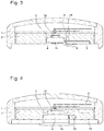
- FIGS. 2 to 4 represent cross-sectional views of several variants of a watch according to the invention.
- FIG. 1 An electronic movement or an electronic module of a watch is represented in FIG. 1 which shows a plate 2 in which is arranged a recess 5 , of cylindrical shape, housing a button cell battery 4 intended to power an electronic module 3 , conventionally a printed circuit board.
- a notch 14 facilitates the removal of the battery from its housing.
- An electrical conductor 6 taking the form of a flat flexible cable is intended to electrically connect electronic module 3 to a pole of battery 4 .
- a first end 6 a of conductor 6 is connected to electronic module 3 , typically using a connector or a solder.
- a second end 6 b of conductor 6 has a visible conductive surface that comes into contact with a wall 4 a of battery 4 . The connection to the second pole of battery 4 is not represented.
- a clamping device taking the form of a magnet 10 is positioned on connector end 6 b , opposite wall 4 a of battery 4 which is made of a ferromagnetic material. The magnetizing force between magnet 10 and wall 4 a allows end 6 b of connector 6 to be pressed and held against wall 4 a of battery 4 .
- FIG. 2 shows a schematic cross-sectional view of a watch according to the invention in which only details useful for understanding the invention appear.
- This watch includes a case 1 whose middle part 1 a and crystal 1 b are represented, in addition to a movement located inside case 1 .
- An electronic module 3 is mounted on a plate 2 . The latter is powered by a button cell battery 4 located inside a recess 5 in the plate. Electrical conductors 6 , 7 connect the two terminals of battery 4 to electronic module 3 .
- battery 4 is held in place inside recess 5 by means of an O-ring joint 8 , placed in a groove arranged in the wall of recess 5 . It is evident that any other fixing means could be used for holding the battery, such as, for example, deformable elastic means.
- one end 6 b of a conductor 6 is clamped between a magnet 10 and battery 4 .
- End 6 b has a visible conductive path, preferably, gold-plated, which is held in contact with battery 4 by the pressure exerted by magnet 10 .
- the conductor is a flat flexible FFC cable but could also be a wire or a metal clamp.
- magnet 10 may be fixed to end 6 b by any means, such as soldering or adhesive bonding.
- one end 7 b of an electrical conductor 7 is fixed to a magnet 9 which is in turn fixed by magnetic force to one side of battery 4 .
- magnet 9 is made of a conductive material or is coated with a conductive surface such as a gold plating to transmit the electrical current from battery 4 to conductor 7 .
- the fixing of the conductor to the magnet is achieved by soldering, preferably by a robotic “pick and place” soldering means.
- conductor 7 or only end 7 b thereof is formed by a metal clamp, magnet 9 may also be crimped onto the clamp.
- the other end 7 a of conductor 7 is connected to an electronic module 3 by a solder or any other assembly means allowing transmission of an electric current.
- FIG. 3 shows other variant embodiments of the invention.
- magnet 11 is a magnetic strip whose length is at least five times its thickness.
- the magnetic strip is a flexible strip.
- the reduction in magnetizing pressure on a magnetic strip of small thickness can be offset by the increase in the magnetized surface area so much so that the total contact force can be equivalent to that of a conventional magnet.
- This type of magnet has the advantage of being able to be gradually peeled off with a greatly reduced traction force compared to a rigid magnet having the same magnetizing force. This thus limits the risk of conductor 6 being pulled off when the magnet is detached. Due to its small thickness, the use of a magnetic strip 11 also allows the invention to be implemented in ultra-thin watches.
- a magnet 12 is fixed to the plate 2 by any suitable means.
- the magnet could be integral with another fixed part of the watch, such as the case middle.
- a conductor 6 electrically connects battery 4 to module 3 in one of the configurations described above.
- the clamping device in addition to ensuring an electrical connection between battery 4 and electronic module 3 , holds button cell battery 4 in place inside recess 5 in plate 2 .
- the magnetizing force is sufficient to ensure the fixing of the battery without requiring the use of other retaining means.
- Battery 4 can be detached from magnet 12 by applying pressure on the periphery of battery 4 to tilt it or by inserting a suitable tool into notch 14 . The insertion and removal of battery 4 in the watch is thereby facilitated.
- a magnet 13 is positioned facing the lateral side of a battery 4 which is electrically connected to the side of the battery opposite to that facing magnet 12 .
- the positioning of battery 4 in the plane parallel to the movement can be obtained by a magnet forming a diehedral or by two magnets having non-parallel faces.
- the watch case also includes a back cover 15 comprising a battery hatch 16 . Battery 4 is set in position once hatch 16 has been removed, simply by placing battery 4 inside recess 5 . The final positioning of battery 4 and the electrical connections are obtained automatically through the action of magnets 12 and 13 without the need to handle any element inside the watch. This configuration makes it possible to simplify the insertion and connection of the battery, and to remove the risk of damage to the movement or the conductors encountered once the watch is opened.
- button cell battery 4 was positioned parallel to the movement. It could also be positioned in another orientation, for example perpendicularly to the movement.
- a first clamp could be made on the bottom of the battery using a magnet and a second electrical clamp on the lateral side of the battery using an elastically deformed metal strip.
- the magnetic clamping device of the invention makes it possible to achieve a permanent electrical contact and to eliminate the risk of poor contact caused by the relaxation over time of elastic stresses in prior art clamps or by any plastic deformation following mishandling of the clamps during replacement of the battery. It simplifies and safeguards operations to replace the battery in the watch through easy handling of the magnetized contacts or by removing manual operations to connect the battery.
- the button cell batteries are cylindrical in shape, of variable thickness and diameter. Since the clamping of the conductor onto the battery is achieved by a magnetizing force on a surface of the battery, it is not dependent on the battery dimensions as is the case for a mechanical clamp where a reaction force is applied on the side opposite to that which receives the action of the clamp.
- the magnetic clamping device of the invention thus makes it possible to use batteries of different diameter and thickness.
- the configuration with a fixed magnet capable of holding the battery is particularly suitable for using batteries of different sizes.
- the same clamping device comprising a conductor and a magnet can be used in different watches intended to receive batteries of different size. This makes it possible to spare the use of specific expensive tools during the development of a new watch, by reusing existing clamps.
- the conductors used in the invention are flexible and electrically insulated, unlike prior art clamps.
- the result is a simplification in the design of movements and the arrangement of two conductors with respect to one another.
- the conductors may, for example, easily be connected at two close points on the same side of the electronic module and run close to each other as is the case in FIG. 3 , without the need to provide additional insulators. It is also easier to position the battery in a remote and independent manner with respect to the position of the electronic module and to place it at any point in the watch.
Landscapes
- Physics & Mathematics (AREA)
- General Physics & Mathematics (AREA)
- Engineering & Computer Science (AREA)
- Power Engineering (AREA)
- Electromagnetism (AREA)
- Chemical & Material Sciences (AREA)
- Chemical Kinetics & Catalysis (AREA)
- Electrochemistry (AREA)
- General Chemical & Material Sciences (AREA)
- Electromechanical Clocks (AREA)
- Electric Clocks (AREA)
- Battery Mounting, Suspending (AREA)
Applications Claiming Priority (3)
| Application Number | Priority Date | Filing Date | Title |
|---|---|---|---|
| EP16193192 | 2016-10-11 | ||
| EP16193192.8A EP3309628B1 (fr) | 2016-10-11 | 2016-10-11 | Montre comportant un dispositif de bridage magnétique |
| EP16193192.8 | 2016-10-11 |
Publications (2)
| Publication Number | Publication Date |
|---|---|
| US20180101141A1 US20180101141A1 (en) | 2018-04-12 |
| US10691077B2 true US10691077B2 (en) | 2020-06-23 |
Family
ID=57123887
Family Applications (1)
| Application Number | Title | Priority Date | Filing Date |
|---|---|---|---|
| US15/725,761 Active 2038-01-06 US10691077B2 (en) | 2016-10-11 | 2017-10-05 | Watch comprising a magnetic clamping device |
Country Status (4)
| Country | Link |
|---|---|
| US (1) | US10691077B2 (fr) |
| EP (1) | EP3309628B1 (fr) |
| JP (1) | JP6437071B2 (fr) |
| CN (1) | CN107942641B (fr) |
Cited By (3)
| Publication number | Priority date | Publication date | Assignee | Title |
|---|---|---|---|---|
| US11142087B1 (en) | 2021-05-10 | 2021-10-12 | Mark Ellery Ogram | Electric vehicle recharging |
| US12064791B2 (en) | 2013-03-11 | 2024-08-20 | Apple Inc. | Portable electronic device using a tactile vibrator |
| US12335422B2 (en) | 2022-01-10 | 2025-06-17 | Apple Inc. | Handheld electronic device |
Families Citing this family (2)
| Publication number | Priority date | Publication date | Assignee | Title |
|---|---|---|---|---|
| US11334164B2 (en) * | 2019-07-22 | 2022-05-17 | Apple Inc. | Portable electronic device having a haptic device with a moving battery element |
| US12594031B2 (en) * | 2022-06-03 | 2026-04-07 | Oura Health Oy | Detachable battery in a wearable ring device |
Citations (18)
| Publication number | Priority date | Publication date | Assignee | Title |
|---|---|---|---|---|
| US4763308A (en) * | 1985-06-25 | 1988-08-09 | Eta Sa Fabriques D'ebauches | Battery housing for an electronic watch |
| US4784926A (en) * | 1987-02-26 | 1988-11-15 | Kabushiki Kaisha Toshiba | Construction of battery compartment |
| US5203709A (en) * | 1992-05-18 | 1993-04-20 | Huang Ming Chuan | Device for coupling a battery to an electric appliance |
| US5569549A (en) * | 1995-03-17 | 1996-10-29 | Tv Interactive Data Corporation | Method and structure for attaching a battery to an electrical device |
| US5931693A (en) * | 1994-12-28 | 1999-08-03 | Matsushita Electric Industrial Co., Ltd. | Structure of terminal for coin-shaped battery |
| US5993248A (en) * | 1997-11-20 | 1999-11-30 | Itt Manufacturing Enterprises, Inc. | Battery connector |
| JP2000030810A (ja) | 1998-07-07 | 2000-01-28 | Seiko Instruments Inc | 電源接続装置及び該電源接続装置を有する電子機器 |
| US6186353B1 (en) * | 1998-04-21 | 2001-02-13 | Elizabeth P. Crocker | Battery cover connector |
| JP3188425B2 (ja) * | 1999-03-08 | 2001-07-16 | 株式会社マルナカ製作所 | セット動噴 |
| US20020064098A1 (en) * | 2000-11-29 | 2002-05-30 | Roger Marquis | Timepiece comprising means for allowing electric access to electric or electronic components of this timepiece |
| US20080002528A1 (en) * | 2006-05-22 | 2008-01-03 | Nike, Inc. | Watch Display Using Light Sources With A Translucent Cover |
| CN201233941Y (zh) * | 2008-06-24 | 2009-05-06 | 北京嘉捷源技术开发有限公司 | 磁性软连接端口电池充电器 |
| US20120051193A1 (en) | 2010-09-01 | 2012-03-01 | Hon Hai Precision Industry Co., Ltd. | Wearable electronic device |
| US20120206088A1 (en) | 2011-02-10 | 2012-08-16 | Samsung Sdi Co., Ltd. | Battery pack and charging system including battery pack |
| JP3188425U (ja) * | 2013-10-24 | 2014-01-23 | 株式会社メイルリバー | ボタン電池ホルダー |
| US20140273546A1 (en) * | 2013-03-15 | 2014-09-18 | Motorola Mobility Llc | Magnetic Electrical Connection System for an Electronic Device |
| US20160329001A1 (en) * | 2014-01-16 | 2016-11-10 | Mariella Labels Oy | Fastening arrangement for a replacable voltage source for an electronic price label |
| US20180004472A1 (en) * | 2015-01-19 | 2018-01-04 | Mariella Labels Oy | Electronic price label and a battery unit for an electronic price label |
Family Cites Families (7)
| Publication number | Priority date | Publication date | Assignee | Title |
|---|---|---|---|---|
| CH392669A4 (fr) | 1969-03-17 | 1971-02-26 | ||
| JPS51158329U (fr) * | 1975-06-11 | 1976-12-16 | ||
| FR2460499B2 (fr) | 1979-07-04 | 1986-04-11 | Ebauches Sa | |
| JPH10334881A (ja) * | 1997-05-28 | 1998-12-18 | Saitama Nippon Denki Kk | 電源端子及びそれに接触する外部端子 |
| JPH1151028A (ja) * | 1997-08-02 | 1999-02-23 | Nakajima Kogyo:Kk | 照明付ホイールナット |
| JP2008277096A (ja) * | 2007-04-27 | 2008-11-13 | Japan Radio Co Ltd | 携帯型通信装置 |
| CN103631134A (zh) * | 2013-11-14 | 2014-03-12 | 合肥华恒电子科技有限责任公司 | 一种具有可分离结构的智能手表 |
-
2016
- 2016-10-11 EP EP16193192.8A patent/EP3309628B1/fr active Active
-
2017
- 2017-09-26 JP JP2017184571A patent/JP6437071B2/ja active Active
- 2017-10-05 US US15/725,761 patent/US10691077B2/en active Active
- 2017-10-10 CN CN201710933973.4A patent/CN107942641B/zh active Active
Patent Citations (19)
| Publication number | Priority date | Publication date | Assignee | Title |
|---|---|---|---|---|
| US4763308A (en) * | 1985-06-25 | 1988-08-09 | Eta Sa Fabriques D'ebauches | Battery housing for an electronic watch |
| US4784926A (en) * | 1987-02-26 | 1988-11-15 | Kabushiki Kaisha Toshiba | Construction of battery compartment |
| US5203709A (en) * | 1992-05-18 | 1993-04-20 | Huang Ming Chuan | Device for coupling a battery to an electric appliance |
| US5931693A (en) * | 1994-12-28 | 1999-08-03 | Matsushita Electric Industrial Co., Ltd. | Structure of terminal for coin-shaped battery |
| US5569549A (en) * | 1995-03-17 | 1996-10-29 | Tv Interactive Data Corporation | Method and structure for attaching a battery to an electrical device |
| US5993248A (en) * | 1997-11-20 | 1999-11-30 | Itt Manufacturing Enterprises, Inc. | Battery connector |
| US6186353B1 (en) * | 1998-04-21 | 2001-02-13 | Elizabeth P. Crocker | Battery cover connector |
| US6217339B1 (en) | 1998-07-07 | 2001-04-17 | Seiko Instruments Inc. | Power source connecting apparatus and electronic appliance having the same power source connecting apparatus |
| JP2000030810A (ja) | 1998-07-07 | 2000-01-28 | Seiko Instruments Inc | 電源接続装置及び該電源接続装置を有する電子機器 |
| JP3188425B2 (ja) * | 1999-03-08 | 2001-07-16 | 株式会社マルナカ製作所 | セット動噴 |
| US20020064098A1 (en) * | 2000-11-29 | 2002-05-30 | Roger Marquis | Timepiece comprising means for allowing electric access to electric or electronic components of this timepiece |
| US20080002528A1 (en) * | 2006-05-22 | 2008-01-03 | Nike, Inc. | Watch Display Using Light Sources With A Translucent Cover |
| CN201233941Y (zh) * | 2008-06-24 | 2009-05-06 | 北京嘉捷源技术开发有限公司 | 磁性软连接端口电池充电器 |
| US20120051193A1 (en) | 2010-09-01 | 2012-03-01 | Hon Hai Precision Industry Co., Ltd. | Wearable electronic device |
| US20120206088A1 (en) | 2011-02-10 | 2012-08-16 | Samsung Sdi Co., Ltd. | Battery pack and charging system including battery pack |
| US20140273546A1 (en) * | 2013-03-15 | 2014-09-18 | Motorola Mobility Llc | Magnetic Electrical Connection System for an Electronic Device |
| JP3188425U (ja) * | 2013-10-24 | 2014-01-23 | 株式会社メイルリバー | ボタン電池ホルダー |
| US20160329001A1 (en) * | 2014-01-16 | 2016-11-10 | Mariella Labels Oy | Fastening arrangement for a replacable voltage source for an electronic price label |
| US20180004472A1 (en) * | 2015-01-19 | 2018-01-04 | Mariella Labels Oy | Electronic price label and a battery unit for an electronic price label |
Non-Patent Citations (3)
| Title |
|---|
| European Search Report dated Mar. 13, 2017 in European Application 16193192.8, filed on Oct. 11, 2016 (with English Translation of Categories of cited documents). |
| Matsuyama, S, English Translation of JP 3188425 U, originally published on Jan. 23, 2014, full document (Year: 2014). * |
| Paper battery holder with magnets, Sep. 6, 2015, Chibitronics, retrieved from https://chibitronics.com/paper-battery-holder-with-magnets/ on Mar. 4, 2019, full document (Year: 2015). * |
Cited By (3)
| Publication number | Priority date | Publication date | Assignee | Title |
|---|---|---|---|---|
| US12064791B2 (en) | 2013-03-11 | 2024-08-20 | Apple Inc. | Portable electronic device using a tactile vibrator |
| US11142087B1 (en) | 2021-05-10 | 2021-10-12 | Mark Ellery Ogram | Electric vehicle recharging |
| US12335422B2 (en) | 2022-01-10 | 2025-06-17 | Apple Inc. | Handheld electronic device |
Also Published As
| Publication number | Publication date |
|---|---|
| JP2018063244A (ja) | 2018-04-19 |
| EP3309628B1 (fr) | 2020-02-05 |
| HK1252474A1 (zh) | 2019-05-24 |
| US20180101141A1 (en) | 2018-04-12 |
| EP3309628A1 (fr) | 2018-04-18 |
| CN107942641A (zh) | 2018-04-20 |
| JP6437071B2 (ja) | 2018-12-12 |
| CN107942641B (zh) | 2021-06-08 |
Similar Documents
| Publication | Publication Date | Title |
|---|---|---|
| US10691077B2 (en) | Watch comprising a magnetic clamping device | |
| US20190033690A1 (en) | Heating device for camera module and camera module having same | |
| JP2011119462A (ja) | 太陽電池モジュール用端子ボックス | |
| CN102788333A (zh) | Led基板用电连接装置 | |
| KR100736399B1 (ko) | 마그네트를 이용한 비삽입 접촉식 인터페이스 | |
| KR20100064995A (ko) | 커넥터 결합장치 | |
| US10079455B2 (en) | Smart switching charger and power connection device thereof | |
| HK1252474B (zh) | 包括磁性夹持装置的手表 | |
| JP2011192426A (ja) | 電池収納部の構造 | |
| US8808022B2 (en) | Connector structure | |
| US11316286B2 (en) | Electrical connector | |
| JP3656032B2 (ja) | バッテリーコネクタ | |
| US11063375B2 (en) | Connection instrument | |
| CN112086778A (zh) | 连接器、对象连接器以及连接装置 | |
| JP6198018B2 (ja) | 磁気接合式コネクタ | |
| CN106352308B (zh) | Led电连接器以及led灯 | |
| KR200382247Y1 (ko) | 마그네트를 이용한 비삽입 접촉식 커넥터와 이 커넥터가연결되는 이동통신 단말기 및 휴대폰용 충전기 | |
| JP5112410B2 (ja) | 半田付け構造 | |
| CN213401720U (zh) | 一种可固定于手机边缘的电接头 | |
| CN102035034B (zh) | 一种方形锂离子电池组 | |
| JPH0568070U (ja) | 電池の接点構造 | |
| CH713022A2 (fr) | Montre comportant un dispositif de bridage magnétique pour pile. | |
| CN211507746U (zh) | 一种电池组件和一种电池盒组件 | |
| JP2006302527A (ja) | 電池ホルダ | |
| JPS6193565A (ja) | コネクタ |
Legal Events
| Date | Code | Title | Description |
|---|---|---|---|
| AS | Assignment |
Owner name: ETA SA MANUFACTURE HORLOGERE SUISSE, SWITZERLAND Free format text: ASSIGNMENT OF ASSIGNORS INTEREST;ASSIGNOR:LAGORGETTE, PASCAL;REEL/FRAME:043797/0906 Effective date: 20170901 |
|
| FEPP | Fee payment procedure |
Free format text: ENTITY STATUS SET TO UNDISCOUNTED (ORIGINAL EVENT CODE: BIG.); ENTITY STATUS OF PATENT OWNER: LARGE ENTITY |
|
| STPP | Information on status: patent application and granting procedure in general |
Free format text: NON FINAL ACTION MAILED |
|
| STPP | Information on status: patent application and granting procedure in general |
Free format text: RESPONSE TO NON-FINAL OFFICE ACTION ENTERED AND FORWARDED TO EXAMINER |
|
| STPP | Information on status: patent application and granting procedure in general |
Free format text: FINAL REJECTION MAILED |
|
| STPP | Information on status: patent application and granting procedure in general |
Free format text: DOCKETED NEW CASE - READY FOR EXAMINATION |
|
| STPP | Information on status: patent application and granting procedure in general |
Free format text: NOTICE OF ALLOWANCE MAILED -- APPLICATION RECEIVED IN OFFICE OF PUBLICATIONS |
|
| STPP | Information on status: patent application and granting procedure in general |
Free format text: PUBLICATIONS -- ISSUE FEE PAYMENT VERIFIED |
|
| STCF | Information on status: patent grant |
Free format text: PATENTED CASE |
|
| MAFP | Maintenance fee payment |
Free format text: PAYMENT OF MAINTENANCE FEE, 4TH YEAR, LARGE ENTITY (ORIGINAL EVENT CODE: M1551); ENTITY STATUS OF PATENT OWNER: LARGE ENTITY Year of fee payment: 4 |