US10690516B2 - Protective compound-enveloped sensor for detecting the position of an encoder element - Google Patents
Protective compound-enveloped sensor for detecting the position of an encoder element Download PDFInfo
- Publication number
- US10690516B2 US10690516B2 US14/653,957 US201314653957A US10690516B2 US 10690516 B2 US10690516 B2 US 10690516B2 US 201314653957 A US201314653957 A US 201314653957A US 10690516 B2 US10690516 B2 US 10690516B2
- Authority
- US
- United States
- Prior art keywords
- sensor
- transducer
- magnetic core
- protective compound
- wiring carrier
- Prior art date
- Legal status (The legal status is an assumption and is not a legal conclusion. Google has not performed a legal analysis and makes no representation as to the accuracy of the status listed.)
- Expired - Fee Related, expires
Links
- 230000001681 protective effect Effects 0.000 title claims abstract description 39
- 150000001875 compounds Chemical class 0.000 claims abstract description 34
- 238000004804 winding Methods 0.000 claims description 14
- 239000000463 material Substances 0.000 claims description 6
- 229920001187 thermosetting polymer Polymers 0.000 claims description 6
- 230000001939 inductive effect Effects 0.000 claims description 4
- 238000005259 measurement Methods 0.000 abstract description 12
- 230000001419 dependent effect Effects 0.000 abstract description 7
- 238000011161 development Methods 0.000 description 11
- 238000004519 manufacturing process Methods 0.000 description 11
- 230000005540 biological transmission Effects 0.000 description 9
- 238000001746 injection moulding Methods 0.000 description 7
- JQUCWIWWWKZNCS-LESHARBVSA-N C(C1=CC=CC=C1)(=O)NC=1SC[C@H]2[C@@](N1)(CO[C@H](C2)C)C=2SC=C(N2)NC(=O)C2=NC=C(C=C2)OC(F)F Chemical compound C(C1=CC=CC=C1)(=O)NC=1SC[C@H]2[C@@](N1)(CO[C@H](C2)C)C=2SC=C(N2)NC(=O)C2=NC=C(C=C2)OC(F)F JQUCWIWWWKZNCS-LESHARBVSA-N 0.000 description 5
- 238000004382 potting Methods 0.000 description 5
- XEEYBQQBJWHFJM-UHFFFAOYSA-N Iron Chemical compound [Fe] XEEYBQQBJWHFJM-UHFFFAOYSA-N 0.000 description 4
- 238000012545 processing Methods 0.000 description 4
- 238000011109 contamination Methods 0.000 description 3
- 239000004952 Polyamide Substances 0.000 description 2
- 238000004026 adhesive bonding Methods 0.000 description 2
- 230000000694 effects Effects 0.000 description 2
- 230000004907 flux Effects 0.000 description 2
- 238000009434 installation Methods 0.000 description 2
- 229910052742 iron Inorganic materials 0.000 description 2
- 238000000034 method Methods 0.000 description 2
- 229920002647 polyamide Polymers 0.000 description 2
- 238000005476 soldering Methods 0.000 description 2
- 230000009466 transformation Effects 0.000 description 2
- 230000004913 activation Effects 0.000 description 1
- 239000003570 air Substances 0.000 description 1
- 239000012080 ambient air Substances 0.000 description 1
- 238000013459 approach Methods 0.000 description 1
- 238000006243 chemical reaction Methods 0.000 description 1
- 239000004020 conductor Substances 0.000 description 1
- 230000006378 damage Effects 0.000 description 1
- 238000013461 design Methods 0.000 description 1
- 238000001514 detection method Methods 0.000 description 1
- 239000013013 elastic material Substances 0.000 description 1
- 230000005672 electromagnetic field Effects 0.000 description 1
- 238000005538 encapsulation Methods 0.000 description 1
- 238000005516 engineering process Methods 0.000 description 1
- 230000007613 environmental effect Effects 0.000 description 1
- 239000012530 fluid Substances 0.000 description 1
- 238000005070 sampling Methods 0.000 description 1
- 238000007789 sealing Methods 0.000 description 1
- 238000005245 sintering Methods 0.000 description 1
- 239000000126 substance Substances 0.000 description 1
- 239000000758 substrate Substances 0.000 description 1
Images



Classifications
-
- G—PHYSICS
- G01—MEASURING; TESTING
- G01D—MEASURING NOT SPECIALLY ADAPTED FOR A SPECIFIC VARIABLE; ARRANGEMENTS FOR MEASURING TWO OR MORE VARIABLES NOT COVERED IN A SINGLE OTHER SUBCLASS; TARIFF METERING APPARATUS; MEASURING OR TESTING NOT OTHERWISE PROVIDED FOR
- G01D5/00—Mechanical means for transferring the output of a sensing member; Means for converting the output of a sensing member to another variable where the form or nature of the sensing member does not constrain the means for converting; Transducers not specially adapted for a specific variable
- G01D5/12—Mechanical means for transferring the output of a sensing member; Means for converting the output of a sensing member to another variable where the form or nature of the sensing member does not constrain the means for converting; Transducers not specially adapted for a specific variable using electric or magnetic means
- G01D5/14—Mechanical means for transferring the output of a sensing member; Means for converting the output of a sensing member to another variable where the form or nature of the sensing member does not constrain the means for converting; Transducers not specially adapted for a specific variable using electric or magnetic means influencing the magnitude of a current or voltage
- G01D5/20—Mechanical means for transferring the output of a sensing member; Means for converting the output of a sensing member to another variable where the form or nature of the sensing member does not constrain the means for converting; Transducers not specially adapted for a specific variable using electric or magnetic means influencing the magnitude of a current or voltage by varying inductance, e.g. by a movable armature
-
- G—PHYSICS
- G01—MEASURING; TESTING
- G01D—MEASURING NOT SPECIALLY ADAPTED FOR A SPECIFIC VARIABLE; ARRANGEMENTS FOR MEASURING TWO OR MORE VARIABLES NOT COVERED IN A SINGLE OTHER SUBCLASS; TARIFF METERING APPARATUS; MEASURING OR TESTING NOT OTHERWISE PROVIDED FOR
- G01D5/00—Mechanical means for transferring the output of a sensing member; Means for converting the output of a sensing member to another variable where the form or nature of the sensing member does not constrain the means for converting; Transducers not specially adapted for a specific variable
- G01D5/12—Mechanical means for transferring the output of a sensing member; Means for converting the output of a sensing member to another variable where the form or nature of the sensing member does not constrain the means for converting; Transducers not specially adapted for a specific variable using electric or magnetic means
- G01D5/14—Mechanical means for transferring the output of a sensing member; Means for converting the output of a sensing member to another variable where the form or nature of the sensing member does not constrain the means for converting; Transducers not specially adapted for a specific variable using electric or magnetic means influencing the magnitude of a current or voltage
- G01D5/20—Mechanical means for transferring the output of a sensing member; Means for converting the output of a sensing member to another variable where the form or nature of the sensing member does not constrain the means for converting; Transducers not specially adapted for a specific variable using electric or magnetic means influencing the magnitude of a current or voltage by varying inductance, e.g. by a movable armature
- G01D5/2006—Mechanical means for transferring the output of a sensing member; Means for converting the output of a sensing member to another variable where the form or nature of the sensing member does not constrain the means for converting; Transducers not specially adapted for a specific variable using electric or magnetic means influencing the magnitude of a current or voltage by varying inductance, e.g. by a movable armature by influencing the self-induction of one or more coils
- G01D5/2013—Mechanical means for transferring the output of a sensing member; Means for converting the output of a sensing member to another variable where the form or nature of the sensing member does not constrain the means for converting; Transducers not specially adapted for a specific variable using electric or magnetic means influencing the magnitude of a current or voltage by varying inductance, e.g. by a movable armature by influencing the self-induction of one or more coils by a movable ferromagnetic element, e.g. a core
-
- G—PHYSICS
- G01—MEASURING; TESTING
- G01B—MEASURING LENGTH, THICKNESS OR SIMILAR LINEAR DIMENSIONS; MEASURING ANGLES; MEASURING AREAS; MEASURING IRREGULARITIES OF SURFACES OR CONTOURS
- G01B7/00—Measuring arrangements characterised by the use of electric or magnetic techniques
- G01B7/14—Measuring arrangements characterised by the use of electric or magnetic techniques for measuring distance or clearance between spaced objects or spaced apertures
-
- G—PHYSICS
- G01—MEASURING; TESTING
- G01D—MEASURING NOT SPECIALLY ADAPTED FOR A SPECIFIC VARIABLE; ARRANGEMENTS FOR MEASURING TWO OR MORE VARIABLES NOT COVERED IN A SINGLE OTHER SUBCLASS; TARIFF METERING APPARATUS; MEASURING OR TESTING NOT OTHERWISE PROVIDED FOR
- G01D11/00—Component parts of measuring arrangements not specially adapted for a specific variable
- G01D11/24—Housings ; Casings for instruments
- G01D11/245—Housings for sensors
-
- Y—GENERAL TAGGING OF NEW TECHNOLOGICAL DEVELOPMENTS; GENERAL TAGGING OF CROSS-SECTIONAL TECHNOLOGIES SPANNING OVER SEVERAL SECTIONS OF THE IPC; TECHNICAL SUBJECTS COVERED BY FORMER USPC CROSS-REFERENCE ART COLLECTIONS [XRACs] AND DIGESTS
- Y10—TECHNICAL SUBJECTS COVERED BY FORMER USPC
- Y10T—TECHNICAL SUBJECTS COVERED BY FORMER US CLASSIFICATION
- Y10T29/00—Metal working
- Y10T29/49—Method of mechanical manufacture
- Y10T29/49002—Electrical device making
- Y10T29/49117—Conductor or circuit manufacturing
- Y10T29/49124—On flat or curved insulated base, e.g., printed circuit, etc.
- Y10T29/4913—Assembling to base an electrical component, e.g., capacitor, etc.
Definitions
- the invention relates to a sensor for detecting a position of an encoder element, to a method for producing the sensor and to a method for producing a transformer.
- WO 2010/037 810 A1 discloses a sensor for outputting an electrical signal on the basis of a detected physical variable.
- the sensor has a measuring circuit which is enclosed in a circuit housing.
- An aspect of the invention consists in improving the known sensor.
- a sensor for detecting a position of an encoder element which outputs a physical variable which is dependent on the position, comprises a transducer for converting the physical variable into an electrical encoder signal, a circuit on a wiring carrier for receiving the encoder signal from the transducer and outputting a measurement signal corresponding to the encoder signal, and a protective compound, which at least partially envelops the transducer and the wiring carrier and thus holds the transducer on the wiring carrier.
- the specified sensor is based on the consideration that the measuring circuit in the sensor mentioned at the outset could be desired to detect a physical variable which is dependent on the position of an encoder element, such as an electrical and/or magnetic field, light or sound and to convert this signal into an electrical measurement signal which is dependent on the position of the encoder element.
- an encoder element such as an electrical and/or magnetic field, light or sound
- Such a position sensor could detect, for example, angular positions and/or linear positions of the encoder element and thus determine the position of a gas pedal and/or brake pedal in a vehicle, for example.
- a transducer for converting the physical variable which is output by the encoder and which is dependent on the position to be detected into an encoder signal, which is dependent at least on the desired measurement signal needs to be held fixedly on a wiring carrier on which the circuit which outputs the measurement signal is also borne.
- the transducer could be accommodated in a transducer housing.
- the transducer accommodated in the transducer housing could ultimately be arranged and potted together with the other component parts in a sensor housing.
- the specified sensor is based on the concept that all of the component parts could be held together via a common protective compound. All of the electrical component parts of the specified sensor such as the transducer and the circuit could be brought into contact with one another, for example, using adhesive-bonding, soldering or sintering technology.
- the component parts with which electrical contact has been made could now be encapsulated by injection molding or potting using the protective compound directly in a single injection-molding operation, which in this way not only holds together the component parts of the sensor but also houses them and thus protects them from contamination and other environmental influences such as moisture. In this way, the specified sensor can be constructed at low cost and in a manner which saves on installation space.
- the transducer and the wiring carrier can be encapsulated by injection molding or potting using the protective compound directly.
- the transducer and the wiring carrier can be correspondingly encapsulated by injection molding or potting using the protective compound in a single injection-molding operation or a single potting operation.
- the protective compound can form directly an outer housing of the specified sensor.
- the protective compound has a coefficient of expansion which is within the range of a coefficient of expansion of the electromechanical components.
- the specified development is based on the consideration that a different coefficient of expansion between the transducer and the protective compound could result in an input of mechanical loads such as mechanical stresses. These mechanical loads could falsify the measurement result, for which reason, within the scope of the specified sensor, the stresses which are input should be kept as low as possible. This is achieved within the scope of the development by a suitable selection of the coefficient of expansion of the protective compound and the transducer.
- the protective compound comprises a thermosetting plastic material.
- the thermosetting plastic material has a particularly advantageous effect within the scope of the specified sensor if an electrical component which converts a magnetic flux and has a magnetic core is used as the transducer, the conversion principle of said electrical component being dependent on saturation of the magnetic core. The saturation of the magnetic core is achieved depending on the stresses that are input, which can thus falsify the measurement result.
- Conventional materials for the magnetic core such as iron, have a coefficient of expansion which is within the range of the coefficients of expansion of thermosetting plastic materials, however.
- the circuit on the wiring carrier comprises a part which is free of the protective compound.
- the sensor could be held fixedly on this free part if the wiring carrier and the transducer are enveloped by the protective compound.
- the circuit in the part which is free from the protective compound is designed to output the measurement signal.
- that part which is exposed and is necessary for applying the protective compound around the wiring carrier and the transducer can be used usefully to connect the specified sensor to a superordinate unit such as, for example, a motor controller in a vehicle via a cable, for example.
- Electrical contact can be made between the cable and the circuit in the exposed part in this case via contact-making springs, press-in pins, edge grip connectors, soldering or adhesive bonding.
- the transducer is an electrical transformer, in particular a linear inductive position sensor (LIPS), which is designed to transmit at least one reference signal depending on a position of the encoder element as encoder signal.
- the transformer may be the abovementioned electrical component which converts the magnetic flux.
- a transformer should be understood to mean an electrical component which has two coils which are galvanically isolated from one another and which transmit electrical energy between one another via a common contact medium such as air or the abovementioned magnetic core. If the encoder element is a magnet itself, for example, it changes the transmission properties of the common contact medium, which is demonstrated in a changed transmission behavior of the two coils.
- An LIPS within the scope of the specified sensor is intended to be a transformer which has a third coil, wherein the second and third coils are arranged for the interchange of electrical energy with the first coil.
- a specific configuration of the transformation ratios between the first and second coils and the first and third coils results. Since the position of the encoder element is now detected at two different locations using two different transformation ratios, the abovementioned saturation of the magnetic core can also be used in the detection of the position.
- the magnetic core in a preferred development has a coefficient of expansion which is in the range of a coefficient of expansion of the coil former.
- the coil former can be applied directly to the magnetic core, for example by encapsulation by injection molding with a thermosetting plastic without any inputs of mechanical stresses on the mechanical core and therefore falsifications of the measurement result by the transformer occurring.
- a method for producing a specified sensor comprises the following steps:
- a surface of the wiring carrier and/or of the transducer which is to be enveloped by the protective compound is activated prior to the transducer and the wiring carrier being enveloped by the protective compound.
- Activation of the surface of the wiring carrier and/or of the converter will be understood below to mean partial destruction of the molecular structure of the surface of the wiring carrier and/or the converter so that free radicals are produced on the surface of the wiring carrier and/or the converter.
- These free radicals are capable of entering into chemical and/or physical bonds with the protective compound so that said protective compound can no longer be detached from the surface of the wiring carrier and/or the converter.
- the protective compound can in this case comprise a polar material, such as polyamide.
- the polar polyamide can be connected physically to the activated surface of the wiring carrier and/or the converter in a manner known to a person skilled in the art and can thus improve the mechanical hold between the wiring carrier and the converter.
- At least part of the surface of the wiring carrier and/or the converter is roughened in the contact region with the protective compound so that the effective activated surface is enlarged and the adhering effect between the wiring carrier and/or the converter and the protective compound is increased.
- the roughened part of the surface of the wiring carrier and/or the converter is roughened using a laser.
- the surface of the wiring carrier and/or the converter can not only be activated by the laser, but also form-releasing means which may be provided are also removed by the laser from the surface of the wiring carrier and/or the converter, which form-releasing means could suppress adhesion between the wiring carrier and/or the converter and the protective compound.
- a method for producing an electrical transformer comprises the following steps:
- the specified method can be extended by features which correspond to the features of the abovementioned transformer accordingly.
- a coefficient of expansion of the magnetic core can be in the range of a coefficient of expansion of the coil former with the advantages already mentioned.
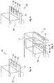
- FIG. 1 shows a tandem master cylinder comprising a position sensor
- FIG. 2 shows the position sensor from FIG. 1 ,
- FIG. 3 shows an interface at the position sensor shown in FIG. 2 .
- FIG. 4 shows an alternative interface at the position sensor shown in FIG. 2 .
- FIG. 5 shows another alternative interface at the position sensor shown in FIG. 2 .
- FIG. 6 shows a converter in the position sensor shown in FIG. 2 in a first production state
- FIG. 7 shows a converter in the position sensor shown in FIG. 2 in a second production state.
- FIG. 1 shows a tandem master cylinder 2 comprising a position sensor 4 .
- the tandem master cylinder 2 also has a pressure piston 6 , which is arranged movably in a movement direction 8 in a housing 10 , wherein the movement of the pressure piston 6 can be controlled by a foot pedal (not shown).
- the pressure piston 6 itself is divided into a primary piston 12 and a secondary piston 14 , wherein the primary piston 12 closes an inlet of the housing 10 and the secondary piston 12 divides the interior of the housing 10 into a primary chamber 16 and a secondary chamber 18 .
- a secondary collar 20 is arranged in the region of the inlet of the housing 10 on the primary piston 12 , which secondary collar insulates the interior of the housing 10 from the ambient air.
- a primary collar 22 When viewed into the interior of the housing 10 , a primary collar 22 follows the secondary collar 20 , said primary collar sealing a gap between the primary piston 12 and a wall of the housing 10 .
- a pressure collar 24 on the secondary piston 14 isolates the pressure of the primary chamber 16 from the pressure of the secondary chamber 18 .
- a further primary collar 26 on the secondary piston 14 seals a gap between the secondary piston 14 and the wall of the housing 10 .
- the primary piston 12 is supported against the secondary piston 14 via a first spring 28
- the secondary piston is supported against a housing base via a second spring 30 .
- hydraulic fluid (not shown) can be supplied to the primary chamber 16 and the secondary chamber 18 via a first and second connection 32 , 34 .
- the position sensor 4 has a sampling element in the form of a slide 36 comprising a sensor magnet 37 at its top end, which, when viewed into the plane of the drawing, can be pushed beneath a sensor circuit 38 (yet to be described).
- the primary piston 12 In order to push the slide 36 , the primary piston 12 has a flange 40 , which the slide 36 abuts. The flange 40 and the primary piston 12 therefore together form a measurement object, whose position is determined by the sensor circuit 38 (yet to be described) of the position sensor 4 .
- the sensor circuit 38 is formed from a plurality of conductor tracks on a wiring carrier 42 , such as a leadframe, a printed circuit board or another substrate. In order to protect against contamination, for example, a cover 46 can be positioned on the printed circuit board 42 with the sensor circuit 38 .
- FIG. 2 shows the position sensor 4 shown in FIG. 1 .
- the circuit 38 of the position sensor comprises a transducer 48 , which in the present embodiment is in the form of a linear inductive position sensor (LIPS).
- the transducer 48 detects a magnetic field 50 of the sensor magnet 37 and thereupon outputs an electrical sensor signal (not denoted) to the circuit 38 on the basis of this magnetic field.
- This sensor signal is converted by a first signal processing chip 52 and a second signal processing chip 54 into a measurement signal (not denoted), from which the position of the slide 36 and therefore the position of the flange 40 and the primary piston 12 is provided.
- the measurement signal thus produced can finally be tapped off at a transmission interface 56 of the position sensor 4 via a cable (not illustrated) and passed on to a higher signal processing unit (not illustrated) such as, for example, a motor controller in a vehicle (not illustrated).
- the circuit 38 can comprise protection elements 58 for protecting the two signal processing chips 52 , 54 , for example from an overvoltage.
- a shielding plate 60 can be arranged between the circuit 38 and the transducer 48 , said shielding plate shielding electromagnetic fields between the circuit 38 and the transducer 48 and thus avoiding an influence of the circuit 38 on the transducer 48 .
- the transducer 48 is arranged via a form-fitting connection 62 in a defined position on the wiring carrier 42 .
- a protective compound 64 which holds the wiring carrier 42 and the transducer 48 mechanically together, the wiring carrier 42 and the transducer 48 .
- the protective compound 64 can not only ensure a mechanical stability between the wiring carrier 42 and the transducer 48 , but an interior of the position sensor 4 with the circuit 38 is also effectively protected from contamination. In this case, this interior can particularly preferably likewise be filled with the protective compound 64 .
- the position sensor 4 can be encapsulated by injection molding, for example, with the protective compound 64 during production.
- the wiring carrier 42 of the position sensor 4 can be held on the transmission interface 56 , for example, which in any case needs to remain free in order to make electrical contact with the abovementioned cable.
- This transmission interface 56 can be embodied differently, which is shown in FIGS. 3 to 5 .
- the transmission interface can comprise contact bores 66 or edge group plugs 68 .
- the transmission interface 56 can in this case also be surrounded by a wall 70 formed from the protective compound 64 , as shown in FIGS. 2 and 5 .
- FIG. 6 shows the transducer 48 in the position sensor 4 from FIG. 2 in a first production state.
- a leadframe 72 with contact legs 74 is punched out for the first production state, said leadframe mechanically supporting the transducer 48 on the abovementioned wiring carrier 42 and making electrical contact between said transducer and the circuit 38 on the wiring carrier 42 .
- the contact legs 74 have been provided with a reference symbol in FIG. 6 .
- a magnetic core 76 is arranged in the leadframe 72 , said magnetic core later being provided for transmission of a magnetic field between coils (yet to be described).
- FIG. 7 shows the transducer 48 in the position sensor 4 from FIG. 2 in a second production state.
- the leadframe 72 is enveloped with the magnetic core 76 by a transducer protective compound 78 .
- This transducer protective compound 78 in the present embodiment consists of a thermosetting plastic, which has a substantially identical coefficient of thermal expansion to the magnetic core 76 , which can be produced from iron, for example. In the event of temperature fluctuations, hardly any mechanical stresses can be input into the magnetic core 76 .
- the transducer protective compound 78 is in this case formed with four separating elements 80 such that they divide the magnetic core 76 into two outer winding regions 82 and an inner winding region 84 .
- the outer winding regions 82 are shorter than the inner winding region 84 .
- the contact legs 74 can then be bent in the direction of a lower side of the transducer 48 , as shown in FIG. 7 .
- coil wires are wound onto the transducer into the winding regions 82 , 84 .
- a primary coil is in this case wound beyond all of the winding regions 82 , 84 , whereas a physically identical secondary coil is wound on into in each case one of the outer winding regions 82 .
- an electrical AC voltage signal is applied to the primary coil, for example, which AC voltage signal should induce an identical output signal in the physically identical secondary coils via the magnetic core 76 .
- the sensor magnet 37 of the slide 36 now approaches one of the two secondary coils, it drives the magnetic core 76 into saturation. This results in a changed transmission behavior of the electrical AC voltage signal between the primary coil and the corresponding secondary coil, to which the sensor magnet 37 has got closer, which can be evaluated via the sensor circuit in a manner known to a person skilled in the art. In this way, the position of the sensor magnet 37 can be detected via the transducer 48 .
Landscapes
- Physics & Mathematics (AREA)
- General Physics & Mathematics (AREA)
- Transmission And Conversion Of Sensor Element Output (AREA)
- Measurement Of Length, Angles, Or The Like Using Electric Or Magnetic Means (AREA)
Applications Claiming Priority (4)
| Application Number | Priority Date | Filing Date | Title |
|---|---|---|---|
| DE102012224075.6 | 2012-12-20 | ||
| DE102012224075.6A DE102012224075A1 (de) | 2012-12-20 | 2012-12-20 | Sensor zum Erfassen einer Position eines Geberelements |
| DE102012224075 | 2012-12-20 | ||
| PCT/EP2013/076927 WO2014095881A1 (de) | 2012-12-20 | 2013-12-17 | Sensor zum erfassen einer position eines geberelements |
Publications (2)
| Publication Number | Publication Date |
|---|---|
| US20150316395A1 US20150316395A1 (en) | 2015-11-05 |
| US10690516B2 true US10690516B2 (en) | 2020-06-23 |
Family
ID=49779914
Family Applications (1)
| Application Number | Title | Priority Date | Filing Date |
|---|---|---|---|
| US14/653,957 Expired - Fee Related US10690516B2 (en) | 2012-12-20 | 2013-12-17 | Protective compound-enveloped sensor for detecting the position of an encoder element |
Country Status (6)
| Country | Link |
|---|---|
| US (1) | US10690516B2 (de) |
| EP (1) | EP2936077B1 (de) |
| KR (1) | KR102107267B1 (de) |
| CN (1) | CN105008866B (de) |
| DE (1) | DE102012224075A1 (de) |
| WO (1) | WO2014095881A1 (de) |
Families Citing this family (6)
| Publication number | Priority date | Publication date | Assignee | Title |
|---|---|---|---|---|
| DE102014213231A1 (de) * | 2014-07-08 | 2016-01-14 | Continental Automotive Gmbh | Sensorunterseitig verschaltete passive Bauelemente |
| DE102015207521A1 (de) | 2015-04-23 | 2016-10-27 | Continental Teves Ag & Co. Ohg | Sensoranordnung mit einem in ein Hülsenelement integriertes Sensorelement |
| DE102016209841A1 (de) * | 2016-06-03 | 2017-12-07 | Continental Teves Ag & Co. Ohg | Sensor und Sensoranordnung |
| DE102018217514A1 (de) * | 2018-10-12 | 2020-04-16 | Continental Teves Ag & Co. Ohg | Wegsensor mit Rückschlusskern |
| DE102018217517A1 (de) * | 2018-10-12 | 2020-04-16 | Continental Teves Ag & Co. Ohg | Wegsensor mit Rückschlusskern in einer Gehäusekavität |
| CN112212903B (zh) * | 2020-10-22 | 2025-09-30 | 西安热工研究院有限公司 | 一种可伸缩的传感器固定及感应装置 |
Citations (50)
| Publication number | Priority date | Publication date | Assignee | Title |
|---|---|---|---|---|
| US3371272A (en) * | 1964-09-09 | 1968-02-27 | Stanton Joshua Clarke | Electromagnetic sensing probe structure and system for gaging proximity of metals and the like utilizing a linear variable differential transformer |
| GB2037087A (en) * | 1978-12-11 | 1980-07-02 | Kumagawa O | A transformer covered with thermoplastic resin and a method for covering it |
| GB2083952A (en) * | 1980-09-11 | 1982-03-31 | Asahi Chemical Ind | Microcoil Assembly |
| DE3400870A1 (de) | 1984-01-12 | 1985-07-25 | Vdo Adolf Schindling Ag, 6000 Frankfurt | Induktivgeber |
| JPH01155282A (ja) | 1987-12-14 | 1989-06-19 | Toyota Autom Loom Works Ltd | 磁気センサ |
| US4847557A (en) * | 1987-03-18 | 1989-07-11 | Sumitomo Electric Industries, Ltd. | Hermetically sealed magnetic sensor |
| DE4004770A1 (de) | 1989-02-21 | 1990-08-30 | Mitsubishi Electric Corp | Halleffekt-messvorrichtung |
| DE3930702A1 (de) | 1989-09-14 | 1991-03-28 | Bosch Gmbh Robert | Sensor, insbesondere drehzahlfuehler |
| DE4300373A1 (en) | 1992-01-08 | 1993-07-15 | Mitsubishi Electric Corp | Magnetic sensor holder with injection moulded housing - contains holder with positioning aperture for holding sensor arrangement in place during injection process |
| DE19518157A1 (de) | 1994-05-17 | 1995-11-23 | Mitsubishi Electric Corp | Magnetischer Sensor |
| DE4435579A1 (de) | 1994-10-05 | 1996-04-11 | Orga Kartensysteme Gmbh | Verfahren zur Prüfung der Klebehaftung von Trägerelementen mit IC-Bausteinen in Chipkarten und Vorrichtung zur Durchführung dieses Verfahrens |
| DE19501268A1 (de) | 1995-01-18 | 1996-07-25 | Teves Metallwaren Alfred | Vorrichtung zur Messung von Drehbewegungen |
| WO1997036729A1 (de) | 1996-03-29 | 1997-10-09 | Itt Manufacturing Enterprises, Inc. | Kunststoffsensor und verfahren zu dessen herstellung |
| US5789920A (en) * | 1995-12-01 | 1998-08-04 | Gebhard Balluff Gmbh & Co. | Position sensor housing having duroplastic molding compound and thermoplastic molding compound |
| DE19753775A1 (de) | 1997-12-04 | 1999-06-10 | Bosch Gmbh Robert | Meßvorrichtung zur berührungslosen Erfassung eines Drehwinkels |
| US5998988A (en) * | 1992-05-22 | 1999-12-07 | Component Sales & Consultants, Inc. | High output and environmentally impervious variable reluctance sensor |
| DE19924053A1 (de) | 1999-05-26 | 2000-09-14 | Bosch Gmbh Robert | Vorrichtung zur Erfassung der Drehzahl und Phasenlage von rotierenden Bauelementen |
| DE10056947A1 (de) | 2000-11-17 | 2002-05-23 | Optolab Licensing Gmbh | Verfahren und Anordnung zur Montage von Messsystemen |
| DE10129222A1 (de) | 2001-06-19 | 2003-01-23 | Siemens Ag | Magnetfeldsensor und Verfahren zur Herstellung eines solchen |
| DE10161945A1 (de) | 2001-12-17 | 2003-07-17 | W & H Dentalwerk Buermoos Ges | Bürstenloser Elektro-Motor sowie Instrument für eine medizinische Vorrichtung mit einem solchen Motor |
| KR200363707Y1 (ko) | 2004-07-01 | 2004-10-07 | 리엔 창 일렉트로닉 | 개량된 트랜스포머 구조체 |
| EP1603215A2 (de) | 2004-06-02 | 2005-12-07 | Robert Bosch Gmbh | Anker für eine elektrische Maschine |
| EP1672328A2 (de) | 2004-12-20 | 2006-06-21 | Robert Bosch Gmbh | Magnetfeldsensor |
| DE102004060297A1 (de) | 2004-12-15 | 2006-06-22 | Robert Bosch Gmbh | Magnetsensoranordnung |
| DE102005029764A1 (de) | 2005-06-27 | 2007-01-04 | Siemens Ag | Sensor zur Messung der Drehzahl einer Turbowelle |
| DE102006032144A1 (de) | 2005-07-26 | 2007-02-01 | Ebm-Papst St. Georgen Gmbh & Co. Kg | Anordnung zur Erfassung der Rotorstellung in einem Elektromotor |
| DE102006019428A1 (de) | 2005-09-28 | 2007-04-05 | Mitsubishi Denki K.K. | Ansaugluft-Steuervorrichtung für einen Verbrennungsmotor |
| DE102006055305A1 (de) | 2005-12-01 | 2007-06-14 | Ebm-Papst St. Georgen Gmbh & Co. Kg | Elektromotor |
| DE102005059538A1 (de) | 2005-12-13 | 2007-06-14 | Asm Automation Sensorik Messtechnik Gmbh | Scharnier-Sensor |
| DE102006046984A1 (de) | 2006-10-04 | 2008-04-10 | Siemens Ag | Verfahren zur Herstellung eines Trägerelements mit einem Winkelsensor |
| DE602005003695T2 (de) | 2004-03-26 | 2008-06-05 | Minebea Co., Ltd. | Elektrische Pumpe |
| DE202008009002U1 (de) | 2008-01-21 | 2008-10-09 | Robert Bosch Gmbh | Magnetfeldsensor |
| DE102007034099A1 (de) | 2007-07-21 | 2009-01-22 | Hartmann-Exact Gmbh | Vorrichtung zur berührungslosen Erfassung von Relativpositionen zweier zueinander bewegbarer Teile |
| DE102007045535A1 (de) | 2007-09-24 | 2009-04-02 | Asm Automation Sensorik Messtechnik Gmbh | Winkelsensor |
| WO2010037810A1 (de) | 2008-10-02 | 2010-04-08 | Continental Teves Ag & Co. Ohg | Verfahren zur herstellung eines geschwindigkeits-sensorelements |
| DE102008043639A1 (de) | 2008-11-11 | 2010-05-12 | Zf Lenksysteme Gmbh | Sensoreinrichtung zum Erfassen der Drehlage einer rotierenden Welle |
| DE102009006529A1 (de) | 2009-01-28 | 2010-08-26 | Continental Automotive Gmbh | Positionssensor |
| KR20110009148A (ko) | 2008-04-15 | 2011-01-27 | 케이에스알 테크놀로지즈 컴퍼니 | 선형의 유도형 위치 센서 |
| DE202008018047U1 (de) | 2007-12-03 | 2011-05-05 | Sick Ag | Vorrichtung zur lösbaren Verbindung eines Sensors |
| DE102010049520A1 (de) | 2009-10-26 | 2011-05-05 | AISAN KOGYO KABUSHIKI KAISHA, Obu-shi | Drehwinkelsensor |
| US20110179889A1 (en) * | 2008-10-02 | 2011-07-28 | Continental Teves Ag & Co. Ohg | Sensor element and carrier element for manufacturing a sensor |
| WO2011116198A1 (en) | 2010-03-17 | 2011-09-22 | Stoneridge Control Devices, Inc. | Target activated sensor |
| US8047095B2 (en) | 2005-12-06 | 2011-11-01 | Thk Co., Ltd. | XY table actuator |
| DE202011052453U1 (de) | 2011-12-23 | 2012-02-01 | Asm Automation Sensorik Messtechnik Gmbh | Zugelement-Positionssensor |
| DE102011053223A1 (de) | 2010-09-06 | 2012-03-08 | Donghee Industrial Co., Ltd. | Verschiebungsdiagnosesensor eines Bremspedals mit einer Bremsleuchteschaltfunktion |
| EP2431615A2 (de) | 2010-09-17 | 2012-03-21 | FESTO AG & Co. KG | Sensor und damit ausgestattetes Arbeitsgerät |
| DE102010042832A1 (de) | 2010-10-22 | 2012-04-26 | Endress + Hauser Conducta Gesellschaft für Mess- und Regeltechnik mbH + Co. KG | Verfahren zur Herstellung eines induktiven Sensors |
| DE102011004447A1 (de) | 2011-02-21 | 2012-08-23 | Robert Bosch Gmbh | Sensoreinheit für ein Fahrzeug |
| DE102012206506A1 (de) | 2011-04-22 | 2012-11-29 | Denso Corporation | Rotationswinkelsensor |
| DE112010004410T5 (de) | 2009-11-16 | 2012-12-13 | Cts Corp. | Berührungslose Sensoranordnung |
Family Cites Families (2)
| Publication number | Priority date | Publication date | Assignee | Title |
|---|---|---|---|---|
| CN1123515A (zh) * | 1994-11-24 | 1996-05-29 | 三菱电机株式会社 | 树脂模压的电子电路装置 |
| DE10355334B4 (de) * | 2003-11-27 | 2007-01-25 | Bizerba Gmbh & Co. Kg | Verkapselung |
-
2012
- 2012-12-20 DE DE102012224075.6A patent/DE102012224075A1/de not_active Withdrawn
-
2013
- 2013-12-17 EP EP13808013.0A patent/EP2936077B1/de not_active Not-in-force
- 2013-12-17 CN CN201380073352.3A patent/CN105008866B/zh not_active Expired - Fee Related
- 2013-12-17 WO PCT/EP2013/076927 patent/WO2014095881A1/de not_active Ceased
- 2013-12-17 US US14/653,957 patent/US10690516B2/en not_active Expired - Fee Related
- 2013-12-17 KR KR1020157018819A patent/KR102107267B1/ko not_active Expired - Fee Related
Patent Citations (82)
| Publication number | Priority date | Publication date | Assignee | Title |
|---|---|---|---|---|
| US3371272A (en) * | 1964-09-09 | 1968-02-27 | Stanton Joshua Clarke | Electromagnetic sensing probe structure and system for gaging proximity of metals and the like utilizing a linear variable differential transformer |
| GB2037087A (en) * | 1978-12-11 | 1980-07-02 | Kumagawa O | A transformer covered with thermoplastic resin and a method for covering it |
| GB2083952A (en) * | 1980-09-11 | 1982-03-31 | Asahi Chemical Ind | Microcoil Assembly |
| DE3400870A1 (de) | 1984-01-12 | 1985-07-25 | Vdo Adolf Schindling Ag, 6000 Frankfurt | Induktivgeber |
| US4596973A (en) | 1984-01-12 | 1986-06-24 | Vdo Adolf Schindling Ag | Inductive transmitter |
| US4847557A (en) * | 1987-03-18 | 1989-07-11 | Sumitomo Electric Industries, Ltd. | Hermetically sealed magnetic sensor |
| JPH01155282A (ja) | 1987-12-14 | 1989-06-19 | Toyota Autom Loom Works Ltd | 磁気センサ |
| US5010263A (en) | 1989-02-21 | 1991-04-23 | Mitsubishi Denki Kabushiki Kaisha | Hall effect type sensing device |
| DE4004770A1 (de) | 1989-02-21 | 1990-08-30 | Mitsubishi Electric Corp | Halleffekt-messvorrichtung |
| DE3930702A1 (de) | 1989-09-14 | 1991-03-28 | Bosch Gmbh Robert | Sensor, insbesondere drehzahlfuehler |
| US5254807A (en) | 1989-09-14 | 1993-10-19 | Robert Bosch Gmbh | Sensor, in particular RPM sensor |
| DE4300373A1 (en) | 1992-01-08 | 1993-07-15 | Mitsubishi Electric Corp | Magnetic sensor holder with injection moulded housing - contains holder with positioning aperture for holding sensor arrangement in place during injection process |
| US5479697A (en) | 1992-01-08 | 1996-01-02 | Mitsubishi Denki Kabushiki Kaisha | Method for manufacturing magnetic pickup sensor |
| US5998988A (en) * | 1992-05-22 | 1999-12-07 | Component Sales & Consultants, Inc. | High output and environmentally impervious variable reluctance sensor |
| DE19518157A1 (de) | 1994-05-17 | 1995-11-23 | Mitsubishi Electric Corp | Magnetischer Sensor |
| US5659246A (en) | 1994-05-17 | 1997-08-19 | Mitsubishi Denki Kabushiki Kaisha | Magnetic sensor having an engaging portion |
| DE4435579A1 (de) | 1994-10-05 | 1996-04-11 | Orga Kartensysteme Gmbh | Verfahren zur Prüfung der Klebehaftung von Trägerelementen mit IC-Bausteinen in Chipkarten und Vorrichtung zur Durchführung dieses Verfahrens |
| DE19501268A1 (de) | 1995-01-18 | 1996-07-25 | Teves Metallwaren Alfred | Vorrichtung zur Messung von Drehbewegungen |
| US6037766A (en) | 1995-01-18 | 2000-03-14 | Itt Manufacturing Enterprises Inc. | Wheel bearing rotary motion sensor having sensor-accommodating housing |
| US5789920A (en) * | 1995-12-01 | 1998-08-04 | Gebhard Balluff Gmbh & Co. | Position sensor housing having duroplastic molding compound and thermoplastic molding compound |
| WO1997036729A1 (de) | 1996-03-29 | 1997-10-09 | Itt Manufacturing Enterprises, Inc. | Kunststoffsensor und verfahren zu dessen herstellung |
| US6334361B1 (en) | 1996-03-29 | 2002-01-01 | Continental Teves Ag & Co., Ohg | Plastic resistor and process for producing it |
| DE19753775A1 (de) | 1997-12-04 | 1999-06-10 | Bosch Gmbh Robert | Meßvorrichtung zur berührungslosen Erfassung eines Drehwinkels |
| DE19924053A1 (de) | 1999-05-26 | 2000-09-14 | Bosch Gmbh Robert | Vorrichtung zur Erfassung der Drehzahl und Phasenlage von rotierenden Bauelementen |
| US6904695B2 (en) | 2000-11-17 | 2005-06-14 | Optolab Licensing Gmbh | Position measuring system and method for the assembly thereof |
| DE10056947A1 (de) | 2000-11-17 | 2002-05-23 | Optolab Licensing Gmbh | Verfahren und Anordnung zur Montage von Messsystemen |
| DE10129222A1 (de) | 2001-06-19 | 2003-01-23 | Siemens Ag | Magnetfeldsensor und Verfahren zur Herstellung eines solchen |
| US6636034B2 (en) | 2001-06-19 | 2003-10-21 | Siemens Aktiengesellschaft | Magnetic field sensor, and a method for producing such a sensor |
| DE10161945A1 (de) | 2001-12-17 | 2003-07-17 | W & H Dentalwerk Buermoos Ges | Bürstenloser Elektro-Motor sowie Instrument für eine medizinische Vorrichtung mit einem solchen Motor |
| US7535135B2 (en) | 2001-12-17 | 2009-05-19 | W&H Dentalwerk Burmoos Gmbh | Brushless electric motor and instrument for a medical apparatus |
| US7896626B2 (en) | 2004-03-26 | 2011-03-01 | Minebea Co., Ltd. | Electric pump |
| DE602005003695T2 (de) | 2004-03-26 | 2008-06-05 | Minebea Co., Ltd. | Elektrische Pumpe |
| EP1603215A2 (de) | 2004-06-02 | 2005-12-07 | Robert Bosch Gmbh | Anker für eine elektrische Maschine |
| KR200363707Y1 (ko) | 2004-07-01 | 2004-10-07 | 리엔 창 일렉트로닉 | 개량된 트랜스포머 구조체 |
| DE102004060297A1 (de) | 2004-12-15 | 2006-06-22 | Robert Bosch Gmbh | Magnetsensoranordnung |
| US7608346B2 (en) | 2004-12-20 | 2009-10-27 | Robert Bosch Gmbh | Magnetic field sensor |
| EP1672328A2 (de) | 2004-12-20 | 2006-06-21 | Robert Bosch Gmbh | Magnetfeldsensor |
| US7372253B2 (en) | 2005-06-27 | 2008-05-13 | Siemens Aktiengesellschaft | Magnetic field sensor for measuring the rotational speed of a turboshaft |
| DE102005029764A1 (de) | 2005-06-27 | 2007-01-04 | Siemens Ag | Sensor zur Messung der Drehzahl einer Turbowelle |
| DE102006032144A1 (de) | 2005-07-26 | 2007-02-01 | Ebm-Papst St. Georgen Gmbh & Co. Kg | Anordnung zur Erfassung der Rotorstellung in einem Elektromotor |
| US7275517B2 (en) | 2005-09-28 | 2007-10-02 | Mitsubishi Denki Kabushiki Kaisha | Intake-air control device for internal combustion engine |
| DE102006019428A1 (de) | 2005-09-28 | 2007-04-05 | Mitsubishi Denki K.K. | Ansaugluft-Steuervorrichtung für einen Verbrennungsmotor |
| DE102006055305A1 (de) | 2005-12-01 | 2007-06-14 | Ebm-Papst St. Georgen Gmbh & Co. Kg | Elektromotor |
| US8047095B2 (en) | 2005-12-06 | 2011-11-01 | Thk Co., Ltd. | XY table actuator |
| DE112006003352B4 (de) | 2005-12-06 | 2017-05-11 | Thk Co., Ltd. | XY-Tisch-Stellglied |
| DE102005059538A1 (de) | 2005-12-13 | 2007-06-14 | Asm Automation Sensorik Messtechnik Gmbh | Scharnier-Sensor |
| US7610684B2 (en) | 2005-12-13 | 2009-11-03 | Asm Automation Sensorik Messtechnik Gmbh | Hinge sensor |
| DE102006046984A1 (de) | 2006-10-04 | 2008-04-10 | Siemens Ag | Verfahren zur Herstellung eines Trägerelements mit einem Winkelsensor |
| US8339124B2 (en) | 2006-10-04 | 2012-12-25 | Continental Automotive Gmbh | Method for manufacturing a mounting element with an angle sensor |
| DE102007034099A1 (de) | 2007-07-21 | 2009-01-22 | Hartmann-Exact Gmbh | Vorrichtung zur berührungslosen Erfassung von Relativpositionen zweier zueinander bewegbarer Teile |
| DE102007045535A1 (de) | 2007-09-24 | 2009-04-02 | Asm Automation Sensorik Messtechnik Gmbh | Winkelsensor |
| US8274275B2 (en) | 2007-09-24 | 2012-09-25 | Asm Automation Sensorik Messtechnik Gmbh | Angle sensor |
| DE202008018047U1 (de) | 2007-12-03 | 2011-05-05 | Sick Ag | Vorrichtung zur lösbaren Verbindung eines Sensors |
| DE102008005315A1 (de) | 2008-01-21 | 2009-07-23 | Robert Bosch Gmbh | Verfahren und Vorrichtung zur Herstellung eines Magnetfeldsensors |
| US8623254B2 (en) | 2008-01-21 | 2014-01-07 | Robert Bosch Gmbh | Method and device for producing a magnetic field sensor |
| DE202008009002U1 (de) | 2008-01-21 | 2008-10-09 | Robert Bosch Gmbh | Magnetfeldsensor |
| US8098061B2 (en) | 2008-04-15 | 2012-01-17 | Ksr Technologies Co. | Linear inductive position sensor |
| KR20110009148A (ko) | 2008-04-15 | 2011-01-27 | 케이에스알 테크놀로지즈 컴퍼니 | 선형의 유도형 위치 센서 |
| US20110179889A1 (en) * | 2008-10-02 | 2011-07-28 | Continental Teves Ag & Co. Ohg | Sensor element and carrier element for manufacturing a sensor |
| CN102171536A (zh) | 2008-10-02 | 2011-08-31 | 大陆-特韦斯贸易合伙股份公司及两合公司 | 用于制造传感器的传感元件和载持元件 |
| WO2010037810A1 (de) | 2008-10-02 | 2010-04-08 | Continental Teves Ag & Co. Ohg | Verfahren zur herstellung eines geschwindigkeits-sensorelements |
| US9266267B2 (en) | 2008-10-02 | 2016-02-23 | Continental Teves Ag & Co. Ohg | Method of manufacturing a sensor |
| US8820160B2 (en) | 2008-10-02 | 2014-09-02 | Continental Teves Ag Co. Ohg | Method for producing a speed sensor element |
| DE102008043639A1 (de) | 2008-11-11 | 2010-05-12 | Zf Lenksysteme Gmbh | Sensoreinrichtung zum Erfassen der Drehlage einer rotierenden Welle |
| US8779759B2 (en) | 2008-11-11 | 2014-07-15 | Zf Lenksysteme Gmbh | Sensor device for detecting the rotational position of a rotating shaft |
| DE102009006529A1 (de) | 2009-01-28 | 2010-08-26 | Continental Automotive Gmbh | Positionssensor |
| US20120038350A1 (en) | 2009-01-28 | 2012-02-16 | Continental Automotive Gmbh | Position sensor |
| US8635986B2 (en) | 2009-10-26 | 2014-01-28 | Aisan Kogyo Kabushiki Kaisha | Rotation angle sensors |
| DE102010049520A1 (de) | 2009-10-26 | 2011-05-05 | AISAN KOGYO KABUSHIKI KAISHA, Obu-shi | Drehwinkelsensor |
| US8823366B2 (en) | 2009-11-16 | 2014-09-02 | Cts Corporation | Non-contacting sensor assembly |
| DE112010004410T5 (de) | 2009-11-16 | 2012-12-13 | Cts Corp. | Berührungslose Sensoranordnung |
| WO2011116198A1 (en) | 2010-03-17 | 2011-09-22 | Stoneridge Control Devices, Inc. | Target activated sensor |
| US8502656B2 (en) | 2010-09-06 | 2013-08-06 | Donghee Industrial Co., Ltd. | Displacement diagnosis sensor of brake pedal having stop lamp switch function |
| DE102011053223A1 (de) | 2010-09-06 | 2012-03-08 | Donghee Industrial Co., Ltd. | Verschiebungsdiagnosesensor eines Bremspedals mit einer Bremsleuchteschaltfunktion |
| EP2431615A2 (de) | 2010-09-17 | 2012-03-21 | FESTO AG & Co. KG | Sensor und damit ausgestattetes Arbeitsgerät |
| US20120098550A1 (en) | 2010-10-22 | 2012-04-26 | Endress + Hauser Conducta Gesellschaft Fur Mess- Und Regeltechnik Mbh + Co. Kg | Method for manufacture of an inductive sensor |
| DE102010042832A1 (de) | 2010-10-22 | 2012-04-26 | Endress + Hauser Conducta Gesellschaft für Mess- und Regeltechnik mbH + Co. KG | Verfahren zur Herstellung eines induktiven Sensors |
| DE102011004447A1 (de) | 2011-02-21 | 2012-08-23 | Robert Bosch Gmbh | Sensoreinheit für ein Fahrzeug |
| US20140165727A1 (en) | 2011-02-21 | 2014-06-19 | Robert Bosch Gmbh | Sensor Unit for a Vehicle |
| DE102012206506A1 (de) | 2011-04-22 | 2012-11-29 | Denso Corporation | Rotationswinkelsensor |
| US8710832B2 (en) | 2011-04-22 | 2014-04-29 | Denso Corporation | Rotation angle sensor |
| DE202011052453U1 (de) | 2011-12-23 | 2012-02-01 | Asm Automation Sensorik Messtechnik Gmbh | Zugelement-Positionssensor |
Non-Patent Citations (4)
| Title |
|---|
| Chinese Office Action dated May 25, 2016 for Chinese Application No. 201380073352.3, including translation, 17 pages. |
| German Search Report for German Application No. 10 2012 224 075.6 dated Jan. 30, 2014, including partial translation. |
| International Search Report for International Application No. PCT/EP2013/076927 dated Apr. 24, 2014. |
| Korean Office Action for Korean Application No. 10-2015-7018819, dated Jul. 22, 2019 with translation, 10 pages. 2019. |
Also Published As
| Publication number | Publication date |
|---|---|
| EP2936077B1 (de) | 2019-02-20 |
| US20150316395A1 (en) | 2015-11-05 |
| DE102012224075A1 (de) | 2014-06-26 |
| EP2936077A1 (de) | 2015-10-28 |
| CN105008866B (zh) | 2018-01-05 |
| CN105008866A (zh) | 2015-10-28 |
| KR102107267B1 (ko) | 2020-05-06 |
| KR20150097629A (ko) | 2015-08-26 |
| WO2014095881A1 (de) | 2014-06-26 |
Similar Documents
| Publication | Publication Date | Title |
|---|---|---|
| US20150316395A1 (en) | Sensor for detecting the position of an encoder element | |
| US9566964B2 (en) | Brake device having a travel sensor for integrated motor vehicle brake systems | |
| US10324143B2 (en) | Apparatus for redundantly measuring a magnetic field | |
| US20190187008A1 (en) | Sensor Head For a Force or Torque Sensor | |
| US9481565B2 (en) | Encapsulated component comprising a MEMS component and method for the production thereof | |
| JP5252207B2 (ja) | リアクトル、及びコンバータ | |
| US6962081B2 (en) | Semiconductor physical quantity sensor with improved noise resistance | |
| US11796574B2 (en) | Integration of current sensor with busbar | |
| KR101413484B1 (ko) | 차량용 비접촉식 2채널 전류센서 | |
| US10964623B2 (en) | Electronic module and method for encapsulation thereof | |
| US20130187644A1 (en) | Hall-effect sensor isolator | |
| JP2012058243A (ja) | 両面センサパッケージとして使用される装置 | |
| US10401196B2 (en) | Method for producing a coil as measuring pickup for a sensor | |
| US10607925B2 (en) | Integrated circuit package having a raised lead edge | |
| US7868430B2 (en) | Semiconductor device | |
| CN105611774A (zh) | 具有传感器和电缆的组件 | |
| CN105008862A (zh) | 用于检测发生器磁体的位置的传感器 | |
| JP6343142B2 (ja) | 電子部品付きコイル | |
| JP5086169B2 (ja) | 電流センサ及び電流センサの製造方法 | |
| CN212514754U (zh) | 开环电流传感器 | |
| CN208520893U (zh) | 霍尔传感器组件 | |
| WO2018020864A1 (ja) | 半導体装置の製造方法 | |
| KR20210034087A (ko) | 하우징 공동에서 복귀 코어를 갖는 변위 센서 | |
| HK1179347A (en) | Current sensor |
Legal Events
| Date | Code | Title | Description |
|---|---|---|---|
| AS | Assignment |
Owner name: CONTINENTAL TEVES AG & CO. OHG, GERMANY Free format text: ASSIGNMENT OF ASSIGNORS INTEREST;ASSIGNORS:SCHILLINGER, JAKOB, DR.;HUBER, DIETMAR;GRUNWALD, FRANK;AND OTHERS;SIGNING DATES FROM 20150611 TO 20150727;REEL/FRAME:036600/0224 |
|
| STPP | Information on status: patent application and granting procedure in general |
Free format text: FINAL REJECTION MAILED |
|
| STPP | Information on status: patent application and granting procedure in general |
Free format text: DOCKETED NEW CASE - READY FOR EXAMINATION |
|
| STPP | Information on status: patent application and granting procedure in general |
Free format text: NON FINAL ACTION MAILED |
|
| STPP | Information on status: patent application and granting procedure in general |
Free format text: RESPONSE TO NON-FINAL OFFICE ACTION ENTERED AND FORWARDED TO EXAMINER |
|
| STPP | Information on status: patent application and granting procedure in general |
Free format text: FINAL REJECTION MAILED |
|
| STPP | Information on status: patent application and granting procedure in general |
Free format text: ADVISORY ACTION MAILED |
|
| STPP | Information on status: patent application and granting procedure in general |
Free format text: NON FINAL ACTION MAILED |
|
| STPP | Information on status: patent application and granting procedure in general |
Free format text: NOTICE OF ALLOWANCE MAILED -- APPLICATION RECEIVED IN OFFICE OF PUBLICATIONS |
|
| STPP | Information on status: patent application and granting procedure in general |
Free format text: PUBLICATIONS -- ISSUE FEE PAYMENT VERIFIED |
|
| STCF | Information on status: patent grant |
Free format text: PATENTED CASE |
|
| FEPP | Fee payment procedure |
Free format text: MAINTENANCE FEE REMINDER MAILED (ORIGINAL EVENT CODE: REM.); ENTITY STATUS OF PATENT OWNER: LARGE ENTITY |
|
| LAPS | Lapse for failure to pay maintenance fees |
Free format text: PATENT EXPIRED FOR FAILURE TO PAY MAINTENANCE FEES (ORIGINAL EVENT CODE: EXP.); ENTITY STATUS OF PATENT OWNER: LARGE ENTITY |
|
| STCH | Information on status: patent discontinuation |
Free format text: PATENT EXPIRED DUE TO NONPAYMENT OF MAINTENANCE FEES UNDER 37 CFR 1.362 |
|
| FP | Lapsed due to failure to pay maintenance fee |
Effective date: 20240623 |