US10671066B2 - Scanning environments and tracking unmanned aerial vehicles - Google Patents
Scanning environments and tracking unmanned aerial vehicles Download PDFInfo
- Publication number
- US10671066B2 US10671066B2 US15/059,030 US201615059030A US10671066B2 US 10671066 B2 US10671066 B2 US 10671066B2 US 201615059030 A US201615059030 A US 201615059030A US 10671066 B2 US10671066 B2 US 10671066B2
- Authority
- US
- United States
- Prior art keywords
- environment
- processor
- rangefinder
- uav
- including component
- Prior art date
- Legal status (The legal status is an assumption and is not a legal conclusion. Google has not performed a legal analysis and makes no representation as to the accuracy of the status listed.)
- Active
Links
- 238000000034 method Methods 0.000 claims abstract description 87
- 230000003287 optical effect Effects 0.000 claims description 17
- 238000013507 mapping Methods 0.000 claims description 7
- 230000015654 memory Effects 0.000 claims description 4
- 230000005855 radiation Effects 0.000 claims description 3
- 238000001429 visible spectrum Methods 0.000 claims description 2
- 230000004044 response Effects 0.000 claims 1
- 238000001228 spectrum Methods 0.000 claims 1
- 239000013589 supplement Substances 0.000 claims 1
- 238000003384 imaging method Methods 0.000 abstract description 3
- 230000008569 process Effects 0.000 description 54
- 238000005516 engineering process Methods 0.000 description 44
- 230000008901 benefit Effects 0.000 description 19
- 230000006870 function Effects 0.000 description 18
- 238000010586 diagram Methods 0.000 description 9
- 238000013459 approach Methods 0.000 description 5
- 230000002452 interceptive effect Effects 0.000 description 5
- 230000003044 adaptive effect Effects 0.000 description 4
- 238000004422 calculation algorithm Methods 0.000 description 4
- 238000004891 communication Methods 0.000 description 3
- 238000007689 inspection Methods 0.000 description 3
- 238000010801 machine learning Methods 0.000 description 3
- 238000012545 processing Methods 0.000 description 3
- 238000013528 artificial neural network Methods 0.000 description 2
- 230000035945 sensitivity Effects 0.000 description 2
- 238000009987 spinning Methods 0.000 description 2
- 101150013568 US16 gene Proteins 0.000 description 1
- 230000004308 accommodation Effects 0.000 description 1
- 238000004458 analytical method Methods 0.000 description 1
- 230000003190 augmentative effect Effects 0.000 description 1
- 230000005540 biological transmission Effects 0.000 description 1
- 238000004364 calculation method Methods 0.000 description 1
- 230000001413 cellular effect Effects 0.000 description 1
- 230000008859 change Effects 0.000 description 1
- 238000012512 characterization method Methods 0.000 description 1
- 239000002131 composite material Substances 0.000 description 1
- 230000001010 compromised effect Effects 0.000 description 1
- 238000005094 computer simulation Methods 0.000 description 1
- 238000010276 construction Methods 0.000 description 1
- 238000007796 conventional method Methods 0.000 description 1
- 230000001419 dependent effect Effects 0.000 description 1
- 230000003116 impacting effect Effects 0.000 description 1
- 238000005305 interferometry Methods 0.000 description 1
- 239000004973 liquid crystal related substance Substances 0.000 description 1
- 239000000463 material Substances 0.000 description 1
- 230000005055 memory storage Effects 0.000 description 1
- 239000002184 metal Substances 0.000 description 1
- 238000012986 modification Methods 0.000 description 1
- 230000004048 modification Effects 0.000 description 1
- 230000000737 periodic effect Effects 0.000 description 1
- 230000002441 reversible effect Effects 0.000 description 1
- 230000003595 spectral effect Effects 0.000 description 1
- 239000000126 substance Substances 0.000 description 1
- 238000010408 sweeping Methods 0.000 description 1
- 238000002366 time-of-flight method Methods 0.000 description 1
- 230000000007 visual effect Effects 0.000 description 1
- XLYOFNOQVPJJNP-UHFFFAOYSA-N water Substances O XLYOFNOQVPJJNP-UHFFFAOYSA-N 0.000 description 1
Images


Classifications
-
- G—PHYSICS
- G05—CONTROLLING; REGULATING
- G05D—SYSTEMS FOR CONTROLLING OR REGULATING NON-ELECTRIC VARIABLES
- G05D1/00—Control of position, course or altitude of land, water, air, or space vehicles, e.g. automatic pilot
- G05D1/0011—Control of position, course or altitude of land, water, air, or space vehicles, e.g. automatic pilot associated with a remote control arrangement
- G05D1/0044—Control of position, course or altitude of land, water, air, or space vehicles, e.g. automatic pilot associated with a remote control arrangement by providing the operator with a computer generated representation of the environment of the vehicle, e.g. virtual reality, maps
-
- B—PERFORMING OPERATIONS; TRANSPORTING
- B64—AIRCRAFT; AVIATION; COSMONAUTICS
- B64C—AEROPLANES; HELICOPTERS
- B64C39/00—Aircraft not otherwise provided for
- B64C39/02—Aircraft not otherwise provided for characterised by special use
- B64C39/024—Aircraft not otherwise provided for characterised by special use of the remote controlled vehicle type, i.e. RPV
-
- B—PERFORMING OPERATIONS; TRANSPORTING
- B64—AIRCRAFT; AVIATION; COSMONAUTICS
- B64U—UNMANNED AERIAL VEHICLES [UAV]; EQUIPMENT THEREFOR
- B64U10/00—Type of UAV
- B64U10/10—Rotorcrafts
- B64U10/13—Flying platforms
-
- G—PHYSICS
- G01—MEASURING; TESTING
- G01C—MEASURING DISTANCES, LEVELS OR BEARINGS; SURVEYING; NAVIGATION; GYROSCOPIC INSTRUMENTS; PHOTOGRAMMETRY OR VIDEOGRAMMETRY
- G01C21/00—Navigation; Navigational instruments not provided for in groups G01C1/00 - G01C19/00
- G01C21/26—Navigation; Navigational instruments not provided for in groups G01C1/00 - G01C19/00 specially adapted for navigation in a road network
- G01C21/34—Route searching; Route guidance
- G01C21/3407—Route searching; Route guidance specially adapted for specific applications
- G01C21/3415—Dynamic re-routing, e.g. recalculating the route when the user deviates from calculated route or after detecting real-time traffic data or accidents
-
- G—PHYSICS
- G01—MEASURING; TESTING
- G01S—RADIO DIRECTION-FINDING; RADIO NAVIGATION; DETERMINING DISTANCE OR VELOCITY BY USE OF RADIO WAVES; LOCATING OR PRESENCE-DETECTING BY USE OF THE REFLECTION OR RERADIATION OF RADIO WAVES; ANALOGOUS ARRANGEMENTS USING OTHER WAVES
- G01S17/00—Systems using the reflection or reradiation of electromagnetic waves other than radio waves, e.g. lidar systems
- G01S17/66—Tracking systems using electromagnetic waves other than radio waves
-
- G—PHYSICS
- G01—MEASURING; TESTING
- G01S—RADIO DIRECTION-FINDING; RADIO NAVIGATION; DETERMINING DISTANCE OR VELOCITY BY USE OF RADIO WAVES; LOCATING OR PRESENCE-DETECTING BY USE OF THE REFLECTION OR RERADIATION OF RADIO WAVES; ANALOGOUS ARRANGEMENTS USING OTHER WAVES
- G01S17/00—Systems using the reflection or reradiation of electromagnetic waves other than radio waves, e.g. lidar systems
- G01S17/86—Combinations of lidar systems with systems other than lidar, radar or sonar, e.g. with direction finders
-
- G—PHYSICS
- G01—MEASURING; TESTING
- G01S—RADIO DIRECTION-FINDING; RADIO NAVIGATION; DETERMINING DISTANCE OR VELOCITY BY USE OF RADIO WAVES; LOCATING OR PRESENCE-DETECTING BY USE OF THE REFLECTION OR RERADIATION OF RADIO WAVES; ANALOGOUS ARRANGEMENTS USING OTHER WAVES
- G01S17/00—Systems using the reflection or reradiation of electromagnetic waves other than radio waves, e.g. lidar systems
- G01S17/87—Combinations of systems using electromagnetic waves other than radio waves
-
- G—PHYSICS
- G01—MEASURING; TESTING
- G01S—RADIO DIRECTION-FINDING; RADIO NAVIGATION; DETERMINING DISTANCE OR VELOCITY BY USE OF RADIO WAVES; LOCATING OR PRESENCE-DETECTING BY USE OF THE REFLECTION OR RERADIATION OF RADIO WAVES; ANALOGOUS ARRANGEMENTS USING OTHER WAVES
- G01S17/00—Systems using the reflection or reradiation of electromagnetic waves other than radio waves, e.g. lidar systems
- G01S17/88—Lidar systems specially adapted for specific applications
- G01S17/89—Lidar systems specially adapted for specific applications for mapping or imaging
-
- G—PHYSICS
- G01—MEASURING; TESTING
- G01S—RADIO DIRECTION-FINDING; RADIO NAVIGATION; DETERMINING DISTANCE OR VELOCITY BY USE OF RADIO WAVES; LOCATING OR PRESENCE-DETECTING BY USE OF THE REFLECTION OR RERADIATION OF RADIO WAVES; ANALOGOUS ARRANGEMENTS USING OTHER WAVES
- G01S17/00—Systems using the reflection or reradiation of electromagnetic waves other than radio waves, e.g. lidar systems
- G01S17/88—Lidar systems specially adapted for specific applications
- G01S17/93—Lidar systems specially adapted for specific applications for anti-collision purposes
- G01S17/933—Lidar systems specially adapted for specific applications for anti-collision purposes of aircraft or spacecraft
-
- G—PHYSICS
- G01—MEASURING; TESTING
- G01S—RADIO DIRECTION-FINDING; RADIO NAVIGATION; DETERMINING DISTANCE OR VELOCITY BY USE OF RADIO WAVES; LOCATING OR PRESENCE-DETECTING BY USE OF THE REFLECTION OR RERADIATION OF RADIO WAVES; ANALOGOUS ARRANGEMENTS USING OTHER WAVES
- G01S7/00—Details of systems according to groups G01S13/00, G01S15/00, G01S17/00
- G01S7/48—Details of systems according to groups G01S13/00, G01S15/00, G01S17/00 of systems according to group G01S17/00
- G01S7/481—Constructional features, e.g. arrangements of optical elements
- G01S7/4811—Constructional features, e.g. arrangements of optical elements common to transmitter and receiver
- G01S7/4813—Housing arrangements
-
- G—PHYSICS
- G05—CONTROLLING; REGULATING
- G05D—SYSTEMS FOR CONTROLLING OR REGULATING NON-ELECTRIC VARIABLES
- G05D1/00—Control of position, course or altitude of land, water, air, or space vehicles, e.g. automatic pilot
- G05D1/0011—Control of position, course or altitude of land, water, air, or space vehicles, e.g. automatic pilot associated with a remote control arrangement
- G05D1/0033—Control of position, course or altitude of land, water, air, or space vehicles, e.g. automatic pilot associated with a remote control arrangement by having the operator tracking the vehicle either by direct line of sight or via one or more cameras located remotely from the vehicle
-
- G—PHYSICS
- G05—CONTROLLING; REGULATING
- G05D—SYSTEMS FOR CONTROLLING OR REGULATING NON-ELECTRIC VARIABLES
- G05D1/00—Control of position, course or altitude of land, water, air, or space vehicles, e.g. automatic pilot
- G05D1/0094—Control of position, course or altitude of land, water, air, or space vehicles, e.g. automatic pilot involving pointing a payload, e.g. camera, weapon, sensor, towards a fixed or moving target
-
- G—PHYSICS
- G05—CONTROLLING; REGULATING
- G05D—SYSTEMS FOR CONTROLLING OR REGULATING NON-ELECTRIC VARIABLES
- G05D1/00—Control of position, course or altitude of land, water, air, or space vehicles, e.g. automatic pilot
- G05D1/10—Simultaneous control of position or course in three dimensions
- G05D1/101—Simultaneous control of position or course in three dimensions specially adapted for aircraft
- G05D1/102—Simultaneous control of position or course in three dimensions specially adapted for aircraft specially adapted for vertical take-off of aircraft
-
- G—PHYSICS
- G06—COMPUTING; CALCULATING OR COUNTING
- G06F—ELECTRIC DIGITAL DATA PROCESSING
- G06F18/00—Pattern recognition
- G06F18/20—Analysing
- G06F18/24—Classification techniques
-
- G—PHYSICS
- G06—COMPUTING; CALCULATING OR COUNTING
- G06F—ELECTRIC DIGITAL DATA PROCESSING
- G06F3/00—Input arrangements for transferring data to be processed into a form capable of being handled by the computer; Output arrangements for transferring data from processing unit to output unit, e.g. interface arrangements
- G06F3/01—Input arrangements or combined input and output arrangements for interaction between user and computer
- G06F3/048—Interaction techniques based on graphical user interfaces [GUI]
- G06F3/0484—Interaction techniques based on graphical user interfaces [GUI] for the control of specific functions or operations, e.g. selecting or manipulating an object, an image or a displayed text element, setting a parameter value or selecting a range
-
- G06K9/00214—
-
- G06K9/52—
-
- G06K9/6267—
-
- G—PHYSICS
- G06—COMPUTING; CALCULATING OR COUNTING
- G06T—IMAGE DATA PROCESSING OR GENERATION, IN GENERAL
- G06T17/00—Three dimensional [3D] modelling, e.g. data description of 3D objects
- G06T17/05—Geographic models
-
- G—PHYSICS
- G06—COMPUTING; CALCULATING OR COUNTING
- G06T—IMAGE DATA PROCESSING OR GENERATION, IN GENERAL
- G06T7/00—Image analysis
- G06T7/0002—Inspection of images, e.g. flaw detection
- G06T7/0004—Industrial image inspection
-
- G—PHYSICS
- G06—COMPUTING; CALCULATING OR COUNTING
- G06T—IMAGE DATA PROCESSING OR GENERATION, IN GENERAL
- G06T7/00—Image analysis
- G06T7/20—Analysis of motion
-
- G—PHYSICS
- G06—COMPUTING; CALCULATING OR COUNTING
- G06T—IMAGE DATA PROCESSING OR GENERATION, IN GENERAL
- G06T7/00—Image analysis
- G06T7/60—Analysis of geometric attributes
-
- G—PHYSICS
- G06—COMPUTING; CALCULATING OR COUNTING
- G06V—IMAGE OR VIDEO RECOGNITION OR UNDERSTANDING
- G06V20/00—Scenes; Scene-specific elements
- G06V20/60—Type of objects
- G06V20/64—Three-dimensional objects
- G06V20/653—Three-dimensional objects by matching three-dimensional models, e.g. conformal mapping of Riemann surfaces
-
- G—PHYSICS
- G08—SIGNALLING
- G08G—TRAFFIC CONTROL SYSTEMS
- G08G5/00—Traffic control systems for aircraft, e.g. air-traffic control [ATC]
- G08G5/0047—Navigation or guidance aids for a single aircraft
- G08G5/0069—Navigation or guidance aids for a single aircraft specially adapted for an unmanned aircraft
-
- G—PHYSICS
- G08—SIGNALLING
- G08G—TRAFFIC CONTROL SYSTEMS
- G08G5/00—Traffic control systems for aircraft, e.g. air-traffic control [ATC]
- G08G5/04—Anti-collision systems
- G08G5/045—Navigation or guidance aids, e.g. determination of anti-collision manoeuvers
-
- H—ELECTRICITY
- H04—ELECTRIC COMMUNICATION TECHNIQUE
- H04N—PICTORIAL COMMUNICATION, e.g. TELEVISION
- H04N13/00—Stereoscopic video systems; Multi-view video systems; Details thereof
- H04N13/10—Processing, recording or transmission of stereoscopic or multi-view image signals
- H04N13/106—Processing image signals
- H04N13/128—Adjusting depth or disparity
-
- B64C2201/146—
-
- B—PERFORMING OPERATIONS; TRANSPORTING
- B64—AIRCRAFT; AVIATION; COSMONAUTICS
- B64U—UNMANNED AERIAL VEHICLES [UAV]; EQUIPMENT THEREFOR
- B64U2201/00—UAVs characterised by their flight controls
- B64U2201/20—Remote controls
-
- F—MECHANICAL ENGINEERING; LIGHTING; HEATING; WEAPONS; BLASTING
- F03—MACHINES OR ENGINES FOR LIQUIDS; WIND, SPRING, OR WEIGHT MOTORS; PRODUCING MECHANICAL POWER OR A REACTIVE PROPULSIVE THRUST, NOT OTHERWISE PROVIDED FOR
- F03D—WIND MOTORS
- F03D17/00—Monitoring or testing of wind motors, e.g. diagnostics
-
- G—PHYSICS
- G06—COMPUTING; CALCULATING OR COUNTING
- G06T—IMAGE DATA PROCESSING OR GENERATION, IN GENERAL
- G06T2207/00—Indexing scheme for image analysis or image enhancement
- G06T2207/10—Image acquisition modality
- G06T2207/10028—Range image; Depth image; 3D point clouds
-
- G—PHYSICS
- G06—COMPUTING; CALCULATING OR COUNTING
- G06T—IMAGE DATA PROCESSING OR GENERATION, IN GENERAL
- G06T2207/00—Indexing scheme for image analysis or image enhancement
- G06T2207/10—Image acquisition modality
- G06T2207/10032—Satellite or aerial image; Remote sensing
-
- G—PHYSICS
- G06—COMPUTING; CALCULATING OR COUNTING
- G06T—IMAGE DATA PROCESSING OR GENERATION, IN GENERAL
- G06T2207/00—Indexing scheme for image analysis or image enhancement
- G06T2207/20—Special algorithmic details
- G06T2207/20212—Image combination
- G06T2207/20221—Image fusion; Image merging
-
- G—PHYSICS
- G06—COMPUTING; CALCULATING OR COUNTING
- G06T—IMAGE DATA PROCESSING OR GENERATION, IN GENERAL
- G06T2207/00—Indexing scheme for image analysis or image enhancement
- G06T2207/30—Subject of image; Context of image processing
- G06T2207/30181—Earth observation
-
- G—PHYSICS
- G06—COMPUTING; CALCULATING OR COUNTING
- G06T—IMAGE DATA PROCESSING OR GENERATION, IN GENERAL
- G06T2207/00—Indexing scheme for image analysis or image enhancement
- G06T2207/30—Subject of image; Context of image processing
- G06T2207/30241—Trajectory
-
- G—PHYSICS
- G06—COMPUTING; CALCULATING OR COUNTING
- G06T—IMAGE DATA PROCESSING OR GENERATION, IN GENERAL
- G06T2207/00—Indexing scheme for image analysis or image enhancement
- G06T2207/30—Subject of image; Context of image processing
- G06T2207/30248—Vehicle exterior or interior
- G06T2207/30252—Vehicle exterior; Vicinity of vehicle
-
- H—ELECTRICITY
- H04—ELECTRIC COMMUNICATION TECHNIQUE
- H04N—PICTORIAL COMMUNICATION, e.g. TELEVISION
- H04N13/00—Stereoscopic video systems; Multi-view video systems; Details thereof
- H04N2013/0074—Stereoscopic image analysis
- H04N2013/0081—Depth or disparity estimation from stereoscopic image signals
Definitions
- the present disclosure is directed generally to scanning environments and tracking unmanned aerial vehicles.
- UAVs Unmanned aerial vehicles
- UAVs have become increasingly popular devices for carrying out a wide variety of tasks that would otherwise be performed with manned aircraft or satellites. Such tasks include surveillance tasks, imaging tasks, and payload delivery tasks.
- UAVs have a number of drawbacks. For example, it can be difficult to operate UAVs, particularly autonomously, in close quarters, e.g., near buildings, trees, or other objects. In particular, it can be difficult to prevent the UAVs from colliding with such objects.
- FIGS. 1A-1C are partially schematic, block diagrams illustrating an overall process for scanning an environment and tracking a UAV within the environment, in accordance with an embodiment of the present technology.
- FIG. 2 is a flow diagram of a representative scanning and tracking process configured in accordance with a particular embodiment of the present technology.
- FIG. 3 illustrates a representative scanner configured in accordance with an embodiment of the present technology.
- FIG. 4 is a block diagram illustrating components of a representative scanner operating in a scanning mode, in accordance with a representative embodiment of the present technology.
- FIG. 5 is a block diagram illustrating components of a representative scanner operating in a tracking mode, in accordance with an embodiment of the present technology.
- FIGS. 6A and 6B are schematic illustrations a UAV having a coding arrangement to facilitate identifying and/or tracking the UAV in accordance with an embodiment of the present technology.
- FIG. 7 illustrates an arrangement of multiple scanners positioned to scan an environment in accordance with an embodiment of the present technology.
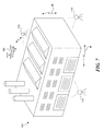
- FIG. 8 illustrates an arrangement for carrying out a scanning operation via equipment carried by a UAV in accordance with an embodiment of the present technology.
- FIG. 9A schematically illustrates a conventional process for scanning an object.
- FIG. 9B schematically illustrates a technique for selectively scanning features of an object in accordance with an embodiment of the present technology.
- FIG. 10 is a schematic block diagram illustrating a process for identifying and scheduling features to be scanned in accordance with an embodiment of the present technology.
- FIG. 11 is a flow diagram illustrating a process for planning and executing a flight path trajectory in accordance with an embodiment of the present technology.
- FIG. 12 illustrates a scanner positioned in an environment in accordance with an embodiment of the present technology.
- FIGS. 13A-13B illustrate isometric and plan views, respectively, of an image of the environment shown in FIG. 12 .
- FIG. 14 illustrates an image of another portion of the environment shown in FIG. 12 .
- FIGS. 15A-15C illustrate front, top, and side views of an environment that includes wind turbine, and an associated UAV flight path, in accordance with an embodiment of the present technology.
- FIGS. 16A-16D illustrate a process for obtaining data from wind turbine blades while the blades are in motion, in accordance an embodiment of the present technology.
- the present technology is directed generally to unmanned aerial vehicles (UAVs) and more particularly, to systems and methods for scanning the environments in which unmanned aerial vehicles operate, planning a flight for the unmanned aerial vehicles through one or more of the environments, and tracking the motion of the unmanned aerial vehicles in those environments.
- UAVs unmanned aerial vehicles
- Specific details of several embodiments of the disclosed technology are described below with reference to particular, representative configurations.
- the disclosed technology may be practiced in accordance with UAVs and associated systems having other configurations.
- particular aspects of the disclosed technology may be practiced in the context of autonomous vehicles other than UAVs (e.g., autonomous cars or watercraft).
- ⁇ may take the form of computer-executable instructions, including routines executed by a programmable computer or controller.
- the technology can be practiced on computer or controller systems other than those shown and described below.
- the technology can be embodied in a special-purpose computer, controller, or data processor that is specifically programmed, configured or constructed to perform one or more of the computer-executable instructions described below.
- the terms “computer” and “controller” as generally used herein include a suitable data processor and can include internet appliances and hand-held devices, including palm-top computers, wearable computers, cellular or mobile phones, multi-processor systems, processor-based or programmable consumer electronics, network computers, laptop computers, mini-computers and the like.
- LCD liquid crystal display
- the present technology can also be practiced in distributed environments, where tasks or modules are performed by remote processing devices that are linked through a communications network.
- program modules or subroutines may be located in local and remote memory storage devices.
- aspects of the technology described below may be stored or distributed on computer-readable media, including magnetic or optically readable or removable computer discs, as well as distributed electronically over networks. Data structures and transmissions of data particular to aspects of the technology are also encompassed within the scope of the present technology.
- FIGS. 1A-1C schematically identify several functions that can be performed as part of the technology disclosed in the present application.
- FIG. 1A illustrates a process for scanning an environment 190 in which a UAV is expected to operate.
- the environment 190 can be indoors and/or outdoors, and include one or more objects 191 , for example, a building.
- a system 100 in accordance with an embodiment of the present technology includes a scanner 110 that is used to scan the environment 190 and, in particular, the object or objects 191 , to produce a computer-based model 136 of the environment 190 .
- the scanner 110 can be controlled by a controller 130 .
- the same controller 130 can be used to perform a variety of additional functions, also described herein, in accordance with particular embodiments of the present technology.
- controllers may be referred to herein as “controllers,” and one or more controllers can be included in a “control system.”
- the controller 130 can have any of a variety of suitable configurations, e.g., a laptop computer configuration.
- the controller 130 can include a processor 131 , a memory 132 (e.g., non-transitory computer-readable media), and one or more input/output devices 133 .
- the input/output devices 133 can include an input device 134 (e.g., a keyboard) and an output device 135 (e.g., a screen displaying a graphical user interface).
- the output device 135 is displaying a computer-based object image 136 of the environment 190 , including the object 191 shown in FIG. 1A .
- the output device 135 also displays a proposed flight path image 137 , representing a proposed flight path for a UAV in the region of the object 191 .
- the controller 130 can be used to plan the UAV's flight path, e.g., by identifying obstacles in the flight path, alerting the operator to such obstacles, and/or suggesting or automatically implementing alternate flight paths.
- FIG. 1 C A further aspect of the system is illustrated in FIG. 1 C.
- the controller 130 and the scanner 110 can be used to track the motion of a UAV 150 as it operates in the environment 190 and around the object 191 .
- the scanner 110 can be used in this context to identify the actual location of the UAV 150 relative to the computer-based model of the object 191 , and can communicate this information to the UAV 150 via a communication device 138 (e.g., an antenna).
- the system 100 can be used to provide real-time data regarding the UAV's position and, by comparing that data to the model described above with reference to FIGS. 1A and 1B , can provide positional feedback to the UAV.
- the feedback can be used to adjust the UAV's actual flight path 151 , as necessary, in comparison to the planned flight path 137 to allow the UAV to carry out its mission with a high degree of precision and/or avoid collisions.
- the system 100 can be used to (a) map the environment in which the UAV operates, (b) facilitate defining a flight plan for the UAV in the environment, and (c) provide feedback to the UAV if it deviates from the flight plan. Further details of each of these functions are described below with reference to FIGS. 2-15C .
- FIG. 2 is a flow diagram illustrating a representative process for scanning an environment and tracking a UAV within the environment, in accordance with an embodiment of the present technology.
- the overall process can include the subprocesses of scanning, planning a flight path, and tracking the UAV. Depending on the embodiment, these subprocesses can be performed sequentially as part of a single overall process, or any of the subprocesses can be performed individually.
- the process 200 can include scanning the local environment with a ground or other off-board scanner (block 201 ).
- the scanner is located on the ground, e.g., supported by a tripod or another suitable structure. In other embodiments, the scanner can have other locations, e.g., it can be carried aloft by a balloon or aircraft.
- the process includes planning a flight path within the environment, where the flight path may be manually input by a human operator or calculated automatically based on various constraints.
- decision block 203 the process includes determining whether the planned path is achievable, for example, determining if the path is free of obstacles. If not, the process returns to block 202 for an update to the planned flight path. In various embodiments, the process can exclude detected obstacles when computing a revised path. If the path is achievable (e.g., is free of obstacles given the proximity constraints and dynamics of the UAV), the process proceeds to block 204 , which begins the tracking portion of the process. As part of this process, the system acquires a track on the UAV as it is in use, e.g., as it takes off and flies.
- this location information can be transmitted to the controller 130 that controls the tracking device in pan and tilt axes, continuously keeping the UAV within the field of view.
- the controller 130 launches the UAV (block 205 ) and directs the UAV to the beginning of its planned flight path (block 206 ).
- the UAV follows the flight path to its conclusion, and at block 208 lands at the end of the mission.
- the information received via tracking the UAV e.g., the coordinates of the UAV
- the information can be used to guide (e.g., automatically) the UAV back to the planned route.
- portions of the controller can be located on-board the UAV, off-board the UAV, or both, depending on the manner in which UAV control and feedback are implemented.
- the process includes checking, e.g., continually checking, to determine whether the UAV is successfully being tracked (block 209 ). As long as the UAV is being successfully tracked, the process continues as indicated. If the system loses track of the UAV, then in block 210 , the process includes taking actions to facilitate re-acquiring the track on the UAV. Such steps can include directing the UAV to hover, land, and/or fly toward the scanner, and/or performing a sweeping (and/or other) motion with the scanner to locate the UAV, and/or other suitable actions.
- the operator can manipulate the progress of the UAV along the flight path.
- the operator can use controls similar to VCR controls to fast-forward, reverse, or pause the progress of the UAV along the flight path.
- Such controls will be dependent on the UAV configuration, e.g., the UAV must have a hover capability in order for it to be paused.
- a similar approach can be used to preview the flight of the UAV along a proposed flight path, as part of the planning process for the flight path, which is described further below with reference to FIGS. 11-15C .
- FIG. 3 is an isometric illustration of a representative scanner 110 having features configured in accordance with an embodiment of the present technology.
- the scanner 110 can include a support 111 that carries a camera 117 and a rangefinder 118 .
- the camera 117 can be configured to produce two-dimensional optical images of the environment around the scanner 110 by receiving radiation from the environment in the visible spectrum, infrared range, and/or other suitable frequency ranges.
- the rangefinder 118 can include an emitter 119 and a receiver 120 .
- the emitter 119 emits a signal that reflects from an object in the environment and is received by the receiver 120 .
- the distance from the scanner 110 to the object is then determined or estimated by using any of a variety of suitable techniques, including estimating the amount of time required for the signal to transit from the emitter 119 to the object and back to the receiver 120 (“time of flight”). Accordingly, the camera 117 can identify and transmit two-dimensional information about the environment, and the rangefinder 118 can add the third dimension.
- the camera 117 and the rangefinder 118 can be carried by a tilt stage 114 and can be moved together as a unit to scan the environment around the scanner 110 .
- the tilt stage 114 carries a tilt motor 115 that rotates the camera 117 and the rangefinder 118 , as a unit, about a first axis (e.g., a horizontal axis H).
- a corresponding tilt encoder 116 tracks the motion of the camera 117 and the rangefinder 118 relative to the horizontal axis H.
- a pan motor 112 carried by the support 111 rotates the tilt stage 114 (including the camera 117 and the rangefinder 118 ) as a unit about a second axis (e.g., a vertical axis V).
- a pan encoder 113 tracks the rotational position of the camera 117 and the rangefinder 118 around the vertical axis V. Accordingly, the pan motor 112 and the tilt motor 115 can rotate to the camera 117 and the rangefinder 118 through arcs sufficient to cover a roughly hemispherical volume around the scanner 110 .
- the rangefinder 118 can include a lidar detector, which emits and receives laser light (e.g., IR laser light).
- Suitable lidar detectors have range capabilities in the hundreds of meters, depending on factors that include the size of the emitter 119 and receiver or detector 120 , and the ranging technology used.
- the ranging technology can include a time of flight technique in one embodiment.
- other techniques such as SETS techniques, can produce suitable results without requiring direct time of flight calculations, at lower cost and lower (but still suitable) resolution.
- the scans can be conducted in a methodical sweep pattern, or a coarse scan followed by a detailed scan, or an adaptive scan (described further below with reference to FIGS. 9A-10 ), or via another suitable technique.
- the rangefinder 118 can emit signals other than a laser signal, suitable for detecting the distance between the scanner 110 and the objects around it.
- a radar signal can be used for tracking, though it is expected that a laser signal will out-perform a radar signal for scanning.
- the laser scanner can be replaced by multiple high-resolution cameras or a structured light arrangement to perform the scanning process.
- FIG. 4 is a schematic block diagram illustrating the system 100 operating in a scanning mode, in accordance with an embodiment of the present technology.
- the camera 117 records images of the surrounding environment 190
- the rangefinder 118 records the distances to the objects within the environment 190 .
- the camera 117 accordingly generates RGB data (or other optical data) 123 and the rangefinder 118 generates depth or distance data 124 .
- the RGB data 123 is transmitted to the processor 131 .
- the depth data 124 is converted from spherical coordinates to Cartesian coordinates at the processor using conventional converter logic 125 that operates on information from the tilt encoder 116 and the pan encoder 113 .
- This transformed coordinate information is used to generate a point cloud from the data captured by the camera 117 and the rangefinder 118 using the point cloud builder logic 127 .
- the system 100 can also include a motor control unit that provides instructions to the tilt motor 115 and the pan motor 112 , and is itself under the control of a scan controller 430 .
- the scan controller 430 can include scan region logic 122 , which is described in further detail below with reference to FIGS. 9A-10 .
- the scan controller 430 can be a stand-alone controller, or it can be integrated with one or more other controllers, e.g., the controller 130 described above with reference to FIGS. 1A-1C .
- a power supply 126 provides power to the various components of the system 100 .
- the input/output device 133 receives information from an operator and provides output information to the operator.
- the result of the process performed during the scanning mode shown in FIG. 4 is a computer-based model (e.g., a point cloud) of the environment 190 .
- the data obtained during the scanning operation and used to build the three-dimensional model can be supplemented with additional data.
- the model can be augmented or enhanced with photographs or other sensor readings taken by the scanner camera 117 or by a UAV that flies through the scanned environment. This operation can be conducted in real time in some embodiments, and offline in others.
- the enhancement can include adding the color information contained in the camera image to the points in the point cloud to produce a more realistic, colored model displaying the spectral representation at each point.
- the data obtained from a particular scan can be stored and used later by the same scanner (e.g., in a track mode), or by a different scanner, also in the track mode, or by a UAV operating independently of an offboard tracking device.
- a tracker when a tracker is positioned in a particular area, it can automatically access prior scans made of that environment, and those scans can be downloaded to the scanner as it operates in the track mode.
- a particular scan may be used at multiple locations, not necessarily the same as the location at which the initial scan was made.
- a scan made of a particular wind turbine, power line tower, or other structure can be used to survey or inspect other structures that have an identical configuration, for example, wind turbines of the same make and model. In such cases, the scanned information can be calibrated to the particular location of an individual wind turbine, which may be different for each wind turbine.
- FIG. 5 illustrates the system 100 operating in a tracking mode.
- the camera 117 identifies a UAV 150 (e.g. by tracking a fiducial such as an LED carried by the UAV, by matching airframe characteristics as trained by a machine learning algorithm, or by other means) and generates two-dimensional tracking data 123 .
- the rangefinder 118 generates range data 561 corresponding to the distance between the scanner 110 and the UAV 150 , as the UAV flies.
- This information is provided to the processor 131 which generates an estimate of the position of the UAV 150 using position estimator logic 562 .
- the position information can be transmitted to the I/O device 133 , which can transmit the information via an information signal 563 to the UAV 150 .
- the UAV 150 can modify, adjust, and/or compensate for variations in the flight path it executes.
- the position information is also transmitted to the Motor Control Unit 121 which actuates the pan motor 112 and tilt motor 115 to continuously keep the UAV 150 within the field of view of the camera 117 and in front of the rangefinder 118 as the UAV flies.
- the system can track the UAV 150 by combining corner cube interferometry with a laser-based position sensing device to generate the position estimate for the UAV 150 .
- the position information can be transmitted to the I/O device 133 and UAV 150 so that it can modify, adjust, and/or compensate for variations in its flight path.
- the system can, in addition to transmitting information to the UAV 150 , receive information from the UAV 150 .
- the information received from the UAV 150 can correspond to an identity of the UAV 150 and/or an orientation of the UAV 150 .
- FIGS. 6A and 6B illustrate a representative UAV 650 having a body 652 and one or more rotors 653 (four are shown in FIGS. 6A and 6B ) for propulsion.
- the UAV 650 can also include a physical encoding schema, for example a ring 654 or lighting system that in turn includes one or more coding patterns 655 ( FIG. 6B ).
- the coding patterns 655 can be used to identify the type of UAV detected by the scanner 110 ( FIG.
- the coding patterns 655 can perform the function of an identifying fiducial.
- the coding patterns 655 can have different characteristics at different circumferential positions around the coding ring 654 . Accordingly, when the system 100 detects the coding patterns 655 , it can detect the orientation of the UAV 650 . This information can in turn be used to help control, guide, and/or direct the UAV 650 . To obtain this information, the camera 117 (or a separate, dedicated camera) can obtain an image of the coding patterns, which is then processed (e.g., in the manner of a bar coder). In another embodiment, the system 100 can issue an inquiry signal 664 (e.g., in addition to the information signal 563 ) that impinges on and is reflected by the coding pattern 655 .
- an inquiry signal 664 e.g., in addition to the information signal 563
- the reflected signal is then processed to determine the orientation and/or identity of the UAV 650 .
- the coding pattern 655 is passive. In other embodiments, the coding pattern 655 can be actively transmitted by the UAV 650 , e.g., via a radio emission, an LED pattern or flash sequence, and/or other suitable arrangements.
- orientation function described above is that it may be more accurate than the orientation function provided by an on-board inertial navigation system.
- on-board inertial navigation systems typically include a magnetometer, which can be affected by nearby structures, e.g., magnetic or metal structures.
- the off-board scanner can provide orientation information that is unaffected by such structures, allowing the UAV to operate in environments it might not otherwise be able to.
- a single scanner may be insufficient to provide all the data required for the UAV to carry out its tasks.
- a target object 791 may include a building having target features that are not accessible to a single scanner at a single location.
- the scanner 110 is moved among multiple locations to provide sufficient data for the desired point cloud. At each location, the scanner 110 obtains two-dimensional image data and depth data, as discussed above, and the multiple data sets can be “stitched” together to form a composite computer model.
- multiple scanners 110 can be used to both scan the features of the building, and provide tracking for the UAV 150 as it flies its mission.
- the scanners 110 can communicate with each other, as indicated by arrows M so as to hand off tracking responsibility from one scanner to the other as the UAV 150 conducts its mission.
- the scanning function can be performed by a UAV 850 itself.
- the scanning equipment is made compact and lightweight enough to be carried by the UAV 850 .
- the scanning equipment may be compromised in some manner to reduce its weight.
- the scanning equipment may have a coarser resolution, reduced range, reduced field of view and/or other weight-saving features.
- the UAV 850 can assume the positions identified by letters A, B, C and D to map the features of the building 791 . After mapping the features, the UAV 850 can carry out its mission, as indicated by letter E.
- the tracking function described above with reference to FIG. 5 may be performed by comparing images taken by the UAV 850 while it is in flight, with point cloud information produced by scans taken by the UAV while it is on the ground at positions A-D.
- the tracking operation is carried out by two UAVs 850 , each equipped with a scanner. Accordingly, one UAV 850 can fly a mission (e.g., an inspection mission) and the second UAV 850 can track the first UAV 850 .
- the tracking function can be performed from any of the scanning positions A-D described above, or (with accommodations for an offset) from a different location.
- the system can perform still further functions directed to tracking the UAVs. For example, in the track mode, the system can scan the environment to determine if a UAV is in the area. Upon detecting the UAV, the tracker can use any of the arrangements described above to identify the UAV and, optionally, its orientation. The tracker can also communicate with UAVs that are out of visual range or beyond line of sight (BLOS). Such UAVs can relay their position and trajectory to the tracker (for example, via GPS and radio communication) and the tracker can accordingly orient itself toward the position where the UAV is expected to come within range. Once the UAV comes within range, the tracker can carry out the tracking operations described above. In other embodiments, the UAV can be tracked using ADS-B in addition to, or in lieu of GPS.
- ADS-B in addition to, or in lieu of GPS.
- the system can scan a pre-scanned environment to check for new objects that may have entered the environment after the initial scan was completed.
- new objects can include a UAV, or other objects that may represent obstacles to a UAV. If such objects are detected, the three-dimensional model of the environment can be updated to reflect the existence of those objects.
- some arrangements can include multiple scanners for performing scanning and/or tracking functions.
- these scanners can communicate with each other to provide continuity within the three-dimensional models that they create, and to transmit information related to UAVs in their individual environments.
- the scanners can cooperate to give control priority to the scanner that is closest to the UAV, or that is projected to have the longest contact with the UAV before a handoff.
- the system can schedule on-board photo/recording/sensing functions. For example, it may be advantageous to direct the UAV to perform a sensing function from a precise location.
- the scanner When the scanner is performing in the tracking mode, it can alert the UAV when the UAV reaches the precise location, in real time, to ensure that the sensing function is performed at the proper location.
- This technique can also be used to capture an image of the UAV when it is in a particular location, using the ground-based camera portion of the scanner. In this manner, the UAV can capture an image at a particular location, and the scanner can capture an image of the UAV at that location. Both techniques can be used to improve the reproducibility of data, e.g., if the same image is to be obtained at different times.
- the UAV position information from the tracker can be used to reduce computation and improve the fit of photos to the cloud of points. For example, the downstream analysis of the data can be simpler and/or more accurate when the data are tagged with the precise location from which the data were taken.
- FIG. 9A illustrates an object 991 being scanned by a scanner 110 in accordance with a conventional scanning technique.
- the scanner 110 methodically and sequentially pans and tilts to produce scan paths 994 a (shown in dotted lines) that cover the object 991 .
- This process can be time-consuming, particularly when only certain features of the object 991 may be of real interest to the end user. For example, the end user may be more interested in certain target features 992 .
- the target features 992 can include straight lines that form target regions 993 , for example, the roof and windows of the building.
- FIG. 9B illustrates the scanner 110 carrying out an adaptive scan routine in accordance with an embodiment of the present technology.
- the scan paths 994 b executed by the scanner 110 are directed specifically to the target features 992 and therefore the target regions 993 .
- the scanner 110 spends less time unnecessarily scanning features that are not of interest. Accordingly, the process of scanning the object 991 can take significantly less time than it does using conventional techniques, and can use significantly fewer resources.
- FIG. 10 is a block diagram illustrating a process for carrying out the scanning operation shown in FIG. 9B .
- An overall process 1000 in accordance with an embodiment of the present disclosure includes an image processing block 1001 that in turn includes an image acquisition block 1002 .
- the process includes acquiring image data, e.g., from the camera 117 .
- the image data are analyzed, for example to identify particular features, and more particularly, features that are likely to be of interest, e.g., by an end user. Such features can include lines, corners, and/or other target shapes, or features that may be identified by a user.
- Block 1005 and 1006 include classifying each of the target regions, for example, by selecting regions that are of interest for targeted scanning by the rangefinder 118 (block 1009 ).
- This process can be performed manually, automatically, or via a combination of manual and automated techniques.
- the process can include using computer-based shape recognition routines to identify target features (or target regions) and a user can approve or reject the automatically generated selections.
- the user can assume full control of the selection process (fully manual) or cede control (fully automated).
- algorithms such as Hough transforms are used to identify features and/or regions of interest.
- a scheduler 1007 collects the information for each region and identifies an optimal (or at least expedient) scan path (block 1008 ).
- the scan controller 430 ( FIG. 4 ) directs the camera 117 and the associated rangefinder 118 ( FIG. 4 ) along the scan paths identified at block 1008 .
- the output (block 1010 ) is a three-dimensional model, which the UAV uses to navigate and perform its mission.
- FIGS. 11-15C illustrate representative processes for forming or defining flight paths in accordance with which the UAV conducts its mission in the environment scanned by the scanner, as described above.
- a representative process 1100 shown in FIG. 11 includes scanning the environment or importing a three-dimensional model of the environment (block 1101 ).
- the process includes constructing a flight path within the environment.
- the flight path is constructed using user input 1103 .
- the user can view the three-dimensional model on a computer screen and, via a mouse, keys, a joystick, and/or other input devices, construct the flight path. Because the flight path is three-dimensional, the system can allow the user to rotate the image in any manner (e.g., tumble the image) so as to view the environment from multiple perspectives and provide a suitable three-dimensional flight path.
- the flight path can be automatically generated, as indicated by block 1104 .
- the process may require additional inputs 1105 .
- Such inputs can include a general characterization of the desired flight path, for example, an identification of the regions of interest and the distance away from the regions of interest that the UAV is to fly. It may be of particular importance to maintain a set distance from an object, (a) to prevent collisions with the object, and/or (b) to keep the object within the target range of a sensor aboard the UAV.
- the information can include the speed of the UAV, the flight dynamics and capabilities of the UAV, and any restrictions or limitations associated with the ability of the UAV to point its camera or other sensor toward the target region.
- the system can automatically generate a flight path.
- the flight path can be a single-pass path or a multi-pass path (e.g., a “lawnmower” pattern) depending on factors including the field of view of the UAV-based sensor, and the desired resolution of the object it senses.
- Block 1106 includes calculating a predicted trajectory based on the UAV path determined at block 1102 , taking into account the speed of the UAV, the flight dynamics and capabilities of the UAV, and other restrictions as described above.
- Block 1107 includes checking to determine if the path is free of collisions, for example, collisions with the objects represented in the model imported at block 1101 . If the path does include collisions (or greater than a threshold likelihood of collisions), the process returns to block 1102 for adjustments to the flight path. As an example, the process can prevent areas of the path that are causing the collisions from being included in a subsequent construction of a suitable path. If not, then the flight path can be initiated and executed, as indicated at block 1108 .
- FIG. 12 illustrates the scanner 110 in a representative environment 1290 that includes first objects (e.g., statues 1291 a ) and second objects (e.g., buildings 1291 b ).
- FIG. 13A illustrates the computer-based model of the environment, including the statues 1291 a and the buildings 1291 b , based on data obtained from the scanner 110 .
- FIG. 13A also illustrates a proposed flight path 1337 that may be constructed by a user viewing the pointcloud of the environment 1336 .
- FIG. 13B is a plan view (top-down) of the pointcloud environment 1336 shown in FIG. 13A .
- the user can toggle between preset views (e.g., plan view, side view, front view, etc.), or can move gradually and incrementally at any pace from one view to another by tumbling around the pointcloud environment 1336 .
- FIG. 14 illustrates one of the buildings 1291 b shown in FIGS. 13A and 13B along with the proposed flight path 1337 .
- the proposed flight path 1337 includes an interfering portion 1337 a where the UAV would collide with, or come too close to, the building 1291 b .
- the user is alerted to the interference, for example, by displaying the interfering portion 1337 a of the flight path in a different color than the non-interfering portion.
- the system can use other alerting techniques (e.g., flashing lights, and/or an audible signal). Additionally, the system can prevent the user from flying the mission until the interfering portion is removed, e.g. by modifying the flight path.
- FIGS. 15A, 15B, and 15C are front, top, and side views of an object 1591 that includes a wind turbine 1591 .
- FIGS. 15A-C also illustrate a flight path 1551 along which a UAV 150 flies to examine the wind turbine 1591 , and a (schematic) field of view 1593 for the ground-based scanner.
- the three-view illustration is suitable for indicating to the user that no collisions or likely collisions exist for the UAV 150 .
- the image may also be tumbled or otherwise rotated to provide this information to the user.
- the data collected by the scanner can be used to aid the UAV in performing at least two functions. First, the data can be used to aid the UAV in carrying out the substance of its mission.
- the mission may include inspecting the blades of a wind turbine.
- the image data can provide an accurate indication of the location of the blades and/or other areas of interest that the UAV may focus on as part of its mission.
- the data can aid the UAV in avoiding obstacles as it carries out its mission.
- the image data can allow the UAV to avoid striking the pylon 1592 that carries the wind turbine blades.
- the wind turbine 1591 is stopped while the UAV 150 performs its inspection.
- the UAV 150 can perform the inspection while the turbine blades are spinning, as illustrated in a representative embodiment shown in FIGS. 16A-16D .
- the wind turbine 1591 includes the pylon 1592 described above, which carries three blades 1595 .
- the blades 1595 When the blades 1595 are in motion, they sweep out a disk D.
- Each blade 1595 can include multiple regions extending inwardly from the blade tips. Two representative regions are illustrated in FIGS. 16A-16D as a first region 1596 a and a second region 1596 b .
- the UAV 150 moves to a first position P 1 located toward the outer periphery of the disk D, so as to be aligned with the first regions 1596 a of each blade 1595 as the blades pass by.
- the first region 1596 a of one of the blades 1595 has rotated into the field of view 1597 of a sensor carried by the UAV 150 .
- the sensor is activated.
- the sensor includes a camera
- the camera is activated to take an image of the first region 1596 a .
- the UAV 150 can remain in the first position P 1 and, as the first region 1596 a of each successive blade 1595 passes into the field of view 1597 , the UAV 150 can activate the sensor to take an image or collect other data.
- the UAV 150 can move to a second position P 2 , as shown in FIG. 16C . From the second position P 2 , the UAV 150 can image or otherwise sense the second regions 1596 b of each blade 1595 , as shown in FIG. 16D .
- the foregoing process can be repeated for additional regions of interest, e.g., regions located inwardly from the second region 1596 b toward the hub 1599 from which the blades 1595 extend.
- An advantage of the foregoing approach is that the wind turbine 1591 need not be halted while the UAV 150 obtains diagnostic information, including but not limited to image data of the blades 1595 . This in turn can increase the run time of the wind turbine 1591 without compromising on the need for obtaining periodic diagnostic data.
- the system can include a combination of a camera (or other two-dimensional imaging device) and a laser scanner (or other rangefinder) to map out an environment in which a UAV is expected to fly.
- a camera or other two-dimensional imaging device
- a laser scanner or other rangefinder
- One advantage of this arrangement is that it is relatively inexpensive when compared to traditional surveying laser scanners, or spinning lidar devices.
- Another advantage of the foregoing arrangement is that it provides capabilities different than those of existing systems. For example, existing surveying rangefinders operate at about 0.5-1 Hz and provide resolution at a millimeter or sub-millimeter level.
- Embodiments of the present system operate at rates of 50 Hz-100 Hz, which (unlike a 1 Hz rate) are sufficient to keep pace with the flight speeds and offset distances of typical UAVs.
- the resolution of embodiments of the present system can be reduced to the centimeter level, which is sufficient for typical UAV tasks, and reduces the cost of the system.
- Yet another expected advantage of embodiments of the disclosed systems is that they can be located off-board the UAV and therefore do not require the UAV to provide payload capacity and processing power for the scanning and mapping equipment. Instead, the payload capacity can be reserved for mission-performance equipment, and the power can be conserved for conducting the UAV's mission. This feature can be particularly important for UAVs that have limited battery capacity. Still another advantage is that the combined scanner and rangefinder arrangement is compact and is therefore more portable than other mapping equipment, for example, equipment that includes an array of infrared cameras.
- the scanner can perform a tracking function, in addition to a scanning function.
- An advantage of this feature is that the UAV can be told what its position is from an off-board source on roughly the same time scale at which it is flying. In particular, the UAV can receive updates multiple times per second, and at a rate that allows it to change course if necessary, for example, to avoid obstacles.
- Another advantage of this feature is that the UAV's position can be continually compared to a pre-defined flight path that has been defined using an accurate, three-dimensional model of the local environment. Accordingly, the likelihood for the UAV to get off track is reduced, and if the UAV does get off track, the system can redirect the UAV with a high degree of accuracy.
- the process for planning a flight can be automated, semi-automated, and/or more visually interactive than conventional waypoint planning arrangements.
- An advantage of this arrangement is that it can speed up the process for flightpath planning, particularly, in cluttered local environments.
- Another advantage is that the flight path can be more accurate, which again has particular utility in GPS-denied or crowded areas where GPS is either unavailable or insufficient to provide the level of detail required to navigate through such areas.
- the interface can be intuitive. This is so for at least the reason that the objects presented at the interface are visually representative of the objects as they actually appear. A building looks like a building, a tree looks like a tree, etc.
- Still another advantage is that the interface can better simulate (via rotation or tumbling) the actual three-dimensional environment, and the user can appreciate the three-dimensional nature of the flight environment by rotating the image so as to see obstacles and targets of interest from multiple angles. This is unlike typical flight planning arrangements in which the user has to imagine the height of obstacles. Still another advantage is that at least some aspects of the flight planning process can be automated. For example, the user can input a representative flight path, which can be automatically evaluated for collision problems. The flight path can also automatically be adjusted to provide a constant offset from a particular object, for example, a wind turbine blade that is being inspected by the UAV flying along the flight path.
- the process for obtaining the data used to build the three-dimensional model can be adapted to account for the environment that is scanned.
- the scanning process can be focused on areas of interest, rather than the environment as a whole.
- An advantage of this approach is that the process for scanning the environment can be faster because areas that are similar (e.g., large flat surfaces) and areas that are physically unscannable (e.g., the sky) may be avoided and therefore do not take time to map.
- Another advantage is that the limited number of data points available for a particular model can be focused on the areas of interest so that those areas are modeled with greater resolution than areas that are of less importance.
- the overall number of points required to define a particular model can be reduced. Still further, the demands on (and therefore the cost of) the scanning motors are reduced when fewer data points are taken. This approach can reduce the cost/complexity of the overall system.
- the scanner 110 remains in the same position for both the scanning operation and the tracking operation. In other embodiments, the scanner may be moved between these two operations.
- the process for tracking the UAV can include accounting for an offset between the position at which the scanner conducted the scan, and the position from which the scanner tracks the UAV.
- the offset can be determined using GPS and/or other suitable techniques.
- a particular scan may be tagged with its GPS coordinates so that it can be used for multiple missions, each of which may have the tracker at a different location.
- the GPS coordinates from which the initial scan is made can provide a constant reference point suitable for multiple uses.
- a local coordinate system can be used in lieu of GPS.
- the fiducial carried by the UAV can take the form of a coding pattern, as described above.
- the fiducial can include other arrangements, for example, an LED or LED pattern.
- the scanner when in the track mode, can identify the UAV by matching certain characteristics of the UAV (e.g., its silhouette) with a library of pre-identified silhouettes as trained by machine learning algorithms, e.g. a deep neural network.
- the tracking mode includes tracking coordinates.
- the tracking mode can include tracking the direction of travel, the UAV speed, and/or other variables, in addition to or in lieu of tracking the vehicle coordinates.
- the tracking process and the associated scanning process can be performed outdoors, as shown in several of the Figures above, and can also be performed indoors.
- the system can cycle or oscillate between the scanning mode and the tracking mode, even when used in the same environment, for example, to detect changes in the environment. Such changes can then be imported into the point cloud or other computer-based image file so as to update the associated three-dimensional model.
- Particular embodiments of the system were described above in the context of a quad-rotor UAV, and in other embodiments, the UAV can have other quad-rotor or non-quad-rotor configurations.
- the scanner can have different arrangements in different embodiments.
- the camera and rangefinder each have independent optical paths to the environment and the UAV.
- a prism or other beam splitter provides identical optical information to both the camera and the rangefinder. This approach can improve the correspondence between information provided by the camera and information provided by the rangefinder.
- the scanner can include devices other than a single camera and a single rangefinder, e.g., multiple cameras (having different fields of view, wavelength sensitivities, and/or other functional parameters) and/or multiple rangefinders (having different sensitivities over different distances, and/or other functional parameters).
- the flight path planning algorithm described above can be used independently of the scanning and tracking processes described above.
- the adaptive scanning techniques described above can be used independently of the tracking and/or flight planning processes described above.
Priority Applications (2)
| Application Number | Priority Date | Filing Date | Title |
|---|---|---|---|
| US15/059,030 US10671066B2 (en) | 2015-03-03 | 2016-03-02 | Scanning environments and tracking unmanned aerial vehicles |
| US16/849,924 US20210064024A1 (en) | 2015-03-03 | 2020-04-15 | Scanning environments and tracking unmanned aerial vehicles |
Applications Claiming Priority (2)
| Application Number | Priority Date | Filing Date | Title |
|---|---|---|---|
| US201562127476P | 2015-03-03 | 2015-03-03 | |
| US15/059,030 US10671066B2 (en) | 2015-03-03 | 2016-03-02 | Scanning environments and tracking unmanned aerial vehicles |
Related Child Applications (1)
| Application Number | Title | Priority Date | Filing Date |
|---|---|---|---|
| US16/849,924 Continuation US20210064024A1 (en) | 2015-03-03 | 2020-04-15 | Scanning environments and tracking unmanned aerial vehicles |
Publications (2)
| Publication Number | Publication Date |
|---|---|
| US20160292872A1 US20160292872A1 (en) | 2016-10-06 |
| US10671066B2 true US10671066B2 (en) | 2020-06-02 |
Family
ID=56848680
Family Applications (4)
| Application Number | Title | Priority Date | Filing Date |
|---|---|---|---|
| US15/059,101 Active 2036-07-31 US10416668B2 (en) | 2015-03-03 | 2016-03-02 | Scanning environments and tracking unmanned aerial vehicles |
| US15/059,069 Active US10162353B2 (en) | 2015-03-03 | 2016-03-02 | Scanning environments and tracking unmanned aerial vehicles |
| US15/059,030 Active US10671066B2 (en) | 2015-03-03 | 2016-03-02 | Scanning environments and tracking unmanned aerial vehicles |
| US16/849,924 Abandoned US20210064024A1 (en) | 2015-03-03 | 2020-04-15 | Scanning environments and tracking unmanned aerial vehicles |
Family Applications Before (2)
| Application Number | Title | Priority Date | Filing Date |
|---|---|---|---|
| US15/059,101 Active 2036-07-31 US10416668B2 (en) | 2015-03-03 | 2016-03-02 | Scanning environments and tracking unmanned aerial vehicles |
| US15/059,069 Active US10162353B2 (en) | 2015-03-03 | 2016-03-02 | Scanning environments and tracking unmanned aerial vehicles |
Family Applications After (1)
| Application Number | Title | Priority Date | Filing Date |
|---|---|---|---|
| US16/849,924 Abandoned US20210064024A1 (en) | 2015-03-03 | 2020-04-15 | Scanning environments and tracking unmanned aerial vehicles |
Country Status (5)
| Country | Link |
|---|---|
| US (4) | US10416668B2 (ja) |
| EP (1) | EP3265885A4 (ja) |
| JP (1) | JP6843773B2 (ja) |
| CA (1) | CA2977945A1 (ja) |
| WO (1) | WO2016141100A2 (ja) |
Families Citing this family (111)
| Publication number | Priority date | Publication date | Assignee | Title |
|---|---|---|---|---|
| US8874360B2 (en) * | 2012-03-09 | 2014-10-28 | Proxy Technologies Inc. | Autonomous vehicle and method for coordinating the paths of multiple autonomous vehicles |
| WO2015175440A1 (en) * | 2014-05-12 | 2015-11-19 | Unmanned Innovation, Inc. | Unmanned aerial vehicle authorization and geofence envelope determination |
| US9978030B2 (en) * | 2014-06-11 | 2018-05-22 | Hartford Fire Insurance Company | System and method for processing of UAV based data for risk mitigation and loss control |
| WO2016141100A2 (en) | 2015-03-03 | 2016-09-09 | Prenav Inc. | Scanning environments and tracking unmanned aerial vehicles |
| WO2016161637A1 (en) * | 2015-04-10 | 2016-10-13 | SZ DJI Technology Co., Ltd. | Method, apparatus and system of providing communication coverage to an unmanned aerial vehicle |
| US9936138B2 (en) | 2015-07-29 | 2018-04-03 | Samsung Electronics Co., Ltd. | User terminal apparatus and control method thereof |
| US11284003B2 (en) | 2015-07-29 | 2022-03-22 | Samsung Electronics Co., Ltd. | User terminal apparatus and control method thereof |
| US10282591B2 (en) * | 2015-08-24 | 2019-05-07 | Qualcomm Incorporated | Systems and methods for depth map sampling |
| US9772395B2 (en) | 2015-09-25 | 2017-09-26 | Intel Corporation | Vision and radio fusion based precise indoor localization |
| NL2015843B1 (en) * | 2015-11-23 | 2017-06-07 | Daf Trucks Nv | Auto docking method for application in heavy trucks. |
| EP3391339A2 (en) | 2015-12-18 | 2018-10-24 | Iris Automation, Inc. | Real-time visual situational awareness system |
| CA2952484A1 (en) * | 2015-12-23 | 2017-06-23 | Wal-Mart Stores, Inc. | Apparatus and method for monitoring premises |
| US10853756B2 (en) * | 2016-03-02 | 2020-12-01 | International Business Machines Corporation | Vehicle identification and interception |
| US10188580B2 (en) * | 2016-05-09 | 2019-01-29 | Toyota Motor Engineering & Manufacturing North America, Inc. | Systems and methods for providing environment information using an unmanned vehicle |
| US10054445B2 (en) | 2016-05-16 | 2018-08-21 | Northrop Grumman Systems Corporation | Vision-aided aerial navigation |
| US10309792B2 (en) | 2016-06-14 | 2019-06-04 | nuTonomy Inc. | Route planning for an autonomous vehicle |
| US11092446B2 (en) * | 2016-06-14 | 2021-08-17 | Motional Ad Llc | Route planning for an autonomous vehicle |
| JP6713847B2 (ja) * | 2016-06-14 | 2020-06-24 | 株式会社トプコン | 測量システム |
| US11149717B2 (en) * | 2016-06-30 | 2021-10-19 | Skydio, Inc. | Unmanned aerial vehicle wind turbine inspection systems and methods |
| US10165168B2 (en) * | 2016-07-29 | 2018-12-25 | Microsoft Technology Licensing, Llc | Model-based classification of ambiguous depth image data |
| CN107223219B (zh) * | 2016-09-26 | 2020-06-23 | 深圳市大疆创新科技有限公司 | 控制方法、控制设备和运载系统 |
| US10210905B2 (en) | 2016-09-30 | 2019-02-19 | Sony Interactive Entertainment Inc. | Remote controlled object macro and autopilot system |
| US10357709B2 (en) | 2016-09-30 | 2019-07-23 | Sony Interactive Entertainment Inc. | Unmanned aerial vehicle movement via environmental airflow |
| US10336469B2 (en) | 2016-09-30 | 2019-07-02 | Sony Interactive Entertainment Inc. | Unmanned aerial vehicle movement via environmental interactions |
| US10410320B2 (en) | 2016-09-30 | 2019-09-10 | Sony Interactive Entertainment Inc. | Course profiling and sharing |
| JP6947962B2 (ja) * | 2016-09-30 | 2021-10-13 | キヤノンマーケティングジャパン株式会社 | 無人航空機制御システム、その制御方法、及びプログラム |
| US10377484B2 (en) | 2016-09-30 | 2019-08-13 | Sony Interactive Entertainment Inc. | UAV positional anchors |
| US10679511B2 (en) * | 2016-09-30 | 2020-06-09 | Sony Interactive Entertainment Inc. | Collision detection and avoidance |
| US11125561B2 (en) | 2016-09-30 | 2021-09-21 | Sony Interactive Entertainment Inc. | Steering assist |
| US10850838B2 (en) | 2016-09-30 | 2020-12-01 | Sony Interactive Entertainment Inc. | UAV battery form factor and insertion/ejection methodologies |
| JP6899500B2 (ja) * | 2016-10-17 | 2021-07-07 | イームズロボティクス株式会社 | 移動体捕獲装置、移動体捕獲方法及びプログラム |
| US10803757B2 (en) | 2016-10-23 | 2020-10-13 | Gopro, Inc. | Navigation through polygonal no fly zones |
| DE102016120196A1 (de) * | 2016-10-24 | 2018-04-26 | Deutsches Zentrum für Luft- und Raumfahrt e.V. | Verfahren und Vorrichtung zum automatischen Ermitteln von positions- und/oder bewegungsbezogenen Zustandsinformationen eines Fahrzeuges |
| US9886632B1 (en) | 2016-11-04 | 2018-02-06 | Loveland Innovations, LLC | Systems and methods for autonomous perpendicular imaging of test squares |
| US9823658B1 (en) | 2016-11-04 | 2017-11-21 | Loveland Innovations, LLC | Systems and methods for adaptive property analysis via autonomous vehicles |
| US10901420B2 (en) | 2016-11-04 | 2021-01-26 | Intel Corporation | Unmanned aerial vehicle-based systems and methods for agricultural landscape modeling |
| US10521664B2 (en) | 2016-11-04 | 2019-12-31 | Loveland Innovations, LLC | Systems and methods for autonomous perpendicular imaging of test squares |
| US9734397B1 (en) | 2016-11-04 | 2017-08-15 | Loveland Innovations, LLC | Systems and methods for autonomous imaging and structural analysis |
| US10568063B2 (en) * | 2016-11-30 | 2020-02-18 | Cisco Technology, Inc. | Precise UAV tracking in 3-D space |
| CN109997091B (zh) | 2016-12-01 | 2022-08-09 | 深圳市大疆创新科技有限公司 | 用于管理3d飞行路径的方法和相关系统 |
| JP6817806B2 (ja) * | 2016-12-21 | 2021-01-20 | 株式会社トプコン | 演算装置、演算方法、演算システムおよびプログラム |
| WO2018116487A1 (ja) * | 2016-12-22 | 2018-06-28 | 日本電気株式会社 | 追跡支援装置、端末、追跡支援システム、追跡支援方法及びプログラム |
| JP6826888B2 (ja) * | 2017-01-11 | 2021-02-10 | 株式会社トプコン | 測量装置、無人航空機の探索方法、測量システムおよびプログラム |
| US11017679B2 (en) * | 2017-01-13 | 2021-05-25 | Skydio, Inc. | Unmanned aerial vehicle visual point cloud navigation |
| US10893190B2 (en) | 2017-02-02 | 2021-01-12 | PreNav, Inc. | Tracking image collection for digital capture of environments, and associated systems and methods |
| US9805261B1 (en) | 2017-02-27 | 2017-10-31 | Loveland Innovations, LLC | Systems and methods for surface and subsurface damage assessments, patch scans, and visualization |
| DE102017104490A1 (de) * | 2017-03-03 | 2018-09-06 | Innogy Se | Inspektionsgerätsteuerungseinrichtung für ein Inspektionsgerät einer Windkraftanlage |
| US10329017B2 (en) * | 2017-03-13 | 2019-06-25 | General Electric Company | System and method for integrating flight path and site operating data |
| DE102017205647A1 (de) | 2017-03-14 | 2018-09-20 | Bitmanagement Software GmbH | Verfahren zum bestimmen eines pfades entlang eines objekts, system und verfahren zum automatischen inspizieren eines objekts |
| KR101928454B1 (ko) * | 2017-03-21 | 2018-12-12 | 주식회사 한 지아이에스 | 군집 비행용 무인비행선 및 이의 제어방법 |
| KR101928451B1 (ko) * | 2017-03-21 | 2018-12-12 | 주식회사 한 지아이에스 | 실내 검사용 무인비행선 |
| CN110537109B (zh) * | 2017-04-28 | 2024-02-20 | 深圳市大疆创新科技有限公司 | 用于自主驾驶的感测组件 |
| US10012735B1 (en) | 2017-05-04 | 2018-07-03 | Loveland Innovations, LLC | GPS offset calibrations for UAVs |
| US10984182B2 (en) | 2017-05-12 | 2021-04-20 | Loveland Innovations, LLC | Systems and methods for context-rich annotation and report generation for UAV microscan data |
| CN107218926B (zh) * | 2017-05-12 | 2020-04-03 | 西北工业大学 | 一种基于无人机平台的远程扫描的数据处理方法 |
| US10520948B2 (en) | 2017-05-12 | 2019-12-31 | Autonomy Squared Llc | Robot delivery method |
| US10445871B2 (en) * | 2017-05-22 | 2019-10-15 | General Electric Company | Image analysis neural network systems |
| CA3066907A1 (en) * | 2017-06-13 | 2018-12-20 | PreNav, Inc. | Active tethers for controlling uav flight volumes, and associated methods and systems |
| US10642264B2 (en) * | 2017-07-19 | 2020-05-05 | Superior Communications, Inc. | Security drone system |
| US10545500B2 (en) * | 2017-08-02 | 2020-01-28 | Wing Aviation Llc | Model for determining drop-off spot at delivery location |
| CN109406353B (zh) * | 2017-08-16 | 2024-04-09 | 深圳智人环保科技有限公司 | 一种无人机、空气污染监测系统及方法 |
| US10338592B2 (en) * | 2017-08-24 | 2019-07-02 | Saudi Arabian Oil Company | High accuracy remote coordinate machine |
| PT3454159T (pt) * | 2017-09-06 | 2020-03-11 | Alerion Tech S L | Método e dispositivo de navegação autónoma |
| US10679493B2 (en) * | 2017-09-18 | 2020-06-09 | International Business Machines Corporation | Cognitive-based incident response |
| JP7086554B2 (ja) * | 2017-09-29 | 2022-06-20 | 株式会社トプコン | 無人航空機の制御方法および無人航空機の制御用プログラム |
| LT3694314T (lt) * | 2017-10-10 | 2022-03-10 | Basf Se | Bent vieno akvakultūros tvenkinio stebėsenos būdas ir akvakultūros tvenkinio stebėsenos sistema |
| WO2019077685A1 (ja) * | 2017-10-17 | 2019-04-25 | 本田技研工業株式会社 | 走行モデル生成システム、走行モデル生成システムにおける車両、処理方法およびプログラム |
| US10802483B2 (en) * | 2017-10-19 | 2020-10-13 | International Business Machines Corporation | Emergency public deactivation of autonomous vehicles |
| US10364027B2 (en) | 2017-10-24 | 2019-07-30 | Loveland Innovations, LLC | Crisscross boustrophedonic flight patterns for UAV scanning and imaging |
| JP7077013B2 (ja) * | 2017-12-27 | 2022-05-30 | 株式会社トプコン | 三次元情報処理部、三次元情報処理部を備える装置、無人航空機、報知装置、三次元情報処理部を用いた移動体制御方法および移動体制御処理用プログラム |
| JP2019075075A (ja) * | 2018-03-28 | 2019-05-16 | 株式会社自律制御システム研究所 | 無人航空機の飛行計画経路を設定するためのシステム及びプログラム |
| JP6452183B1 (ja) * | 2018-03-30 | 2019-01-16 | 株式会社amuse oneself | 釣り動画撮像システム |
| US10916150B2 (en) * | 2018-05-03 | 2021-02-09 | Arkidan Systems Inc. | Computer-assisted aerial surveying and navigation |
| US11255975B2 (en) * | 2018-06-05 | 2022-02-22 | Pony Ai Inc. | Systems and methods for implementing a tracking camera system onboard an autonomous vehicle |
| US11205072B2 (en) | 2018-08-24 | 2021-12-21 | Loveland Innovations, LLC | Solar ray mapping via divergent beam modeling |
| US10366287B1 (en) | 2018-08-24 | 2019-07-30 | Loveland Innovations, LLC | Image analysis and estimation of rooftop solar exposure |
| US11210514B2 (en) | 2018-08-24 | 2021-12-28 | Loveland Innovations, LLC | Image analysis and estimation of rooftop solar exposure via solar ray mapping |
| KR102108170B1 (ko) * | 2018-09-19 | 2020-05-08 | 인하대학교 산학협력단 | 골프 드론 |
| JP2022502663A (ja) * | 2018-10-02 | 2022-01-11 | フォルテム テクノロジーズ,インコーポレイテッド | ドローンおよび物体の分類のためのシステムおよび方法 |
| US11585933B2 (en) | 2018-10-29 | 2023-02-21 | Lawrence Livermore National Security, Llc | System and method for adaptive object-oriented sensor fusion for environmental mapping |
| WO2020103049A1 (zh) * | 2018-11-21 | 2020-05-28 | 深圳市大疆创新科技有限公司 | 旋转微波雷达的地形预测方法、装置、系统和无人机 |
| US11203445B2 (en) * | 2018-12-11 | 2021-12-21 | The Boeing Company | Data- and model-driven inspection of autonomous aircraft using an unmanned aerial vehicle |
| IL263768A (en) * | 2018-12-17 | 2020-06-30 | Shilat Optronics Ltd | A laser-guided attack drone for non-line-of-sight targets |
| CN109697428B (zh) * | 2018-12-27 | 2020-07-07 | 江西理工大学 | 基于rgb_d和深度卷积网络的无人机识别定位系统 |
| EP3880547A4 (en) * | 2018-12-31 | 2023-01-11 | Tomahawk Robotics | REMOTE OPERATION IN SPACE OF SUPPORT LEG VEHICLES |
| CN109885101B (zh) * | 2019-01-04 | 2022-02-22 | 北京测威科技有限公司 | 一种利用无人飞行器模拟导弹末制导的方法及系统 |
| CN109709986A (zh) * | 2019-03-06 | 2019-05-03 | 华北电力大学(保定) | 一种无人机控制系统及方法 |
| US11560153B2 (en) | 2019-03-07 | 2023-01-24 | 6 River Systems, Llc | Systems and methods for collision avoidance by autonomous vehicles |
| US11314254B2 (en) * | 2019-03-26 | 2022-04-26 | Intel Corporation | Methods and apparatus for dynamically routing robots based on exploratory on-board mapping |
| US11210957B2 (en) * | 2019-05-13 | 2021-12-28 | Toyota Motor Engineering & Manufacturing North America, Inc. | Systems and methods for generating views of unmanned aerial vehicles |
| US11656337B2 (en) * | 2019-07-11 | 2023-05-23 | Toyota Motor Engineering & Manufacturing North America, Inc. | Photonic apparatus integrating optical sensing and optical processing components |
| CN110599583B (zh) * | 2019-07-26 | 2022-03-18 | 深圳眸瞳科技有限公司 | 无人机飞行轨迹生成方法、装置、计算机设备和存储介质 |
| US11022972B2 (en) * | 2019-07-31 | 2021-06-01 | Bell Textron Inc. | Navigation system with camera assist |
| US11958183B2 (en) | 2019-09-19 | 2024-04-16 | The Research Foundation For The State University Of New York | Negotiation-based human-robot collaboration via augmented reality |
| CN111114774B (zh) * | 2019-12-31 | 2021-10-22 | 浙江大学 | 一种基于电磁场提供动力的无旋翼飞碟及其飞行方法 |
| JP7263630B2 (ja) * | 2020-02-13 | 2023-04-24 | スカイディオ,インコーポレイテッド | 無人航空機による3次元再構成の実行 |
| CN111369589B (zh) * | 2020-02-26 | 2022-04-22 | 桂林电子科技大学 | 一种基于多策略融合的无人机跟踪方法 |
| US20230161043A1 (en) * | 2020-08-10 | 2023-05-25 | Yan Mayster | Sensor Based Map Generation and Routing |
| CN112363526B (zh) * | 2020-08-21 | 2021-10-01 | 云南电网有限责任公司昆明供电局 | 一种无人机巡检精细航线自动规划系统和方法 |
| CN112212834A (zh) * | 2020-09-25 | 2021-01-12 | 黄山联合应用技术研究院 | 一种空间全息信息采集系统与数据梳理方法 |
| US11532116B2 (en) | 2020-10-30 | 2022-12-20 | Loveland Innovations, Inc. | Graphical user interface for controlling a solar ray mapping |
| LU102190B1 (de) * | 2020-11-11 | 2022-05-11 | Aero Entpr Gmbh | Vorrichtung und Verfahren zur Inspektion von Energieerzeugungsstrukturen |
| EP4009272A1 (en) * | 2020-12-03 | 2022-06-08 | Ventus Engineering GmbH | Unmanned airborne visual diagnosis of an operating wind turbine generator |
| CN113238571A (zh) * | 2021-05-27 | 2021-08-10 | 北京三快在线科技有限公司 | 一种无人机监控系统、方法、装置及存储介质 |
| US20220404505A1 (en) * | 2021-06-22 | 2022-12-22 | 3Deo, Inc. | System and method for an airborne mapping lidar |
| DE102021123124A1 (de) * | 2021-09-07 | 2023-03-09 | Spleenlab GmbH | Verfahren zum Steuern eines unbemannten Fluggeräts für einen Inspektionsflug zum Inspizieren eines Objekts und unbemanntes Inspektionsfluggerät |
| JP2023050516A (ja) * | 2021-09-30 | 2023-04-11 | 株式会社トプコン | 打音検査システム |
| CN114202981B (zh) * | 2021-12-10 | 2023-06-16 | 新疆工程学院 | 一种用于摄影测量实验的仿真平台 |
| KR102650795B1 (ko) * | 2021-12-28 | 2024-03-26 | 양찬열 | 공간 연출 기능이 구비된 다수의 비행 오브젝트 및 자율 비행 제어 시스템 |
| CN114518107B (zh) * | 2022-02-16 | 2023-05-23 | 中国地质大学(北京) | 一种基于无人机遥控震源的无线同步控制系统 |
| KR102629079B1 (ko) * | 2023-10-25 | 2024-01-26 | 고려공업검사 주식회사 | 드론을 이용한 풍력발전기에 설치된 블레이드의 방사선투과검사 시스템 |
Citations (68)
| Publication number | Priority date | Publication date | Assignee | Title |
|---|---|---|---|---|
| US5243370A (en) | 1988-08-30 | 1993-09-07 | Dan Slater | Camera stabilizer |
| FR2807603A1 (fr) | 2000-04-05 | 2001-10-12 | Freyssinet Int Stup | Procede et systeme pour effectuer des releves de caracteristiques visibles sur des parois |
| US6471160B2 (en) | 2000-05-27 | 2002-10-29 | Eurocopter Deutschland Gmbh | Method for deploying a parachute on a drone |
| US20030231793A1 (en) | 1995-07-26 | 2003-12-18 | Crampton Stephen James | Scanning apparatus and method |
| US20040109012A1 (en) | 2002-12-10 | 2004-06-10 | Science Applications International Corporation | Virtual Environment capture |
| US20050057741A1 (en) * | 2003-09-15 | 2005-03-17 | Deere & Company, A Delaware Corporation | Optical range finder with directed attention |
| US20080075325A1 (en) * | 2006-09-22 | 2008-03-27 | Kabushiki Kaisha Topcon | Position measuring system, position measuring method and position measuring program |
| US20090076665A1 (en) | 2007-09-14 | 2009-03-19 | Hoisington Zachary C | Method and System to Control Operation of a Device Using an Integrated Simulation with a Time Shift Option |
| US20090323121A1 (en) | 2005-09-09 | 2009-12-31 | Robert Jan Valkenburg | A 3D Scene Scanner and a Position and Orientation System |
| US20100208235A1 (en) | 2009-02-19 | 2010-08-19 | Adrian Kaehler | Light detection and ranging apparatus |
| US20100286859A1 (en) | 2008-11-18 | 2010-11-11 | Honeywell International Inc. | Methods for generating a flight plan for an unmanned aerial vehicle based on a predicted camera path |
| US20100283681A1 (en) | 2008-01-07 | 2010-11-11 | Benjamin William Remondi | Autonomous projection of global navigation satellite orbits |
| US20100292871A1 (en) | 2009-03-26 | 2010-11-18 | The University Of North Dakota | Adaptive surveillance and guidance system for vehicle collision avoidance and interception |
| US20120057174A1 (en) | 2010-01-20 | 2012-03-08 | Faro Technologies, Inc. | Laser scanner or laser tracker having a projector |
| WO2012049438A1 (en) | 2010-10-12 | 2012-04-19 | Stephen James Crampton | Hover cmm |
| US20120136630A1 (en) | 2011-02-04 | 2012-05-31 | General Electric Company | Method and system for wind turbine inspection |
| EP2511781A1 (de) | 2011-04-14 | 2012-10-17 | Hexagon Technology Center GmbH | System und Verfahren zur Steuerung eines unbemannten Fluggeräts |
| US20120262708A1 (en) * | 2009-11-25 | 2012-10-18 | Cyberhawk Innovations Limited | Unmanned aerial vehicle |
| US8301326B2 (en) | 2008-12-19 | 2012-10-30 | Reconrobotics, Inc. | System and method for autonomous vehicle control |
| US20130024411A1 (en) * | 2011-07-18 | 2013-01-24 | Dongming Michael Cai | Discovery of Vegetation over the Earth (DOVE) |
| US20130135479A1 (en) | 2011-11-29 | 2013-05-30 | Samsung Electronics Co., Ltd. | Method and Apparatus for Real Time Virtual Tour Automatic Creation |
| US20130233964A1 (en) | 2012-03-07 | 2013-09-12 | Aurora Flight Sciences Corporation | Tethered aerial system for data gathering |
| US20130317667A1 (en) | 2010-09-30 | 2013-11-28 | Empire Technology Development Llc | Automatic flight control for uav based solid modeling |
| US20130314502A1 (en) * | 2012-05-22 | 2013-11-28 | Julian Michael Urbach | Portable mobile light stage |
| US20140023381A1 (en) | 2012-07-20 | 2014-01-23 | The Boeing Company | Non-Linear Optical Receiver |
| US20140046589A1 (en) * | 2011-04-14 | 2014-02-13 | Hexagon Technology Center Gmbh | Measuring system for determining 3d coordinates of an object surface |
| US20140163775A1 (en) | 2011-04-14 | 2014-06-12 | Hexagon Technology Center Gmbh | Geodetic marking system for marking target points |
| US20140183300A1 (en) | 2011-07-20 | 2014-07-03 | L-3 Communications Corporation | Tethered payload system and method |
| US20140210663A1 (en) * | 2011-04-14 | 2014-07-31 | Hexagon Technology Center Gmbh | Measuring system and method for determining new points |
| US8798922B2 (en) | 2012-11-16 | 2014-08-05 | The Boeing Company | Determination of flight path for unmanned aircraft in event of in-flight contingency |
| EP2772725A2 (en) | 2013-02-28 | 2014-09-03 | Kabushiki Kaisha Topcon | Aerial Photographing System |
| US20140257692A1 (en) | 2013-03-11 | 2014-09-11 | Arinc Incorporated | SYSTEMS AND METHODS FOR SMALL UNMANNED AIRCRAFT SYSTEMS (sUAS) TACTICAL TRACKING AND MISSION DATA ACQUISITION |
| US20140316616A1 (en) | 2013-03-11 | 2014-10-23 | Airphrame, Inc. | Unmanned aerial vehicle and methods for controlling same |
| US20140371952A1 (en) * | 2013-06-14 | 2014-12-18 | Kabushiki Kaisha Topcon | Flying Vehicle Guiding System And Flying Vehicle Guiding Method |
| KR101483057B1 (ko) | 2014-01-21 | 2015-01-15 | 엘아이지넥스원 주식회사 | 무인항공기 충돌방지를 위한 지상통제 방법 |
| US20150153444A1 (en) * | 2013-12-04 | 2015-06-04 | Trimble Navigation Limited | System and methods for data point detection and spatial modeling |
| US20150259066A1 (en) | 2012-10-19 | 2015-09-17 | Aeryon Labs Inc. | Hovering unmanned aerial vehicle |
| US9174733B1 (en) * | 2014-08-28 | 2015-11-03 | Google Inc. | Payload-release device and operation thereof |
| US20150370250A1 (en) * | 2014-06-19 | 2015-12-24 | Skydio, Inc. | Magic wand interface and other user interaction paradigms for a flying digital assistant |
| US9262929B1 (en) * | 2014-05-10 | 2016-02-16 | Google Inc. | Ground-sensitive trajectory generation for UAVs |
| US9274521B1 (en) | 2015-02-02 | 2016-03-01 | Rockwell Collins, Inc. | Employing local, opportunistic automatic dependent surveillance-broadcast (ADS-B) information processed by an unmanned aerial vehicle ground control station to augment other source “knowledge” of local aircraft position information for improving situational awareness |
| US20160073096A1 (en) | 2014-09-10 | 2016-03-10 | Faro Technologies, Inc. | Device and method for optically scanning and measuring an environment and a method of control |
| US9322646B2 (en) | 2010-04-09 | 2016-04-26 | The Trustees Of The Stevens Institute Of Technology | Adaptive mechanism control and scanner positioning for improved three-dimensional laser scanning |
| US9354606B1 (en) * | 2012-07-31 | 2016-05-31 | Integrity Applications Incorporated | Systems and methodologies related to generating projectable data for 3-D viewing |
| US9383753B1 (en) * | 2012-09-26 | 2016-07-05 | Google Inc. | Wide-view LIDAR with areas of special attention |
| US20160200437A1 (en) | 2015-01-12 | 2016-07-14 | Mark Andrew Ryan | Tethered Flight Control System for Small Unmanned Aircraft |
| US20160223647A1 (en) * | 2013-12-04 | 2016-08-04 | Trimble Navigation Limited | System and methods for scanning with integrated radar detection and image capture |
| US20160247407A1 (en) * | 2014-12-12 | 2016-08-25 | Amazon Technologies, Inc. | Commercial and General Aircraft Avoidance using Multi-spectral wave detection |
| US20160247405A1 (en) * | 2014-12-12 | 2016-08-25 | Amazon Technologies, Inc. | Commercial and General Aircraft Avoidance using Acoustic Pattern Recognition |
| EP3062066A1 (en) | 2015-02-26 | 2016-08-31 | Hexagon Technology Center GmbH | Determination of object data by template-based UAV control |
| WO2016140985A1 (en) | 2015-03-02 | 2016-09-09 | Izak Van Cruyningen | Flight planning for unmanned aerial tower inspection |
| US20160265914A1 (en) | 2015-02-27 | 2016-09-15 | 3D Laser Mapping Limited | Monitoring an environment |
| US20160291593A1 (en) | 2015-03-03 | 2016-10-06 | PreNav, Inc. | Scanning environments and tracking unmanned aerial vehicles |
| US20160304198A1 (en) * | 2014-12-03 | 2016-10-20 | Google Inc. | Systems and methods for reliable relative navigation and autonomous following between unmanned aerial vehicle and a target object |
| US20160333691A1 (en) * | 2014-01-14 | 2016-11-17 | Sandvik Mining And Construction Oy | Mine vehicle and method of initiating mine work task |
| US20160340028A1 (en) | 2014-01-20 | 2016-11-24 | Robodub Inc. | Multicopters with variable flight characteristics |
| US20160349746A1 (en) | 2015-05-29 | 2016-12-01 | Faro Technologies, Inc. | Unmanned aerial vehicle having a projector and being tracked by a laser tracker |
| US20170031369A1 (en) * | 2014-10-31 | 2017-02-02 | SZ DJI Technology Co., Ltd | Systems and methods for surveillance with a visual marker |
| US20170043870A1 (en) | 2015-06-01 | 2017-02-16 | SZ DJI Technology Co., Ltd. | Systems and methods for foldable arms |
| US20170113816A1 (en) | 2015-10-27 | 2017-04-27 | Wal-Mart Stores, Inc. | Method and Apparatus for an Airborne Drone Training Track |
| US20170158320A1 (en) | 2015-09-20 | 2017-06-08 | Daniel Bosch | Unmanned aerial system |
| US20170201614A1 (en) * | 2014-11-27 | 2017-07-13 | Purdue Research Foundation | Mobile device enabled robotic system |
| US20170227162A1 (en) | 2015-05-27 | 2017-08-10 | Gopro, Inc. | Camera System Using Stabilizing Gimbal |
| EP3205977A1 (en) | 2016-02-15 | 2017-08-16 | Topcon Corporation | Flight plan preparing method and flying vehicle guiding system |
| US9773420B2 (en) * | 2014-01-31 | 2017-09-26 | Kabushiki Kaisha Topcon | Measuring system |
| US20170305546A1 (en) | 2014-04-29 | 2017-10-26 | Baidu Online Network Technology (Beijing) Co., Ltd. | Autonomous navigation method and system, and map modeling method and system |
| US9857470B2 (en) | 2012-12-28 | 2018-01-02 | Microsoft Technology Licensing, Llc | Using photometric stereo for 3D environment modeling |
| US10289990B2 (en) | 2016-10-17 | 2019-05-14 | Conduent Business Services, Llc | Store shelf imaging system and method |
Family Cites Families (11)
| Publication number | Priority date | Publication date | Assignee | Title |
|---|---|---|---|---|
| DE3930862A1 (de) * | 1989-09-15 | 1991-03-28 | Vdo Schindling | Verfahren und einrichtung zur darstellung von flugfuehrungsinformation |
| US6804607B1 (en) * | 2001-04-17 | 2004-10-12 | Derek Wood | Collision avoidance system and method utilizing variable surveillance envelope |
| CN101416027B (zh) * | 2006-04-26 | 2011-07-20 | 株式会社村田制作所 | 振动陀螺仪 |
| US7970532B2 (en) * | 2007-05-24 | 2011-06-28 | Honeywell International Inc. | Flight path planning to reduce detection of an unmanned aerial vehicle |
| JP2008304260A (ja) * | 2007-06-06 | 2008-12-18 | Mitsubishi Electric Corp | 画像処理装置 |
| US8060270B2 (en) * | 2008-02-29 | 2011-11-15 | The Boeing Company | System and method for inspection of structures and objects by swarm of remote unmanned vehicles |
| US8340438B2 (en) * | 2009-12-17 | 2012-12-25 | Deere & Company | Automated tagging for landmark identification |
| JP5926632B2 (ja) * | 2012-06-28 | 2016-05-25 | 株式会社ディスコ | 半導体チップの樹脂封止方法 |
| US9346556B2 (en) * | 2012-07-31 | 2016-05-24 | General Electric Company | Method and apparatus for providing in-flight weather data |
| US9146941B2 (en) * | 2012-08-03 | 2015-09-29 | Adobe Systems Incorporated | Image tag pair graph for image annotation |
| CN105492985B (zh) * | 2014-09-05 | 2019-06-04 | 深圳市大疆创新科技有限公司 | 一种用于在环境内控制可移动物体的系统及方法 |
-
2016
- 2016-03-02 WO PCT/US2016/020509 patent/WO2016141100A2/en active Application Filing
- 2016-03-02 EP EP16759441.5A patent/EP3265885A4/en not_active Withdrawn
- 2016-03-02 JP JP2017564756A patent/JP6843773B2/ja active Active
- 2016-03-02 US US15/059,101 patent/US10416668B2/en active Active
- 2016-03-02 CA CA2977945A patent/CA2977945A1/en not_active Abandoned
- 2016-03-02 US US15/059,069 patent/US10162353B2/en active Active
- 2016-03-02 US US15/059,030 patent/US10671066B2/en active Active
-
2020
- 2020-04-15 US US16/849,924 patent/US20210064024A1/en not_active Abandoned
Patent Citations (73)
| Publication number | Priority date | Publication date | Assignee | Title |
|---|---|---|---|---|
| US5243370A (en) | 1988-08-30 | 1993-09-07 | Dan Slater | Camera stabilizer |
| US20030231793A1 (en) | 1995-07-26 | 2003-12-18 | Crampton Stephen James | Scanning apparatus and method |
| FR2807603A1 (fr) | 2000-04-05 | 2001-10-12 | Freyssinet Int Stup | Procede et systeme pour effectuer des releves de caracteristiques visibles sur des parois |
| US6471160B2 (en) | 2000-05-27 | 2002-10-29 | Eurocopter Deutschland Gmbh | Method for deploying a parachute on a drone |
| US20040109012A1 (en) | 2002-12-10 | 2004-06-10 | Science Applications International Corporation | Virtual Environment capture |
| US20050057741A1 (en) * | 2003-09-15 | 2005-03-17 | Deere & Company, A Delaware Corporation | Optical range finder with directed attention |
| US20090323121A1 (en) | 2005-09-09 | 2009-12-31 | Robert Jan Valkenburg | A 3D Scene Scanner and a Position and Orientation System |
| US20140176677A1 (en) | 2005-09-09 | 2014-06-26 | Industrial Research Limited | 3D Scene Scanner and Position and Orientation System |
| US20080075325A1 (en) * | 2006-09-22 | 2008-03-27 | Kabushiki Kaisha Topcon | Position measuring system, position measuring method and position measuring program |
| US20090076665A1 (en) | 2007-09-14 | 2009-03-19 | Hoisington Zachary C | Method and System to Control Operation of a Device Using an Integrated Simulation with a Time Shift Option |
| US20100283681A1 (en) | 2008-01-07 | 2010-11-11 | Benjamin William Remondi | Autonomous projection of global navigation satellite orbits |
| US20100286859A1 (en) | 2008-11-18 | 2010-11-11 | Honeywell International Inc. | Methods for generating a flight plan for an unmanned aerial vehicle based on a predicted camera path |
| US20130301905A1 (en) | 2008-12-19 | 2013-11-14 | Reconrobotics, Inc. | System and method for determining an orientation and position of an object |
| US8301326B2 (en) | 2008-12-19 | 2012-10-30 | Reconrobotics, Inc. | System and method for autonomous vehicle control |
| US20100208235A1 (en) | 2009-02-19 | 2010-08-19 | Adrian Kaehler | Light detection and ranging apparatus |
| US20100292871A1 (en) | 2009-03-26 | 2010-11-18 | The University Of North Dakota | Adaptive surveillance and guidance system for vehicle collision avoidance and interception |
| US20120262708A1 (en) * | 2009-11-25 | 2012-10-18 | Cyberhawk Innovations Limited | Unmanned aerial vehicle |
| US20120057174A1 (en) | 2010-01-20 | 2012-03-08 | Faro Technologies, Inc. | Laser scanner or laser tracker having a projector |
| US9322646B2 (en) | 2010-04-09 | 2016-04-26 | The Trustees Of The Stevens Institute Of Technology | Adaptive mechanism control and scanner positioning for improved three-dimensional laser scanning |
| US20130317667A1 (en) | 2010-09-30 | 2013-11-28 | Empire Technology Development Llc | Automatic flight control for uav based solid modeling |
| WO2012049438A1 (en) | 2010-10-12 | 2012-04-19 | Stephen James Crampton | Hover cmm |
| US20120136630A1 (en) | 2011-02-04 | 2012-05-31 | General Electric Company | Method and system for wind turbine inspection |
| US20140210663A1 (en) * | 2011-04-14 | 2014-07-31 | Hexagon Technology Center Gmbh | Measuring system and method for determining new points |
| EP2511781A1 (de) | 2011-04-14 | 2012-10-17 | Hexagon Technology Center GmbH | System und Verfahren zur Steuerung eines unbemannten Fluggeräts |
| US20140046589A1 (en) * | 2011-04-14 | 2014-02-13 | Hexagon Technology Center Gmbh | Measuring system for determining 3d coordinates of an object surface |
| US20140163775A1 (en) | 2011-04-14 | 2014-06-12 | Hexagon Technology Center Gmbh | Geodetic marking system for marking target points |
| US20130024411A1 (en) * | 2011-07-18 | 2013-01-24 | Dongming Michael Cai | Discovery of Vegetation over the Earth (DOVE) |
| US20140183300A1 (en) | 2011-07-20 | 2014-07-03 | L-3 Communications Corporation | Tethered payload system and method |
| US20130135479A1 (en) | 2011-11-29 | 2013-05-30 | Samsung Electronics Co., Ltd. | Method and Apparatus for Real Time Virtual Tour Automatic Creation |
| US20130233964A1 (en) | 2012-03-07 | 2013-09-12 | Aurora Flight Sciences Corporation | Tethered aerial system for data gathering |
| US20130314502A1 (en) * | 2012-05-22 | 2013-11-28 | Julian Michael Urbach | Portable mobile light stage |
| US20140023381A1 (en) | 2012-07-20 | 2014-01-23 | The Boeing Company | Non-Linear Optical Receiver |
| US9354606B1 (en) * | 2012-07-31 | 2016-05-31 | Integrity Applications Incorporated | Systems and methodologies related to generating projectable data for 3-D viewing |
| US9383753B1 (en) * | 2012-09-26 | 2016-07-05 | Google Inc. | Wide-view LIDAR with areas of special attention |
| US20150259066A1 (en) | 2012-10-19 | 2015-09-17 | Aeryon Labs Inc. | Hovering unmanned aerial vehicle |
| US8798922B2 (en) | 2012-11-16 | 2014-08-05 | The Boeing Company | Determination of flight path for unmanned aircraft in event of in-flight contingency |
| US9857470B2 (en) | 2012-12-28 | 2018-01-02 | Microsoft Technology Licensing, Llc | Using photometric stereo for 3D environment modeling |
| EP2772725A2 (en) | 2013-02-28 | 2014-09-03 | Kabushiki Kaisha Topcon | Aerial Photographing System |
| US20140316616A1 (en) | 2013-03-11 | 2014-10-23 | Airphrame, Inc. | Unmanned aerial vehicle and methods for controlling same |
| US20140257692A1 (en) | 2013-03-11 | 2014-09-11 | Arinc Incorporated | SYSTEMS AND METHODS FOR SMALL UNMANNED AIRCRAFT SYSTEMS (sUAS) TACTICAL TRACKING AND MISSION DATA ACQUISITION |
| US20140371952A1 (en) * | 2013-06-14 | 2014-12-18 | Kabushiki Kaisha Topcon | Flying Vehicle Guiding System And Flying Vehicle Guiding Method |
| US20150153444A1 (en) * | 2013-12-04 | 2015-06-04 | Trimble Navigation Limited | System and methods for data point detection and spatial modeling |
| US20160223647A1 (en) * | 2013-12-04 | 2016-08-04 | Trimble Navigation Limited | System and methods for scanning with integrated radar detection and image capture |
| US20160333691A1 (en) * | 2014-01-14 | 2016-11-17 | Sandvik Mining And Construction Oy | Mine vehicle and method of initiating mine work task |
| US20160340028A1 (en) | 2014-01-20 | 2016-11-24 | Robodub Inc. | Multicopters with variable flight characteristics |
| KR101483057B1 (ko) | 2014-01-21 | 2015-01-15 | 엘아이지넥스원 주식회사 | 무인항공기 충돌방지를 위한 지상통제 방법 |
| US9773420B2 (en) * | 2014-01-31 | 2017-09-26 | Kabushiki Kaisha Topcon | Measuring system |
| US20170305546A1 (en) | 2014-04-29 | 2017-10-26 | Baidu Online Network Technology (Beijing) Co., Ltd. | Autonomous navigation method and system, and map modeling method and system |
| US9262929B1 (en) * | 2014-05-10 | 2016-02-16 | Google Inc. | Ground-sensitive trajectory generation for UAVs |
| US20150370250A1 (en) * | 2014-06-19 | 2015-12-24 | Skydio, Inc. | Magic wand interface and other user interaction paradigms for a flying digital assistant |
| US9174733B1 (en) * | 2014-08-28 | 2015-11-03 | Google Inc. | Payload-release device and operation thereof |
| US20160073096A1 (en) | 2014-09-10 | 2016-03-10 | Faro Technologies, Inc. | Device and method for optically scanning and measuring an environment and a method of control |
| US20170031369A1 (en) * | 2014-10-31 | 2017-02-02 | SZ DJI Technology Co., Ltd | Systems and methods for surveillance with a visual marker |
| US20170201614A1 (en) * | 2014-11-27 | 2017-07-13 | Purdue Research Foundation | Mobile device enabled robotic system |
| US20160304198A1 (en) * | 2014-12-03 | 2016-10-20 | Google Inc. | Systems and methods for reliable relative navigation and autonomous following between unmanned aerial vehicle and a target object |
| US20160247407A1 (en) * | 2014-12-12 | 2016-08-25 | Amazon Technologies, Inc. | Commercial and General Aircraft Avoidance using Multi-spectral wave detection |
| US20160247405A1 (en) * | 2014-12-12 | 2016-08-25 | Amazon Technologies, Inc. | Commercial and General Aircraft Avoidance using Acoustic Pattern Recognition |
| US20160200437A1 (en) | 2015-01-12 | 2016-07-14 | Mark Andrew Ryan | Tethered Flight Control System for Small Unmanned Aircraft |
| US9274521B1 (en) | 2015-02-02 | 2016-03-01 | Rockwell Collins, Inc. | Employing local, opportunistic automatic dependent surveillance-broadcast (ADS-B) information processed by an unmanned aerial vehicle ground control station to augment other source “knowledge” of local aircraft position information for improving situational awareness |
| EP3062066A1 (en) | 2015-02-26 | 2016-08-31 | Hexagon Technology Center GmbH | Determination of object data by template-based UAV control |
| US20160265914A1 (en) | 2015-02-27 | 2016-09-15 | 3D Laser Mapping Limited | Monitoring an environment |
| US20180032088A1 (en) * | 2015-03-02 | 2018-02-01 | Izak Jan van Cruyningen | Flight planning for unmanned aerial tower inspection |
| WO2016140985A1 (en) | 2015-03-02 | 2016-09-09 | Izak Van Cruyningen | Flight planning for unmanned aerial tower inspection |
| US20160292872A1 (en) | 2015-03-03 | 2016-10-06 | PreNav, Inc. | Scanning environments and tracking unmanned aerial vehicles |
| US20160292869A1 (en) | 2015-03-03 | 2016-10-06 | PreNav, Inc. | Scanning environments and tracking unmanned aerial vehicles |
| US20160291593A1 (en) | 2015-03-03 | 2016-10-06 | PreNav, Inc. | Scanning environments and tracking unmanned aerial vehicles |
| US20170227162A1 (en) | 2015-05-27 | 2017-08-10 | Gopro, Inc. | Camera System Using Stabilizing Gimbal |
| US20160349746A1 (en) | 2015-05-29 | 2016-12-01 | Faro Technologies, Inc. | Unmanned aerial vehicle having a projector and being tracked by a laser tracker |
| US20170043870A1 (en) | 2015-06-01 | 2017-02-16 | SZ DJI Technology Co., Ltd. | Systems and methods for foldable arms |
| US20170158320A1 (en) | 2015-09-20 | 2017-06-08 | Daniel Bosch | Unmanned aerial system |
| US20170113816A1 (en) | 2015-10-27 | 2017-04-27 | Wal-Mart Stores, Inc. | Method and Apparatus for an Airborne Drone Training Track |
| EP3205977A1 (en) | 2016-02-15 | 2017-08-16 | Topcon Corporation | Flight plan preparing method and flying vehicle guiding system |
| US10289990B2 (en) | 2016-10-17 | 2019-05-14 | Conduent Business Services, Llc | Store shelf imaging system and method |
Non-Patent Citations (8)
| Title |
|---|
| Becker et al., "LiDAR Inpainting from a Single Image," IEEE 12th International Conference on Computer Vision Workshops (ICCV Workshops), Oct. 4, 2009, 10 pages. |
| Bimbaum et al., "Unmanned Aerial Vehicle Security Using Recursive Parameter Estimation," 2014 International Conference on Unmanned Aircraft Systems (ICUAS), May 27-30, 2014, 11 pages. |
| European Search Report and Written Opinion for European Patent Application No. 16759441.5, Applicant: PreNave Inc., dated Aug. 1, 2018 16 pages. |
| International Search Report and Written Opinion for International Patent Application No. PCT/US2016/020509, Applicant: PreNav Inc., dated Aug. 31, 2016, 28 pages. |
| Mozas-Calvache et al., "Method for PhotogrammetricSurverying of Archaeological Sites with Light AerialPlatforms," Journal of Archaeological Science, 2012,10 pages. |
| U.S. Appl. No. 15/882,921, filed Jan. 29, 2018, Shuett et al. |
| Vandapel et al., Natural Terrain Classificaiton uisng 3-D Ladar Data, Apr. 2004, Proceedings of the 2004 IEEE International Conference on Robotics & Automation. * |
| Vandapel et al., Natural Terrain Classification using 3-D Ladar Data, Proceedings of the 2004 IEEE, International Conference on Robotics and Automation, New Orleans, LA, Apr. 2004, 6 pages. |
Also Published As
| Publication number | Publication date |
|---|---|
| EP3265885A2 (en) | 2018-01-10 |
| WO2016141100A3 (en) | 2016-10-06 |
| US20160291593A1 (en) | 2016-10-06 |
| WO2016141100A2 (en) | 2016-09-09 |
| US20160292869A1 (en) | 2016-10-06 |
| US20210064024A1 (en) | 2021-03-04 |
| JP2018512687A (ja) | 2018-05-17 |
| CA2977945A1 (en) | 2016-09-09 |
| US20160292872A1 (en) | 2016-10-06 |
| US10162353B2 (en) | 2018-12-25 |
| EP3265885A4 (en) | 2018-08-29 |
| JP6843773B2 (ja) | 2021-03-17 |
| US10416668B2 (en) | 2019-09-17 |
Similar Documents
| Publication | Publication Date | Title |
|---|---|---|
| US20210064024A1 (en) | Scanning environments and tracking unmanned aerial vehicles | |
| JP7274674B1 (ja) | 無人航空機による3次元再構成の実行 | |
| US20230288209A1 (en) | Aligning measured signal data with slam localization data and uses thereof | |
| US11584525B2 (en) | Deep learning-based localization of UAVs with respect to nearby pipes | |
| US8996207B2 (en) | Systems and methods for autonomous landing using a three dimensional evidence grid | |
| CN104854428A (zh) | 传感器融合 | |
| JP7141538B2 (ja) | 森林計測を行う方法、森林計測システム、無人航空機の飛行経路を決定する方法、撮影方法、散布方法およびコンピュータプログラム | |
| US10893190B2 (en) | Tracking image collection for digital capture of environments, and associated systems and methods | |
| US20230064071A1 (en) | System for 3d surveying by an autonomous robotic vehicle using lidar-slam and an estimated point distribution map for path planning | |
| Kanellakis et al. | Towards visual inspection of wind turbines: A case of visual data acquisition using autonomous aerial robots | |
| Kamat et al. | A survey on autonomous navigation techniques | |
| US20220390940A1 (en) | Interfaces And Control Of Aerial Vehicle For Automated Multidimensional Volume Scanning | |
| EP3761136B1 (en) | Control device, mobile body, and program | |
| JP7254934B2 (ja) | 森林計測を行う方法、森林計測システムおよびコンピュータプログラム | |
| KR102467855B1 (ko) | 자율항법지도를 설정하는 방법 및 무인비행체가 자율항법지도에 기초하여 자율 비행하는 방법 및 이를 구현하는 시스템 | |
| WO2018088991A1 (en) | Lidar system providing a conic scan | |
| Krause | Multi-purpose environment awareness approach for single line laser scanner in a small rotorcraft UA | |
| Ułanowicz et al. | Unmanned aerial vehicles supporting imagery intelligence using the structured light technology. | |
| US20230142394A1 (en) | Contour scanning with an unmanned aerial vehicle | |
| US20240129616A1 (en) | Reality capture using cloud based computer networks | |
| Vandana et al. | 3D Mapping using Lidar | |
| KR102447601B1 (ko) | 무인 비행체의 이동 방법 및 그 무인 비행체 | |
| WO2023086078A1 (en) | Contour scanning with an unmanned aerial vehicle | |
| Witte et al. | Automatic generation of 3D models from real multisensor data | |
| CN116627155A (zh) | 一种用于温室大棚的多旋翼无人机避障系统和方法 |
Legal Events
| Date | Code | Title | Description |
|---|---|---|---|
| AS | Assignment |
Owner name: PRENAV, INC., CALIFORNIA Free format text: ASSIGNMENT OF ASSIGNORS INTEREST;ASSIGNORS:HAMMOND, ASA;SCHUETT, NATHAN;BUSEK, NAIMISARANYA DAS;SIGNING DATES FROM 20160512 TO 20160617;REEL/FRAME:038978/0307 |
|
| STPP | Information on status: patent application and granting procedure in general |
Free format text: NON FINAL ACTION MAILED |
|
| STPP | Information on status: patent application and granting procedure in general |
Free format text: RESPONSE TO NON-FINAL OFFICE ACTION ENTERED AND FORWARDED TO EXAMINER |
|
| STPP | Information on status: patent application and granting procedure in general |
Free format text: FINAL REJECTION MAILED |
|
| STPP | Information on status: patent application and granting procedure in general |
Free format text: ADVISORY ACTION MAILED |
|
| STPP | Information on status: patent application and granting procedure in general |
Free format text: DOCKETED NEW CASE - READY FOR EXAMINATION |
|
| STPP | Information on status: patent application and granting procedure in general |
Free format text: AWAITING TC RESP., ISSUE FEE NOT PAID |
|
| STCF | Information on status: patent grant |
Free format text: PATENTED CASE |
|
| MAFP | Maintenance fee payment |
Free format text: PAYMENT OF MAINTENANCE FEE, 4TH YR, SMALL ENTITY (ORIGINAL EVENT CODE: M2551); ENTITY STATUS OF PATENT OWNER: SMALL ENTITY Year of fee payment: 4 |